JULY 2017 Design and Installation Manual for Quick4 Chambers, EZflow, Septic Tanks, Risers and Aquaworx Remediator in Arkansas The purpose of this manual is to provide specific design and installation information pertinent to the use of Quick4 Equalizer 24, Quick4 Equalizer 24 LP, Quick4 Equalizer 36 and Quick4 Equalizer 36 Low Profile chambers in trench applications in Arkansas. They must be used in conjunction with the standards described in the Arkansas Department of Health (ADH). Each revised version of this manual supersedes the previous version. When installing Quick4 chambers refer to the current ADH sizing criteria. This manual provides a brief description of each chamber with its sizing specifications. Installation requirements are provided on following pages. For more detailed design information, please contact Infiltrator Water Technologies at 1-800-221-4436 or your local Arkansas Infiltrator representative. For more detailed design information, please contact Infiltrator Water Technologies at 1-800-221-4436 Arkansas Infiltrator Products in Arkansas CHAMBERS 2 INFILTRATOR TANKS 18 RISERS 22 AQUAWORX 28 EZFLOW 37 WARRANTY 40 Arkansas www.infiltratorwater.com El Dorado Magnolia Texarkana Camden Arkadelphia Benton Sherwood Cabot Forrest City Searcy Van Buren Siloam Springs Blytheville Harrison Paragould Bentonville Mountain Home Hot Springs Jacksonville Conway Russellville West Memphis Springdale Rogers Pine Bluff Fayetteville Jonesboro Little Rock
Transcript
JULY 2017
Design and Installation Manual for Quick4 Chambers, EZflow, Septic Tanks, Risers and Aquaworx Remediator in Arkansas
The purpose of this manual is to provide specific design and installation information pertinent to the use of Quick4 Equalizer 24, Quick4 Equalizer 24 LP, Quick4 Equalizer 36 and Quick4 Equalizer 36 Low Profile chambers in trench applications in Arkansas. They must be used in conjunction with the standards described in the Arkansas Department of Health (ADH). Each revised version of this manual supersedes the previous version.
When installing Quick4 chambers refer to the current ADH sizing criteria.
This manual provides a brief description of each chamber with its sizing specifications. Installation requirements are provided on following pages. For more detailed design information, please contact Infiltrator Water Technologies at 1-800-221-4436 or your local Arkansas Infiltrator representative.
For more detailed design information, please contact Infiltrator Water Technologies at 1-800-221-4436
Arkansas
Infiltrator Products in ArkansasCHAMBERS 2
INFILTRATOR TANKS 18
RISERS 22
AQUAWORX 28
EZFLOW 37
WARRANTY 40
Arkansas
www.infiltratorwater.com
El DoradoMagnolia
Texarkana
Camden
Arkadelphia
Benton
Sherwood
Cabot Forrest City
Searcy
Van Buren
Siloam Springs
Blytheville
HarrisonParagould
BentonvilleMountain Home
Hot Springs
Jacksonville
Conway
RussellvilleWest Memphis
Springdale
Rogers
Pine Bluff
Fayetteville
Jonesboro
Little Rock
Contact Infiltrator Water Technologies 1-800-221-4436 for additional technical and product information.22
Quick4 ChambersThe Quick4 Equalizer 24 and Quick4 Equalizer 24 LP chamber can be installed in an 18-inch wide trench. The Quick4 Equalizer 36 and Quick4 Plus Equalizer 36 Low Profile (LP) chamber fits in a 24-inch wide trench. All chambers offer advanced contouring capability with their Contour Swivel Connection™. The Quick4 MultiPort™ Endcaps have high and low inlets allowing for maximum piping flexibility. The Quick4 Plus EQ36 LP chamber has two endcaps, the Quick4 Plus All-in-One and the Quick4 Plus endcap, offering system flexibility.
Quick4 Plus Equalizer 36 Low Profile Chamber Nominal Specifications
Size (W x L x H) 22" x 53" x 8"
Invert Elevation 6"
Storage 20.8 gal.
QUICK4 PLUS EQUALIZER 36 LOW PROFILE
Contact Infiltrator Water Technologies 1-800-221-4436 for additional technical and product information. 3
Quick4 Equalizer 24 Chamber
Side and End Views(not to scale)
MultiPort EndcapFront and Side Views(not to scale)
9"4"
9"4"
Invert AdapterFront and Side Views(not to scale)
Side and End Views(not to scale)
EndcapFront and Side Views(not to scale)
Quick4 Equalizer 24 Low Profile Chamber
CHAMBERS
48"EFFECTIVE LENGTH
16"
16"
6"
11"14"
11"
48"EFFECTIVE LENGTH
16"
16"
6"
11"14"
11"
Contact Infiltrator Water Technologies 1-800-221-4436 for additional technical and product information.4
Quick4 Plus Equalizer 36 Low Profile (LP) ChambersSide and End Views (not to scale)
Low Profile EndcapFront and Side Views (not to scale)
Quick4 Plus All-in-One PeriscopeFront and Side Views (not to scale)
NOTE: It is at the contractors’ discretion to cover the chambers with a very fine Infiltrator filter fabric (0.040 MIL) (ASTM D 4571) prior to backfilling the system when working in fine and very fine sands (loamy sand and sandy loam soils with low moisture content). A thicker filter fabric over the chambers may develop a biomat in the cloth, which may prevent the exfiltration of effluent from the chambers into the soil. Infiltrator filter fabric may be purchased from any Infiltrator Water
Technologies distributor. ANY OTHER FILTER FABRIC USED WILL VOID THE WARRANTY.
NOTE: If you are in a gopher-prone area it is recommend that the installer places wire mesh (chicken wire) on the bottom of each trench before installing any Infiltrator chambers.
Quick4 Equalizer 36 Chambers
Invert AdapterFront and Side Views(not to scale)
Side and End Views(not to scale)
MultiPort EndcapFront and Side Views(not to scale)
EFFECTIVE LENGTH
INSPECTION PORT
22"
6"
12"
48"
6" INVERTEND CAP
22"
12"
16"
12"
EFFECTIVE LENGTH
INSPECTION PORT
22"
6"
12"
48"
6" INVERTEND CAP
22"
12"
16"
12"
9"4"
22"
8"
48"(EFFECTIVE LENGTH)
22"
8"
48"(EFFECTIVE LENGTH)
8"
18"
3.3"
6"
8"
18"
3.3"
6"
22"
8"
48"(EFFECTIVE LENGTH)
22"
8"
48"(EFFECTIVE LENGTH)
8"
18"
3.3"
6"
8"
18"
3.3"
6"
9" INVERT 9"
QUICK4 PLUSALL-IN-ONE 8 ENDCAP
QUICK4 PLUS INLET ADAPTER
9"9"
QUICK4 PLUSALL-IN-ONE 8 ENDCAP
QUICK4 PLUS PERISCOPE
CHAMBERS
Contact Infiltrator Water Technologies 1-800-221-4436 for additional technical and product information. 5
TYPICAL CROSS SECTION (not to scale)
Chamber Rating: 8 square feet per chamber
TYPICAL PLAN VIEW (not to scale)
Quick4 Equalizer 24 Trench Configurations
NOTE: All Quick4 chambers easily follow the contours of an “S” curve and avoid obstacles without additional parts or accessories. Each Quick4 Equalizer 24, Quick4 Equalizer 36 or Quick4 Equalizer 24 LP chamber connections swivel up to 15° right or left.
CHAMBER CONFIGURATIONS
NATIVE BACKFILL
6"11"
18"-24"
MOUND FOR PROPER DRAINAGE
TOPSOIL
ESTABLISH VEGETATIVE COVER
6" MIN., NON-TRAFFIC AREAS12" MIN., H-10 LOAD AREAS
16"
QUICK4 EQUALIZER24 CHAMBER(TYP.)
QUICK4 EQUALIZER24 CHAMBERENDCAP (TYP.)
16"
DISTRIBUTION BOX
OBSTRUCTION
15° OF SWIVEL PER CHAMBER
INFILTRATORSEPTIC TANK
SPACING PER CODE
Quick4 Equalizer 24 LP Trench Configurations
TYPICAL CROSS SECTION (not to scale)
TYPICAL PLAN VIEW (not to scale)
Contact Infiltrator Water Technologies 1-800-221-4436 for additional technical and product information.6
Chamber Rating: 8 square feet per chamber
CHAMBER CONFIGURATIONS
ESTABLISH VEGETATIVE COVERMOUND FOR PROPER DRAINAGE
8"
18" (min.)
16"
AR_Q424TRENCH
QUICK4 EQUALIZER24LP CHAMBER(TYP.)
QUICK4 EQUALIZER24LP CHAMBERENDCAP (TYP.)
16"
DISTRIBUTION BOX
OBSTRUCTION
15° OF SWIVEL PER CHAMBER
INFILTRATORSEPTIC TANK
SPACING PER CODE
Contact Infiltrator Water Technologies 1-800-221-4436 for additional technical and product information. 7
Quick4 Equalizer 36 Trench Configurations
TYPICAL CROSS SECTION (not to scale)
TYPICAL PLAN VIEW (not to scale)
Chamber Rating: 8 square feet per chamber
CHAMBER CONFIGURATIONS
MOUND FOR PROPER DRAINAGE ESTABLISH VEGETATIVE COVER
22"
24"
QUICK4 EQUALIZER 36CHAMBER (TYP.)
QUICK4 EQUALIZER 36
4" PVC PIPE(TYP.)
22"
QUICK4 EQUALIZER 36 MULTIPORT ENDCAP
INFILTRATOR CHAMBERS
DISTRIBUTION BOX
INFILTRATORSEPTIC TANK
SPACING PER CODE
Contact Infiltrator Water Technologies 1-800-221-4436 for additional technical and product information.8
Quick4 Plus Equalizer 36 LP Trench Configurations
TYPICAL CROSS SECTION (not to scale)
TYPICAL PLAN VIEW (not to scale)
Chamber Rating: 8 square feet per chamber
CHAMBER CONFIGURATIONS
MOUND FOR PROPER DRAINAGE ESTABLISH VEGETATIVE COVER
22"
24"
QUICK4 EQUALIZER 36 LPCHAMBER (TYP.)
MAXIMUM WIDTH OF TRENCH IS 24”
QUICK4 EQUALIZER 36 LP
4" PVC PIPE(TYP.)
22"
QUICK4 EQUALIZER 36 LP ENDCAPS
INFILTRATOR CHAMBERS
DISTRIBUTION BOX
INFILTRATORSEPTIC TANK
SPACING PER CODE
Contact Infiltrator Water Technologies 1-800-221-4436 for additional technical and product information. 9
Quick4 Equalizer 24 Chamber Systems
These guidelines for construction machinery must be followed during installation: Avoid direct contact with chambers when using
construction equipment. Only drive across the trenches when necessary.
Never drive down the length of the trenches. To avoid additional soil compaction, never drive heavy
vehicles over the completed system.
Materials and Equipment Needed
Quick4 Equalizer 24 Chambers
MultiPort Endcaps PVC Pipe and Couplings Backhoe Laser, Transit, or Level Shovel and Rake Tape Measure Utility Knife
1.5-inch Drywall Screws Screw Gun Hole Saw* Small Valve-Cover Box* 4-inch Cap for Inspection
Port* Invert Adapter*
* Optional
Excavating and Preparing the SiteNOTE: As is the case with conventional systems, do not install the systems in wet conditions or in overly moist soils, as this causes machinery to smear the soil.1. Stake out the location of all trenches and lines. Set the elevations of the tank, pipe, and trench bottom.2. Install sedimentation and erosion control measures. Temporary drainage swales/berms may be installed to protect the site during rainfall events.3. Excavate and level 18” wide trenches with proper center-to-center separation. Verify that the trenches are level or have the prescribed slope.Note: Over excavate the trench width in areas where you are planning to contour.4. Rake the bottom and sides if smearing has occurred while excavating. Remove any large stones and other debris. Do not use the bucket teeth to rake the trench bottom.Note: Raking to eliminate smearing is not necessary in sandy soils. In fine textured soils (silts and clays), avoid walking in the trench to prevent compaction and loss of soil structure.5. Verify that each trench is level using a level, transit or laser.
Before You BeginQuick4 Equalizer 24 Chambers may only be installed according to State and/or local regulations. If unsure of the installation requirements for a particular site, contact the local health department.Like conventional systems, the soil and site conditions must be approved prior to installation. Conduct a thorough site evaluation to determine the proper sizing and siting of the system before installation.
Preparing the MultiPort Endcap1. With a utility knife start the tear-out seal at the appropriate diameter for the inlet pipe. The seal allows for a tight fit for 3-inch, 4-inch SDR 35, and 4-inch SCH 40 pipe.2. Pull the tab on the tear-out seal to create an opening on the endcap.3. Snap off the molded splash plate located on the bottom front of the endcap. 4. Install splash plate into the appropriate slots below the inlet to prevent trench bottom erosion.5. Insert the inlet pipe into the endcap at the beginning of the trench. Extend the pipe into the endcap roughly 3 inches before reaching the stop. (Screws optional.)
1
Start tear-out seal.
2
Pull tab on tear-out seal.
Installing the System1. Check the header pipe to be sure it is level or has the prescribed slope.2. Set the invert height at 6, 9 or 10 inches as specified in the design from the bottom of the inlet.NOTE: Use the Invert Adapter to achieve a 9” or 10” invert height.3. Place the inlet end of the first chamber over the back edge of the MultiPort endcap. Line up the notches on the bottom of each side of the MultiPort endcap with the slots on the bottom edge of the chamber.4. Insert two 11⁄4” drywall screws on each side of the chambers. Tighten each screw until the MultiPort endcap is firmly secured to the chamber.
3
Place first chamber onto endcap.
INSTALLATION INSTRUCTIONS
Contact Infiltrator Water Technologies 1-800-221-4436 for additional technical and product information.10
5. Lift and place the end of the next chamber onto the previous chamber by holding it at a 45° angle. Line up the chamber end between the connector hook and locking pin at the top of the first chamber. Lower the chamber to the ground to connect the chambers.NOTE: When the chamber end is placed between the connector hook and locking pin at a 45° angle, the pin will be visible from the back side of the chamber. NOTE: The connector hook serves as a guide to ensure proper connection and does not add structural integrity to the chamber joint. Broken hooks will not affect the structure or void the warranty.6. Swivel the chamber on the pin to achieve the proper direction for the trench layout. NOTE: The chamber allows up to a 15-degree swivel in either direction at each joint.7. Continue connecting the chambers until the trench is completed.NOTE: As chambers are installed, verify they are level or have the prescribed slope.8. The last chamber in the trench requires a MultiPort endcap. Lift the MultiPort endcap at a 45-degree angle and insert the connector hook through the opening on the top of the MultiPort endcap. Applying firm pressure, lower the MultiPort endcap to the ground to snap it into place. Do not remove tear-out seal.NOTE: Use straight lengths of pipe with the MultiPort endcap at the trench ends to create fitting-free looped ends.9. To ensure structural stability, fill the sidewall area by pulling soil from the sides of the trench with a shovel. Start at the joints where the chambers connect. Continue backfilling the entire sidewall area, making sure the fill covers the louvers.10. Pack down fill by walking along the edges of trench and chambers. This is an important step in assuring structural support.NOTE: In wet or clay soils, do not walk in the sidewalls.11. Proceed to the next trench and begin with Step 1.
5
Connect the chambers.
8
Attach endcap to chamber.
Installing OPTIONAL Inspection Ports1. With a hole saw, drill the pre-marked area in the top of the chamber to create a 4-inch opening.2. Set a cut piece of pipe of the appropriate length into the corresponding chamber’s inspection port sleeve.NOTE: The sleeve will accommodate up to a 4-inch SCH 40 pipe.3. Use two screws to fasten the pipe to the sleeve around the inspection port.4. Attach a threaded cap or cleanout assembly onto the protruding pipe at the appropriate height.5. A small valve cover box may be used if inspection port is below the desired grade.
Covering the SystemBefore backfilling, the system must be inspected by a health officer or other official as required by State and local codes. Create an as-built drawing at this time for future records.1. Backfill the trench by pushing fill material over the chambers with a backhoe. Keep a minimum of 12 inches of compacted cover over the chambers before driving over the system.NOTE: Do not drive over system while backfilling in sand.NOTE: For shallow cover applications, you must mound 12 inches of soil over the system before driving over it, and then grade it back to 6 inches upon completion.2. It is best to mound several inches of soil over the finish grade to allow for settling. This also ensures that runoff water is diverted away from the system. 3. After the system is covered, the site should be seeded or sodded to prevent erosion.NOTE: If the system is for new home construction, it is important to leave marking stakes along the boundary of the system. This will notify contractors of the site location so they will not cross it with equipment or vehicles.
10
Walking in the fill.
Use Hole Saw to Cut Out Pre-Marked Circle
3" or 4" PVC Pipe Cut to Fit
Attach Threaded Cap Cleanout Assembly
REST 4" PVC PIPE ON TOP OFINSPECTION PORT SEAT
SECURE IN PLACE WITH ADRYWALL SCREW
16"
18"-24"
Quick4 Equalizer 24 Chamber Systems
INSTALLATION INSTRUCTIONS
Contact Infiltrator Water Technologies 1-800-221-4436 for additional technical and product information. 11
Quick4 Equalizer 24 LP Chamber Systems
These guidelines for construction machinery must be followed during installation:
Avoid direct contact with chambers when using construction equipment.
Only drive across the trenches when necessary. Never drive down the length of the trenches.
To avoid additional soil compaction, never drive heavy vehicles over the completed system.
Materials and Equipment Needed
Quick4 Equalizer 24 LP Chambers
Endcaps PVC Pipe and Couplings
Backhoe Laser, Transit or Level Shovel and Rake Tape Measure
Utility Knife 1½-inch Drywall Screws
Screw Gun Hole Saw*
Small Valve-Cover Box* 4-inch Cap for Inspection
Port* Invert Adapter*
* Optional
Before You BeginQuick4 Equalizer 24 LP Chambers are designed for shallow placement applications and may only be installed according to State and/or local regulations. If unsure of the installation requirements for a particular site, contact the local health department.Like conventional systems, the soil and site conditions must be approved prior to installation. Conduct a thorough site evaluation to determine the proper sizing and siting of the system before installation.
Preparing the Endcap1. With a hole saw drill a opening appropriate to the pipe diameter being used (normally 3 to 4 inches) on the front of the endcap.2. Snap off the molded splash plate located on the bottom front of the endcap. 3. Install splash plate into the appropriate slots below the inlet to prevent trench bottom erosion.
Installing the System1. Check the header pipe to be sure it is level or has the prescribed slope.2. Set the invert height as specified in the design from the bottom of the inlet.3. Place the first chamber in the trench.4. Place the back edge of the endcap over the inlet end of the first chamber. Be sure to line up the locking pins on the top of both the chamber and endcap.Optional: Fasten the endcap to the chamber with a screw at the top of the endcap.5. Insert the header pipe into the opening on the front of the endcap. 6. Lift and place the end of the next chamber onto the previous chamber by holding it at a 45-degree angle. Line up the chamber end between the connector hook and locking pin at the top of the first chamber. Lower the chamber to the ground to connect the chambers.NOTE: When the chamber end is placed between the connector hook and locking pin at a 45-degree angle, the pin will be visible from the back side of the chamber. NOTE: The connector hook serves as a guide to ensure proper connection and does not add structural integrity to the chamber joint. Broken hooks will not affect the structure or void the warranty.7. Swivel the chamber on the pin to achieve the proper direction for the trench layout. NOTE: The chamber allows up to a 15-degree swivel in either direction at each joint.
4
Place endcap onto first chamber.
Excavating and Preparing the SiteNOTE: As is the case with conventional systems, do not install the systems in wet conditions or in overly moist soils, as this causes machinery to smear the soil.
1. Stake out the location of all trenches and lines. Set the elevations of the tank, pipe, and trench bottom.2. Install sedimentation and erosion control measures. Temporary drainage swales/berms may be installed to protect the site during rainfall events.3. Excavate and level 18” wide trenches with proper center-to-center separation. Verify that the trenches are level or have the prescribed slope.NOTE: Over excavate the trench width in areas where you are planning to contour.
4. Rake the bottom and sides if smearing has occurred while excavating. Remove any large stones and other debris. Do not use the bucket teeth to rake the trench bottom.
NOTE: Raking to eliminate smearing is not necessary in sandy soils. In fine textured soils (silts and clays), avoid walking in the trench to prevent compaction and loss of soil structure.
5. Verify that each trench is level using a level, transit or laser.
INSTALLATION INSTRUCTIONS
Contact Infiltrator Water Technologies 1-800-221-4436 for additional technical and product information.12
8. Continue connecting the chambers until the trench is completed.NOTE: As chambers are installed, verify they are level or have the prescribed slope.9. The last chamber in the trench requires an endcap. Lift the endcap at a 45-degree angle and align the connector hook on the top of the chamber with the raised slot on the top of the endcap. Lower the endcap to the ground and into place. NOTE: Place a few shovels of soil around the endcap to secure it during backfill.
10. To ensure structural stability, fill the sidewall area by pulling soil from the sides of the trench with a shovel. Start at the joints where the chambers connect. Continue backfilling the entire sidewall area, making sure the fill covers the louvers.11. Pack down fill by walking along the edges of trench and chambers. NOTE: In wet or clay soils, do not walk in the sidewalls.12. Proceed to next trench and begin with Step 1.
Quick4 Equalizer 24 LP Chamber Systems
8
10
Walking in the fill.
Installing Optional Inspection Ports1. With a hole saw, drill the pre-marked area in the top of the chamber to create a 4-inch opening.2. Set a cut piece of pipe of the appropriate length into the corresponding chamber’s inspection port sleeve.Note: The sleeve will accommodate up to a 4-inch SCH 40 pipe.3. Use two screws to fasten the pipe to the sleeve around the inspection port.
Covering the SystemBefore backfilling, the system must be inspected by a health officer or other official as required by State and local codes. Create an as-built drawing at this time for future records.1. Backfill the trench by pushing fill material over the chambers with a backhoe. Keep a minimum of 12 inches of compacted cover over the chambers before driving over the system. NOTE: Do not drive over system while backfilling in sand.NOTE: For shallow cover applications, it is recommended that tracked construction equipment be used. You must mound 12 inches of soil over the system before driving over it, and then grade it back a minimum of 4 inches upon completion.2. It is best to mound several inches of soil over the finish grade to allow for settling. This also ensures that runoff water is diverted away from the system. 3. After the system is covered, the site should be seeded or sodded to prevent erosion.NOTE: If the system is for new home construction, it is important to leave marking stakes along the boundary of the system. This will notify contractors of the site location so they will not cross it with equipment or vehicles.
9
Attach endcap to last chamber.
4. Attach a threaded cap or cleanout assembly onto the protruding pipe at the appropriate height.5. A small valve cover box may be used if inspection port is below the desired grade.
USE HOLE SAW TO CUTOUT
PRE-MARKEDCIRCLE
3" or 4" PVC PIPE CUT TO FIT
ATTACH THREADED CAP CLEANOUT ASSEMBLY
REST 4" PVC PIPE ON TOP OFINSPECTION PORT SEATSECURE IN PLACE WITH ADRYWALL SCREW
16"
18"
16"
18" (min.)
8"
TOPSOIL
NATIVE BACKFILL
ESTABLISH VEGETATIVE COVER
INSTALLATION INSTRUCTIONS
Contact Infiltrator Water Technologies 1-800-221-4436 for additional technical and product information. 13
These guidelines for construction machinery must be followed during installation: Avoid direct contact with chambers when using
construction equipment. Only drive across the trenches when necessary.
Never drive down the length of the trenches. To avoid additional soil compaction, never drive
heavy vehicles over the completed system.
Materials and Equipment Needed
Quick4 Equalizer 36 Chambers
MultiPort Endcaps PVC Pipe and Couplings Backhoe Laser, Transit, or Level Shovel and Rake Tape Measure Screwdriver or Knife
Hole Saw 1½-inch Drywall Screws* Screw Gun* Small Valve-Cover Box* 4-inch Cap for Inspection
Port*
* Optional
Excavating and Preparing the Site NOTE: As is the case with conventional systems, do not install the systems in wet conditions or in overly moist soils, as this causes machinery to smear the soil.
1. Stake out the location of all trenches and lines. Set the elevations of the tank, pipe, and trench bottom.2. Install sedimentation and erosion control measures. Temporary drainage swales/berms may be installed to protect the site during rainfall events.3. Excavate and level 24-inch wide trenches with proper center-to-center separation. Verify that the trenches are level or have the prescribed slope. NOTE: Over excavate the trench width in areas where you are planning to contour.
4. Rake the bottom and sides if smearing has occurred while excavating. Remove any large stones and other debris. Do not use the bucket teeth to rake the trench bottom.
Before You BeginQuick4 Equalizer 36 Chambers may only be installed according to State and/or local regulations. If unsure of the installation requirements for a particular site, contact the local health department. Like conventional systems, the soil and site conditions must be approved prior to installation. Conduct a thorough site evaluation to determine the proper sizing and siting of the system before installation.
NOTE: Raking to eliminate smearing is not necessary in sandy soils. In fine textured soils (silts and clays), avoid walking in the trench to prevent compaction and loss of soil structure.
5. Verify that each trench is level using a level, transit or laser.
3. Snap off the molded splash plate located on the bottom front of the endcap. 4. Install splash plate into the appropriate slots below the inlet to prevent trench bottom erosion.
5. Insert the inlet pipe into the endcap at the beginning of the trench. Extend the pipe into the endcap roughly 4 inches. (Screws optional.)
5
Quick4 Equalizer 36 Chamber Systems
4
Install splash plate.
Preparing the MultiPort Endcap1. With a screwdriver or utility knife start the tear-out seal at the appropriate diameter for the inlet pipe. The seal allows for a tight fit for 3-inch, 4-inch SDR 35, and 4-inch SCH 40 pipe.
2. Pull the tab on the tear-out seal to create an opening on the endcap.
1
Start tear-out seal.
2
Pull tab on tear-out seal.
INSTALLATION INSTRUCTIONS
Contact Infiltrator Water Technologies 1-800-221-4436 for additional technical and product information.14
Covering the SystemBefore backfilling, the system must be inspected by a health officer or other official as required by State and local codes. Create an as-built drawing at this time for future records.1. Backfill the trench by pushing fill material over the chambers with a backhoe. Keep a minimum of 12 inches of compacted cover over the chambers before driving over the system. NOTE: Do not drive over system while backfilling in sand.NOTE: For shallow cover applications, you must mound 12 inches of soil over the system before driving over it, and then grade it back to 6 inches upon completion.2. It is best to mound several inches of soil over the finish grade to allow for settling. This also ensures that runoff water is diverted away from the system. 3. After the system is covered, the site should be seeded or sodded to prevent erosion. NOTE: If the system is for new home construction it is important to leave marking stakes along the boundary of the system. This will notify contractors of the site location so they will not cross it with equipment or vehicles.
Installing the System1. Check the header pipe to be sure it is level or has the prescribed slope.2. Set the invert height at 6”, 9” or 10” inches as specified in the design from the bottom of the inlet.3. Place the inlet end of the first chamber over the back edge of the endcap.4. Lift and place the end of the next chamber onto the previous chamber by holding it at a 45-degree angle. Line up the chamber end between the connector hook and locking pin at the top of the first chamber. Lower it to the ground to connect the chambers.NOTE: When the chamber end is placed between the connector hook and locking pin at a 45-degree angle, the pin will be visible from the back side of the chamber. NOTE: The connector hook serves as a guide to ensure proper connection and does not add structural integrity to the chamber joint. Broken hooks will not affect the structure nor void the warranty.5. Swivel the chamber on the pin to the proper direction for the trench layout.NOTE: The Quick4 Equalizer 36 Chamber allows 15 degrees of swivel in either direction at each joint.6. Continue connecting the chambers until the trench is completed.NOTE: As chambers are installed, verify they are level or have the prescribed slope.7. The last chamber in the trench requires an endcap. Lift the endcap at a 45-degree angle and insert the connector hook through the opening on the top of the endcap. Applying firm pressure, lower the endcap to the ground to snap it into place. Do not remove the tear-out seal.NOTE: Use straight lengths of pipe with the MultiPort Endcap at the trench ends to create fitting-free looped ends.8. To ensure structural stability, fill the sidewall area by pulling soil from the sides of the trench with a shovel. Start at the joints where the chambers connect. Continue backfilling the entire sidewall area, making sure the fill covers the louvers.
3Place first chamber onto endcap.
9. Pack down the fill by walking along the edges of the trench and chambers. This is an important step in assuring structural support.NOTE: In wet or clay soils, do not walk in the sidewalls.10. Proceed to the next trench and begin with Step 1.
7
Attach endcap to chamber.
Installing Optional Inspection Ports1. With a hole saw drill the pre-marked area in the top of the chamber to create a 4-inch opening.2. Set a cut piece of pipe of the appropriate length into the corresponding chamber’s inspection port sleeve.NOTE: The sleeve will accommodate a 4-inch SCH 40 pipe.3. Use two screws to fasten the pipe to the sleeve around the inspection port.4. Attach a threaded cap or cleanout assembly onto the protruding pipe at the appropriate height.5. A small valve cover box may be used if inspection port is below the desired grade.
9
Walking in the fill.
3
Fasten the pipe.
Quick4 Equalizer 36 Chamber Systems
INSTALLATION INSTRUCTIONS
Contact Infiltrator Water Technologies 1-800-221-4436 for additional technical and product information. 15
Materials and Equipment Needed
Before You BeginThis document addresses the installation of Quick4 Plus Equalizer 36 Low Profile (LP) chambers. The Quick4 Plus Equalizer 36 LP chambers are designed for shallow placement applications. All chambers may only be installed according to state and/or local regulations. If unsure of the installation requirements for a particular site, contact the local health department. Like conventional systems, the soil and site conditions must be approved prior to installation. Conduct a thorough site evaluation to determine the proper sizing and siting of the system before installation.
Quick4 Plus Equalizer 36 LP Chamber Systems
Quick4 Plus Chambers Quick4 Plus Endcaps Quick4 Plus All-in-One
Endcaps PVC Pipe and Couplings Backhoe Laser, Transit or Level Tape Measure Shovel and Rake
Utility Knife 1¼-inch Drywall Screws* Drill Hole Saw Screw Gun* Small Valve-cover Box* 4-inch Cap for Inspection
Port* Optional
These guidelines for construction machinery must be followed during installation:
Avoid direct contact with chambers when using construction equipment. Chambers require a 12-inch minimum of compacted cover to support a wheel load rating of 16,000 lbs/axle or equivalent to an AASHTO H-10 load rating.
When installing in sandy soil conditions, wheeled construction equipment is prohibited over top of system. Tracked equipment can be used over top of system with a minimum of 6” of soil cover.
Avoid stones larger than 3 inches in diameter in backfill. Remove stones this size or larger that are in contact with chambers.
Excavating and Preparing the SiteNOTE: As is the case with conventional systems, do not install systems in wet conditions or in overly moist soils, as this causes machinery to smear the soil.1. Stake out location of all trenches and lines. Set elevations of tank, pipe, and trench bottom.2. Install sedimentation and erosion control measures. Temporary drainage swales/berms may be installed to protect site during rainfall.
Preparing the EndcapNOTE: Quick4 Plus and Quick4 Plus All-in-One Endcaps are available for use with the Quick4 Plus chambers on either end of the trench, depending upon the installer’s preference and configuration requirements.1. With a hole saw drill an opening appropriate for pipe diameter being used (normally 3-4 inches) on front or side of endcap using center point marking (see illustration) as a guide. Do not dispose of the drilled-out piece of plastic in the trench.
Drill endcap.
2. Snap off the molded splash plate located on the bottom front of the endcap.3. Install splash plate into the appropriate slots below the inlet to prevent trench bottom erosion.
TOP 9" INVERT (INLET OR OUTLET)
END OR SIDE 3.3" INVERT (GRAVITY INLET OR OUTLET)
1" PRESSURE LATERAL (TYP.)
2" PRESSURE LATERAL (TYP.)
END OR SIDE 0.5” INVERT(FOR MID-LINE CONNECTIONOR LOOPED ENDS)
Installing the Quick4 Plus PeriscopeNote: Available for use with Quick4 Plus All-in-One Endcap only. Invert options based on system design.1. With a hole saw drill the pre-marked area on top of the Quick4 Plus All-in-One Endcap. Do not dispose of the drilled-out piece of plastic in the trench.
3. Excavate level trenches with proper width and center-to- center separation. Verify that trenches are level or have the prescribed slope. NOTE: Over excavate in areas where you are planning to contour.4. Rake bottom and sides if smearing has occurred while excavating. Remove any large stones and other debris. Do not use bucket teeth to rake trench bottom.NOTE: Raking to eliminate smearing is not necessary in sandy soils. In fine textured soils (silty clays, silts and clays), avoid walking in the trench to prevent compaction and loss of soil structure.
1
Drill Quick4 Plus Periscope.1
INSTALLATION INSTRUCTIONS
Contact Infiltrator Water Technologies 1-800-221-4436 for additional technical and product information.16
2. Insert the Quick4 Plus Periscope into the top of the Quick4 Plus All-in-One Endcap. Insert the Quick4 Plus Periscope until it snaps into place.3. Insert a 4” Schedule 40 PVC pipe into the Quick4 Plus Periscope at the appropriate locations for the system design.4. Rotate Quick4 Plus Periscope to desired angle
2
Insert Quick4 Plus Periscope.
Installing the System1. Check the header pipe to be sure it is level or has the prescribed slope.2. Set the invert height as specified in the design from the bottom of the inlet.3. Place the first chamber in the trench.4. Place the back edge of the endcap over the inlet end of the first chamber. Be sure to line up the locking pins on the top of both the chamber and endcap.Optional: Fasten the endcap to the chamber with a screw at the top of the endcap.5. Insert the inlet pipe 2.5 inches into the opening on the front of the endcap. Insert fully to the internal pipe stop.6. Lift and place the end of the next chamber onto the previous chamber by holding it at a 45-degree angle. Line up the chamber end between the connector hook and locking pin at the top of the first chamber. Lower the chamber to the ground to connect the chambers. NOTE: The connector hook serves as a guide to ensure proper connection and does not add structural integrity to the Chamber
4
Place endcap inlet end.
5
Insert inlet pipe.
3
joint. Broken hooks will not affect the structure or void the warranty.7. Swivel the chamber on the pin to achieve the proper direction for the trench layout.NOTE: The chamber allows up to 10-degree swivel in either direction at each joint.8. Continue connecting chambers until the trench is completed.NOTE: As chambers are installed, verify they are level or have the prescribed slope.9. The last chamber in the trench requires an endcap. Lift the endcap at a 45-degree angle and align the connector hook on the top of the chamber with the raised slot on the top of the endcap. Lower the endcap to the ground and into place.NOTE: Place a few shovels of soil around the endcap to secure it during backfill.10. To ensure structural stability, fill the sidewall area by pulling soil from the sides of the trench with a shovel. Start at the joints where the chambers connect. Continue backfilling the entire sidewall area, making sure the fill covers the louvers.11. Pack down fill by walking along the edges of trench and chambers.NOTE: In wet silty clays, silty and clay soils, do not walk in the sidewalls.12. Proceed to the next trench and begin with Step 1.
Installing Quick4 Plus All-in-One Endcap as a Mid-line ConnectionNOTE: See mid-line piping options on the back of this document.1. With a hole saw drill an opening appropriate for the pipe diameter being used on the side (3.3” invert) or on top (9.0” invert) of the Quick4 Plus All-in-One Endcap.Piping configurations are determined by the preference of the installer or designer. Do not dispose of the drilled-out piece of plastic in the trench.
7
Swivel chambers.
9
Place endcap outlet end.
1
Drill endcap on side or top.
Connect inlet pipe.
INSTALLATION INSTRUCTIONS
Contact Infiltrator Water Technologies 1-800-221-4436 for additional technical and product information. 17
2. With a hole saw, drill an opening on the end of the Quick4 Plus All-in-One Endcap to create an invert at 0.5 inches. This will allow effluent to fill both sides of the chamber line.3. Snap off the molded splash plate located on the bottom front of the endcap.4. Install splash plate into the appropriate slots below the inlet to prevent trench bottom erosion.5. Place the back edge of the endcap over the inlet end of the first chamber. Be sure to line up the locking pins on the top of both the chamber and endcap.Optional: Fasten endcap to chamber with a screw at the top of endcap.6. Insert the connection pipe 2.5 inches into the opening on endcap.7. Repeat Steps 1 through 6 for additional trenches.
2
Drill endcap on end.
Chamber Inspection Port1. With a hole saw drill the pre-marked area in the top of the chamber to create a 2.5-inch opening.2. Set a cut piece of pipe of the appropriate length into the corresponding chamber’s inspection port hole.NOTE: The sleeve will accommodate up to a 2.5-inch Schedule 40 pipe.3. Use two screws to fasten the pipe to the chamber dome adjacent to the inspection port.4. Attach a threaded cap or cleanout assembly onto the protruding pipe at the appropriate height.5. A small valve cover box may be used if the inspection port is below the desired grade.
Covering the SystemBefore backfilling, the system must be inspected by a health officer or other official as required by state and local codes. Create an as-built drawing at this time for future records.1. Backfill the system by pushing fill material over the chambers. Keep a minimum of 12 inches of compacted cover over the chambers before driving over the system with wheeled construction equipment.NOTE: Do not drive over the system while backfilling in sandy soil.NOTE: For shallow cover, sand fill, and sandy soil applications, tracked construction equipment must be used. You must mound 12 inches of soil over the system before driving over it with wheeled construction equipment, then grade it back a minimum 6 inches upon completion.2. It is best to mound several inches of soil over the finished grade to allow for settling. A slight crown also ensures that runoff water is diverted away from the system trench.3. After the system is covered, the site should be seeded or sodded to prevent erosion.NOTE: If system is for new home construction, it is important to leave marking stakes along the boundary of the system. This will notify contractors of the system location so they will not cross it with equipment or vehicles.
Installing Optional Inspection PortsQuick4 Plus All-in-One Inspection Port1. With a hole saw drill the pre-marked area in the top of the Quick4 Plus All-in-One Endcap to create a 4 1/3 to 4 1/2-inch opening based on type of pipe.2. Set a cut piece of pipe of the appropriate length into corresponding endcap’s inspection port sleeve.NOTE: Sleeve will accommodate up to a 4-inch Schedule 40 pipe.3. Use two screws to fasten pipe around inspection port.4. Attach a threaded cap or cleanout assembly onto the protruding pipe at the appropriate height.5. A small valve cover box may be used if the inspection ports below the desired grade.
All-in-One inspection port.
INSTALLATION INSTRUCTIONS
Contact Infiltrator Water Technologies 1-800-221-4436 for additional technical and product information.18
IM-540 TANK
Parameter ValueTotal capacity 552 gal / 2089 LNominal wall thickness 0.2 in / 5.1 mmLength 64.9 in / 1648 mmWidth 61.7 in / 1567 mmHeight 54.6 in / 1387 mmAlignment dowels 22Locking clips 44Maximum burial depth 4 ft / 1.2 mMinimum burial depth 0.5 ft / 0.2 mMaximum pipe diameter 4 in / 100 mmWeight 169 lbs / 77 kg
The IM-540 is an injection molded two piece mid-seam plastic tank. The IM-540 injection molded plastic design allows for a mid-seam joint that has precise dimensions for accepting an engineered EPDM gasket. Infiltrator’s gasket design utilizes technology from the sanitary sewer pipe industry to deliver proven means of maintaining a watertight seal. The two-piece design is permanently fastened using a series of non-corrosive plastic alignment dowels and locking seam clips. The IM-540 will be assembled and sold through a network of certified Infiltrator distributors.
64.9 EXTERIOR LENGTH
TOP VIEW
61.7 EXTERIOR
WIDTH
A A'
LIFTING STRAP(TYP.)INLET
CONNECTION(TYP.)
OUTLET CONNECTION(TYP.)
54.6EXTERIORHEIGHT
END VIEW
SEAM CLIP(TYPICAL)
47" MAXLIQUID DEPTH
QUICK DISCONNECT AND CHECK VALVE
TW RISER TO GRADE
ESTABLISH VEGETATIVECOVER AND DIVERT SURFACEDRAINAGE AWAY FROM TANK
PUMPPRESSURE TRANSDUCEROR FLOAT SYSTEM
TO DRAIN FIELD
INLET
MID-HEIGHT SEAM SECTION DETAIL
TANK BOTTOMHALF
CONTINUOUSGASKET
SEAM CLIP(44)
TANK TOPHALF
ALIGNMENTDOWEL (22)
TANKINTERIOR
Contact Infiltrator Water Technologies 1-800-221-4436 for additional technical and product information. 19
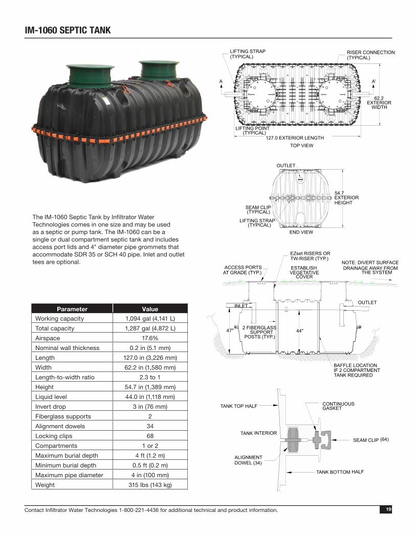
IM-1060 SEPTIC TANK
The IM-1060 Septic Tank by Infiltrator Water Technologies comes in one size and may be used as a septic or pump tank. The IM-1060 can be a single or dual compartment septic tank and includes access port lids and 4" diameter pipe grommets that accommodate SDR 35 or SCH 40 pipe. Inlet and outlet tees are optional.
Parameter ValueWorking capacity 1,094 gal (4,141 L)Total capacity 1,287 gal (4,872 L)Airspace 17.6%Nominal wall thickness 0.2 in (5.1 mm)Length 127.0 in (3,226 mm)Width 62.2 in (1,580 mm)Length-to-width ratio 2.3 to 1Height 54.7 in (1,389 mm)Liquid level 44.0 in (1,118 mm)Invert drop 3 in (76 mm)Fiberglass supports 2Alignment dowels 34Locking clips 68Compartments 1 or 2Maximum burial depth 4 ft (1.2 m)Minimum burial depth 0.5 ft (0.2 m)Maximum pipe diameter 4 in (100 mm)Weight 315 lbs (143 kg)
ACCESS PORTSAT GRADE (TYP.)
INLET
EZset RISERS ORTW-RISER (TYP.)
ESTABLISH VEGETATIVE
COVER
OUTLET
47" 44"
62.2EXTERIOR
WIDTH
TOP VIEW
LIFTING POINT(TYPICAL)
127.0 EXTERIOR LENGTH
RISER CONNECTION(TYPICAL)
LIFTING STRAP(TYPICAL)
A'A
END VIEW
LIFTING STRAP(TYPICAL)
SEAM CLIP(TYPICAL)
54.7EXTERIORHEIGHT
OUTLET
2 FIBERGLASSSUPPORT
POSTS (TYP.)
BAFFLE LOCATIONIF 2 COMPARTMENTTANK REQUIRED
NOTE: DIVERT SURFACEDRAINAGE AWAY FROM
THE SYSTEM
MID-HEIGHT SEAM SECTION DETAIL
TANK BOTTOM HALF
CONTINUOUSGASKET
SEAM CLIP (64)
TANK TOP HALF
ALIGNMENTDOWEL (34)
TANK INTERIOR
Contact Infiltrator Water Technologies 1-800-221-4436 for additional technical and product information.20
IM-1530 SEPTIC TANK
The IM-1060 Septic Tank by Infiltrator Water Technologies comes in one size and may be used as a septic or pump tank. The IM-1530 can be a single or dual compartment septic tank and includes access port lids and 4" diameter pipe grommets that accommodate SDR 35 or SCH 40 pipe. Inlet and outlet tees are optional.
Parameter ValueWorking capacity 1537 gal (5818 L)Total capacity 1787 gal (6765 L)Airspace 16.9%Length 176” (4460 mm)Width 62” (1567 mm)Length-to-width ratio 2.8 to 1Height 55” (1384 mm)Liquid level 44” (1118 mm)Invert drop 3 in (76 mm)Fiberglass supports 4Alignment dowels 46Locking clips 86Compartments 1 or 2Maximum burial depth 48” (1219 mm)Minimum burial depth 6” (152 mm)Maximum pipe diameter 4” (100 mm)Weight 501 lbs (228 kg)
PERCODE
PERCODE
44.0[1,118]LIQUIDDEPTH
3.0[76]
10.1 [257] FREEBOARD
175.6 [4,460] EXTERIOR LENGTH
61.7[1,567]
EXTERIORWIDTH
54.5[1,384]
EXTERIORHEIGHT
ISOMETRICVIEW
SIDE INLET/OUTLET (TYP.)
Ø 4 [102]PVC OR ABSINLET TEE
Ø 24.0 [610] ACCESS PORTWITH LOCKING LID (3)
INLETOUTLET
Ø 4 [102]PVC OR ABSOUTLET TEE
TANKINTERIOR
INLETTEE
LIDCONTINUOUSELASTOMERIC
GASKET
1.5 [38]
ALIGNMENTDOWEL
TANKINTERIOR
CONTINUOUS
ELASTOMERIC
GASKET
SEAM CLIP
TANK BOTTOM HALF
TANK TOP HALF
SECTION B - B'END VIEW
FIBERGLASSSUPPORT
2 [51] X 2 [51]FIBERGLASSSUPPORT (4)(TYP.)
16.9% AIR SPACE
SEAM CLIP(TYP.)
LIFTING STRAP(TYP.)
RISER CONNECTION (TYP.)LIFTING STRAP (TYP.)
LIFTING LUG (TYP.)
ACCESS PORT RIM
0.2 [5] WALLTHICKNESS
OUTLET TEE(TYP.)
PERCODE
PERCODE
44.0[1,118]LIQUIDDEPTH
3.0[76]
10.1 [257] FREEBOARD
175.6 [4,460] EXTERIOR LENGTH
61.7[1,567]
EXTERIORWIDTH
54.5[1,384]
EXTERIORHEIGHT
ISOMETRICVIEW
SIDE INLET/OUTLET (TYP.)
Ø 4 [102]PVC OR ABSINLET TEE
Ø 24.0 [610] ACCESS PORTWITH LOCKING LID (3)
INLETOUTLET
Ø 4 [102]PVC OR ABSOUTLET TEE
TANKINTERIOR
INLETTEE
LIDCONTINUOUSELASTOMERIC
GASKET
1.5 [38]
ALIGNMENTDOWEL
TANKINTERIOR
CONTINUOUS
ELASTOMERIC
GASKET
SEAM CLIP
TANK BOTTOM HALF
TANK TOP HALF
SECTION B - B'END VIEW
FIBERGLASSSUPPORT
2 [51] X 2 [51]FIBERGLASSSUPPORT (4)(TYP.)
16.9% AIR SPACE
SEAM CLIP(TYP.)
LIFTING STRAP(TYP.)
RISER CONNECTION (TYP.)LIFTING STRAP (TYP.)
LIFTING LUG (TYP.)
ACCESS PORT RIM
0.2 [5] WALLTHICKNESS
OUTLET TEE(TYP.)
Contact Infiltrator Water Technologies 1-800-221-4436 for additional technical and product information. 21
IM-1060 Inlet and Outlet Hole LocationsDrill height markings are provided on the Infiltrator IM-1060 to serve as a guide for inlet and outlet hole locations. The IM-1060 is manufactured to have an end inlet invert height of 47 inches (1,194 mm) above the interior surface of the tank bottom when using the drill height guide markings and 4-inch-diameter (100 mm) pipes. The end outlet invert height is 44 inches (1,118 mm), corresponding to a 3-inch (76 mm) drop from end inlet to end outlet. The side inlets have invert heights of 47.5 inches (1,207 mm), and side outlets have invert heights of 44.5 inches (1,130 mm). This corresponds to a side inlet to side outlet invert drop of 3 inches (76 mm); a side inlet to end outlet invert drop of 3.5 inches (89 mm); and an end inlet to side outlet invert drop of 2.5 inches (64 mm).
Height¹ Total Liquid Volume in Tank at Indicated Height
Please download the current Installation Instructions for the
IM-540, IM-1060 and IM-1530 Series Tanks atwww.infiltratorwater.com
IM-SERIES TANK NOMINAL VOLUME CHART
1. Height measured from lowermost inside surface at bottom of corrugation in tank.
Contact Infiltrator Water Technologies 1-800-221-4436 for additional technical and product information.22
RisersEZset by Infiltrator risers and lids are made from glass reinforced polypropylene, providing superior strength and durability. They come in green or black and in 20”, 24”, and 30” diameters making them ideal for use with any concrete or plastic tank. The slip resistant lids are fastened using stainless steel screws and can be further secured by installing locking rings.
20” Riser System• 20” x 6” Risers (Green or Black)• 20” x 12” Risers (Green or Black)• 20” Lids (Green or Black)
24” Riser System• 24” x 6” Risers (Green or Black)• 24” x 12” Risers (Green or Black)• 24” x 18” Risers (Green or Black)• 24” Lids (Green or Black)
30” Riser System• 30” x 12” Risers (Green or Black)• 30” Lids (Green or Black)
EZSET RISERS
Contact Infiltrator Water Technologies 1-800-221-4436 for additional technical and product information. 23
20 INCH RISER SIDE VIEWS(not to scale)
20”
22”
6.05”
.125 TYP. WALL THICKNESS
.121
.300
22.375”
SECTION A-ASCALE 1 : 6A
A
20”
22”
12.05”
.125 TYP. WALL THICKNESS
.121
.300
22.375”
SECTION A-ASCALE 1 : 6
A
24”
26”
18.05”
.125 TYP. WALL THICKNESS
.121
.300
26.375”
SECTION A-ASCALE 1 : 6
A
A
30”
32”
12.05”
.125 TYP. WALL THICKNESS
.121
.300
32.375”
SECTION A-ASCALE 1 : 6
A
A
24”
26”
12.05”
.125 TYP. WALL THICKNESS
.121
.300
26.375”
SECTION A-ASCALE 1 : 6A
24”
26”
6.05”
.125 TYP. WALL THICKNESS
.121
.300
26.375”
SECTION A-ASCALE 1 : 6A
A
24 INCH RISER SIDE VIEWS(not to scale)
30 INCH RISER SIDE VIEWS(not to scale)
EZSET RISERS
Contact Infiltrator Water Technologies 1-800-221-4436 for additional technical and product information.24
August 2015
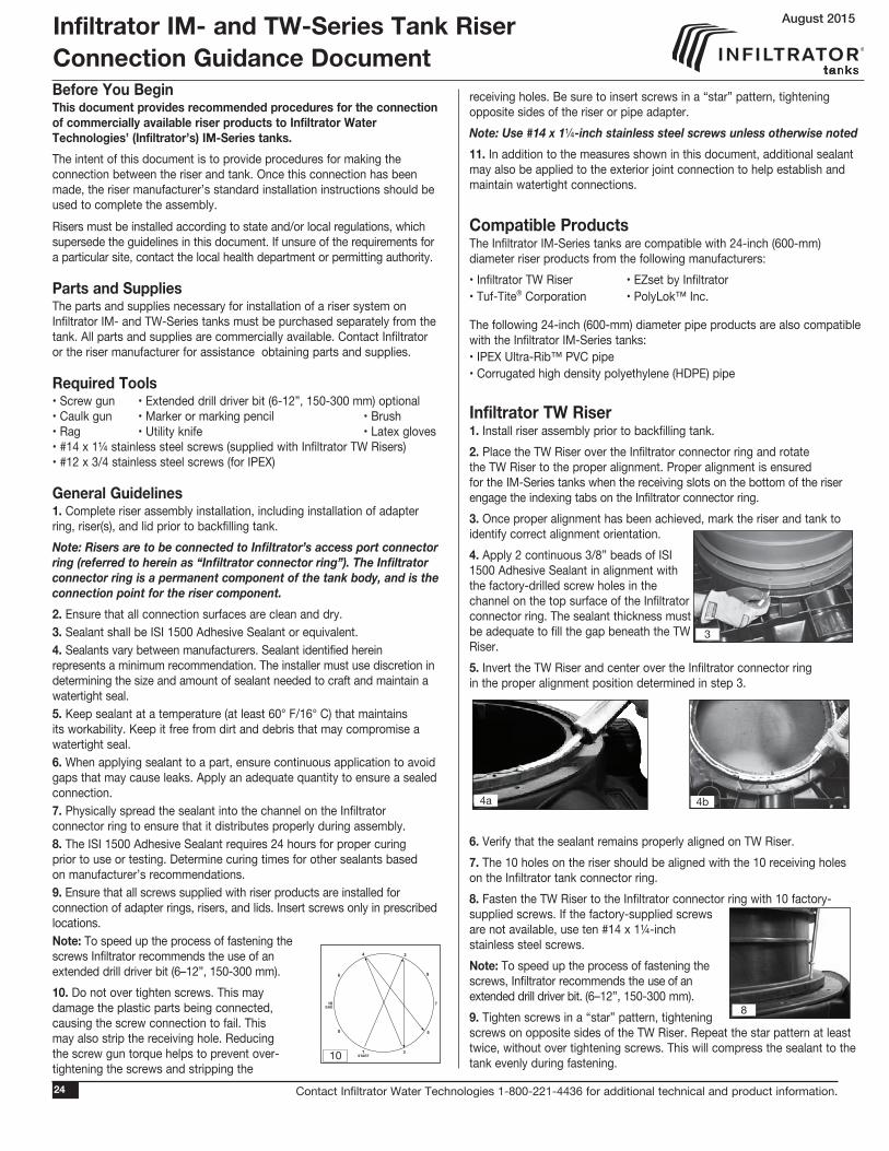
Before You BeginThis document provides recommended procedures for the connection of commercially available riser products to Infiltrator Water Technologies’ (Infiltrator’s) IM-Series tanks.The intent of this document is to provide procedures for making the connection between the riser and tank. Once this connection has been made, the riser manufacturer’s standard installation instructions should be used to complete the assembly.Risers must be installed according to state and/or local regulations, which supersede the guidelines in this document. If unsure of the requirements for a particular site, contact the local health department or permitting authority.
Parts and SuppliesThe parts and supplies necessary for installation of a riser system on Infiltrator IM- and TW-Series tanks must be purchased separately from the tank. All parts and supplies are commercially available. Contact Infiltrator or the riser manufacturer for assistance obtaining parts and supplies.
General Guidelines1. Complete riser assembly installation, including installation of adapter ring, riser(s), and lid prior to backfilling tank.Note: Risers are to be connected to Infiltrator’s access port connector ring (referred to herein as “Infiltrator connector ring”). The Infiltrator connector ring is a permanent component of the tank body, and is the connection point for the riser component.2. Ensure that all connection surfaces are clean and dry.3. Sealant shall be ISI 1500 Adhesive Sealant or equivalent.4. Sealants vary between manufacturers. Sealant identified herein represents a minimum recommendation. The installer must use discretion in determining the size and amount of sealant needed to craft and maintain a watertight seal.5. Keep sealant at a temperature (at least 60° F/16° C) that maintains its workability. Keep it free from dirt and debris that may compromise a watertight seal.6. When applying sealant to a part, ensure continuous application to avoid gaps that may cause leaks. Apply an adequate quantity to ensure a sealed connection.7. Physically spread the sealant into the channel on the Infiltrator connector ring to ensure that it distributes properly during assembly.8. The ISI 1500 Adhesive Sealant requires 24 hours for proper curing prior to use or testing. Determine curing times for other sealants based on manufacturer’s recommendations.9. Ensure that all screws supplied with riser products are installed for connection of adapter rings, risers, and lids. Insert screws only in prescribed locations.Note: To speed up the process of fastening the screws Infiltrator recommends the use of an extended drill driver bit (6–12”, 150-300 mm).10. Do not over tighten screws. This may damage the plastic parts being connected, causing the screw connection to fail. This may also strip the receiving hole. Reducing the screw gun torque helps to prevent over-tightening the screws and stripping the
receiving holes. Be sure to insert screws in a “star” pattern, tightening opposite sides of the riser or pipe adapter.Note: Use #14 x 1¼-inch stainless steel screws unless otherwise noted11. In addition to the measures shown in this document, additional sealant may also be applied to the exterior joint connection to help establish and maintain watertight connections.
Compatible ProductsThe Infiltrator IM-Series tanks are compatible with 24-inch (600-mm) diameter riser products from the following manufacturers:• Infiltrator TW Riser • EZset by Infiltrator • Tuf-Tite® Corporation • PolyLok™ Inc.
The following 24-inch (600-mm) diameter pipe products are also compatible with the Infiltrator IM-Series tanks:• IPEX Ultra-Rib™ PVC pipe• Corrugated high density polyethylene (HDPE) pipe
Infiltrator TW Riser1. Install riser assembly prior to backfilling tank.2. Place the TW Riser over the Infiltrator connector ring and rotate the TW Riser to the proper alignment. Proper alignment is ensured for the IM-Series tanks when the receiving slots on the bottom of the riser engage the indexing tabs on the Infiltrator connector ring. 3. Once proper alignment has been achieved, mark the riser and tank to identify correct alignment orientation.4. Apply 2 continuous 3/8” beads of ISI 1500 Adhesive Sealant in alignment with the factory-drilled screw holes in the channel on the top surface of the Infiltrator connector ring. The sealant thickness must be adequate to fill the gap beneath the TW Riser.5. Invert the TW Riser and center over the Infiltrator connector ring in the proper alignment position determined in step 3.
6. Verify that the sealant remains properly aligned on TW Riser.7. The 10 holes on the riser should be aligned with the 10 receiving holes on the Infiltrator tank connector ring.8. Fasten the TW Riser to the Infiltrator connector ring with 10 factory-supplied screws. If the factory-supplied screws are not available, use ten #14 x 1¼-inch stainless steel screws.Note: To speed up the process of fastening the screws, Infiltrator recommends the use of an extended drill driver bit. (6–12”, 150-300 mm).9. Tighten screws in a “star” pattern, tightening screws on opposite sides of the TW Riser. Repeat the star pattern at least twice, without over tightening screws. This will compress the sealant to the tank evenly during fastening.
Infiltrator IM- and TW-Series Tank Riser Connection Guidance Document
4a 4b
8
3
8
1
6
4
5
9
2
10 7
START
END
10
3
Contact Infiltrator Water Technologies 1-800-221-4436 for additional technical and product information. 25
10. Spread excess sealant in the interior joint between the tank and riser with a small putty knife or manually.11. Connect additional TW Riser sections or the included Infiltrator lid as needed.12. Backfill tank in accordance with Infiltrator’s tank installation instructions.13. Following tank backfilling, visually examine the riser to Infiltrator connector ring joint for damage resulting from backfill placement. Repair or replace if damaged. Allow a minimum sealant cure time of 24 hours before testing or placing into service.
EZset by Infiltrator Riser1. Install riser assembly prior to backfilling tank.2. Align EZset Riser Section over Infiltrator connector ring and mark 10 evenly spaced pilot hole locations so that they match up to receiving holes on the Infiltrator connector ring.3. Drill 10 new pilot holes into EZset Riser Section.4. Apply 2 continuous 3/8” beads of ISI 1500 Adhesive Sealant in alignment with the factory-drilled screw holes on the top surface of the Infiltrator connector ring. The sealant thickness must be adequate to fill the gap beneath the EZset Riser Section.5. Invert EZset Riser Section and center over the Infiltrator connector ring.6. Verify that the ISI 1500 Adhesive Sealant remains properly aligned on the EZset Riser Section.7. Align the 10 drilled pilot holes on the EZset Riser Section with the 10 receiving holes on the Infiltrator connector ring.Note: To speed up the process of fastening the screws, Infiltrator Water Technologies recommends the use of an extended drill driver bit (6–12”, 150-300 mm).8. Fasten the EZset Riser Section to the Infiltrator connector ring with ten #14 x 1¼-inch stainless steel screws.9. Tighten screws in a “star” pattern, tightening screws on opposite sides of the EZset Riser Section. Repeat the star pattern at least twice, without over tightening screws. Compress the ISI 1500 Adhesive Sealant to tank evenly during fastening.10. Spread the excess sealant into the interior joint between the tank and riser with a small putty knife or manually. Ensure there is even coverage on both surfaces.11. Connect additional EZset riser sections or EZset lid as needed.12. Note: Do not use the supplied Infiltrator tank lid, as it does not provide a watertight seal with the EZset riser. Instead, use EZset lid with the EZset riser.13. Backfill tank in accordance with Infiltrator’s tank installation instructions.14. Following tank backfilling, visually examine the riser to Infiltrator connector ring joint for damage resulting from backfill placement. Repair or replace if damaged. Allow a minimum sealant cure time of 24 hours before testing or placing into service.
Tuf-Tite® Corporation Riser1. Install riser assembly prior to backfilling tank.2. Align Tuf-Tite adapter ring over Infiltrator connector ring and mark 10 evenly spaced pilot hole locations so that they match up to receiving holes on the Infiltrator connector ring.3. Drill new pilot holes into Tuf-Tite adapter ring.4. Apply 2 continuous 3/8” beads of ISI 1500 Adhesive Sealant in alignment with the factory-drilled screw holes on the top surface of the Infiltrator connector ring. The sealant thickness must be adequate to fill the gap beneath the Tuf-Tite adapter ring. 5. Invert Tuf-Tite adapter ring and center over the Infiltrator connector ring. 6. Verify that the ISI 1500 Adhesive Sealant remains properly aligned on the Tuf-Tite adapter ring.7. Align the 10 drilled pilot holes on the Tuf-Tite adapter ring with the 10 receiving holes on the Infiltrator connector ring.8. Fasten the Tuf-Tite adapter ring to the Infiltrator connector ring with ten #14 x 1¼-inch stainless steel screws.9. Tighten screws in a “star” pattern, tightening screws on opposite sides of the Tuf-Tite adapter ring. Repeat the star pattern at least twice, without over tightening screws. Compress the ISI 1500 Adhesive Sealant to tank evenly during fastening.10. Connect the Tuf-Tite riser to the Tuf-Tite adapter ring and install lid according to Tuf-Tite’s instructions.Note: The Infiltrator tank lid provides a watertight seal with the Tuf-Tite riser and may be used.11. Backfill tank in accordance with Infiltrator’s tank installation instructions.12. Following tank backfilling, visually examine the riser to Infiltrator connector ring joint for damage resulting from backfill placement. Repair or replace if damaged. Allow a minimum sealant cure time of 24 hours before testing or placing into service.
PolyLok™ Inc. RiserNote: PolyLok riser must be installed using Infiltrator Pipe Adapter Ring. 1. Install riser assembly prior to backfilling tank.2. Align the 10 pilot holes on the PolyLok Riser-to-Riser Adapter Ring with the 10 receiving holes on the Infiltrator connector ring and mark both pieces to identify proper alignment.3. Apply 2 continuous 3/8” beads of ISI 1500 Adhesive Sealant in alignment with the factory-drilled screw holes on the top surface of PolyLok Riser-to-Riser Adapter Ring. Sealant thickness must fill gap beneath pipe adapter.4. Align the 10 blind pilot holes on the PolyLok Riser-to-Riser Adapter Ring with the 10 receiving holes on the Infiltrator connector ring using the marking made during step two. Center and press to create an even seal.
4
8
4
8
3
2
10
2
10
Contact Infiltrator Water Technologies 1-800-221-4436 for additional technical and product information.26
5. Fasten PolyLok Riser-to-Riser Adapter Ring to Infiltrator connector ring using ten #14 x 1¼-inch stainless steel screws.6. Tighten screws in a “star” pattern, tightening screws on opposite sides of the PolyLok Riser-to-Riser Adapter Ring. Repeat star pattern at least twice, without over tightening screws.7. Spread the excess sealant into the interior and exterior joint between the tank and riser with a small putty knife or manually. Ensure there is even coverage on both surfaces.8. Connect PolyLok riser to PolyLok Riser-to-Riser Adapter Ring and install according to PolyLok’s instructions.Note: Do not use the supplied Infiltrator tank lid, as it does not provide a watertight seal with the PolyLok Riser system.9. Backfill tank in accordance with Infiltrator’s tank installation instructions.10. Following tank backfilling, visually examine the riser to Infiltrator Tank Adapter Ring connection for damage resulting from backfill placement. Repair or replace if damaged. Allow 24 hours sealant cure time before testing or putting into service.
24-inch (600-mm) HDPE PipeNote: The 24-inch (600-mm) HDPE pipe must be installed using the Infiltrator Pipe Adapter Ring.1. Install riser assembly prior to backfilling tank.2. Cut HDPE pipe along an inner corrugation to allow lid to fit properly. Cut should be smooth and even.
3. Apply 2 continuous 3/8” beads of ISI 1500 Adhesive Sealant in alignment with the factory-drilled screw holes on the top surface of Infiltrator connector ring. Sealant thickness must fill gap beneath Infiltrator Pipe Adapter Ring.4. Align the 10 blind pilot holes on the Infiltrator Pipe Adapter Ring with the 10 receiving holes on the Infiltrator connector ring using the indexing tabs on the inside of the ring. Center and press to create an even seal.5. Fasten Infiltrator Pipe Adapter Ring to Infiltrator reinforcing ring using ten #14 x 1¼-inch stainless steel screws. Tighten in star pattern. Repeat star pattern at least twice, without over tightening screws.6. Spread excess sealant in the interior joint between the tank and riser with a small putty knife or manually.7. Center the HDPE pipe over the Infiltrator Pipe Adapter Ring. Note: Use additional ISI 1500 Adhesive Sealant to fill gap and seal space between the HDPE pipe and Infiltrator Pipe Adapter Ring.
8. Fasten HDPE pipe to Infiltrator Pipe Adapter Ring using four #12 x 1¼-inch (5.5 mm x 31 mm) stainless steel screws from inside the pipe.9. Tighten screws in a “star” pattern, tightening screws on opposite sides of the Infiltrator Pipe Adapter Ring. Repeat the star pattern at least twice, without over tightening screws. 10. Apply ISI 1500 Adhesive Sealant in the space between the pipe and Infiltrator Pipe Adapter Ring to continuously fill the gap. 11. Use the Infiltrator IM-Series septic tank lid, or equivalent product as a lid for the HDPE pipe. Follow lid manufacturer’s instructions to complete riser installation.12. Backfill tank in accordance with Infiltrator’s tank installation instructions.13. Following tank backfilling, visually examine the riser to Infiltrator Pipe Adapter Ring connection for damage resulting from backfill placement. Repair or replace if damaged. Allow 24 hours sealant cure-time before testing or putting into service. 24-inch (600-mm) IPEX Ultra-Rib™ PVC Pipe Note: 24-inch (600-mm) IPEX pipe must be installed using the
Infiltrator Pipe Adapter Ring.1. Install riser assembly prior to backfilling tank.2. Cut IPEX pipe along an inner corrugation to allow lid to fit properly. Cut should be smooth and even.3. Apply 2 continuous 3/8” beads of ISI 1500 Adhesive Sealant in alignment with the factory-drilled screw holes in the channel on the top surface of Infiltrator connector ring. Sealant thickness must fill gap beneath Infiltrator Pipe Adapter Ring.4. Align the 10 blind pilot holes on the Infiltrator Pipe Adapter Ring with the 10 receiving holes on the Infiltrator connector ring using the indexing tabs on the inside of the ring. Center and press to create an even seal.5. Fasten Infiltrator Pipe Adapter Ring to Infiltrator connector ring using ten #14 x 1¼-inch stainless steel screws. Tighten in star pattern. Repeat the star pattern at least twice, without over tightening screws.6. Mark (4) evenly spread locations on the Infiltrator Pipe Adapter Ring for pilot holes to accept screws. The pilot holes should be at a height half way up the interior flange of the Infiltrator Pipe Adapter Ring. 7. Drill (4) 1/8-inch (3.5-mm) pilot holes at marked locations on the Infiltrator Pipe Adapter Ring. 8. Apply (2) beads of ISI 1500 Adhesive Sealant to the Infiltrator Pipe Adapter Ring at the base of the flange.
5
3a 3b
7
8
3a 3b
8
7
5
Contact Infiltrator Water Technologies 1-800-221-4436 for additional technical and product information. 27
Disclaimer: These recommended procedures have been developed to identify best practices for achieving a watertight connection between the tank and riser under typical tank installation conditions. These procedures have been shown to result in a watertight connection between the riser assemblies identified in this document and the Infiltrator IM-Tank. Infiltrator does not guarantee a watertight connection between tank and riser because achieving a watertight connection is dependent upon a combination of installer practices and procedures, and field conditions. Please contact Infiltrator’s Technical Services Department at 800-221-4436 if difficulty is encountered during riser connection installation. Please contact the appropriate riser manufacturer for concerns associated with anything that does not involve the tank to-riser connection.
9. Place the IPEX pipe over the Infiltrator Pipe Adapter Ring until it is sealed at the base of the flange.10. Insert ISI 1500 Adhesive Sealan into the (4) pre-drilled pilot holes.11. Fasten IPEX pipe to Infiltrator Pipe Adapter Ring using (4) #12 x 1/2-inch stainless steel screws from the inside of pipe.12. Tighten screws in a “star” pattern, tightening screws on opposite sides of the Infiltrator Pipe Adapter Ring. Repeat the star pattern at least twice, without over tightening screws.13. Apply ISI 1500 Adhesive Sealant in the space between the pipe and Infiltrator Pipe Adapter Ring to fill the gap.14. Apply a generous bead of sealant into the groove at the base of the pipe and then smear the sealant into the groove between the pipe and Infiltrator Pipe Adapter Ring.15. Use the Infiltrator tank lid, or equivalent product as a lid. Follow lid manufacturer’s instructions to complete riser installation.16. Backfill tank in accordance with Infiltrator’s tank installation instructions.17. Following tank backfilling, visually examine the riser to Infiltrator Pipe Adapter Ring connection for damage resulting from backfill placement. Repair or replace if damaged. Allow 24 hours sealant cure-time before testing or putting into service.
9
Apply ISI 1500 Adheasive Sealant after installing pipe
Apply ISI 1500 Adheasive Sealant to pilot holes before installing screws
Apply ISI 1500 Adheasive Sealant after installing pipe.
Apply ISI 1500 Adheasive Sealant before installing pipe
10-14
Contact Infiltrator Water Technologies 1-800-221-4436 for additional technical and product information.28
Aquaworx Remediator: RKT-03 (Residential Unit)
Air Supply Line
Bacterial Growth Media (cuspated plastic)
Bacterial Catalyst Chamber
Septic Tank Effluent Inlet Holes
Fine Bubble Air Diffuser
Solid Bottom
The Aquaworx Remediator rejuvenates most failing septic systems. Insert it into an existing residential septic tank and it can reverse the biological clogging process causing the failure. The Remediator is an airlift column where bacteria are introduced to oxygen enriched effluent. The cuspated plastic around the bottom provides a substantial surface area for the colonization of bacteria.
SPECIFICATIONSDimensions: 36” h x 14” dia, 60 lbs with pumpHP 40 Pump: 120v/60hz/0.8 amps/96 wattsAir Delivery Rate: 1.5 CFM @ 4.6 feet. 40 L/min or 11 gal/minLiquid Mixing Rate: 16,000 GPDDigestion Rate: 1.5-2.5 lbs/BOD/dayMinimum Tank Depth: 3.5 feetMaximum Tank Depth: 6.9 feetMaximum Tank Size: 1500 gal/single unitDaily Treatment Volume: max. 600 gpd/single unit**Multiple units may be combined for high flows
COMPONENTS
1. Linear air pump with alarm2. Bacteria catalyst chamber3. Cuspate plastic media4. Fine bubble diffuser5. 1/2” PVC air line6. 12” PVC housing7. Bacteria catalyst
AQUAWORX
Contact Infiltrator Water Technologies 1-800-221-4436 for additional technical and product information. 29
AQUAWORX
Air Supply Line
Bacterial Growth Media (cuspated plastic)
Bacterial Catalyst Chamber
Septic Tank Effluent Inlet Holes
Fine Bubble Air Diffuser
Solid Bottom
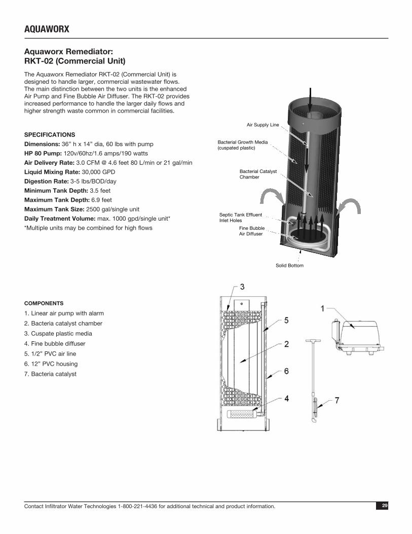
Aquaworx Remediator: RKT-02 (Commercial Unit)The Aquaworx Remediator RKT-02 (Commercial Unit) is designed to handle larger, commercial wastewater flows. The main distinction between the two units is the enhanced Air Pump and Fine Bubble Air Diffuser. The RKT-02 provides increased performance to handle the larger daily flows and higher strength waste common in commercial facilities.
SPECIFICATIONSDimensions: 36” h x 14” dia, 60 lbs with pumpHP 80 Pump: 120v/60hz/1.6 amps/190 wattsAir Delivery Rate: 3.0 CFM @ 4.6 feet 80 L/min or 21 gal/minLiquid Mixing Rate: 30,000 GPDDigestion Rate: 3-5 lbs/BOD/dayMinimum Tank Depth: 3.5 feetMaximum Tank Depth: 6.9 feetMaximum Tank Size: 2500 gal/single unitDaily Treatment Volume: max. 1000 gpd/single unit**Multiple units may be combined for high flows
COMPONENTS
1. Linear air pump with alarm2. Bacteria catalyst chamber3. Cuspate plastic media4. Fine bubble diffuser5. 1/2” PVC air line6. 12” PVC housing7. Bacteria catalyst
Contact Infiltrator Water Technologies 1-800-221-4436 for additional technical and product information.30
AQUAWORX INSTALLATION INSTRUCTIONS
Establish Location for Air PumpThe air pump can be located in a garage, shed, basement or other suitable structure. Locate the pump within 3 feet of an electrical source. If the locations described above are unavailable or impractical, the pump can be located in a plastic basin. The basin should be waterproof manufactured specifically for an outdoor environment. Locate the basin within 3 feet of the electrical source, preferably in a shady spot. (Complete basin installation instructions are provided in the Appendix.)
Install Airline from Air Pump to Riser1. Dig a 4-6 inch-wide by 8 to 12 inch-deep trench depending on minimum depth preferred in your area) from the air pump to septic tank riser so that trench intersects outside of riser at approximately a 90-degree angle. 2. Drill a 7/8-inch hole through the riser at or near the bottom of the trench. Install a 1/2-inch PVC SCH 40 pipe (not provided) through the hole so that it extends into the riser by at least 12 inches. This PVC pipe is the airline that will connect the air pump to the Aquaworx Remediator Unit. The area where the airline enters the riser must be sealed with mastic or by similar means.3. Run the 1/2-inch SCH 40 PVC pipe back to the air pump and glue the pipe into the air connections male adaptor (Figure 1).NOTE: Do not allow dirt or other contaminants to enter the airline. Additional fittings and pipe may be required depending on the location of the pump.
Install the Unit in the Septic Tank1. Be sure that the threaded rod has been removed from the top of the Unit. Do not remove the internal pipe and surrounding media from the center of the Aquaworx Remediator (Figure 2).2. Included with the Unit is a piece of rope made of a non-reactive material. Thread the ends of the rope through the holes left by the threaded rod and tie with non-slip knots. Pull hard against the knots to make certain they do not slip. The rope will be utilized to set the Unit into the septic tank and to remove it for future maintenance needs (Figure 3).
Before You BeginUnpack the Aquaworx Remediator Unit (Unit) and check for signs of damage. Notify Aquaworx™ immediately at 1-877-278-2979 if any damage has occurred. Remove the threaded rod from top of the Unit. The rod is a shipping aid and is not to be installed with the Unit. The following guidelines are for typical installations in a 850 to 2000 gallon residential septic tank. These installation instructions are general. Some installations may have differing additional requirements due to particular site conditions. Note: The Aquaworx Remediator site evaluation form must be completed prior to installation. The following guidelines pertain to both RKT-02 and RKT-03 units.
Septic Tank RequirementsA) RISERThe riser will provide access to the Unit for future inspections and maintenance. If there are no risers on the septic tank, then expose the top of septic tank so a riser (not provided) can be installed. Risers shall be approved by the local authority and be installed per manufacture’s installation instructions. The lid shall be secure to prevent unauthorized access and have provisions for safe access. Install the riser over the septic tank opening where the Unit will be installed.
B) UNIT LOCATIONIf the tank is a dual-compartment septic tank then install the Unit at the outlet end. However if there are access limitations/obstructions, then the Unit can be installed at the inlet end. For a single-compartment tank, the Unit may be placed in either end of the tank. For an onsite system having more than one tank installed in series, install the Unit in the first tank.
C) MINIMUM AND MAXIMUM SOLID DEPTHS• Floating solids layer shall be less than 6 inches• Bottom sludge layer shall be less than 3 inches• If the layers are greater then have the tank pumped
D) TANK PUMPING AND INSPECTION RECOMMENDATIONSPumping the tank is not a requirement, but if it is necessary then it is recommended that the tank be visually inspected for cracks or leaks from house plumbing, baffles, concrete corrosion, inlet and outlet tees. NOTE: Aquaworx recommends a minimum liquid depth of 38” for proper unit operation. After pumping (if necessary), either refill the septic tank with the recommended 38” liquid depth or allow for sufficient time for the tank to refill prior to turning the Unit on.
Rake and Shovel Screwdriver and Wrench Hand Saw and Tape Measure Primer and Glue Protective Gloves and Mastic Riser (if not on septic tank)
1/2” PVC Schedule 40 Pipe Multiple 1/2” PVC 90o Elbows 1/2” Quick Connect Union Anti-tampering screws 1/2” PVC Tee or Elbow S1/2” Hole Saw/Drill Bit
Materials and Equipment Needed
Figure 1
AIR PUMP
AIR LINE ASSEMBLY INSTALLED BELOW GRADE IN SHALLOW HAND DUG TRENCH
INSERT REMEDIATOR THROUGH RISEROPENING AND LOWER TO THE BOTTOMOF THE TANK GUIDED BY ROPES.
REMEDIATOR
REMOVETHREADED ROD
ROPE
HOLE FROMREMOVED
THREADED ROD
TIE SECUREKNOT
ROPE
1/2" PVC SCH40 PIPE
NOTE: LENGTH SHOULD BE ABLE TO REACH THE TOP OF THE RISER ASSEMBLY.
INSERT AND GLUE AIRLINE ASSEMBLY.
1/2" PVC AIR LINE
BACTERIAL CATALYST ASSEMBLY
AQUAWORXREMEDIATOR
Contact Infiltrator Water Technologies 1-800-221-4436 for additional technical and product information. 31
AQUAWORX INSTALLATION INSTRUCTIONS
3. Prime and glue a piece of 1/2-inch SCH 40 PVC pipe (not provided) into the coupling within the 4-inch center tube (Figures 4 & 5). Note: Use care to ensure a tight connection. The vertical PVC pipe is also part of the inlet airline assembly. The length of this pipe should allow it to vent.4. Using the rope provided lower Unit into the tank (Figures 6 & 7). NOTE: Place the Unit with the airline assembly as close as possible to the inside wall of the riser. Because the Unit sits on the bottom of the septic tank, the rigid PVC airline assembly adds stability when glued in place. The Unit should be positioned below the riser for easy access to the top of the Unit.5. Anchor the rope to the ground with a stake or large rock so that it does not fall into the tank while completing the airline assembly. 6. To complete the airline assembly, cut the two PVC pipes to the appropriate length. Make a glued connection with a 1/2-inch PVC 90 (not provided) (Figure 8). NOTE: If installing a quick connect union (recommended), cut the horizontal pipe to a shorter length allowing for the extra connection. 7. Remove the Bacterial Catalyst Assembly from the packaging. Note: Wash hands after handling. Glue a 1/2-inch PVC SCH 40 pipe (not provided) into the coupling end of the Bacterial Catalyst Assembly creating an extension. The extension should be long enough to extend up into the riser when the Bacterial Catalyst Assembly is set down into the installed Unit. 8. Cut the PVC pipe to a length so that it is a few inches below the lid of the riser and glue on a 1/2-inch PVC tee or elbow (not provided) as a handle. This facilitates the removal and replacement of the Bacterial Catalyst Assembly.9. Slide the PVC extension with the Bacterial Catalyst Assembly down the center PVC pipe of the Unit (Figure 9).NOTE: Do not force the Bacterial Catalyst Assembly into the Unit. As long as it is submerged within the air column in the Unit then it is positioned correctly.10. Secure the Bacterial Catalyst Assembly by clipping the “C” clip (provided) around the PVC pipe coming out of the Unit (Figure 10). 11. Tie off the excess rope from the Unit to the horizontal airline pipe (Figure 11).
AIR PUMP
AIR LINE ASSEMBLY INSTALLED BELOW GRADE IN SHALLOW HAND DUG TRENCH
INSERT REMEDIATOR THROUGH RISEROPENING AND LOWER TO THE BOTTOMOF THE TANK GUIDED BY ROPES.
REMEDIATOR
REMOVETHREADED ROD
ROPE
HOLE FROMREMOVED
THREADED ROD
TIE SECUREKNOT
ROPE
1/2" PVC SCH40 PIPE
NOTE: LENGTH SHOULD BE ABLE TO REACH THE TOP OF THE RISER ASSEMBLY.
INSERT AND GLUE AIRLINE ASSEMBLY.
1/2" PVC AIR LINE
BACTERIAL CATALYST ASSEMBLY
AQUAWORXREMEDIATOR
Figure 4 Figure 5
Figure 6 Figure 7
Figure 8
Figure 9
Figure 10 Figure 11
Contact Infiltrator Water Technologies 1-800-221-4436 for additional technical and product information.32
AQUAWORX INSTALLATION INSTRUCTIONS
Start up the Unit1. Plug the air pump into a GFCI rated electrical outlet. Make sure the air pump begins to operate. (Listen for a humming sound.)2. Check all PVC pipe and fitting joints for evidence of air leaks. Make sure liquid over the Unit is being actively agitated and aerated and the Bacterial Catalyst Assembly is submerged (Fig. 12). 3. Unpleasant and noxious odors will become noticeable, but should subside within 48 hours. Avoid breathing the gases from the septic tank. Place the riser lid over the top of the riser opening to reduce exposure to these gases. White PVC pipe and fittings are not UV resistant. All exposed pipe and fittings must be covered or painted (not provided).4. Install septic tank riser lid with anti-tampering screws (not provided). Make certain all lids are child proof. 5. Backfill trenches and bury all 1/2-inch PVC pipes to restore the landscaping. Follow-up inspections are recommended at one week and three weeks after start up.
WarningAll electrical installations to be completed according to local codes and ordinances. all electrical work to be done by qualified electrician. Never enter an empty septic tank. Septic gases are extremely hazardous and can cause death. Detectable and non-detectable poisonous gases will remain in the empty septic tank. Do not breathe septic gases while working around open septic tanks. Exposure to methane and hydrogen sulfide can be harmful.As the Unit begins to operate within the septic tank, unpleasant and offensive odors will increase and become very noticeable. These odors normally disappear after a day or two. After start up of the Unit, a foam or bubbly flock may occur within a week or two. If foam is present then wash down with a hose.
Air Pump RequirementsThe Air Pump can be located in a garage, shed, basement or other suitable structure. When these are unavailable or impractical it can be located in a plastic basin. There are many plastic basins available. The basin should have a minimum diameter of 20 inches and minimum height of 12 inches.It should be constructed of material designed to withstand exterior installation and provide a waterproof environment for the
air pump. Locate the basin within 3 feet of the electrical source in a shady spot. Burying the basin is not recommended, since there is potential for moisture, condensation or water to collect in the basin. In addition, it may allow excessive heat build up. These conditions can cause the air pump to malfunction.
Connect Basin Air Line to Air PumpThe Aquaworx Remediator package includes a clear tube air pump connector with two hose clamps, and a barbed glued fitting connected to a PVC 90-degree elbow. Please locate and set aside. 1. Cut the PVC close nipple (provided) to 1 1/2-inches in and glue the close nipple into the female adaptor. Make certain the threaded barb adaptor on the clear tube air pump connector is tightly threaded into the PVC 90-degree elbow (provided). Tighten the hose clamp on the barb end (provided). Position the air pump in the center of the basin. DO NOT GLUE THIS CONNECTION NOW! Estimate the correct length for the clear plastic tubing and cut (Figure 13). 2. Remove the air pump and the clear tube connector. Put the second hose clamp (provided) over the open end of the clear plastic tube, slide the tube over the outlet port of the air pump and tighten the hose clamp (Figures 14 & 15). 3. Reposition the air pump within the basin, now connected to the clear tube connector, slip the PVC 90-degree elbow over the close nipple to insure the clear tube is not kinked, then glue the PVC 90-degree elbow on the close nipple (Figure 16).
Figure 12
Figure 13
Figure 14
Figure 15
Figure 16
Contact Infiltrator Water Technologies 1-800-221-4436 for additional technical and product information. 33
AQUAWORX INSTALLATION INSTRUCTIONS
Make Electrical Connection to Basin and Air PumpNOTE: Hire a qualified electrician to wire a GFCI protected connection to the air pump.
SUGGESTED ELECTRICAL CONDUIT ASSEMBLYRequired components:• 1/2-inch Carlon (or similar) Gray Electrical Male Adapter• 1/2-inch Carlon (or similar) PVC Entry Elle• 1/2-inch PVC SCH 40 Pipe• 3/4-inch Barb End Spade Bit• EMT Lock Nut• Wet or Dry PVC Glue1. Install a 1/2-inch Carlon (or similar) gray electrical male adaptor (not provided) by drilling another 3/4 inch hole, typically at 90 or 180 degrees from the airline connection male adaptor. Follow the same procedure as the air line male adaptor installation except use an EMT lock nut on the inside of the basin instead of the female adaptor (Figure 17). 2. Cut a close nipple approximately 1 1/2 inches long from 1/2-inch PVC pipe (not provided) and glue it into the Carlon male adaptor. Glue a 1/2-inch Carlon PVC entry “L” (not provided) onto the close nipple in the position best suited to connect to the electrical service. Leaving it unglued for the electrician is also an option. Check to make certain the electrician properly glued this connection (Figure 18). NOTE: The electrician can connect the electrical service to this entry or make his own waterproof connection to the basin. The electrician must connect the basin and air pump to a GFCI protected service that meets the codes and ordinances of the local authority having jurisdiction over electrical installations.
Figure 17
Figure 18
Contact Infiltrator Water Technologies 1-800-221-4436 for additional technical and product information.34
Site Evaluation ChecklistDate of Evaluation People Present
Property Owner Rent or Own
Property Address City State ZIP __________
Home Phone Cell Phone Work Phone
Other Information
FLOW ESTIMATES
# of Bedrooms # of Bedrooms on Permit # of Occupants Garbage disposal
Laundry machine volume in gal. # of Laundry loads per week Water Softener
Water Softener plumbed to Septic Tank? # of cycles per day Volume of cycles
Plumbing fixtures checked for leaks?
SYSTEM INFORMATIONAge of System Permit Obtained # of system replacements on property
Tank Volume Tank Depth # of Tank compartments Tank checked for leaks
Type of System: Trench Bed Mound At Grade Drip
Media Type
Dimensions of the Field Trench Length Trench Width
Depth of the Field Depth of Cover Nature of Cover: Loose
Compacted Fill Material Present Type of fill material
Effluent Filter present Type / MFG Subsurface Drainage
Is subsurface drainage functioning
How often has Tank been serviced Were records kept
SOIL INFORMATIONSoil type in location of field Soil loading rate of field area
Depth to seasonal or perched water table Separation of water table to field bottom
Depth to other limiting condition Separation of other limiting condition to field bottom
Was soil report completed Name of soil evaluator
Other Comments:
Attach copies of all septic permits obtained for this site, tank pumping records and soil reports.
AQUAWORX
Contact Infiltrator Water Technologies 1-800-221-4436 for additional technical and product information. 35
AQUAWORX
Certified Installer AgreementCounty __________________________________________________________ Counties within Service Area _________________________________________
Email ____________________________________________________________ Certified Installer/Contractor License Number _________________________
This Certified Installer Agreement (the “Agreement”) dated ______________________ by and between Infiltrator Water Technologies. (“ISI”), a Connecticut corporation with its principal place of business at 4 Business Park Road, Old Saybrook, CT 06475 and “Installer” (information listed above).WHEREAS, ISI is the manufacturer of the Aquaworx Remediator™ and accompanying accessories including the Bacterial Catalyst, the Aquaworx Remediator™ Air Pump and the Air Basin Assembly (the “Products”);WHEREAS, ISI is the owner or licensee of certain trademarks as set forth on Exhibit A (the “Marks”) and the goodwill represented by the Marks;WHEREAS, the Installer desires to hold itself out to the public as a “Certified Installer” of the Products and ISI desires to appoint Installer as a Certified Installer of the Products under the terms set forth in this Agreement;NOW, THEREFORE, in consideration of the premises and the mutual covenants and promises of the parties, the sufficiency of which is acknowledged, the parties agree as follows:1. Prior to commencing its business as a Certified Installer hereunder, Installer shall take a certification course established by ISI. Upon successful completion of the certification course, Installer is issued a certificate card to be used as proof of completion with customers and regulators. Installer shall follow all of ISI’s installation instructions, including without limitation, providing to ISI a fully completed and executed Site Evaluation Form following each installation of a Product. Installer agrees that it shall be fully responsible for all warranty claims in the event that it does not comply with the installation instructions and site evaluation requirements.2. Installer shall be fully responsible for all permits and licenses with regard to any installation or maintenance of the Products. Installer shall be fully licensed to install and maintain the Products and shall provide ISI copies of such licenses upon request. All work performed as a Certified Installer hereunder shall be in full compliance will all applicable laws and regulations. Installer shall only use ISI approved methods and materials in the installation and maintenance of the Products. All electrical connections shall be made by licensed electrician as may be required by local regulation.3. ISI will provide the Installer technical support on the installation and maintenance of the Products and forward sales leads to Installer in its local area.4. Installer shall provide each of its customers with a copy of ISI’s Limited Warranty for the Product being sold.5. ISI shall assume no liability to Installer or any third party with respect to the services rendered by Installer. Installer hereby indemnifies and holds ISI harmless against any loss or losses as a result of claims, actions, lawsuits and investigations, including without limitation, attorneys fees involving or arising from Installer’s activities as a Certified Installer of the Products, including, without limitation, its sales and installation activities.6. a. Installer agrees to maintain in full force and effect insurance coverage in such amounts to satisfy the minimum liability, workman’s
compensation, and commercial automobile as required by the state or local licensing agreement. OR b. In the event that the state or local licensing agency does not have minimum insurance requirements, the Installer shall maintain in full
force and effect (a) Commercial General Liability insurance for damages claims due to bodily injury (including death) or property damage caused by or arising from acts or omissions of Installer, including broad form property damage and blanket contractual liability with limits of $1,000,000 per occurrence; (b) Workers Compensation insurance in compliance with all statutory requirements as well as employer’s liability insurance with limits of $500,000; (c) Commercial automobile insurance for all owned, non-owned or hired automobiles with limits of at least $1,000,000 per occurrence; and (d) Umbrella liability insurance with limits of $1,000,000. Installer shall upon execution hereof and thereafter upon request provide ISI a certificate of insurance evidencing all such required coverage and proof of a current contractor’s license.
7. Subject to the terms and conditions of this Agreement, ISI hereby appoints Installer as a “Certified Installer” of the Products and grants to Installer a non-exclusive, non-transferable, limited license to use the Marks in connection with its business as a Certified Installer of the Products. Whenever a Mark is used as provided herein, the Mark shall be accompanied by appropriate notice of statutory rights (“®”) or common law rights (“™”), as directed by ISI, or other such words and/or symbols as may be requested by ISI from time to time. Installer will use a Mark only in the style and according to the specifications reflected in Exhibit A. Installer agrees that all rights in and to the Marks are and shall remain vested in ISI, and that all rights accruing from Installer’s use of the Marks shall inure to Licensor.8. This Agreement may be terminated by ISI for breach of any of Installer’s obligations hereunder without notice. This Agreement may be terminated by either ISI or Installer at any time and without any reason upon thirty (30) days notice. Paragraph 5 shall survive any termination of this Agreement. Upon termination, Installer shall immediately stop using the Marks and no longer hold itself out to the public as a Certified Installer of the Products.9. This Agreement will be governed by and interpreted in accordance with the laws of the State of Connecticut without regard to conflicts of laws principles.10. This Agreement may be executed in counterparts and/or by facsimile.
Infiltrator Water Technologies. Installer ______________________________________________________
Contact Infiltrator Water Technologies 1-800-221-4436 for additional technical and product information.36
AQUAWORX
1-Year Suggested Service Agreement
This service agreement (the “Agreement”) is dated , 20 , between
“Service Provider” and “Owner” (Collectively, the “Parties”).
THE PARTIES AGREE AS FOLLOWS:
1) SERVICES:The Service Provider shall provide the minimum service outlined in the Maintenance Schedule below. The Service Provider shall provide all labor, transportation and equipment needed to properly inspect and service the Aquaworx Remediator™ system
2) REPLACEMENT OF COMPONENTS:The Service Provider will replace worn / non-functional parts and components at the Owner’s expense. Such items may include but not be limited to: air pump components, air pump, generator components, bacteria catalyst, riser, riser lid, basin, basin lid, grommets, electrical connections and rubber seals. The Service Provider shall provide the Owner with a list and cost of proposed replacement components prior to installation.
3) MAINTENANCE SCHEDULE:The Service provider shall make a minimum of one site inspection at each of the intervals listed below:
A) Start up* (1-3 weeks) – Inspections of all accessible system components for proper fit and function. Verification of solid levels and reduced odors in septic tank and visual inspection for surfacing effluent above leachfield.
B) Mid Year (6 months) – Inspections of all accessible system components for proper fit and function. Verification of solid levels and reduced odors in septic tank and visual inspection for surfacing effluent above leachfield. Cleaning of air pump filter and inspection of basin assembly, septic tank riser, riser lid and seals. Removal and replacement of Bacterial Catalyst assembly.
C) Year End (12 months) - Inspections of all accessible system components for proper fit and function. Verification of solid levels and reduced odors in septic tank and visual inspection for surfacing effluent above leachfield. Cleaning of air pump filter and inspection of basin assembly, septic tank riser, riser lid and seals. Removal and replacement of Bacterial Catalyst assembly.
4) PAYMENT:The Owner shall pay the Service Provider a service fee of $ within one week of the initial system installation. The Service Agreement may be renewed 30 days prior to end of each one-year term.
5) TERM:This service agreement shall be in effect for a period of one year. The Service Agreement may be renewed for total period of three years. Operation of the Aquaworx Remediator™ system without a service agreement shall void the manufacturer’s limited warranty.
OWNER SERVICE PROVIDER
Printed name Printed name
Date Date
* NOTE: Start-up inspection is not required for years 2 and 3, if the service agreement is extended.
Contact Infiltrator Water Technologies 1-800-221-4436 for additional technical and product information. 37
EZFLOW SYSTEMS
EZflow Systems in Arkansas
The Arkansas Product Review Committee and Department of Health have evaluated the EZflow 1201P-GEO and 1202H-GEO specifications and a product sample. This product has been approved for use as a substitute for conventional pipe and gravel in absorption trenches. The approval of the 1201P-GEO and 1202H-GEO indicates that the product meets the Rules and Regulations Pertaining to Sewage Disposal Systems, Designated Representatives and Installers, Act 402 of 1977, A.C.A. 12-236-101 et seq., and with all manufacturers specifications that do not conflict with the standards. Specifically, the site and soils must be classified as suitable or provisionally suitable for a conventional system or have an acceptable percolation rate and allow for the required vertical separation to limiting soil horizons.The most suitable backfill material available should be used. Clay backfill is not recommended. The backfill should be mounded over the trench to allow for settling and ensure a minimum of six inches of cover as specified by the manufacturer.
Materials and Equipment Needed EZflow 1201P-GEO or EZflow 1202H-GEO bundles EZflow internal pipe couplers Endcaps, if needed Backhoe Laser, Transit or Level
Products1201P-GEO 1202H-GEO
Installation Instructions1. The EZflow assemblies are 12 inches in diameter by 10 feet long. The polyethylene net bundles contain a four inch perforated pipe surrounded by EPS aggregate. In cases where linear footage required is not in multiples of 10, the installer may (a) reduce the product to the needed length and refasten the netting to the pipe or, (b) use an additional 10 feet of product to exceed the required trench length.NOTE: The required length of drainfield is that required for a two foot wide stone trench.2. The plastic stretch wrap is removed before the ten foot long bundles are placed in the trench(es).3. The top of each GEO cylinder contains a filter fabric pre-manufactured in between the netting and aggregate. The fabric is inserted to prevent soil intrusion. The installer shall make sure that the fabric is on top with the 1201P-GEO or 1202H-GEO configuration, that it is in contact with the fabric contained in the adjacent cylinder before backfilling.4. The bundles containing 4-inch perforated pipe are joined end to end with an internal coupling available from EZflow. The same internal coupler is used to start the trench, as it will slide inside the 4-inch PVC pipe.5. The trench top shall be shaped to ensure surface runoff. Minimum cover over the pipe and aggregate assembly shall be 6 inches. Mounding of backfill may be necessary to ensure the required 6 inches of cover.6. Repeat steps 1 through 5 for each required trench.
18"MAXIMUM
TRENCH WIDTH
24" MAXIMUMTRENCH WIDTH
Contact Infiltrator Water Technologies 1-800-221-4436 for additional technical and product information.38
EZ 1201P-GEO Trench ConfigurationsTYPICAL CROSS SECTION (not to scale)
TYPICAL PLAN VIEW (not to scale)
TYPICAL SIDE VIEW (not to scale)
EZFLOW SYSTEMS
12" MIN. TRENCH WIDTH
GEOTEXTILE
4" PERFORATED PIPE
ESTABLISH VEGETATIVE COVER
NATIVE BACKFILL
EZFLOW BUNDLE (TYP.)
1201P GEOEZFLOW BUNDLE (TYP.)
4" PVC PIPE
4" PVC 90°
DISTRIBUTION BOX
INFILTRATORSEPTIC TANK
1201P GEOEZFLOW BUNDLE
INFILTRATOR SEPTIC TANK
Contact Infiltrator Water Technologies 1-800-221-4436 for additional technical and product information. 39
EZFLOW SYSTEMS
EZ 1202H-GEO Trench Configurations
TYPICAL CROSS SECTION (not to scale)
TYPICAL PLAN VIEW (not to scale)
TYPICAL SIDE VIEW (not to scale)
TOTAL LENGTH OFSYSTEM PER PLAN
1202H GEOEZFLOW BUNDLE (TYP.)
4" PVC PIPE
4" PVC 90°
INFILTRATORSEPTIC TANK
DISTRIBUTIONBOX
24"
PROTECTIVE GEOTEXTILECOVERAGE: 180°
EZFLOW
BUNDLE (TYP.)
MINIMUM 6” NATIVEBACKFILL
12”
1202H GEOEZFLOW BUNDLE
INFILTRATOR SEPTIC TANK
Contact Infiltrator Water Technologies 1-800-221-4436 for additional technical and product information.40
INFILTRATOR WATER TECHNOLOGIES STANDARD LIMITED WARRANTY
(a) The structural integrity of each chamber, endcap and other accessory manufactured by Infiltrator (collectively referred to as “Units”), when installed and operated in a leachfield of an onsite septic system in accordance with Infiltrator’s installation instructions, is warranted to the original purchaser (“Holder”) against defective materials and workmanship for one year from the date upon which a septic permit is issued for the septic system containing the Units; provided, however, that if a septic permit is not required for the septic system by applicable law, the one (1) year warranty period will begin upon the date that installation of the septic system commences. In order to exercise its warranty rights, Holder must notify Infiltrator in writing at its corporate headquarters in Old Saybrook, Connecticut within fifteen (15) days of the alleged defect. Infiltrator will supply replacement Units for those Units determined by Infiltrator to be defective and covered by this Limited Warranty. Infiltrator’s liability specifically excludes the cost of removal and/or installation of the Units.
(b) THE LIMITED WARRANTY AND REMEDIES IN SUBPARAGRAPH (a) ARE EXCLUSIVE. THERE ARE NO OTHER WARRANTIES WITH RESPECT TO THE UNITS, INCLUDING NO IMPLIED WARRANTIES OF MERCHANTABILITY OR FITNESS FOR A PARTICULAR PURPOSE.
(c) This Limited Warranty shall be void if any part of the chamber system (chamber, endcap or other accessory) is manufactured by anyone other than Infiltrator. The Limited Warranty does not extend to incidental, consequential, special or indirect damages. Infiltrator shall not be liable for penalties or liquidated damages, including loss of production and profits, labor and materials, overhead costs, or other losses or expenses incurred by the Holder or any third party. Specifically excluded from
Limited Warranty coverage are damage to the Units due to ordinary wear and tear, alteration, accident, misuse, abuse or neglect of the Units; the Units being subjected to vehicle traffic or other conditions which are not permitted by the installation instructions; failure to maintain the minimum ground covers set forth in the installation instructions; the placement of improper materials into the system containing the Units; failure of the Units or the septic system due to improper siting or improper sizing, excessive water usage, improper grease disposal, or improper operation; or any other event not caused by Infiltrator. This Limited Warranty shall be void if the Holder fails to comply with all of the terms set forth in this Limited Warranty.
Further, in no event shall Infiltrator be responsible for any loss or damage to the Holder, the Units, or any third party resulting from installation or shipment, or from any product liability claims of Holder or any third party. For this Limited Warranty to apply, the Units must be installed in accordance with all site conditions required by state and local codes; all other applicable laws; and Infiltrator’s installation instructions.
(d) No representative of Infiltrator has the authority to change this Limited Warranty in any manner whatsoever, or to extend this Limited Warranty. No warranty applies to any party other than the original Holder.
The above represents the standard Limited Warranty offered by Infiltrator. A limited number of states and counties have different warranty requirements. Any purchaser of Units should contact Infiltrator’s corporate headquarters in Old Saybrook, Connecticut, prior to such purchase, to obtain a copy of the applicable warranty, and should carefully read that warranty prior to the purchase of Units.
WARRANTIES
Contact Infiltrator Water Technologies 1-800-221-4436 for additional technical and product information. 41
WARRANTIES
INFILTRATOR WATER TECHNOLOGIES STANDARD LIMITED WARRANTY
(a) This limited warranty is extended to the end user of an Infiltrator Tank. A Tank manufactured by Infiltrator, when installed and operated in accordance with Infiltrator’s installation instructions and local regulation by a licensed installer, is warranted to you: (i) against defective materials and workmanship for five (5) years after installation. Infiltrator will, at its option, (i) repair the defective product or (ii) replace the defective materials. Infiltrator’s liability specifically excludes the cost of removal and/or installation of the Tank.
(b) In order to exercise its warranty rights, you must notify Infiltrator in writing at its corporate headquarters in Old Saybrook, Connecticut within fifteen (15) days of the alleged defect.
(c) YOUR EXCLUSIVE REMEDY WITH RESPECT TO ANY AND ALL LOSSES OR DAMAGES RESULTING FROM ANY CAUSE WHATSOEVER SHALL BE SPECIFIED IN SUBPARAGRAPH (a) ABOVE. INFILTRATOR SHALL IN NO EVENT BE LIABLE FOR ANY CONSEQUENTIAL OR INCIDENTAL DAMAGES OF ANY KIND, HOWEVER OCCASIONED, WHETHER BY NEGLIGENCE OR OTHERWISE. SOME STATES DO NOT ALLOW THE EXCLUSION OR LIMITATION OF INCIDENTAL OR CONSEQUENTIAL DAMAGES, SO THIS LIMITATION OR EXCLUSION MAY NOT APPLY TO YOU. THIS WARRANTY GIVES YOU SPECIFIC LEGAL RIGHTS AND YOU MAY ALSO HAVE OTHER RIGHTS WHICH VARY FROM STATE TO STATE.
(d) THIS LIMITED WARRANTY IS THE EXCLUSIVE WARRANTY GIVEN BY INFILTRATOR AND SUPERSEDES ANY PRIOR, CONTRARY, ADDITIONAL, OR SUBSEQUENT REPRESENTATIONS, WHETHER ORAL OR WRITTEN. INFILTRATOR DISCLAIMS AND EXCLUDES TO THE GREATEST EXTENT ALLOWED BY LAW ALL OTHER WARRANTIES, WHETHER EXPRESS OR IMPLIED, OR STATUTORY, INCLUDING ANY WARRANTY OF MERCHANTABILITY,
FINESSE FOR A PARTICULAR PURPOSE AND ANY IMPLIED WARRANTIES OTHERWISE ARISING FROM COURSE OF DEALING, COURSE OF PERFORMANCE, OR USAGE OF TRADE. NO PERSON (INCLUDING ANY EMPLOYEE, AGENT, DEALER, OR REPRESENTATIVE) IS AUTHORIZED TO MAKE ANY REPRESENTATION OR WARRANTY CONCERNING THIS PRODUCT, EXCEPT TO REFER YOU TO THIS LIMITED WARRANTY. EXCEPT AS EXPRESSLY SET FORTH HEREIN, THIS WARRANTY IS NOT A WARRANTY OF FUTURE PERFORMANCE, BUT ONLY A WARRANTY TO REPAIR OR REPLACE.
(e) YOU MAY ASSIGN THIS LIMITED WARRANTY TO A SUBSEQUENT PURCHASER OF YOUR HOME.
(F) NO REPRESENTATIVE OF INFILTRATOR HAS THE AUTHORITY TO CHANGE THIS LIMITED WARRANTY IN ANY MANNER WHATSOEVER, OR TO EXTEND THIS LIMITED WARRANTY.
CONDITIONS AND EXCLUSIONSThere are certain conditions or applications over which Infiltrator has no control. Defects or problems as a result of such conditions or applications are not the responsibility of Infiltrator and are NOT covered under this warranty. They include failure to install the Tank in accordance with instructions or applicable regulatory requirements or guidance, altering the Tank contrary to the installation instructions and disposing of chemicals or other materials contrary to normal tank usage.
The above represents the Standard Limited Warranty offered by Infiltrator. A limited number of states and counties have different warranty requirements. Any purchaser of a Tank should contact Infiltrator’s corporate headquarters in Old Saybrook, Connecticut, prior to such purchase to obtain a copy of the applicable warranty, and should carefully read that warranty prior to the purchase of a Tank.
Contact Infiltrator Water Technologies 1-800-221-4436 for additional technical and product information.42
AQUAWORX REMEDIATOR™ LIMITED WARRANTY - ONE (1) YEAR MATERIALS AND WORKMANSHIP LIMITED WARRANTY & ONE (1) YEAR PERFORMANCE LIMITED WARRANTY(a) This limited warranty is extended to the end user of an Aquaworx Remediator™ device. The Aquaworx Remediator™ device manufactured by Infiltrator, when installed and operated in accordance with Infiltrator’s installation and operating instructions by a certified Aquaworx™ installer, is warranted to you: (i) against defective materials and workmanship for one (1) year after installation; and (ii) that, exclusive of the start up period, it will resolve surface ponding of effluent or backup of effluent in the home for one (1) year after installation. Aquaworx™ by Infiltrator® will, at its option, (i) repair the defective product, (ii) replace the defective materials or (iii) refund the end user of the Aquaworx Remediator™ device the cost of the device up to a maximum of $2,000.00. The end user shall, upon request, permit Infiltrator or its agent to remove the device.
(b) YOUR EXCLUSIVE REMEDY WITH RESPECT TO ANY AND ALL LOSSES OR DAMAGES RESULTING FROM ANY CAUSE WHATSOEVER SHALL BE SPECIFIED IN SUBPARAGRAPH (a) ABOVE. WE SHALL IN NO EVENT BE LIABLE FOR ANY CONSEQUENTIAL OR INCIDENTAL DAMAGES OF ANY KIND, HOWEVER OCCASIONED, WHETHER BY NEGLIGENCE OR OTHERWISE. SOME STATES DO NOT ALLOW THE EXCLUSION OR LIMITATION OF INCIDENTAL OR CONSEQUENTIAL DAMAGES, SO THIS LIMITATION OR EXCLUSION MAY NOT APPLY TO YOU. THIS WARRANTY GIVES YOU SPECIFIC LEGAL RIGHTS AND YOU MAY ALSO HAVE OTHER RIGHTS WHICH VARY FROM STATE TO STATE.
(c) THIS LIMITED WARRANTY IS THE EXCLUSIVE WARRANTY GIVEN BY AQUAWORX™ BY INFILTRATOR AND SUPERSEDES ANY PRIOR, CONTRARY, ADDITIONAL, OR SUBSEQUENT REPRESENTATIONS, WHETHER ORAL OR WRITTEN. AQUAWORX™ BY INFILTRATOR DISCLAIMS AND EXCLUDES TO THE GREATEST EXTENT ALLOWED BY LAW ALL OTHER WARRANTIES, WHETHER EXPRESS OR IMPLIED, OR STATUTORY, INCLUDING ANY WARRANTY OR MERCHANTABILITY, FINESS FOR A PARTICULAR PURPOSE AND ANY IMPLIED WARRANTIES OTHERWISE ARISING FROM COURSE OF DEALING, COURSE OF PERFORMANCE, OR USAGE OF TRADE. NO PERSON (INCLUDING ANY EMPLOYEE, AGENT, DEALER, OR REPRESENTATIVE) IS AUTHORIZED TO MAKE ANY REPRESENTATION OR WARRANTY CONCERNING THIS PRODUCT, EXCEPT TO REFER YOU TO THIS LIMITED WARRANTY. EXCEPT AS EXPRESSLY SET FORTH HEREIN, THIS WARRANTY IS NOT A WARRANTY OF FUTURE PERFORMANCE, BUT ONLY A WARRANTY TO REPAIR/REPLACE OR REFUND.
(d) YOU MAY ASSIGN THIS LIMITED WARRANTY TO A SUBSEQUENT PURCHASER OF YOUR HOME.
CONDITIONS AND EXCLUSIONSThere are certain conditions or applications over which Aquaworx™ by Infiltrator have no control. Defects or problems as a result of such conditions or applications are not the responsibility of Infiltrator and are NOT covered under this warranty. They include any condition or application not set forth in the Aquaworx™ Site Evaluation Checklist, installation of the Aquaworx Remediator™ device by other than a Certified Aquaworx™ Installer and any failure to comply with the installation and operating instructions. YOU MUST PROVIDE A COPY OF YOUR AQUAWORX™ SITE EVALUATION CHECKLIST OR A VALID REPAIR PERMIT WITH ANY CLAIMS.* * * * * * *CLAIMS UNDER THIS LIMITED WARRANTY MUST BE MADE WITHIN 15 DAYS OF THE APPEARANCE OF A DEFECT.Your local Aquaworx™ certified installer is equipped to handle your warranty claim quickly and efficiently. Because they are located near you and familiar with your purchase and/or project, your local Aquaworx™ certified installer can best expedite the solution to your claim. If within fifteen (15) days, our local Aquaworx™ certified installer has not responded to your request; send a request to Infiltrator in writing at Aquaworx™ Warranty Department, Infiltrator Water Technologies., P.O. Box 768, Old Saybrook, CT 06475. You must include a copy of your Aquaworx™ Site Evaluation Checklist or a valid repair permit with all warranty claims.
Aquaworx™ by Infiltrator recommends that your Aquaworx Remediator device be serviced by an Aquaworx certified installer or other qualified maintenance provider per the following schedule;
Start up (1-3 weeks) – Inspections of all accessible system components for proper fit and function. Verification of solid levels and reduced odors in septic tank and visual inspection for surfacing effluent above leachfield.
Mid Year (6 months) – Inspections of all accessible system components for proper fit and function. Verification of solid levels and reduced odors in septic tank and visual inspection for surfacing effluent above leachfield. Cleaning of air pump filter and inspection of basin assembly, septic tank riser, riser lid and seals.
Year End (12 months) – Inspections of all accessible system components for proper fit and function. Verification of solid levels and reduced odors in septic tank and visual inspection for surfacing effluent above leachfield. Cleaning of air pump filter and inspection of basin assembly, septic tank riser, riser lid and seals. Removal and replacement of Bacterial Catalyst assembly.
WARRANTIES
Contact Infiltrator Water Technologies 1-800-221-4436 for additional technical and product information. 43
WARRANTIES
EZflow, L.P. (“EZflow”) hereby extends the following LIMITED WARRANTY to the original purchaser of a new EZflow drainfield system installed by an authorized installer. The EZflow drainfield system is warranted to be free from defects in material and workmanship under normal use, subject to the terms and conditions herein.
WARRANTY ELIGIBILITY:This Limited Warranty shall extend to the original homeowner and to each subsequent owner of the home during the term of this Limited Warranty. This Limited Warranty covers the performance of the EZflow drainfield system only when properly installed in accordance with EZflow, L.P.’s design specifications, installation instructions, and any applicable state rules or regulations by an authorized installer for use with domestic strength effluent.
OWNER’S OBLIGATIONS AND MAINTENANCE1. The homeowner must retain proof that septic tank solids (digested sludge) have been properly removed once every thirty-six (36) months.2. The homeowner must not landscape over the EZflow drainfield system with trees or shrubbery nor erect any structures or place heavy items over the drainfield.3. Homeowner must retain this Limited Warranty signed by an authorized drainfield system installer and a properly issued Operation Permit.
WHAT IS WARRANTED AND FOR HOW LONG:The EZflow prefabricated drainfield system is warranted for ONE (1) YEAR from the date of installation to be free from defects in material or workmanship. During the warranty period, EZflow, L.P. shall, at its option, repair or replace any defective system components at no charge for labor or materials. REPAIR OR REPLACEMENT OF THE DEFECTIVE PRODUCT IS THE EXCLUSIVE REMEDY UNDER THIS LIMITED WARRANTY. Any replacement or repair parts are warranted for the remainder of the warranty period or ninety (90) days, whichever is longer. Under this Limited Warranty, EZflow, L.P. will provide only for replacement and installation of defective EZflow drainfield system parts. The homeowner shall be responsible for any other costs, including but not limited to, re-sodding and any permits required for installation.
WHAT IS NOT COVERED BY THIS LIMITED WARRANTY:1. The septic tank, filters, effluent distribution box(es) or other system components.2. Improper design or installation, including but not limited to
repairs/replacements necessitated due to improper or inaccurate soils analysis, the use of incorrect application rates or inadequate sizing criteria.3. Landscaping or re-sodding costs.4. Repair work performed without EZflow, L.P. authorization.5. Damage caused by unauthorized or improper attachment, alterations or modifications, including but not limited to use of geotextiles or plastic pipe.6. Damage caused by flood, earthquake or other natural disaster.7. Damage or failure due to improper maintenance or inadequate maintenance.8. Failure due to excessive water usage, improper grease disposal or other excessive or improper use.9. Failure caused by placing structures or plant material over the drainfield or by stresses or vehicular traffic greater than that prescribed in the installation or operation instructions.
NOTICE OF WARRANTY CLAIM:To obtain warranty service under this Limited Warranty, the homeowner must notify EZflow, L.P. within ninety (90) days after discovery of any defect. Upon notification, EZflow, L.P. will issue an authorization number for investigation, repair, or replacement service. Notify EZflow, L.P., 6 Business Park Road, Old Saybrook, CT 06475 or call Toll Free 1-800-689-7759. EZflow, L.P. will not pay for any costs, repairs, or replacements without prior authorization.
DISCLAIMER OF AND LIMITATION ON WARRANTIES:OTHER THAN THE EXCLUSIVE WARRANTY SPECIFICALLY SET FORTH HEREIN, NO OTHER EXPRESS OR IMPLIED WARRANTIES HAVE BEEN MADE OR WILL BE MADE BY OR ON BEHALF OF EZFLOW, L.P. EZFLOW, L.P. HEREBY DISCLAIMS AND EXCLUDES ANY IMPLIED WARRANTIES OF MERCHANTABILITY OR FITNESS FOR A PARTICULAR PURPOSE. THE WARRANTIES AND REMEDIES CONTAINED HEREIN ARE EXCLUSIVE AND DO NOT INCLUDE INCIDENTAL, CONSEQUENTIAL OR SPECIAL DAMAGES, LOSS OF USE, INCONVENIENCE, OR LOSS OR DAMAGE TO PERSONAL PROPERTY, WHETHER DIRECT OR INDIRECT, WHETHER ARISING IN CONTRACT OR IN TORT.
THIS LIMITED WARRANTY GIVES YOU SPECIFIC LEGAL RIGHTS. FEDERAL OR STATE LAW MAY GIVE YOU CERTAIN OTHER RIGHTS THAT ARE NOT CONTAINED HEREIN. SEE ADDENDUM
NOTE: When installing EZflow by Infiltrator in sandy conditions, do not over excavate the trench.
Contact Infiltrator Water Technologies’ Technical Services Department for assistance at 1-800-221-4436
4 Business Park Road P.O. Box 768 Old Saybrook, CT 06475860-577-7000 • Fax 860-577-70011-800-221-4436www.infiltratorwater.com