Design and manufacturing considerations for ply drops in composite structures D.S. Cairns * , J.F. Mandell, M.E. Scott, J.Z. Maccagnano Montana State University, DOE EPSCoR Wind Energy Cluster, Bozeman, MT 59717, USA Received 17 February 1998; accepted 28 May 1998 Abstract Thickness variations are required to optimize the design of modern laminated composite structures. These thickness variations are accomplished by dropping plies along the length to match varying in-plane and bending loads. This results in a structure which is matched to stiffness and loading requirements. Unfortunately, these ply drops produce internal and local stress concentrations as a consequence of geometric discontinuities and shear lag. In this study, we explore various factors for design of composite structures with ply drops. These factors include: thicknesses, ply stacking sequences, ply drop geometries and manufacturing considerations. In addition, fatigue loading is considered with respect to delamination initiation and growth. A strong sensitivity to the position and the manufacturing details of ply drops is shown for fatigue damage initiation and growth. All studies were conducted on a low-cost E-glass/polyester composite system. The results indicate that it will be difficult to completely suppress damage and delamination initiation in service. However, it was found that, in many cases, there is a threshold loading under which there is little growth after initiation is noted. Factors affecting this threshold are analyzed via the virtual crack closure method in Finite Element Analysis and verified experimentally. Design rules for ply dropping are presented on the basis of these results. q 1999 Published by Elsevier Science Ltd. All rights reserved. Keywords: Ply-drops; B. Delamination; Strain energy release rate; B. Fracture; B. Fatigue 1. Introduction Ply drops in composite materials are a relevant design consideration in many structures, especially those with varying loads throughout the structure. As an example, each ply in a composite laminate without bending needs to carry the same amount of strain when a ply is dropped. There is a reduction in area that places the thinner section under a higher stress, transitioning via shear lag. The ply drop introduces a stress concentration, causing a crack to form and propagate along the layer that forms the ply drop. There are three possibilities for crack growth: 1. The driving force is high enough to propagate the crack until the specimen fails. 2. If the critical level is not reached, the delamination will start but will arrest at a certain length and remain constant at that length (arrest). 3. The stress is so low that delamination never initiates within 500 000 cycles. In this study, different laminate configurations were tested that included both internal and external ply drops. In addition to this, a thicker material was constructed to represent current industry trends for low-cost, high-volume production of composite structures. For applications, differ- ent methods of stopping and arresting delaminations were explored to determine if they were practical solutions to stopping or slowing delaminations. 2. Description of specimens In this experiment, all the specimens were made using resin transfer molding (RTM) equipment. The plies used in this experiment were made by Knytex in Texas (a wholly- owned subsidiary of Owens/Corning, currently named Owen Corning Fabrics). These plies are made from Owens/Corning E-Glass fibers in various preform config- urations. The zero degree layers were D155 material and the ^ 458 layers were DB120. The matrix was a room temperature curing polyester resin manufactured by Inter- plastic Corporation in Minnesota (CoRezyn 63-AX-051). After the plates were made, 25.4 mm wide specimens were machined and the edges were polished to minimize edge effects from the machining. The coupons were then post cured at 608C for 2 h. Post-curing assures that the Composites: Part B 30 (1999) 523–534 1359-8368/99/$ - see front matter q 1999 Published by Elsevier Science Ltd. All rights reserved. PII: S1359-8368(98)00043-2 * Corresponding author.
Transcript
Design and manufacturing considerations for ply drops in compositestructures
Montana State University, DOE EPSCoR Wind Energy Cluster, Bozeman, MT 59717, USA
Received 17 February 1998; accepted 28 May 1998
Abstract
Thickness variations are required to optimize the design of modern laminated composite structures. These thickness variations areaccomplished by dropping plies along the length to match varying in-plane and bending loads. This results in a structure which is matchedto stiffness and loading requirements. Unfortunately, these ply drops produce internal and local stress concentrations as a consequence ofgeometric discontinuities and shear lag. In this study, we explore various factors for design of composite structures with ply drops. Thesefactors include: thicknesses, ply stacking sequences, ply drop geometries and manufacturing considerations. In addition, fatigue loading isconsidered with respect to delamination initiation and growth. A strong sensitivity to the position and the manufacturing details of ply dropsis shown for fatigue damage initiation and growth. All studies were conducted on a low-cost E-glass/polyester composite system. The resultsindicate that it will be difficult to completely suppress damage and delamination initiation in service. However, it was found that, in manycases, there is a threshold loading under which there is little growth after initiation is noted. Factors affecting this threshold are analyzed viathe virtual crack closure method in Finite Element Analysis and verified experimentally. Design rules for ply dropping are presented on thebasis of these results.q 1999 Published by Elsevier Science Ltd. All rights reserved.
Keywords:Ply-drops; B. Delamination; Strain energy release rate; B. Fracture; B. Fatigue
1. Introduction
Ply drops in composite materials are a relevant designconsideration in many structures, especially those withvarying loads throughout the structure. As an example,each ply in a composite laminate without bending needsto carry the same amount of strain when a ply is dropped.There is a reduction in area that places the thinner sectionunder a higher stress, transitioning via shear lag. The plydrop introduces a stress concentration, causing a crack toform and propagate along the layer that forms the ply drop.
There are three possibilities for crack growth:
1. The driving force is high enough to propagate the crackuntil the specimen fails.
2. If the critical level is not reached, the delamination willstart but will arrest at a certain length and remainconstant at that length (arrest).
3. The stress is so low that delamination never initiateswithin 500 000 cycles.
In this study, different laminate configurations weretested that included both internal and external ply drops.
In addition to this, a thicker material was constructed torepresent current industry trends for low-cost, high-volumeproduction of composite structures. For applications, differ-ent methods of stopping and arresting delaminations wereexplored to determine if they were practical solutions tostopping or slowing delaminations.
2. Description of specimens
In this experiment, all the specimens were made usingresin transfer molding (RTM) equipment. The plies used inthis experiment were made by Knytex in Texas (a wholly-owned subsidiary of Owens/Corning, currently namedOwen Corning Fabrics). These plies are made fromOwens/Corning E-Glass fibers in various preform config-urations. The zero degree layers were D155 material andthe ^ 458 layers were DB120. The matrix was a roomtemperature curing polyester resin manufactured by Inter-plastic Corporation in Minnesota (CoRezyn 63-AX-051).After the plates were made, 25.4 mm wide specimenswere machined and the edges were polished to minimizeedge effects from the machining. The coupons were thenpost cured at 608C for 2 h. Post-curing assures that the
Composites: Part B 30 (1999) 523–534
1359-8368/99/$ - see front matterq 1999 Published by Elsevier Science Ltd. All rights reserved.PII: S1359-8368(98)00043-2
* Corresponding author.
styrene in the polyester has cross-linked to attain maximumcomposite strength. Nominal material properties may befound in Table 1.
The ply configurations were chosen by selecting the mostfatigue resistant material from previous studies [1]. Thiswas the DD5 material with a 38% fiber volume in a [0/^
45/0]s laminate configuration construction using the fabricsas mentioned earlier. The fatigue data for the DD5 materialis illustrated in Fig. 1.
3. Static tests
The first test conducted was a static test which was usedto determine the critical load for delamination initiation andto determine how a delamination in each configurationwould form and grow. Micro-Measurements WK seriesstrain gages were mounted on the thick and thin sectionsof the coupons to obtain a more accurate measurement ofstrain than could be obtained by using an extensiometer. Theinitial tests were the ESA, ESB and ESC laminates. The testmatrix was expanded to include such effects as thickness,manufacturing parameters and repair. A guide to all of thelaminates is given in Table 2, which contains a list of the
laminates tested and the properties of each laminate, includ-ing a description. In these initial configurations there wasonly a single ply drop and the material was the same thick-ness as the DD5 material. A minimum of five (5) test repli-cates were used for the studies.
In Fig. 2, it is shown how the laminates behaved, up todelamination initiation. The strain energy release rates (Gc)were determined from the critical load (Pc) using the follow-ing strength of materials formula from Ramkumar andWhitcomb [2], and later by Rhee [3].
Gc � P2c
A2E2 2 A1E1
2wA2E2A1E1�1�
Where: the subscript 1 is for the thin section and 2 is for thethick section of each test coupon, theA is the cross-sectionalarea andE is Young’s modulus, respectively, for each partof the specimen, andw is the width of the coupon.
A diagram of the model used can be seen in Fig. 3. Thecorresponding nominal critical strain energy release ratesfor static delamination initiation are 0.12, 1.34 and1.61 N mm21 for the ESA (single interior ply drop), ESB(interior ply drop of first continuous interior 08 ply), andESC (center 08 ply drop), respectively. It is interesting tonote that the 08 Double Cantilever Beam (DCB) test and the
D.S. Cairns et al. / Composites: Part B 30 (1999) 523–534524
Table 1Ply and adhesive material properties
Material E11 E22 (GPa) E33 (GPa) v12 v13 v23 G12 (GPa) G13 (GPa) G23 (GPa) t (mm)
End Notched Flexure Test (ENF) tests [4,5] for these samematerials are 0.49 and 2.27 N M21, respectively. All of thelaminates are mixed-mode, with the external ply drop moreMode I dominant, and the interior ply drops more Mode IIdominant, to be discussed later.
4. Fatigue testing
From the critical loads determined from the static tests,the fatigue load of each laminate could be approximated. Allof the tests in this study were run atR � 0.1 (minimum/maximum stress) on an Instron 8501 servo-hydraulic testing
machine. In the ESA laminate, a single exterior ply wasdropped and the initial maximum cyclic stress of 207 MPain the thin section was chosen. The delamination initiatedeasily and grew rapidly as can be seen in Fig. 4. It was notuntil the maximum stress was reduced to 120 MPa (corre-sponding to approximately 0.5% engineering strain) that thedelamination finally arrested after some growth, comparedto the static strength of ESA of 452 MPa. The next laminatetested was the ESB laminate which consisted of a singleinternal ply drop. This laminate schematic can be seen inFig. 5 later.
From the static testing this laminate had approximately a68.9 MPa higher stress level before delamination initiation
D.S. Cairns et al. / Composites: Part B 30 (1999) 523–534 525
Table 2Laminate configurations, specifications and descriptions
Laminates Lay-up Ex (GPa) Vf (%) Averagethickness(mm),thick/thin
Comments
ESA [0a/(0/ ^ 45/0)s] 24.0 35.2 3.81/3.10 Single exterior ply dropESB [0/0a/ ^ 45/0/0/^ 45/0] 24.8 35.1 3.7/3.00 Single interior ply dropESC [0/^ 45/0/0a/0 ^ 45/0] 24.3 35.3 3.61/3.02 Single center ply dropESE [0a/(0/ ^ 45/0)3] 30.5 39.7 4.52/3.81 Thicker laminate, single
Fig. 2. Stress vs % strain for ESA, ESB, ESC laminates.
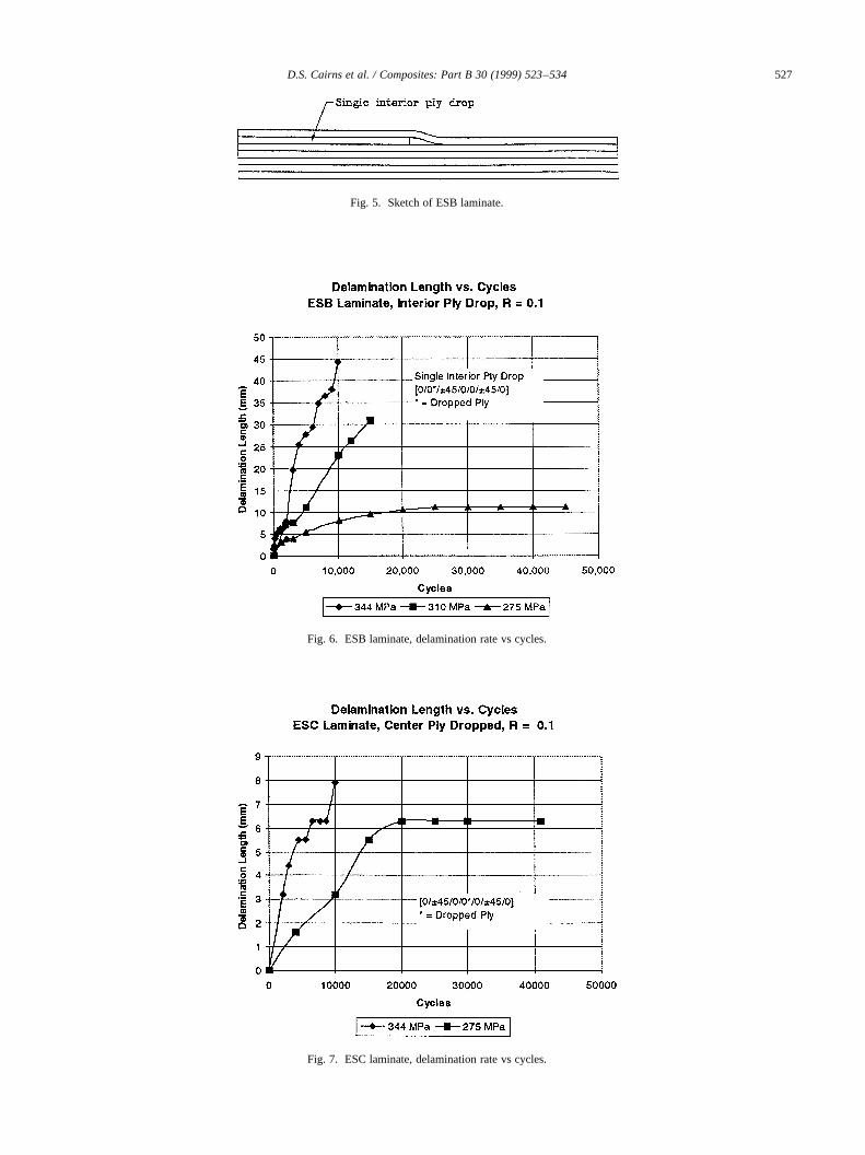
than the ESA laminate. The internal ply has two shearsurfaces to resist delamination and the geometry causes aless severe discontinuity. This was accounted for whencalculating the strain energy release rate (Gc) values. Eq.(1) was divided by two to account for the two individualcrack fronts, consistent with the strength of materialsapproach used in its development. The results for the ESBlaminate show that the threshold stress for forming delami-nation (276 MPa) was more than twice as high as for theESA laminate. Results for the ESC laminate were similar tothe ESB laminate, with only a slight gain in the maximumfatigue stress level. The ESC laminate differs from the ESBlaminate in that the ply drop is in the center of the laminaterather than immediately under the surface, which reducedthe additional bending stress that results as a consequence ofasymmetry. From the graphs of the ESB and ESC laminates,delamination resistance in fatigue can be seen in Figs. 6–7,respectively.
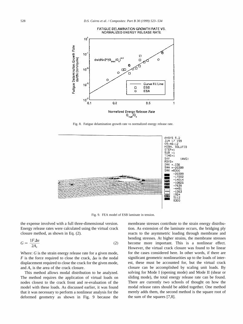
To compare the different laminates on the same scale agraph of fatigue delamination growth rate vs normalizedenergy release rate is given in Fig. 8. This shows thatalthough the strain energy release rate is higher for theESA than for the ESB laminates, when normalized withtheir respectiveGc, the crack growth rate for both laminatescan be correlated with a single relationship. These resultsare extremely encouraging since they imply that the damagegrowth rate for different ply drop configurations may bepredicted from limited testing on a given material.
However, it is noted that the analysis forGc is based on astrength of materials approach from Eq. (1). This may not beadequate for the complicated mixed mode problem. Anonlinear finite element analysis, as shown in Fig. 9, iscurrently being used to investigate this problem. It wasdetermined that a nonlinear analysis was necessary becauseof the membrane/bending coupling in the surrounding plies.This is illustrated by the deformed mesh of Fig. 9. Thebridging plies react out the asymmetric loading via bendingand membrane stresses and the combination is dependent onthe loading. Errors as high as a factor of 2 inGc calculationscan result if the coupling is ignored. Fig. 10 is a detailedcloseup of the ESH interior ply drop. From Fig. 10, it isexpected that, as a consequence of the geometry, mixedmode fracture occurs in the resin rich region and the subse-quent fractured ‘window.’ To account for different modetypes and mixes, the virtual crack closure method describedlater was used for analysis [6].
5. Virtual crack closure method
A finite element analysis (FEA) model was constructed toexamine the initialization, propagation and arrest character-istics of delaminations resulting from plydrops. Threemodels were developed, each corresponding to ESA, ESBand ESC samples with various delamination lengths. Thesemodels used the material and geometric characteristics ofthe glass/polyester coupons listed in Tables 1 and 2. Bothtypes of plies in the coupons (D155 and DB120) aremodeled as 0.508 mm thick. Each plydrop is dropped acrossa 2.54 mm length. The total model length for all samples is91.4 mm long with the plydrop starting at 38.1 mm downthe length. A two-dimensional plane stress model reduced
D.S. Cairns et al. / Composites: Part B 30 (1999) 523–534526
Fig. 3. Model used forGc calculations.
Fig. 4. ESA laminate, delamination rate vs cycles.
D.S. Cairns et al. / Composites: Part B 30 (1999) 523–534 527
Fig. 5. Sketch of ESB laminate.
Fig. 6. ESB laminate, delamination rate vs cycles.
Fig. 7. ESC laminate, delamination rate vs cycles.
the expense involved with a full three-dimensional version.Energy release rates were calculated using the virtual crackclosure method, as shown in Eq. (2).
G� 1FDu2Ac
�2�
Where:G is the strain energy release rate for a given mode,F is the force required to close the crack,Du is the nodaldisplacement required to close the crack for the given mode,andAc is the area of the crack closure.
This method allows modal distribution to be analyzed.The method requires the application of virtual loads onnodes closest to the crack front and re-evaluation of themodel with these loads. As discussed earlier, it was foundthat it was necessary to perform a nonlinear analysis for thedeformed geometry as shown in Fig. 9 because the
membrane stresses contribute to the strain energy distribu-tion. As extension of the laminate occurs, the bridging plyreacts to the asymmetric loading through membrane andbending stresses. At higher strains, the membrane stressesbecome more important. This is a nonlinear effect.However, the virtual crack closure was found to be linearfor the cases considered here. In other words, if there aresignificant geometric nonlinearities up to the loads of inter-est, these must be accounted for, but the virtual crackclosure can be accomplished by scaling unit loads. Bysolving for Mode I (opening mode) and Mode II (shear orsliding mode), the total energy release rate can be found.There are currently two schools of thought on how themodal release rates should be added together. One methodmerely adds them, the second method is the square root ofthe sum of the squares [7,8].
D.S. Cairns et al. / Composites: Part B 30 (1999) 523–534528
Fig. 8. Fatigue delamination growth rate vs normalized energy release rate.
Fig. 9. FEA model of ESB laminate in tension.
Using the virtual crack closure method, ESA, ESB, andESC samples were examined for energy release rates fromcrack initiation and crack arrest using experimental data andloading. Using the accumulated data, it may be possible topredict crack arrest in complex composite structures underfatigue loading. However, it is necessary to first establish arelationship between the energy release rates and the load-ing before reasonable predictions can be made. Using thevirtual crack closure method, in Table 3, the percent ofMode I and II responsible for extending the crack isshown. In this table, the percentage of each mode for thedelamination extending into the thicker section (before theply drop) is given, with the percent strain provided for refer-ence. The analyses were conduced at the experimentally-measured arrest damage sizes. Most of the initiation (smallcrack lengths), was dominated by Mode I crack growth. Thecrack also extended into the thinner section (after the plydrop), the corresponding percentages are given in Table 4.
For this purpose, it is expedient to establish a larger data-base of energy release rates from the virtual crack closuremodels to compare with experimental data. Of particularnote, as the crack grows, the fracture is dominated byMode II strain energy release rates. Hence, initiationappears to occur in the detailed, resin-rich area in Mode I,and progresses to Mode II domination.
6. Laminates ESE, ESF, ESG and ESH
After the first three laminates were studied, it was decidedthat other laminate configurations should be considered. TheESE and ESF laminates were thicker laminates with a single
ply drop. The ESE laminate had an exterior ply drop whilethe ESF laminate had an interior ply drop.
The ESE laminate had a lower delamination growth ratethan the ESA laminate, which had a smaller overall cross-sectional area. TheGc for both the ESA and ESE laminates,along with the ESF laminate compared with the ESB lami-nate were similar.
The ESG and ESH laminate were also thicker in cross-section, but, in an attempt to simulate a potential manufac-turing situation, two plies were dropped at a single locationinstead of one ply. The ESG laminate contained two plydrops on the outside while the ESH laminate containedtwo ply drops on the interior. In both cases, these config-urations behaved poorly compared with their single ply dropcounterparts. During testing of the ESH laminate, the resinrich area ahead of the ply drop was observed to fragmentduring the fatigue test. When the coupon was in the maxi-mum stress part of the fatigue cycle a fracture in the resinpocket through the laminates width was seen. No materialwas left ahead of the ply drop after the first initial cycles.This is illustrated in Fig. 10 and described as the ‘window’in this region.
The ESG laminate with a double external ply drop dela-minated more easily than a single ply drop on the outside.One apparent reason for this is the higher critical strainenergy release rate of the ESA laminate, theGc of theESG laminate was only 1.26 N mm21, while theGc for theESA laminate was 1.89 N mm21. Another reason for thiswas the increased bending moment created by the eccentri-city of having two layers creating the ply drop, as well as thelarger dropped area. A comparison of laminates which
D.S. Cairns et al. / Composites: Part B 30 (1999) 523–534 529
Fig. 10. Sketch of resin rich region in ESH laminate.
Table 3Delamination growth rates for laminates studied (mm/cycle)a
contained internal ply drops is presented in Fig. 11. As notedearlier, the ESH laminate with two interior ply drops had thehighest delamination growth rate. The best configurationwas the ESF laminate, which was a thicker laminate witha single internal ply drop. This laminate has less bendingstresses and better surrounding material load carryingcapability than the comparable ESB and ESC laminates.
7. Attempt at improving delamination resistance
After the previous configurations were tested, methods ofpreventing delamination were studied. The first configura-tion used the ESA laminate as a basis for comparison and asecond configuration used the ESB laminate as a basis. First,random mat fabric was included between the ply drop andthe first continuous zero layer. A second modification iscalled ‘feathering’. In this case, alternating tows were pulledapproximately 13 mm past the adjacent tows to provide aless defined ply drop front and delamination site (Fig. 12).
In two other cases, the ESJ and ESK laminates, innova-tive methods were used to prevent delamination (Fig. 12). Inthe ESJ laminate, ‘Z-Spiking’ was used, which consisted ofremoving the binder from the fabric and driving the fibertows into the lower layers. The transverse strength proper-ties are much lower than the longitudinal properties, provid-ing fiber reinforcement in the thickness direction results inadditional resistance to delamination. The ESK laminateused a 25 mm wide layer of Hysol EA 9309.2NA adhesiveapproximately 0.3 mm thick, between the outer ply drop andthe first continuous zero layer. This adhesive was appliedand was allowed to cure before the resin was injected intothe mold. The theory behind this attempt was that by
D.S. Cairns et al. / Composites: Part B 30 (1999) 523–534530
Fig. 11. Comparison of internal ply drops at 275 MPa.
Fig. 12. Illustrations of feathering, ‘Z-Spiking’, an using Hysol adhesive toprevent delamination.
applying a thin, tough adhesive, delamination initiationwould be resisted. Also the adhesive layer enhances theprocess zone for fracture [9,10]. It is noted that ‘Z-Spiking’and adding local adhesive can also easily be applied in ahand lay-up manufacturing process as well.
8. Results from delamination prevention techniques
Since all of the delamination prevention techniques wereapplied to the same layer configuration as the ESA laminate,the ESA laminate was used as a standard by which the other
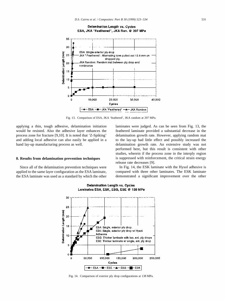
laminates were judged. As can be seen from Fig. 13, thefeathered laminate provided a substantial decrease in thedelamination growth rate. However, applying random matto the lay-up had little effect and possibly increased thedelamination growth rate. An extensive study was notperformed here, but this result is consistent with otherstudies, wherein if the process zone in the interply regionis suppressed with reinforcement, the critical strain energyrelease rate decreases [9].
In Fig. 14, the ESK laminate with the Hysol adhesive iscompared with three other laminates. The ESK laminatedemonstrated a significant improvement over the other
D.S. Cairns et al. / Composites: Part B 30 (1999) 523–534 531
Fig. 13. Comparison of ESA, JKA ‘feathered’, JKA random at 207 MPa.
Fig. 14. Comparison of exterior ply drop configurations at 138 MPa.
configurations tested. The delamination in the ESK laminatedid not initiate until the other laminates had completelydelaminated. The ESJ laminate with ‘Z-Spiking’ is notshown on this graph because there was no delaminationinitiation in more than 200 000 cycles at the same stresslevel. Both ‘Z-spiking’ and the Hysol adhesive delaminationdid not initiate like the other laminates. In both cases, thedelamination initiated at the specimen edges, as expectedfrom previous studies [11–13]. These edge delaminationsoccurred even though the edges of the specimens were care-fully polished. Polishing mitigates, but does not preclude
free-edge effects. The results for the ESJ laminate are illu-strated in Fig. 15. Note that ‘Z-spiking’ has a profoundinfluence on the arrest, presumably resulting from theextensive fiber bridging noted in these samples. The ESBlaminate results, with feathered ply drops, are presented inFig. 16. From Fig. 16, it can be clearly seen for the ESBlaminate with feathered ply drops that the delaminationstarted but stopped, while the ESB material with nofeathering continued to grow until arrest at a much largerdelamination length. In Table 2, the delamination rate forvarious stress levels and laminates ESA through ESK is
D.S. Cairns et al. / Composites: Part B 30 (1999) 523–534532
Fig. 15. ESA vs ESJ ‘Z-Spiked’ laminate.
Fig. 16. ESB vs JKB ‘feathered’ at 275 MPa.
presented. In this table, theR ratio (min stress/max stress)value equals 0.1.
9. Repairing samples previously tested
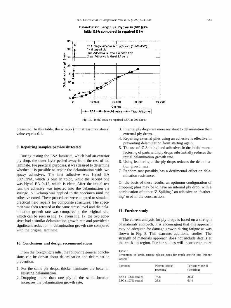
During testing the ESA laminate, which had an exteriorply drop, the outer layer peeled away from the rest of thelaminate. For practical purposes, it was desired to determinewhether it is possible to repair the delamination with twoepoxy adhesives. The first adhesive was Hysol EA9309.2NA, which is blue in color, while the second onewas Hysol EA 9412, which is clear. After the initial testrun, the adhesive was injected into the delamination viasyringe. A C-clamp was applied to the specimen until theadhesive cured. These procedures were adopted to simulatepractical field repairs for composite structures. The speci-men was then retested at the same stress level and the dela-mination growth rate was compared to the original rate,which can be seen in Fig. 17. From Fig. 17, the two adhe-sives had a similar delamination growth rate and provided asignificant reduction in delamination growth rate comparedwith the original laminate.
10. Conclusions and design recommendations
From the foregoing results, the following general conclu-sions can be drawn about delamination and delaminationprevention:
1. For the same ply drops, thicker laminates are better inresisting delamination.
2. Dropping more than one ply at the same locationincreases the delamination growth rate.
3. Internal ply drops are more resistant to delamination thanexternal ply drops.
4. Repairing external plies using an adhesive is effective inpreventing delamination from starting again.
5. The use of ‘Z-Spiking’ and adhesives in the initial manu-facturing of parts with ply drops substantially reduces theinitial delamination growth rate.
6. Using feathering at the ply drops reduces the delamina-tion growth rate.
7. Random mat possibly has a detrimental effect on dela-mination resistance.
On the basis of these results, an optimum configuration ofdropping plies may be to have an internal ply drop, with acombination of either ‘Z-Spiking,’ an adhesive or ‘feather-ing’ used in the construction.
11. Further study
The current analysis for ply drops is based on a strengthof materials approach. it is encouraging that this approachmay be adequate for damage growth during fatigue as wasshown in Fig. 8. This warrants additional studies. Thestrength of materials approach does not include details atthe crack tip region. Further studies will incorporate more
D.S. Cairns et al. / Composites: Part B 30 (1999) 523–534 533
Fig. 17. Initial ESA vs repaired ESA at 206 MPa.
Table 5Percentage of strain energy release rates for crack growth into thinnersectiona
detailed analyses, including the fracture mode type and thefracture mode mix to expand on some of the interestingresults of Tables 2–5. This may explain some of the differ-ences inGc for the various laminates. In particular, thediscrepancies between the DCB and ENF tests need to beexplored.
In the future, determining the effect of spacing of plydrops should be considered. By doing this the number ofplies that can be dropped over a given length can be deter-mined. If the ply drops are too close together, then a resinrich area could possibly form, leading to failure (as in theESH laminate). However, if the ply drops are too far apart,then tapering the thickness may be too gradual and there-fore, non-optimal.
Acknowledgements
This work was supported by the US Department ofEnergy and the State of Montana through the MontanaDOE EPSCoR Program (contract # DE-FC02-91ER75681) and NREL (contract # XF-1-11009-5).
[2] Ramkumar RL, Whitcomb JD. Characterization of Mode I and mixed-mode delamination growth in T300/5208 graphite/epoxy, in delami-nation and debonding of materials. In: Johnson WS, editor. ASTMSTP 876. Philadelphia, PA: American Society for Testing and Mate-rials, ASTM, 1985:315–335.
[3] Rhee KY. Characterization of delamination behavior of unidirectional
graphite/PEEK laminates using cracked lap shear (CLS) specimens.Composite Structures 1994;29:379–382.
[4] Whitney JM, Browning CE, Hoogsteden W. A double cantileverbeam test for characterizing mode i delamination in composites. Jour-nal of Reinforced Plastics and Composites 1982;1:297.
[5] Carlsson LA, Gillespie Jr. JW. On the design and analysis of endnotched flexure (ENF) specimen for Mode II testing. Journal ofComposite Materials 1986;20.
[6] Rybicki EF, Kanninen MF. A finite element calculation of stress-intensity factors by a modified crack closure integral. EngineeringFracture mechanics 1977;9:931–938.
[7] Gong Xiao-Jing, Benzeggagh Malk. Mixed mode interlaminar frac-ture toughness of unidirectional glass/epoxy composites. In: MartinRH, editor. Composite Materials: Fatigue and Fracture — FifthVolume, ASTM STP 1230. Philadelphia, PA: American Society forTesting and Materials, 1995:100–123.
[8] O’Brien TK. Characterization of delamination onset and growth in acomposite laminate. In: Reifsnider KL, editor. Damage in CompositeMaterials, ASTM STP 775. Philadelphia, PA: American Society forTesting and Materials, 1982.
[9] Cairns DS. Prediction of fracture toughness of multi-phasematerials. In: Proceedings of the AIAA/ASME/ASCE/AHS/ASC31st Structures, Structural Dynamics and Materials Conference,April 1990.
[10] Cairns DS. Mixed-mode fracture and toughening in multi-phase mate-rials. In: Proceedings of the ASCE Engineering Mechanics SpecialityConference, 20–22 May 1991.
[11] Wang AS, Crossman FW. Initiation and growth of transverse cracksand edge delamination in composite laminates — Part 1: an energymethod. Journal of Composite Materials 1980;14(1):71–87.
[12] Chan WS, Wang ASD. Free edge delamination characteristics in S2/CE9000 glass/epoxy laminates under static and fatigue loads. In:Composite Materials Fatigue and Fracture, ASTM STP 1012. Phila-delphia, PA: American Society for Testing and Materials, 1989:270–295.
[13] Allix O, Gornet L, Ladeveze P, Leveque D, Delamination predictionby continuum damage mechanics.In: Proceedings of the IUTAMSymposium — Variations of Domains and Free-boundary problems,22–25 April. Paris, France: Kluwer Academic Publishers, 1997.
D.S. Cairns et al. / Composites: Part B 30 (1999) 523–534534