71
Design and Manufacturing of Biologically Inspired Robots Satyandra K. Gupta Department of Mechanical Engineering and Institute for Systems Research University of Maryland

Design and Manufacturing of Biologically Inspired Robots
Satyandra K. Gupta
Department of Mechanical Engineering and Institute for Systems Research
University of Maryland

Bio-Inspired Robots
• Robots that are inspired by an animal, bird, or fish

Why Look to Nature? Land-based Location
Traditional Wheels
Tank treads
Biological Legs
Body Undulation
http://www.nmpproducts.com/pony.htm
http://insects.tamu.edu/extension/youth/bug/bug014.html
http://www.ucmp.berkeley.edu/arthropoda/uniramia/myriapoda.html
http://iowacountyalmanac.blogspot.com/2011/04/worms-crawl-in-worms-crawl-out-ants.html
http://upload.wikimedia.org/wikipedia/commons/1/1b/Lancer_Hubcap.jpg
http://biomech.media.mit.edu/#/portfolio_page/swing-leg-
retraction-in-running/
http://animals.nationalgeographic.com/wallpaper/animals/photos/chee
tahs/cheetah-jump/

Biological Body undulation and fins
Why Look to Nature? Water-based Locomotion
Traditional Propeller
http://commons.wikimedia.org/wiki/File:USS_Chu
rchill_propeller_cropped.jpg
http://cdn1.arkive.org/media/66/66A819D4-4D75-4C84-B2D7-B4D330B94A93/Presentation.Large/European-
eel-swimming.jpg
http://www.arkive.org/rough-toothed-dolphin/steno-bredanensis/image-G131199.html

Why Look to Nature? Air-based Locomotion
Traditional Rotating blades
─ Propeller ─ Turbine engine ─ Helicopter rotor
Rocket
Biological Flapping Wings
http://commons.wikimedia.org/wiki/File:Seagull_flying_(5).jpg
http://www.birdsinflight.net/galleries/gal_1/gal_1.html
http://www.natgeocreative.com/photography/1151183
http://practicallyserious.files.wordpress.com/2012/
06/boeing-747-104-preview.jpg
http://abcnewsradioonline.com/storage/news-
images/GETTY_N_120611_PlanePropeller.jpg
http://www.freeimageslive.co.uk/free_stock_ima
ge/helicopterrotorjpg
http://xcor.com/press/2007/07-01-16_XCOR_begins_methane_engine_testing.html

Capabilities Found in Nature
• High maneuverability • Ability to traverse highly irregular terrain relative to body
size • Ability to function in varied environments • One system capable of several types of motion • Ability to carry objects many times their own weight • Self healing

Applications of Bio-Inspired Robots
• Medical • Reconnaissance and Surveillance • Mine Detection • Detection of Bio-Chemical Weapons • Entertainment • Space Exploration • Pipe Inspection • Environment Monitoring • ….

Some bio-inspired robots have shown up in today’s movies
Spider robot (Minority Report)
Squid robot (Matrix)
Octopus arms (Spiderman 2)
Elephant robot (Star Wars)
Confusion Caused by Robots Depicted in Movies
http://www.zetaminor.com/dvd/dvdreviews/minority.htm http://en.wikipedia.org/wiki/File:2826_DocOck.jpg
http://www.diosnoslibre.com/dnl_viejo/criticas/imagenes/sentinel.jpg http://www.stardestroyer.net/Empire/Tech/Ground/Armour-SW.html
State of the Art
Realizing robots that have capabilities of natural creatures is simply not possible with
today’s technology!

Our Approach
• Simplify ─ Retaining every feature observed in a biological creature
is not useful in in bio-inspired robotics applications ─ Need to identify high value features/characteristics
• Amplify ─ A useful biological characteristics can be amplified in bio-
inspired robots to enhance the performance of simplified design

Robotic Birds: Motivation
• Attributes of fixed wing flight ─ High forward speeds required for generating lift ─ Low maneuverability ─ Difficult to operate in confined spaces
• Attributes of rotary wing flight ─ Low forward speeds and hovering possible ─ High frequency leads to noisy operation
• Attributes of flapping wing flight ─ Low frequency flapping leads to quiet flight ─ Low forward speeds lead to high maneuverability ─ Bridges gap between fixed and rotary wing
http://ucsantacruz.ucnrs.org/peregrine-falcon/
http://en.wikipedia.org/wiki/File:All_Nippon_Airways_Boeing_787-8_Dreamliner_JA801A_OKJ_in_flight.jpg
http://www.aerolink.es/blog/difference-between-fixed-wing-aircraft-and-a-rotary-wing-aircraft/

First Effort: Small Bird (2005-2007)
• Goal: Develop a lightweight and efficient drive mechanism to transmit power from the motor to wings
• Approach ─ Develop a new compliant
mechanism concept ─ Develop multi-piece molds to
realize the light weight compliant mechanism
─ Optimize shape ─ Incorporate multi-functional
materials for dissipating heat D. Mueller, H.A. Bruck, and S.K. Gupta. Measurement of thrust and lift forces associated with drag of compliant flapping wing for micro air vehicles using a new test stand design. Experimental Mechanics, 50(6):725–735, 2010 W. Bejgerowski, A. Ananthanarayanan, D. Mueller, and S.K. Gupta. Integrated product and process design for a flapping wing drive-mechanism. ASME Journal of Mechanical Design, 131, 2009 W. Bejgerowski, S.K. Gupta, and H.A. Bruck. A systematic approach for designing multi-functional thermally conducting polymer structures with embedded actuators. ASME Journal of Mechanical Design, 131(11): 111009, 2009

Small Bird
First Flight in 2007
Weight: 9.7 g (excluding battery) Wing Span: 34.3 cm Flapping Frequency: 12.1 Hz Pay Load Capability: 5.7 g (including battery)

Big Bird with Folding Wing (2007-2008)
• Goal: Generate static lift by folding wings during up-strokes
• Approach ─ Increase the size of the platform to
enhance payload capacity ─ Incorporate on-way joints in wings to
facilitate passive wing folding in up-stroke
─ Develop new joint designs based on the distributed compliance concept
─ Optimize wing design
D. Mueller, J. Gerdes, and S.K. Gupta. Incorporation of passive wing folding in flapping wing miniature air vehicles. ASME Mechanism and Robotics Conference, San Diego, 2009
Weight: 29.9 g (excluding battery) Wing Span: 57.2 cm Flapping Frequency: 4.5 Hz Pay Load Capability: 17.0 g (including battery)
Flight in 2008

Jumbo Bird (2009-2010)
• Goal: Increase payload capacity of the robotic bird
• Approach ─ Develop a new transmission
mechanism based on multi-material compliant mechanism concepts
─ Develop in-mold assembly process for realizing transmission mechanism
─ Concurrently optimize product and process parameters
─ Optimize wing designs J.W. Gerdes, K.C. Cellon, H.A. Bruck, S.K. Gupta. Characterization of the mechanics of compliant wing designs for flapping-wing miniature air vehicles. Experimental Mechanics, Accepted 2013 W. Bejgerowski, J.W. Gerdes, S.K. Gupta, and H.A. Bruck. Design and fabrication of miniature compliant hinges for multi-material compliant mechanisms. International Journal of Advanced Manufacturing Technology, 57(5):437-452, 2011 W. Bejgerowski, J.W. Gerdes, S.K. Gupta, H.A. Bruck, and S. Wilkerson. Design and fabrication of a multi-material compliant flapping wing drive mechanism for miniature air vehicles. ASME Mechanism and Robotics Conference, Montreal, Canada, August 2010
Multi-Material Drive Frame
Weight: 38.0 g (excluding battery) Wing Span: 63.5 cm Flapping Frequency: 6.1 Hz Pay Load Capability: 33.0 g (including battery)

Video
https://www.youtube.com/watch?v=qJmeFKf0l-g

In-Mold Assembly: A New manufacturing Approach
• Introduce multiple materials in the mold sequentially ─ Change mold cavity between different molding stages
• Perform assembly and fabrication inside the mold ─ Mold acts as fabrication tool and assembly device
• Eliminate post-molding assembly ─ Attractive in markets where labor cost is high
This two degree of freedom gimbal comes out of mold fully
assembled (Work done at UMD)
Presence of an already molded component fundamentally changes the thermomechanical characteristics of the mold in the molding process

In-Mold Assembly Methods
Final part The part has to be removed completely from the first mold and then
assembled into the second mold.
First stage Injection
After the first mold stage, the part has to be dismantled…
Second stage Injection
…and has to be assembled into the mold of the second mold stage
Cavity shape after completing first stage
Cavity shape before starting second stage
(a) moving a mold piece (b) removing partition (c) changing a mold piece
Cavity shapes need to change during molding before injecting second stage
Overmolding
Morphing Cavity

Spherical joint
In-Mold Assembled Joints
• We have developed mold design templates for successfully realizing revolute, prismatic, spherical, and universal joints using in-mold assembly
• We have developed methods to control shrinkage of the second stage part to provide the adequate joint clearances
Prismatic joint
Rotor structure
Revolute joints
Rigid Body Joints
Compliant Clip
Compliant members
Compliant Joints
• We have developed mold design templates for realizing variety of 1 DOF and 2 DOF compliant joints using in-mold assembly
• We have characterized the influence of interface geometry on the interface strength to optimize joint performance
A.K. Priyadarshi, S.K. Gupta, R. Gouker, F. Krebs, M. Shroeder, and S. Warth. Manufacturing multi-material articulated plastic products using in-mold assembly. International Journal of Advanced Manufacturing Technology, 32(3-4):350-365, March 2007.
R.M. Gouker, S.K. Gupta, H.A. Bruck, and T. Holzschuh. Manufacturing of multi-material compliant mechanisms using multi-material molding. International Journal of Advanced Manufacturing Technology, 30(11-12):1049-1075, 2006.
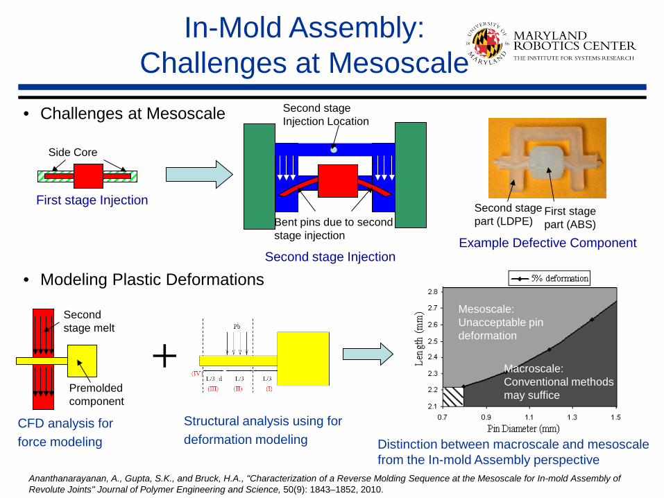
Mesoscale: Unacceptable pin deformation
Macroscale: Conventional methods may suffice
• Challenges at Mesoscale
• Modeling Plastic Deformations
First stage Injection
Second stage Injection
First stage part (ABS)
Second stage part (LDPE)
Example Defective Component
Side Core
In-Mold Assembly: Challenges at Mesoscale
Second stage Injection Location
Bent pins due to second stage injection
CFD analysis for force modeling
Premolded component
Second stage melt
Structural analysis using for deformation modeling Distinction between macroscale and mesoscale
from the In-mold Assembly perspective Ananthanarayanan, A., Gupta, S.K., and Bruck, H.A., "Characterization of a Reverse Molding Sequence at the Mesoscale for In-mold Assembly of Revolute Joints" Journal of Polymer Engineering and Science, 50(9): 1843–1852, 2010.
+
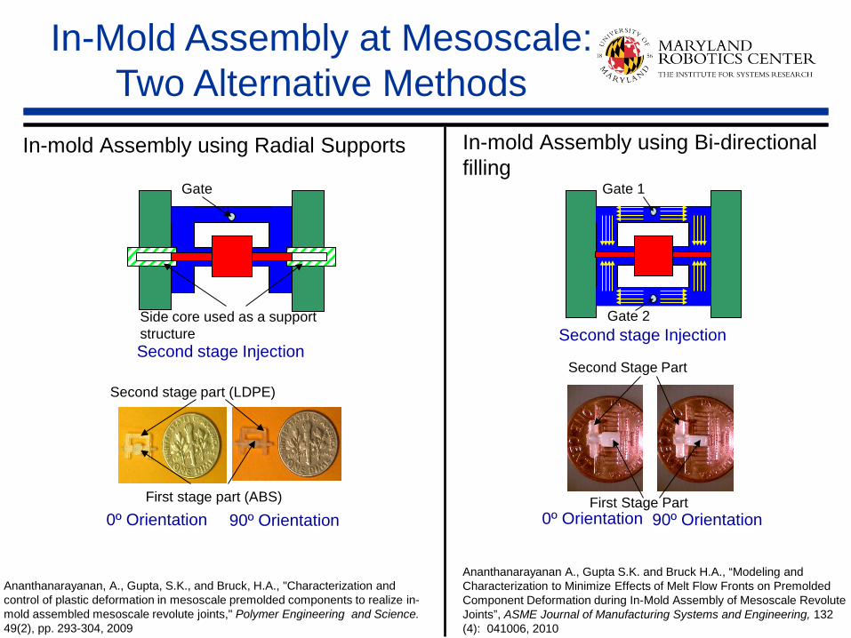
In-Mold Assembly at Mesoscale: Two Alternative Methods
Gate 1
Second stage Injection
First Stage Part
Second Stage Part
0º Orientation 90º Orientation
Side core used as a support structure
Gate
Second stage part (LDPE)
Gate 2
0º Orientation 90º Orientation First stage part (ABS)
Second stage Injection
In-mold Assembly using Radial Supports In-mold Assembly using Bi-directional filling
Ananthanarayanan, A., Gupta, S.K., and Bruck, H.A., "Characterization and control of plastic deformation in mesoscale premolded components to realize in-mold assembled mesoscale revolute joints," Polymer Engineering and Science. 49(2), pp. 293-304, 2009
Ananthanarayanan A., Gupta S.K. and Bruck H.A., “Modeling and Characterization to Minimize Effects of Melt Flow Fronts on Premolded Component Deformation during In-Mold Assembly of Mesoscale Revolute Joints”, ASME Journal of Manufacturing Systems and Engineering, 132 (4): 041006, 2010

Step 1: Mold Assembly consisting of Metal inserts Step 2: Single Shot Injection Step 3 (a): Removal of Side Cores
Step 3 (b): Removal of Side Cores Step 4: Ejection Two different orientations of Neurosurgical Robot Structure
In-mold Assembly at Mesoscale using Insert Molding
A. Ananthanarayanan, L. Ehrlich, J.P. Desai, and S.K. Gupta. Design of revolute joints for in-mold assembly using insert molding. ASME Journal of Mechanical Design, 133(12):121010, Dec 2011

5 mm
Hinge displacement due to lack of positioning features
Challenges in In-Mold Assembly of Meso-Scale Compliant Joints
• Hinge has to provide the desired range of motion
• Structure has to transfer loads • Materials need to be connected • Hinge has to be accurately positioned
for in-mold assembly • Miniature scale of the mechanism can
impose additional space constraints Link fracture examples
Hinge fracture examples
5 mm
1 mm
5 mm
Anchoring feature shearing Anchoring feature plastic deformation

Identification of Hinge Geometry
• Necessary hinge geometries ─ Flexing section
Enable rotation Transfer load Flash prevention
Fatigue resistance ─ Positioning feature
Positioning inside 2nd stage mold ─ Interlocking features
Hinge anchoring in the link Load transfer
• Encapsulating link volume
X-Y:
X-Z:
X-Y:
Y-Z:
X-Y:
Y-Z:
X-Y:
X
Y
Z

Identification of Hinge Geometry (Cont.)
• Parametric model for optimization ─ Number of parameters: 15 ─ Number of constraints: 7
Feature Symbol Description
Hinge Active
Section
tA Thickness (symm. wrt. rot. axis) bA Breadth (along rot. axis) LA Length (for the range of motion) rHIN Hinge arc radius
Hinge Embedded
Section
LEHi Length (along LA direction) hIP Interlocking protrusion height bIP Interlocking protrusion breadth LIP Interlocking protrusion length rIP Interlocking protrusion radius bIV Interlocking void breadth tIV Thickness around interlocking void
hPOS Positioning protrusion height rPOS Positioning protrusion radius
Link Connection
LEL Hinge encapsulating length bEL Encapsulating breadth tEL Encapsulating thickness rEL Link ending radius
Fn# Formula Description g1 tA<<bA Define the rotation axis g2 tA>tAMIN Constrain the remaining DOF g3 AA>σA
MAX/σT Load-guided cross-section area: AA=tA*bA
g4 LEH<LEL<LEMAX Maximum embedded lengths (functional
space constraint)
g5 AITOT ≥ AA
Minimum total interlocking area AI
TOT=2*[(LIP*hIP)+(tA*bIP)]+(bIV*tA) g6 bIP ≥ hIP Prevent shearing of interlocking protrusion g7 tA,tIV,rIP,rPOS≥tTOOL
MIN Size constraints from tool size
Hinge parametric model: Parameters
Hinge parametric model: Constraints

Parametric Optimization Mechanism Design Level
• Mechanism Design Analysis: ─ Kinematic analysis (ADAMS)
─ Finite element analysis (ProMechanica)
• Results:
Kinematic Simulation
Model
Drive Mechanism
Shape
Experimental Forces
Boundary Conditions
Estimate Force
Distribution
Parametric Model
Calculate Stress Distribution
Final Mechanism Design
Modify Elements with Exceeded
Stresses
Strength Constraints
Satisfactory Factor of Safety?
No
Yes
Manufacturability Constraints
New Model
Constant Velocity (BC)
Thrust (BC)
Lift (BC)
Reaction Forces (Outputs)
Lift (BC)
Reaction Forces (Output)
A B C
D E
F
Component Applied to Unit Value X A N -1.159 Y A N -32.767 Z A N -1.559 X C N 0.026 Y C N 31.141
Mechanism Design Optimization Flowchart
Variable Unit Value Rocker thickness mm 2.1 Rocker breadth mm 2.5 Wing arm thickness mm 2.5 Wing arm breadth mm 5.1 Hinge encapsulation thickness mm 7.5 Hinge encapsulation breadth mm 5.0

Parametric Optimization Hinge Design Level
• Optimization approach:
• Results:
Objective Functions
Process Cost Part Weight (Volume)
Constraints Functional
Space Load Transfer
Range of Motion
Process
Molding Feature Size
Design Features
Hinge and Link-bar Connection Hinge Geometry
Variables Hinge Design
Parametric Model
Design Optimization
LA LEH1 LEH2
LIP
rIP rPOS hPOS
bIP
tIV
tA
hIP bA
bIV
rHIN
LDPE
HIPP
Variable Symbol Value Hinge thickness tA 1.10 Hinge breadth bA 5.59 Hinge length LA 0.51 Interlocking protrusion height hIP 0.65 Interlocking protrusion breadth bIP 0.80 Interlocking protrusion length LIP 6.94 Thickness around interlocking void tIV 0.80
Variable Symbol Value Hinge thickness tA 0.79 Hinge length LA 1.52 Hinge radius hHIN 1.27 Interlocking protrusion length LIP 5.59
Hinge Design Parametric Model
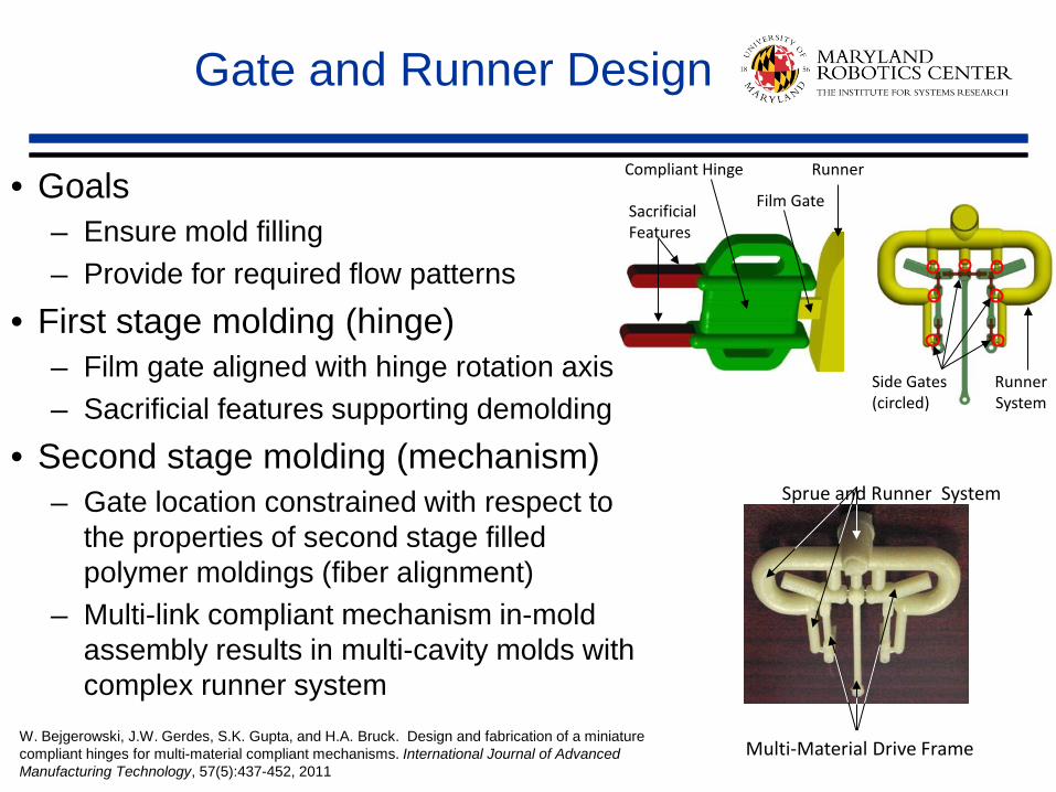
Gate and Runner Design
• Goals ─ Ensure mold filling ─ Provide for required flow patterns
• First stage molding (hinge) ─ Film gate aligned with hinge rotation axis ─ Sacrificial features supporting demolding
• Second stage molding (mechanism) ─ Gate location constrained with respect to
the properties of second stage filled polymer moldings (fiber alignment)
─ Multi-link compliant mechanism in-mold assembly results in multi-cavity molds with complex runner system
Sacrificial Features
Compliant Hinge
Film Gate
Runner
Side Gates (circled)
Runner System
W. Bejgerowski, J.W. Gerdes, S.K. Gupta, and H.A. Bruck. Design and fabrication of a miniature compliant hinges for multi-material compliant mechanisms. International Journal of Advanced Manufacturing Technology, 57(5):437-452, 2011
Sprue and Runner System
Multi-Material Drive Frame

Actuated Articulated Miniature Robot After In-Mold Assembly
• Successful actuation of each joint of the robot in both directions • Generation of sufficient force to smoothly actuate the joint
A. Ananthanarayanan, L. Ehrlich, M. Ho, J.P. Desai and S.K. Gupta. Embedding Shape Memory Allow Actuators in Miniature Articulating Polymer Structures Using In-Mold Assembly. North American Manufacturing Research Conference, Notre Dame, IN, June 2012

Thermally Conducting Polymers
• Low heat dissipation from actuators embedded in structures of traditional unfilled polymers ─ Excessive heat can overheat and damage the structure
• Can emerging thermally conductive polymer composites help to overcome this issue? Minimally Invasive Neurosurgical
Intracranial Robot (MINIR)
UMD “Small bird” Micro Air Vehicle
Measure Units Grilamid L16 NJ-6000 TC
Density kg·m−3 1010 1610
Thermal Conductivity W·m-1·K-1 0.22 11
Tensile Strength MPa 42 110
Elongation at Break % 275 1.9
Flexural Modulus GPa 1.3 22.2
Flexural Strength MPa 59 109
Melt Temperature Range °C 190 to 270 260 to 277
Adding function to part structure – heat dissipation

Embedding DC Motor
• In-mold assembled samples:
• Motor temperature measurement: ─ Constant load applied to motor shaft ─ Power generation (1.5W) controlled by voltage and current
• Results: ─ Unfilled Nylon12 (Grilamid L16): 96.0 C ─ Filled Nylon12 (NJ-6000 TC): 65.5 C Motor embedded in unfilled polymer
runs 46% hotter! W. Bejgerowski, S.K. Gupta, and H.A. Bruck. A systematic approach for designing multi-functional thermally conducting polymer structures with embedded actuators. ASME Journal of Mechanical Design, 131(11): 111009, 2009

Advanced Manufacturing Summary
• In-mold assembly enables large design space ─ Bio-compatible polymers ─ Parts with small features
• In-mold assembly enables realization of joints to transfer power and motion ─ Revolute, Prismatic, Spherical
• In-mold assembly enables embedding of prefabricated components in the structure without damaging them ─ Actuators, Batteries, Sensors
Robotics
Injection Molding
Advanced Polymer Composites
3D Printing
In-mold assembly brings together many exciting developments in
manufacturing

Robotic Birds: Observations
Wings undergo through significant deformation!

Main Limitations of Previous Designs
• Wing velocity has significant influence on wing deformation • No way for us to control wing deformation by controlling
velocity in previous designs ─ We can only control flapping frequency
Need to control wing shape by controlling wing velocity

New Direction in Research
• Develop robotic bird with Independently Controllable and Programmable Wings to understand bio-inspired flight ─ Understand the influence of wing velocity on lift and
thrust forces ─ Optimize performance ─ Aerobatic maneuvers

Our Inspiration: Raven
Raven Specs Length: 24 to 26 in (61
to 66 cm) Wingspan: 45.6 to 56.4 in
(1.2 to 1.4 m) Weight: 2.3 lbs (1.3 kg)
Flapping frequency:
4-6 Hz
http://www.birdsource.org/gbbc/gallery/2007/comrav_tucker-cr_nm.jpg/image_preview

Research Challenges
• Independent wing control means two independent actuators → heavier platform
• Wing and motor must be properly matched to enable flight ─ Optimal wing design ─ Run motors at optimal operating point
• Difficult problem to model at system level
Flapping Profile
Compliant Wings
Unsteady Aerodynamics
Motor Dynamics
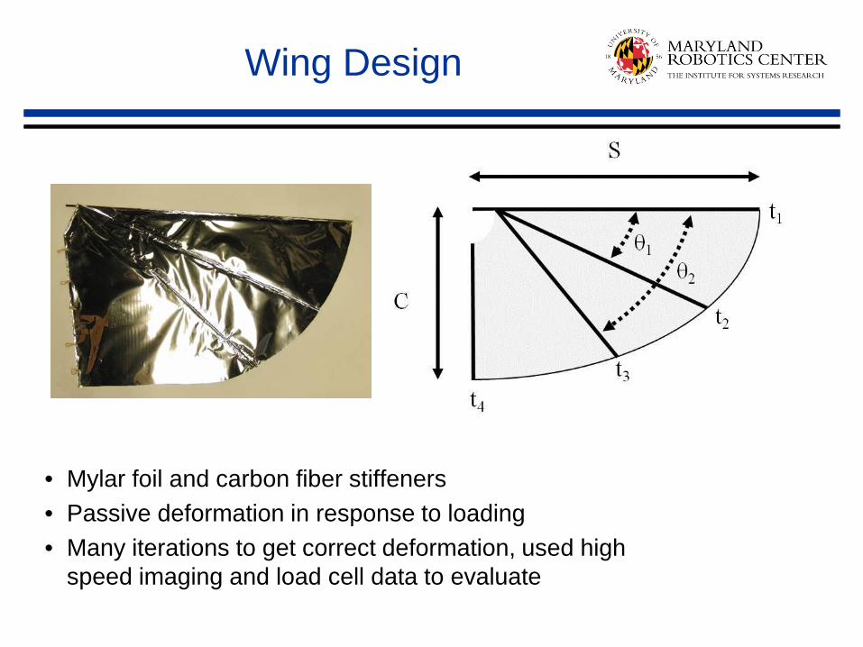
Wing Design
• Mylar foil and carbon fiber stiffeners • Passive deformation in response to loading • Many iterations to get correct deformation, used high
speed imaging and load cell data to evaluate

Wing Sizing
Robo Raven wing area and wingspan (red) compared to 33 other birds (blue)

Wing Design
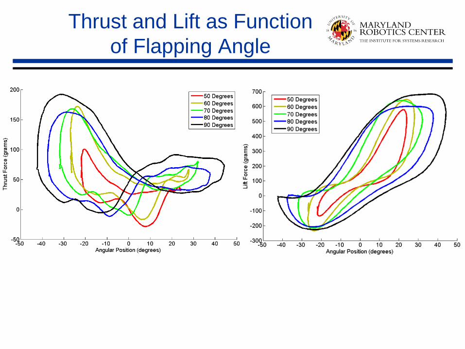
Thrust and Lift as Function of Flapping Angle

Digital Image Correlation to Relate Wing Deformation to Performance

Selected Wing
Para-meter
Value
S 23.85”
C 14.25”
t1 0.125”
t2 0.064”
t3 0.064”
t4 0.064”
θ1 20.5°
θ2 43°
Flapping Range: 70 degrees Flapping Frequency: 4 Hz
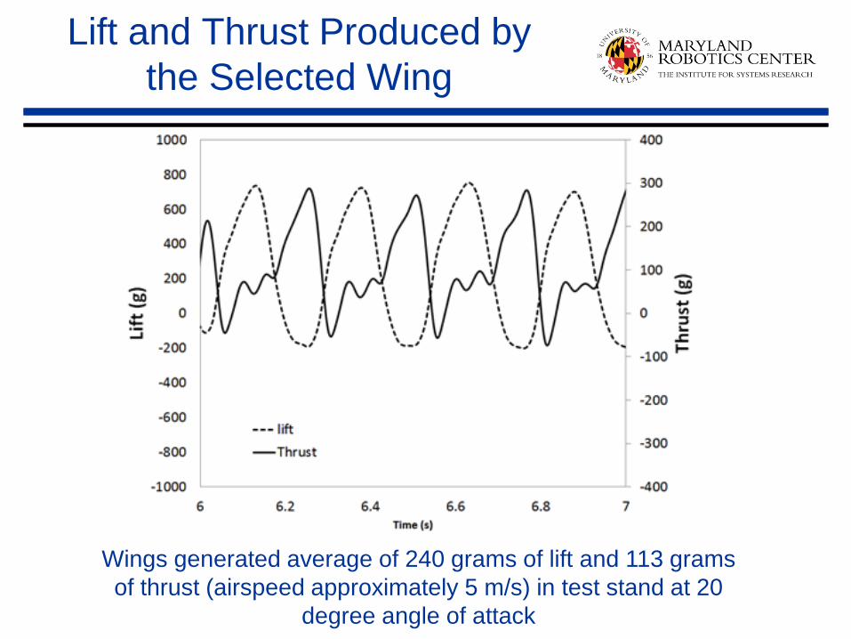
Lift and Thrust Produced by the Selected Wing
Wings generated average of 240 grams of lift and 113 grams of thrust (airspeed approximately 5 m/s) in test stand at 20
degree angle of attack

Manufacturing
• 2 motors and a bigger battery → heavy MAV • 3D printing and laser cutting
─ Lightweight parts ─ Easy and quick to manufacture and make changes ─ Used to house the motors and provide structure along with carbon
fiber tubes for the frame High strength nylon Ultem (3D printing) and Delrin (laser cutter)
• Mylar/carbon fiber wings ─ Strong and lightweight

Result: Robo Raven Flying Prototype
• Independently controlled wings capable of arbitrary gaits • New maneuvers possible: flips, dives, gliding • Vehicle weight = 290g • Flight speed = 6.7 m/s • Endurance = 4 minutes 45 seconds

Comparison with Ravens
Raven Specs Robo Raven Specs Length: 24 to 26 in (61
to 66 cm) Length: 24 in (61 cm)
Wingspan: 45.6 to 56.4 in (1.2 to 1.4 m)
Wingspan: 44 in (1.1 m)
Weight: 2.3 lbs (1.3 kg) Weight (w/battery, w/out):
(291.6 g, 264.5 g)
Flapping frequency:
4-6 Hz Flapping frequency:
4 Hz

Flight Power Comparison
Flight cost of 33 species of birds J. J. Videler, Avian Flight. Oxford: Oxford University Press 2005.

Robo Raven Videos
https://www.youtube.com/watch?v=mjOWpwbnmTw
https://www.youtube.com/watch?v=XhsXul39DZg

• Goal: Use on-board solar cells to charge batteries for Robo Raven
• Approach ─ Develop a layered manufacturing
process for making multifunctional wings with integrated solar cells
─ Design wings to incorporate solar cells
─ Develop models to predict system performance
Robo Raven with Solar Cell Integrated Wings
Robo Raven III Video https://www.youtube.com/watch?v=t1_mPe8Y0V4

R2G2: Robot with Rectilinear Gait
for Ground Operations

Operational Needs in Search, Rescue, Recovery Missions
• Terrain Versatility ─ Rubble, Grass, Carpet
• Small Cross Section ─ To enable access to narrow passages
• High Forward Velocity ─ Human Walking Speed
• Energy Efficiency
[www.ibtimes.com] [www.sodahead.com]
[www.firedepartment.org]
[www.955sold.com]
[www.elliottgarber.com]

Why take Inspiration from Snakes?
• Snake-inspired robots can traverse many difficult terrain types ─ Tight enclosed spaces such as pipes ─ Rough terrains
• Snake-inspired robots can operate in hazardous environments ─ Unstable buildings
• Snake-inspired robots possess redundant structures ─ May continue to function when a small
portion is damaged ─ Shape can conform to terrestrial
obstacles
[www.sciencenews.org]
[www. sciencemusings.com]
[www.californiaherps.com/snakes]

Types of Snake Locomotion
• Serpentine ─ Body moves forward along the
S-shaped path while the head lays out additional curves
• Rectilinear ─ Snake moves forward along a
straight line through extensions and contractions of the body
• Sidewinding ─ Snake leaves a series of
parallel tracks inclined at an angle to the path of motion
• Concertina ─ Used by snakes when confined
within a channel Rectilinear Locomotion
[Gray 1968]
Serpentine Locomotion [Dowling 1997]
Different gaits lead to different designs

Exaggerated Rectilinear Gait for High Speed Motion
• Simultaneously expands and contracts all the internal segments during the gait cycle
• Employs an anchoring mechanism to periodically restrict movement of the ends
• Anchoring mechanism provides variable traction to support operation on multiple terrains
(1)
(3)
(4)
(2)
A New Rectilinear Gait Concept
Direction of Motion

Gait for Turning
• No linear expansion utilized, only rotations between the internal segments
• Robot’s length curls toward the intended direction of turn
• Global motion described as the robot spinning about its center segment
A New Rectilinear Gait Concept (Cont.)
(1)
(3)
(4)
(2)
Side View
Side View
Top View
Top View

Implications of the New Concept on Operational Needs
Terrain Versatility Basic characteristics of rectilinear gait
Traction Variable force anchoring
Small Cross Section New mechanism design
High Speed Fast body extension and contraction
Energy Efficiency Design new gaits for different missions

Pivot Input Link
Extension Input Link Output Link
Parallel Mechanism
x y
z
Drive Mechanism Design

Selectable Friction Pads
x y
z
θFA
Friction Anchor Design

Prototype Robot: R2G2
• Physical Parameters: ─ Cross Section: 70 x 70 mm ─ Length (Contracted): 1000 mm ─ Length (Extended): 1385 mm ─ Weight: 2.5 kg
• Power Plant: ─ (4) Modules ((16) HS-7950TH Motors) ─ (2) Terminal Friction Anchors ─ (1) 7.4V 2100mAh Pro Lite LiPo Battery
• Control: ─ Arduino Mega Microcontroller ─ Radio Control via RC Relays
J.K. Hopkins and S.K. Gupta. Design and modeling of a new drive system and exaggerated rectilinear-gait for a snake-inspired robot. ASME Journal of Mechanism and Robotics, Accepted for publication.

Prototype Robot Comparison
Robots with expansion gait
Robots with wheels
Robots with vert. wave gait
Energy Efficient Gaits
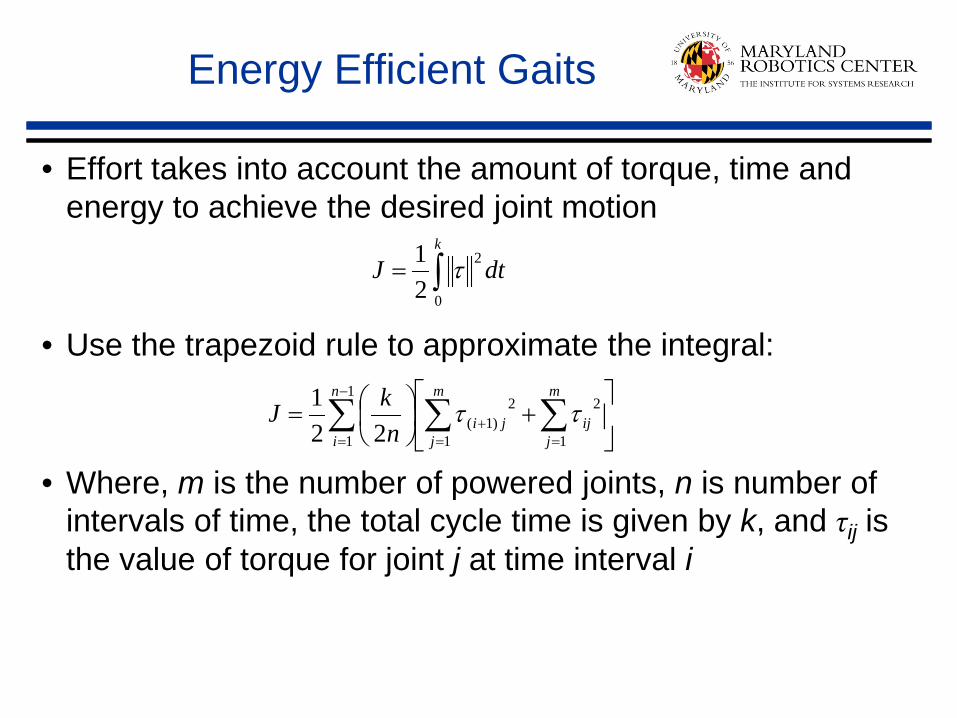
• Effort takes into account the amount of torque, time and energy to achieve the desired joint motion
• Use the trapezoid rule to approximate the integral:
• Where, m is the number of powered joints, n is number of
intervals of time, the total cycle time is given by k, and τij is the value of torque for joint j at time interval i
∫=k
dtJ0
2
21 τ
∑ ∑∑−
= ==+
+
=
1
1 1
2
1
2)1(22
1 n
i
m
jij
m
jjin
kJ ττ

Low Effort Rectilinear Gait
• Modified the gait to use anchors only on the ends of the robot platform
• In theory the gait yields lower effort per cycle than typical vertical wave gait ─ No more than two joints are
actuated at any given time ─ Internal links remain in
contact with the terrain

Experimental Trials for Energy Efficient Gait
• Each expansion-type gait executed three trial runs for a given distance
• The battery charger data used to estimate energy drain per trial
• Energy drain used to estimate energy consumed per meter traveled
Gait Type
Trial Runs
Charge Time (s)
Energy (J) per m
Low Effort
1 387 2864
2 466 3448
3 419 3100
High Speed
7 640 4736
8 588 4351
9 653 4832

High Traction Gait
• Friction anchor alone may not be effective on difficult terrains ─ Rugged, hard terrains ─ Smooth, soft terrains
• Robot extends its forward half first followed by the aft half to provide additional traction
• Gait dynamics model used to confirm higher traction potential compared to high speed gait
Exaggerated Rectilinear Gait for High Traction Motion
Direction of Motion

Robo Terp
• Goal: Develop a legged amphibious robot for splash free swimming
• Approach ─ Incorporate compliance in legs
to assist swimming ─ Optimize leg design ─ Develop new gaits for walking,
swimming, and transitioning ─ Develop sensors for
autonomous gait transitions
Robo Terp Video https://www.youtube.com/watch?v=mo4hs287His

SCALE Bot
• Goal: Develop a low-cost robot capable of autonomously climbing stairs using on-board sensing and computation
• Approach ─ Develop twelve degree of freedom legged
robot using off the shelf actuators, sensors, and controllers
─ Design body to be machinable using only laser cutter
─ Develop parameterized gaits to climb stairs ─ Develop algorithms to process sensor data to
select gait parameters
SCALE Bot Video http://www.youtube.com/watch?v=BDSzO8mhOuY

Summary
• Realizing bio-inspired robots is very challenging • Simplify-Amplify approach works in practice
• It is important to carefully select features from biological source
• Realizing bio-inspired robots often requires new manufacturing approaches
• We have developed unique capabilities to combine design, modeling & simulation, and manufacturing to realize novel robot concepts

Acknowledgements
Students • Arvind Ananthanarayanan • Eli Barnett • Wojciech Bejgerowski • Leicester Ehrlich • John Gerdes • Adrian Greisinger • James Hopkins • Johannes Kempny • Gregory Krummel • Dominik Mueller • Savannah Nolen • Ariel Perez-Rosado • Luke Roberts • Andrew Vogel
Collaborators • Hugh Bruck and Jaydev Desai
Sponsors • AFOSR, ARO, NIH, and NSF


![Shape memory alloy-based small crawling robots inspired by ... · material for many biologically inspired robots such as worm-like robots [12], the bending actuation of an IPMC is](https://static.documents.pub/doc/80x56/5fbd02e298ad5d4fd41f1ccb/shape-memory-alloy-based-small-crawling-robots-inspired-by-material-for-many.jpg)


