3112 IEEE TRANSACTIONS ON ANTENNAS AND PROPAGATION, VOL. 56, NO. 10, OCTOBER 2008
Design and Measurement of Reconfigurable Millimeter Wave Reflectarray Cells With Nematic
Liquid Crystal Wenfei Hu, Member, IEEE, Robert Cahill, Jose A. Encinar, Member, IEEE, Raymond Dickie, Harold Gamble,
Vincent Fusco, Fellow, IEEE, and Norman Grant
Abstract—Numerical simulations are used to study the electromagnetic scattering from phase agile microstrip reflectarray cells which exploit the voltage controlled dielectric anisotropy property of nematic state liquid crystals (LCs). In the computer model two arrays of equal size elements constructed on a 15/zm thick tuneable LC layer were designed to operate at center frequencies of 102 GHz and 130 GHz. Micromachining processes based on the metallization of quartz/silicon wafers and an industry compatible LCD packaging technique were employed to fabricate the grounded periodic structures. The loss and the phase of the reflected signals were measured using a quasi-optical test bench with the reflectarray inserted at the beam waist of the imaged Gaussian beam, thus eliminating some of the major problems associated with traditional free-space characterization at these frequencies. By applying a low frequency AC bias voltage of 10 V, a 165° phase shift with a loss 4.5-6.4 dB at 102 GHz and 130° phase shift with a loss variation between 4.3-7 dB at 130 GHz was obtained. The experimental results are shown to be in close agreement with the computer model.
R ECENTLY it has been shown that it is possible to modulate the phase of signals in the microwave and mm wave
bands by exploiting the physical response of LC molecules to an applied electric field. Several prototype devices based on liquid crystal substrate with tunable permittivity have been reported. These include a reconfigurable bandpass frequency selective surface (FSS) [1], an electronically steered beam reflectarray which is center fed by an open ended waveguide [2], and an offset horn fed reflectarray with switchable sum/difference radiation patterns, i.e., monopulse operation [3]. Phase shifter technology based on this approach is potentially attractive because of the low cost, the simplicity of the biasing arrange-
Manuscript received March 10, 2008; revised May 11, 2008. Current version published October 3,2008. This work is supported by the Engineering and Physical Sciences Research Council under Grant EP/C00230X/1.
W. Hu, R. Cahill, R. Dickie, and V. Fusco are with the Institute of Electronics, Communications and Information Technology, Queen's University of Belfast, Belfast BT3 9DT, Ireland (e-mail: [email protected]).
J. A. Encinar is with the Electromagnetism and Circuit Theory Department, Universidad Politecnica de Madrid, 28040 Madrid, Spain.
H. Gamble is with the Northern Ireland Semiconductor Research Centre, Queen's University Belfast, Belfast BT9 5AH, Ireland.
N. Grant is with the EADS Astrium Earth Observation Navigation and Science Directorate, Portsmouth P03 5PU, U.K.
Digital Object Identifier 10.1109/TAP.2008.929460
ment, the ease of fabrication and integration, and unlike semiconductor devices no limitation is imposed on the upper operating frequency. Moreover the dielectric absorption loss of LC reduces with frequency [4] and switching speed is faster due to the reduction in the physical thickness of the LC layer. In this paper we describe the design of prototype reflectarray structures which operate at frequencies above 100 GHz. The scattering parameters were computed by modelling the structure as an infinite array of identical size patch elements using a unit cell with appropriate boundary conditions. In the simulator the patches are placed on a 300 /xm thick quartz superstrate and the 15 ttm gap between the array and the ground plane is filled with tunable LC material. The permittivity value of the tunable layer was varied between e// — 3.2 (biased state) and e± — 2.8 (0 V state), and for each state tan 6 — 0.02 was used in the computer model. These values were obtained previously for Merck BL037 LC mixture [5], by data fitting computed results to experimental data over the frequency range 110-170 GHz [1]. The construction method that was used to fabricate the two structures is described and the amplitude and phase of the reflected signals, which were obtained from a novel quasi-optical measurement set up, are shown to be in close agreement with numerical results.
II. DESIGN AND NUMERICAL RESULTS
Fig. 1 depicts a schematic plot of the tunable unit cell and the orientation of the liquid crystals in the unbiased and biased states. The director of the LC molecules is orientated in the direction of the wafer surface by an appropriate surface treatment such as a thin brushed polymer coating. The torque necessary to rotate the molecules perpendicular to the surface, as shown in Fig. 1, is obtained by applying a low frequency AC voltage between the patch and the ground plane, to create a variable z-di-rected electrostatic field in the substrate region. As a result, the permittivity of the tunable substrate varies between two values e// (biased state) and e± (0 V state) and therefore the dielectric anisotropy is given by Aeeff = e// - e± [6]. Note that the effective dielectric constant is insensitive to the orientation of the electric field in the X Y plane, and therefore it is valid for any polarization and angle of incidence of the impinging wave. Thus the resonant frequency of the microstrip patches and hence the reflection phase and amplitude of the scattering wave can be controlled by applying a bias voltage. In this paper we only show the extreme phase states which correspond to bias voltage of 0
V and 10 V because the difference between these two values
HU et al: DESIGN AND MEASUREMENT OF RECONFIGURABLE MILLIMETER WAVE REFLECTARRAY CELLS 3113
provides the maximum dynamic phase range of the cell at a given frequency. Between these two states the change in reflection phase is a non linear function of the applied voltage [7]. For applications above 100 GHz the choice of the superstrate material is important for two reasons. Firstly accurate permittivity and loss tangent values of the wafer material must be available, and secondly the wafer must have an optically smooth surface with a uniform thickness. This will ensure good surface alignment and produce a uniform gap (TLC) between the patch array and the ground plane. Quartz was selected because it fulfils the criteria (er = 3.78, tan 6 — 0.002 [1]) and moreover this material is space qualified. Copper coated Si was used as a ground plane because this satisfies the mechanical requirements. CST microwave studio was used to design and simulate the scattering behavior of the arrays which were modelled using 300 /im thick quartz wafers with the patches in contact with the LC film as shown in Fig. 1. Printing the elements on the inner surface of the non tunable substrate maximizes the phase agility of the cell without the need to employ an ultra thin wafer, which would be the case if the periodic array was located on the upper surface. The dimensions of the two devices are given by:
refiectarray #1; Dx = Dy = 0.9 mm, lp = 0.77 mm, wp = 0.7 mm, ?LC = 15 /um; refiectarray #2 Dx = Dy = 0.7 mm, lp = 0.6 mm, wp = 0.5 mm, TLC = 15 fim.
Simulated plots showing the reflection loss, the phase, and the phase agility of the two periodic structures are depicted in Fig. 2 over the frequency range 95-110 GHz and 115-150 GHz for LC permittivity values of 2.8 (e±) and 3.2 (s//). The center resonant frequency of refiectarray #1, which corresponds to the maximum reflection loss, is predicted to shift from 105.0 to 98.9 GHz (5.8% tunable range) for permittivity values corresponding to the perpendicular and parallel orientation of the LC molecules. The center design frequency of 101.72 GHz is chosen to give the maximum dynamic reflection phase range (A</Jmax = <p{fo)e± — <p{fo)e//) whichfor this structure isl80°. Over this range of discrete phase states the loss is predicted to vary between 3 and 7 dB. Refiectarray #2 was designed to operate at a frequency which is approximately 30% higher but still within the operating band (95-170 GHz) of the D band waveguide measurement setup. The purpose of designing the second phase agile array was to provide further evidence that the dielectric properties of the LC are insensitive to frequency within this range [1], and moreover to demonstrate the accuracy and repeatability of the manufacturing technique that was employed to create the experimental devices. Fig. 2(b) shows that the predicted resonant frequencies are 136.3 GHz (e±) and 128.3 GHz (,£//), thus the tunable range of 5.9% is the same as refiectarray #1. Moreover the maximum dynamic reflection phase range of 128° occurs at 132 GHz and the loss for these phase states is predicted to vary between 3 and 5 dB.
Top View
D,
Bias line
'
.— ^ - j 'P
Bias line
r
E field L
PaTch
Quartz
; ; ; ; ; ; ; ; » ! TLC OV • Si -GND
Side View L. i i i ! ; i i r "-"
Fig. 1. Schematic plot of a unit LC refiectarray cell.
m • n
*-" in «) q e o
u ID
«-a> on
0
-S
-1U
-15
OgDODaODDOODD^
•Jc»ooSo-ooQqoooooo2'3Pw~<r9°3-Simu er IC=2.8. Simu cr ^=3.2
- • - M e a OV, - o - Mea 10V
- Simu. A * , — A — Mea. A0
Simu. er LC=2.8, Simu. cr IC=3.2,~
- s — Mea. OV. • Mea. 10V
96 T -
98 - i -
•-I -450 -540
100 102 104 106 108 110
Frequency (GHz)
q -io
o
<D
- P . - Mea .OV,... - o - M e a , .toy.. - Simu A*, A Mea. AW - 180
-a -MeaOV, -e-Mea.1QV -I—I—I—I—(-1—I—r"-i—|—I—r-»—r-j—I—T—i—i—|—f—
-540 I • • • • I • • •
115 120 125 130 135 140 145 150 Frequency (GHz)
(b)
Fig. 2. Simulated and experimental reflection loss (upper plot), phase (lower plot), and phase agility (center plot) of (a) refiectarray #1 and (b) refiectarray #2.
III. FABRICATION AND MEASUREMENT TECHNIQUE
As shown in Fig. 3, the 0.8 /zm thick copper patch elements were patterned on 2 in diameter quartz with one edge of the 300
yum thick wafers cut in length to 20 mm. In order to avoid oxidation, a 0.1 /zm gold film was electroplated on the surface of the conductors. Similarly the Si substrate was single side coated
3114 IEEE TRANSACTIONS ON ANTENNAS AND PROPAGATION, VOL. 56, NO. 10, OCTOBER 2008
Fig. 3. Schematic plot of the reflectarray geometry.
by the Au/Cu film to form the ground plane. The polymer LC alignment layers were formed on the conductors by brushing a spin coated 100 nm thick polyimide film, to form very fine mi-crogrooves. In this work the 15 /irn interlayer separation was achieved by using precision spacers with a tolerance of ±2 /xm. The packaging was completed by bonding and sealing the gap between the two wafers after which a vacuum filling technique [1] was employed to insert the liquid crystals into the cavity between the Quartz and Si. The identical size elements were connected in columns by 50 /xm wide bias lines which were patterned along the non radiation edges of the patches as shown in Fig. 3. Because of the need to apply the same excitation voltage to all of the elements in the array, the columns were connected to a common biasing connection pad which is located opposite to the cut edge. The measured dimensional tolerances on the value of TQuai tz, lp, and wp are ±10 /xm, ±5 /xm, and ±5 /xm respectively.
Waveguide simulator measurements have recently been used at X-band in a proof of concept study to demonstrate that dynamic phase control can be obtained by constructing a reflectarray on a thin layer of liquid crystals [6]. Moreover by employing data fitting to the experimental results, the loss tangent and permittivity values of three commercially available anisotropic specimens were obtained [8]. However at mm wavelengths an alternative experimental technique is required to measure the scattering parameters of reflectarray cells. This is because it is very difficult to package and accurately align the unit cells of the sub array within the rectangular waveguide aperture. A free space method which was employed to measure the phase agility and reflection loss of a 16x16 element microstrip reflectarray aperture has been reported at 77 GHz [2]. The S21 measurement was performed in an anechoic chamber using two horns separated from the periodic array (and metal calibration plate) by a distance of several meters. Although useful results were obtained, the measurement accuracy is limited by the free space attenuation, small target size, multipath effects, and changes in the environment. In this paper we describe an alternative technique which originated from a previous test setup that was used to measure the spectral
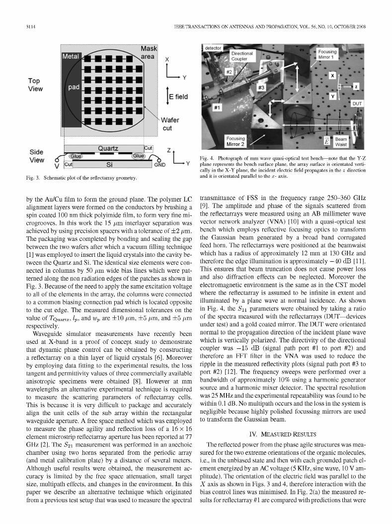
Fig. 4. Photograph of mm wave quasi-optical test bench—note that the Y-Z plane represents the bench surface plane, the array surface is orientated vertically in the X-Y plane, the incident electric field propagates in the z direction and it is orientated parallel to the x- axis.
transmittance of FSS in the frequency range 250-360 GHz [9]. The amplitude and phase of the signals scattered from the reflectarrays were measured using an AB millimeter wave vector network analyzer (VNA) [10] with a quasi-optical test bench which employs reflective focusing optics to transform the Gaussian beam generated by a broad band corrugated feed horn. The reflectarrays were positioned at the beamwaist which has a radius of approximately 12 mm at 130 GHz and therefore the edge illumination is approximately -40 dB [11]. This ensures that beam truncation does not cause power loss and also diffraction effects can be neglected. Moreover the electromagnetic environment is the same as in the CST model where the reflectarray is assumed to be infinite in extent and illuminated by a plane wave at normal incidence. As shown in Fig. 4, the Sn parameters were obtained by taking a ratio of the spectra measured with the reflectarrays (DUT—devices under test) and a gold coated mirror. The DUT were orientated normal to the propagation direction of the incident plane wave which is vertically polarized. The directivity of the directional coupler was —15 dB (signal path port #1 to port #2) and therefore an FFT filter in the VNA was used to reduce the ripple in the measured reflectivity plots (signal path port #3 to port #2) [12]. The frequency sweeps were performed over a bandwidth of approximately 10% using a harmonic generator source and a harmonic mixer detector. The spectral resolution was 25 MHz and the experimental repeatability was found to be within 0.1 dB. No multipath occurs and the loss in the system is negligible because highly polished focussing mirrors are used to transform the Gaussian beam.
IV. MEASURED RESULTS
The reflected power from the phase agile structures was measured for the two extreme orientations of the organic molecules, i.e., in the unbiased state and then with each grounded patch element energized by an AC voltage (5 KHz, sine wave, 10 V amplitude). The orientation of the electric field was parallel to the X axis as shown in Figs. 3 and 4, therefore interaction with the bias control lines was minimised. In Fig. 2(a) the measured results for reflectarray #1 are compared with predictions that were
HU et al.\ DESIGN AND MEASUREMENT OF RECONFIGURABLE MILLIMETER WAVE REFLECTARRAY CELLS 3115
generated by CST over the band 95-110 GHz. It is shown that the resonant frequency decreases from 104.7 GHz (0 V) to 98.2 GHz (10 V) thus permitting discrete phase states to be selected over a 165° range at 102.3 GHz. The measured reflection loss was shown to vary between 4.5 and 6.4 dB within the range of the phase states, thus the figure of merit value is 26°/dB. Very good agreement is shown between the numerical and experimental phase and amplitude results. This is also the case shown in Fig. 2(b) for reflectarray #2. For this structure the measured resonant frequency shifts downwards from 135 to 124.8 GHz when the array is biased thus giving a tunable frequency range of 7.5%. At the center operating frequency of 130.2 GHz the dynamic phase range is approximately 130° and the measured reflection loss varies between 4.3 dB (0 V) and 7 dB (10 V), which is about 2 dB higher than the predicted values. This can probably be attributed to a small deviation in the angle of the sample holder which was found to occur when the calibration mirror was replaced by the reflectarray. The path length between the corrugated feed and the reflectarray is approximately 45 cm, therefore a small angular error will cause a considerable amount of power to be reflected outside the view of the detector horn. On the other hand the phase agility measurements were obtained with and without the bias voltage applied to the reflectarray, and thus because this is a relative measurement, the results are less sensitive to mechanical misalignment.
10 12 14 16 18 20 22 24 26 28 30 32
TLC (*im)
Fig. 5. Computed plots for reflectarray with patch dimensions Dx = Dy = 0.7 mm, lp = 0.6 mm, wp = 0.5 mm and variable superstate and LC layer thickness (a) reflection phase shift, (b) reflection loss and (c) figure of merit.
TABLE I Loss FACTORS AND MEASURED TOTAL Loss
Reflectarray
l#(102GHz)
2# (132 GHz)
Loss in LC
4.4 dB 3.2 dB
Loss in Copper
2.4 dB 1.5 dB
Loss in Quartz
0.1 dB 0.1 dB
Total loss
CST Mea. 6.9 dB 6.4dB 4.8dB 7dB
V. DISCUSSION, APPLICATIONS AND CONCLUSION
The computed plane wave scattering from two reflectarray structures with tunable liquid crystal substrate was shown to be in good agreement with experimental results which were obtained from a reflective focussing optics test bench. This is the first time that a quasi-optical technique has been used to measure the dynamic response of a phase agile reflectarray at mm wavelengths. In addition to overcoming the drawbacks of a simple free space measurement system, the quasi-optical method creates an electromagnetic environment which is identical to the one used in the computer model, and moreover the results can be used to yield the dielectric properties of the LC specimens [1]. Table I summarizes the maximum loss components obtained from the simulations using CST at the center operating frequency of the two reflectarray s which have a LC thickness of 15 /im. It is noted that both the LC absorption loss and the Ohmic loss are lower when the substrate is electrically thicker. Similarly in Fig. 2(a) and (b), the phase agility of the structure is also shown to decrease around resonance because in this region the phase slope versus frequency is inversely proportional to the substrate thickness [13], [14]. The tradeoff between signal loss and the dynamic phase range for different superstate and LC layer thicknesses is depicted in Fig. 5 where the maximum figure of merit is shown to be around 30°/dB. A significant reduction in the loss could be obtained by increasing the thickness of the tunable LC substrate as shown in Fig. 5, however an increase in the figure of merit would require the synthesis of a LC mixture which has a lower loss tangent and a larger anisotropy value than BL037 [4]. Moreover in order to homogeneously align the LC molecules in the unbias state, and hence maximize Aeeff, a thin tunable layer which is typically less than 500 /im [7], must be used. This therefore imposes a lower frequency limitation on
the operation of this type of resonant antenna structure because as observed in Table I the Ohmic loss increases significantly when the electrical spacing between the periodic array and the ground plane is reduced. Further evidence of this, which can be attributed to the higher field intensity in the substrate, is shown in [13, Fig. 6], [14] and [15].
The phase characterization of passive reflectarray elements has recently been demonstrated at 28.3 THz [16] using advanced design, fabrication and interferometer measurement techniques. This technique could be developed further to exploit the anisotropy property of liquid crystals in order to provide phase agile devices for emerging applications at infrared.
In the mm and sub mm wave bands an important application for the LC reflectarray technology is in the spaceborne meteorological and atmospheric chemistry sounding instruments [17]. A phase agile reflectarray based on liquid crystal substrate offers a viable alternative to current technology which employs motor driven systems to physically steer the antennas. With future mission lifetimes of up to 10 years, tribology issues with mechanically scanned antenna systems can therefore be eliminated. Limbsounder instruments view the Earth scene by scanning the high gain reflector antenna though a small angle which is generally less than 5° [17]. This type of scan profile can be achieved by applying the appropriate signals to the bias lines which connect all of the patches in the individual columns in order to produce the required progressive phase on the reflected field [2], [3]. Moreover in addition to this simple biasing arrangement, the fabrication of the phase agile structure can be made easier by employing a planar reflectarray subreflector in a Cassegrain dual-reflector antenna [18]. This design option is very attractive for passive remote sensing instruments because it combines the high gain and broad bandwidth properties of the
3116 IEEE TRANSACTIONS ON ANTENNAS AND PROPAGATION, VOL. 56, NO. 10, OCTOBER 2008
parabolic main reflector with the simplicity of manufacturing a small electronically reconfigurable reflectarray which can be located in the thermally controlled quasi-optical feed train of the instrument [19].
REFERENCES
[1] W. Hu, R. Dickie, R. Cahill, H. S. Gamble, M. Y. Ismail, V. F. Fusco, D. Linton, S. P. Rea, and N. Grant, "Liquid crystal tunable mm wave frequency selective surface," IEEE Microw. Wireless Compon. Lett., vol. 17, no. 9, pp. 667-669, Sep. 2007.
[2] R. Moessinger, J. Marin, S. Freese, S. Mueller, A. Manabe, and R. Jakoby, "77 GHz reconfigurable reflectarray with nematic liquid crystal," in Proc. Eur. Conf. on Antennas Propag., Edinburgh, UK, Oct. 2007.
[3] W. Hu, M. Y. Ismail, R. Cahill, J. A. Encinar, R. Dickie, H. S. Gamble, V. F. Fusco, D. Linton, S. P. Rea, and N. Grant, "Liquid crystal based reflectarray antenna with electronically switchable monopulse patterns," Electron. Lett., vol. 43, no. 14, pp. 744-745, 2007.
[4] A. Penirschke, S. Muller, P. Scheele, C. Weil, M. Wittek, C. Hock, and R. Jacoby, "Cavity perturbation method for characterization of liquid crystals up to 35 GHz," in 34th Eur. Microw. Conf., Amsterdam, 2004, pp. 545-548.
[5] [Online]. Available: http://www.liquidcrystals.merck.de [6] W. Hu, M. Y. Ismail, R. Cahill, H. S. Gamble, R. Dickie, V. F. Fusco,
D. Linton, S. P. Rea, and N. Grant, "Tunable liquid crystal reflectarray patch element," Electron. Lett., vol. 42, no. 9, pp. 15-16, 2006.
[7] W. Hu, M. Y. Ismail, R. Cahill, R. Dickie, H. S. Gamble, V. F. Fusco, D. Linton, S. P. Rea, and N. Grant, "Phase control of reflectarray patches using liquid crystal substrate," in Proc. Eur. Conf. on Antennas Propag., Nice, France, Nov. 2006.
[8] M. Y. Ismail, W. Hu, R. Cahill, V. F. Fusco, H. S. Gamble, D. Linton, R. Dickie, S. P. Rea, and N. Grant, "Phase agile reflectarray cells based on liquid crystals," Proc IETMicrow. Antennas Propag., vol. 1, no. 4, pp. 809-814, 2007.
[9] R. Dickie, R. Cahill, H. S. Gamble, V. F. Fusco, A. Schuchinsky, and N. Grant, "Spatial demultiplexing in the sub-mm wave band using multilayer free-standing frequency selective surfaces," IEEE Trans. Antennas Propag., vol. 53, no. 6, pp. 1904-1911, 2005.
[10] [Online]. Available: http://www.abmillimetre.com [11] P. F. Goldsmith, "Quasi-optical techniques offer advantages at mil
limeter frequencies," Microw. Syst. News, pp. 65-84, Dec. 1983. [12] P. Goy and M. Gross, "Free space vector transmission-reflection
from 18 GHz to 760 GHz," presented at the 24th Eur. Microw. Conf., Cannes, France, Oct. 4-6, 1994.
[13] D. M. Pozar, S. D. Targonski, andH. D. Syrigos, "'Design of millimeter wave microstrip reflectarrays," IEEE Trans. Antennas Propag., vol. 45, no. 2, pp. 287-295, 1997.
[14] J. Huang and J. A. Encinar, Reflectarray antennas. Piscataway, NJ: Wiley-IEEE Press, 2007.
[15] M. Y. Ismail, W. Hu, R. Cahill, H. S. Gamble, R. Dickie, V. F. Fusco, D. Linton, and S. P. G. ReaN, "Performance of reflectarray cells printed on liquid crystal film," presented at the IEEE Asia Pacific Conf. on Electromagn. (APMC-2006), Yokohama, Japan, Dec. 12-15, 2006.
[16] J. C. Ginn, B. A. Lail, and G. D. Boreman, "Phase characterization of reflectarray elements at infrared," IEEE Trans. Antennas Propag., vol. 55, no. 11, pp. 2989-2993, 2007.
[17] M. Oldfield et al, "MARSCHALS: Development of an airborne millimetre-wave limb sounder," in Proc. 8th Int. Symp. on Remote Sensing, SPIE4540, 2001, pp. 221-228.
[18] M. Arrebola, L. d. Haro, and J. A. Encinar, "Analysis of a cassegrain antenna with a reflectarray as subreflector," in Proc. 29th ESA Antenna Workshop on Multiple Beams and Reconfigurable Antennas Innovation and Challenges, Noordwijk, The Netherlands, Apr. 2007, pp. 18-20.
[19] M. Arrebola, W. Hu, J. A. Encinar, R. Cahill, V. F. Fusco, H. S. Gamble, and N. Grant, "94 GHz beam scanning dual-reflector antenna with sub-reflectarray," presented at the 30th ESA Antenna Workshop on Antennas for Earth Observation, Science Telecommunication and Navigation Space Missions, Innovation and Challenges, Noordwijk, The Netherlands, May 30, 2008.
Wenfei Hu (M'03) received the B.Sc. degree in physics from the University of Qufu, Qufu, China, in 1993, the M.Eng. degree in optoelectronics from the University of Shandong, Shandong, China, in 1998,
Iand the Ph.D. degree from the Institute of Physics,
Chinese Academy of Sciences, Beijing, China, in 2001. His doctoral research was on thin film electronics in ferroelectric/superconducting multilayer structures for tuneable microwave applications.
From 2001 to 2005, he was a Research Assistant in the Emerging Device Technology Research Centre,
Birmingham University, Birmingham, U.K., where he worked on thin- and thick-film ferroelectric microwave devices including filters and phase shifters for S- and K-band applications. Upon leaving Birmingham University, he joined the High Frequency Electronics (HFE) Group, Institute of Electronics, Communication and Information Technology (ECIT), Queen's University Belfast, Belfast, Ireland, as a Research Fellow. His research concerns novel integral electronic beam scanning reflectarray antennas based on liquid-crystal material. He is currently working on micromachined electronic beam-scanning antenna array systems for millimeter and submillimeter applications. He is also actively involved in the development of novel material technology for the phase control of microwave circuits. His research interests include the design, microfabrication, packaging and measurement of monolithic integrated reconfigurable mm wave and terahertz array antennas for communication and sensing/imaging applications.
Robert Cahill received the B.Sc. degree (with first class honors) in physics from the University of Aston, Birmingham, U.K., in 1979 and the Ph.D. degree in microwave electronics from the University of Kent at Canterbury, U.K., in 1982.
He joined Queen's University Belfast (QUB), Belfast, Northern Ireland, in 1999 after a 17 year ca-
^^4L ^ ^ ^ ^ h reer working in the U.K. space and defense industry, ^ k gf I where he worked on antenna and passive microwave
i I I * device technology projects. During this time, he pioneered methods for predicting the performance
of antennas on complex scattering surfaces such as satellites and has developed techniques for analyzing and fabricating millimeter and submillimeter wave quasi-optical dichroic filters. Recently, he has established a 100-600 GHz quasi-optical S parameter measurement facility at QUB. He has exploited the results of numerous research projects, sponsored by the European Space Agency, EADS Astrium Space Ltd., the British National Space Agency, and the U.K. Meteorological Office, to develop quasi-optical demultiplexers for atmospheric sounding radiometers in the range 89-500 GHz. These include AMSU-B, AMAS, MARSCHALS, and the ESA 500 GHz demonstrator. His recent interests also include the characterization of liquid crystal materials at microwave and mm wavelengths, and strategies for broad banding and creating active reflectarray antennas. He has authored and coauthored over 100 publications and holds four international patents.
Jose A. Encinar (S'81-M'86) was born in Madrid, Spain. He received the Electrical Engineer and Ph.D. degrees from the Universidad Politecnica de Madrid (UPM), in 1979 and 1985, respectively.
Since January 1980 has been with the Applied Electromagnetism and Microwaves Group at UPM, as a Teaching and Research Assistant from 1980 to 1982, as an Assistant Professor from 1983 to 1986, and as Associate Professor from 1986 to 1991. From February to October of 1987, he stayed at Polytechnic University, Brooklyn, NY, as a Post
doctoral Fellow of the NATO Science Program. Since 1991 he has been a Professor of the Electromagnetism and Circuit Theory Department, UPM. In 1996, he was a Visiting Professor with the Laboratory of Electromagnetics and Acoustics, Ecole Polytechnique Federale de Lausanne, Switzerland, and in 2006 with the Institute of Electronics, Communication and Information Technology (ECIT), Queen's University Belfast, Ireland. His research interests include numerical techniques for the analysis of multilayer periodic structures, design of frequency-selective surfaces, printed arrays, and reflectarrays. He has published more than 100 journal and conference papers, and he is holder of three patents on array and reflectarray antennas.
Dr. Encinar was a co-recipient of the 2005 H. A. Wheeler Applications Prize Paper Award and the 2007 S. A. Schelkunoff Transactions Prize Paper Award, given by IEEE Antennas Propagation Society.
HU et al: DESIGN AND MEASUREMENT OF RECONFIGURABLE MILLIMETER WAVE REFLECTARRAY CELLS 3117
c> Raymond Dickie received the B.Eng. degree (with honors) and the Ph.D. degree in electrical and electronic engineering from The Queens University of Belfast (QUB), Belfast, Ireland, in 2001 and 2004, respectively.
Since October 2004, he has worked as a Postdoctoral Research Fellow in the High Frequency Electronic Circuits and Antennas Group, the Institute of Electronics, Communications, and Information Technology (ECIT), QUB. His research interests include micromachining techniques for fabricating high as
pect ratio 3-D structures from thick photoresist, RIE of polymers, thin film metal deposition, and high conductivity stress controlled electroplating, electromagnetic modeling of FSS and precision quasi-optical measurements in the millimeter and submillimeter wave bands.
^ ^ ^ ^ Harold S. Gamble received the B.Sc. degree (first class honors) in electrical and electronic engineering and the Ph.D. degree from The Queens University of Belfast (QUB), Belfast, Ireland, in 1966 and 1969, respectively.
As a Research Engineer at The Standard Telecommunication Laboratories, Harlow Essex, U.K., he established a polysilicon gate process for MOS integrated circuits. He was appointed to a lectureship at QUB in 1973 and has lead research there in silicon device design and related technology
including, CCDs, silicided shallow junctions, rapid thermal CVD, GTOs, and static induction thyristors. In 1992, he was promoted to Professor of Microelectronic Engineering and is at present Director of the Northern Ireland Semiconductor Research Centre. Major activity at present is the use of direct silicon wafer bonding for producing silicon-on-insulator (SOI) substrates for lowpower bipolar transistor circuits. This includes trench and refill before bond technology and buried metallic layers to eliminate epitaxial layers and to minimize collector resistance. Ground plane SOI structures incorporating tungsten silicide layers are being investigated for cross talk suppression in mixed signal circuits and for ultra short MOSTs. The silicon wafer bonding combined with the integrated circuit patterning techniques is also being applied to micro-machining applications such as sensors, mechanical actuators and 3-D mm wave components. Other projects include multilayer free-standing frequency selective surfaces for spatial demultiplexing in the submillimeter wave band, thin film transistors in polysilicon or bonded silicon on glass for displays/imagers, and high density interconnects produced by sputtering and CVD for ICs and MR heads. He has coauthored over 250 publications in the area of silicon devices and thin film technology.
s Pi
Vincent Fusco (S'82-M'82-SM'96-F'04) received the Bachelors degree in electrical and electronic engineering (first class honors), the Ph.D. degree in microwave electronics, and the D.Sc. degree for his work on advanced front end architectures with enhanced functionality, from The Queens University of Belfast (QUB), Belfast, Ireland, in 1979, 1982, and 2000, respectively.
Since 1995, he has held a Personal Chair in High Frequency Electronic Engineering, QUB, and is the Director of the EU funded Microwave and Millimeter
Wave Resource Center. From 2002 to 2003, he was appointed Visiting Full Professor at the University of Nice at Sophia-Antipolis. At present, he is Technical Director of the High Frequency Laboratories, Institute of Electronics, Communications, and Information Technology (ECIT), QUB, he is also Director of the International Centre for Research for System on Chip and Advanced Mi-crowireless Integration (SoCaM). He holds several patents and has contributed invited chapters to several books in the field of active antenna design and EM field computation. He has pioneered many new concepts in self-tracking antenna technology. He has published over 420 scientific papers in major journals and international conferences, and is the author of two text books. He holds several patents on active and retrodirective antennas and has contributed invited chapters to books in the fields of active antenna design and EM field computation. His research interests include nonlinear microwave circuit design, and active and passive antenna techniques.
Prof. Fusco is a Fellow of the Royal Academy of Engineering and the Institution of Engineering and Technology (IET), London, U.K., since 1996. In 1986, he was awarded a British Telecommunications Fellowship and in 1997 he was awarded the NI Engineering Federation Trophy for outstanding industrially relevant research
Norman Grant received the Ph.D. degree from Pacific Western University, Los Angeles, CA, in 1989 for the development of a 200 GHz subharmonicaily pumped mixer.
He has had 25 years experience working on metrological sounder and atmospheric chemistry programmes and was responsible for the development of the front-end receiver technology for
^^L ^ ^ AMSU-B with Matra Marconi Space at Portsmouth si-i&l ^Htk i ^ S a England. He subsequently moved to British
Aerospace Space Systems as the Executive in charge of millimeter-wave business development and technology. He was also responsible for obtaining the Humidity Sounder Brazil development contract for British Aerospace Space Systems. He is currently with The Directorate of Earth Observation and Science, EADS/ASTRIUM Limited, Portsmouth, Hampshire, U.K. Recently he has been working on the conceptual design and development of a new generation of microwave space science instruments which operate between 23-900 GHz.
Dr. Grant is a Chartered Engineer and is a Fellow of the Institution of Engineering and Technology (IET), London, U.K.