Design and operation of a Tesla-type valve for pulsating heat pipes de Vries, S.F.; Florea, D.; Homburg, F.G.A.; Frijns, A.J.H. Published in: International Journal of Heat and Mass Transfer DOI: 10.1016/j.ijheatmasstransfer.2016.09.062 Published: 01/02/2017 Document Version Publisher’s PDF, also known as Version of Record (includes final page, issue and volume numbers) Please check the document version of this publication: • A submitted manuscript is the author's version of the article upon submission and before peer-review. There can be important differences between the submitted version and the official published version of record. People interested in the research are advised to contact the author for the final version of the publication, or visit the DOI to the publisher's website. • The final author version and the galley proof are versions of the publication after peer review. • The final published version features the final layout of the paper including the volume, issue and page numbers. Link to publication Citation for published version (APA): de Vries, S. F., Florea, D., Homburg, F. G. A., & Frijns, A. J. H. (2017). Design and operation of a Tesla-type valve for pulsating heat pipes. International Journal of Heat and Mass Transfer, 105, 1-11. DOI: 10.1016/j.ijheatmasstransfer.2016.09.062 General rights Copyright and moral rights for the publications made accessible in the public portal are retained by the authors and/or other copyright owners and it is a condition of accessing publications that users recognise and abide by the legal requirements associated with these rights. • Users may download and print one copy of any publication from the public portal for the purpose of private study or research. • You may not further distribute the material or use it for any profit-making activity or commercial gain • You may freely distribute the URL identifying the publication in the public portal ? Take down policy If you believe that this document breaches copyright please contact us providing details, and we will remove access to the work immediately and investigate your claim. Download date: 20. Jan. 2019
Transcript
Design and operation of a Tesla-type valve for pulsatingheat pipesde Vries, S.F.; Florea, D.; Homburg, F.G.A.; Frijns, A.J.H.
Published in:International Journal of Heat and Mass Transfer
DOI:10.1016/j.ijheatmasstransfer.2016.09.062
Published: 01/02/2017
Document VersionPublisher’s PDF, also known as Version of Record (includes final page, issue and volume numbers)
Please check the document version of this publication:
• A submitted manuscript is the author's version of the article upon submission and before peer-review. There can be important differencesbetween the submitted version and the official published version of record. People interested in the research are advised to contact theauthor for the final version of the publication, or visit the DOI to the publisher's website.• The final author version and the galley proof are versions of the publication after peer review.• The final published version features the final layout of the paper including the volume, issue and page numbers.
Link to publication
Citation for published version (APA):de Vries, S. F., Florea, D., Homburg, F. G. A., & Frijns, A. J. H. (2017). Design and operation of a Tesla-typevalve for pulsating heat pipes. International Journal of Heat and Mass Transfer, 105, 1-11. DOI:10.1016/j.ijheatmasstransfer.2016.09.062
General rightsCopyright and moral rights for the publications made accessible in the public portal are retained by the authors and/or other copyright ownersand it is a condition of accessing publications that users recognise and abide by the legal requirements associated with these rights.
• Users may download and print one copy of any publication from the public portal for the purpose of private study or research. • You may not further distribute the material or use it for any profit-making activity or commercial gain • You may freely distribute the URL identifying the publication in the public portal ?
Take down policyIf you believe that this document breaches copyright please contact us providing details, and we will remove access to the work immediatelyand investigate your claim.
International Journal of Heat and Mass Transfer 105 (2017) 1–11
Contents lists available at ScienceDirect
International Journal of Heat and Mass Transfer
journal homepage: www.elsevier .com/locate / i jhmt
Design and operation of a Tesla-type valve for pulsating heat pipes
http://dx.doi.org/10.1016/j.ijheatmasstransfer.2016.09.0620017-9310/� 2016 The Authors. Published by Elsevier Ltd.This is an open access article under the CC BY license (http://creativecommons.org/licenses/by/4.0/).
S.F. de Vries, D. Florea, F.G.A. Homburg, A.J.H. Frijns ⇑Department of Mechanical Engineering, Eindhoven University of Technology, Eindhoven, The Netherlands
a r t i c l e i n f o a b s t r a c t
Article history:Received 15 April 2016Received in revised form 10 August 2016Accepted 19 September 2016
A new Tesla-type valve is successfully designed for promoting circulation in a pulsating heat pipe (PHP)and improving the thermal resistance. Its functionality and diodicity is tested by laminar single-phasemodelling and by steady two-phase flow experiments. The valve is symmetrically integrated in asingle-turn PHP, which reduces variabilities to give a more thorough understanding of the behaviourin PHPs. Two transparent bottom-heated PHPs, one with and one without valves, are manufacturedand the flow behaviour and thermal performance is studied. The valves produced a diodicity which leadto a difference in velocity of 25% for the different flow directions. Furthermore, a decrease of 14% in ther-mal resistance was observed due to the addition of the valves.� 2016 The Authors. Published by Elsevier Ltd. This is an openaccess article under the CCBY license (http://
creativecommons.org/licenses/by/4.0/).
1. Introduction
The demand for faster and smaller micro-electronic systemscontinues to increase and consequently, the amount of producedheat per volume increases. Therefore, the need for novel efficientcooling devices is vast [1]. Heat pipes are effective passive heatspreaders that can be used to solve this problem. Due to the com-bined convection and phase transition, a high heat exchanging effi-ciency can be achieved [2]. A drawback of the traditional heat pipeis that it requires an intricate wick structure and cannot be easilyminiaturised due to the capillary limit [3]. Therefore, a new heatpipe called the Pulsating (or Oscillating) Heat Pipe (PHP) was intro-duced by Akachi in 1990 [4]. The main benefits of the PHP are thatit has a very simple shape with no wick structure, which can beeasily miniaturised. This makes it a very inexpensive and easy-to-integrate heat spreader which can be beneficial for many, alsonon-electronic, applications [5].
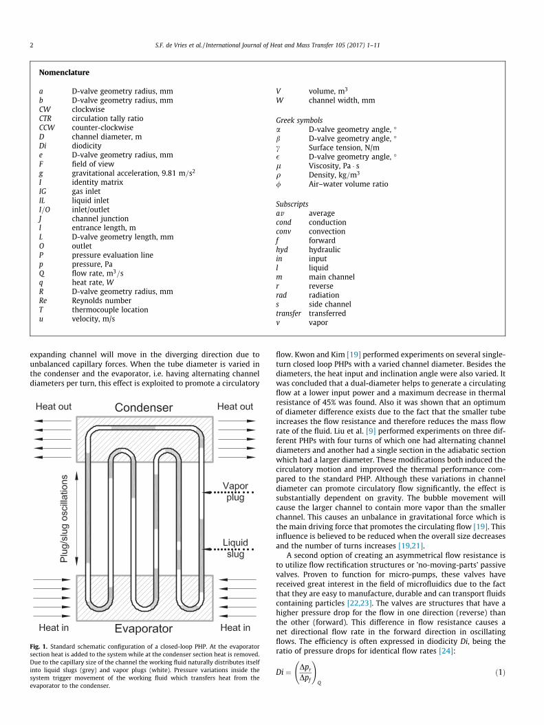
A PHP generally consists of a simple meandering capillary tubeor channel which alternatingly passes through evaporator (heat-ing) and condenser (cooling) zones as schematically shown inFig. 1. Due to the capillary size of the channel a series of liquidslugs and vapor plugs is formed by the working fluid. The constantheat exchange triggers phase-change phenomena which result inpressure variations inside the device that consequently triggermovement of the liquid slugs and plugs. The overall heat transferis mainly determined by the sensible heat transfer and the latentheat contributes mostly to the movement of the slugs and plugs
[6]. The performance of a PHP thus relies on the continuous non-equilibrium conditions throughout the system and an intricateinterplay of physical phenomena. Depending on the specific condi-tions, the liquid slugs are stagnant, pulsating, circulating with asuperimposed pulsation or purely circulating [7,8]. Furthermore,the flow pattern can vary from the normal bubble–liquid slug flowto annular flow [9]. The PHP has received large interest in thescientific community, however, due to the complexity and chaoticbehaviour, no fully comprehensive theory or model and no generaldesign tools are available [10,11].
It is known that circulation of the working fluid contributes to abetter performance of the PHP [12–14]. The liquid contact in theevaporator is increased when the working fluid is circulating,which increases the heat transfer. This makes it interesting toinvestigate methods to promote circulatory motion in a PHP[9,15]. Moreover, directional promotion could increase the stabilityand predictability of the PHP.
Circulatory motion has been induced inside PHPs using asym-metrical heating [16], floating-ball check valves [17], a variationof channel diameters [9,18,19] and Tesla-type valves [20].Although being of scientific interest, promoting the circulationusing asymmetrical heating is not practically applicable. Similarly,using floating-ball check valves inherently contradicts the benefitsof the PHP by having a moving part and being difficult to manufac-ture when integrated and/or miniaturised.
A more practical solution is to utilize asymmetrical flow resis-tance to promote directional circulation. Holley and Faghri [18]were the first to suggest this by varying the channel diameter. Itwas demonstrated that this could theoretically improve a direc-tional flow in a single-turn PHP and also improve the heat transfer.These phenomena were attributed to the fact that a bubble in an
Subscriptsav averagecond conductionconv convectionf forwardhyd hydraulicin inputl liquidm main channelr reverserad radiations side channeltransfer transferredv vapor
2 S.F. de Vries et al. / International Journal of Heat and Mass Transfer 105 (2017) 1–11
expanding channel will move in the diverging direction due tounbalanced capillary forces. When the tube diameter is varied inthe condenser and the evaporator, i.e. having alternating channeldiameters per turn, this effect is exploited to promote a circulatory
Fig. 1. Standard schematic configuration of a closed-loop PHP. At the evaporatorsection heat is added to the system while at the condenser section heat is removed.Due to the capillary size of the channel the working fluid naturally distributes itselfinto liquid slugs (grey) and vapor plugs (white). Pressure variations inside thesystem trigger movement of the working fluid which transfers heat from theevaporator to the condenser.
flow. Kwon and Kim [19] performed experiments on several single-turn closed loop PHPs with a varied channel diameter. Besides thediameters, the heat input and inclination angle were also varied. Itwas concluded that a dual-diameter helps to generate a circulatingflow at a lower input power and a maximum decrease in thermalresistance of 45% was found. Also it was shown that an optimumof diameter difference exists due to the fact that the smaller tubeincreases the flow resistance and therefore reduces the mass flowrate of the fluid. Liu et al. [9] performed experiments on three dif-ferent PHPs with four turns of which one had alternating channeldiameters and another had a single section in the adiabatic sectionwhich had a larger diameter. These modifications both induced thecirculatory motion and improved the thermal performance com-pared to the standard PHP. Although these variations in channeldiameter can promote circulatory flow significantly, the effect issubstantially dependent on gravity. The bubble movement willcause the larger channel to contain more vapor than the smallerchannel. This causes an unbalance in gravitational force which isthe main driving force that promotes the circulating flow [19]. Thisinfluence is believed to be reduced when the overall size decreasesand the number of turns increases [19,21].
A second option of creating an asymmetrical flow resistance isto utilize flow rectification structures or ’no-moving-parts’ passivevalves. Proven to function for micro-pumps, these valves havereceived great interest in the field of microfluidics due to the factthat they are easy to manufacture, durable and can transport fluidscontaining particles [22,23]. The valves are structures that have ahigher pressure drop for the flow in one direction (reverse) thanthe other (forward). This difference in flow resistance causes anet directional flow rate in the forward direction in oscillatingflows. The efficiency is often expressed in diodicity Di, being theratio of pressure drops for identical flow rates [24]:
Di ¼ Dpr
Dpf
!Q
ð1Þ
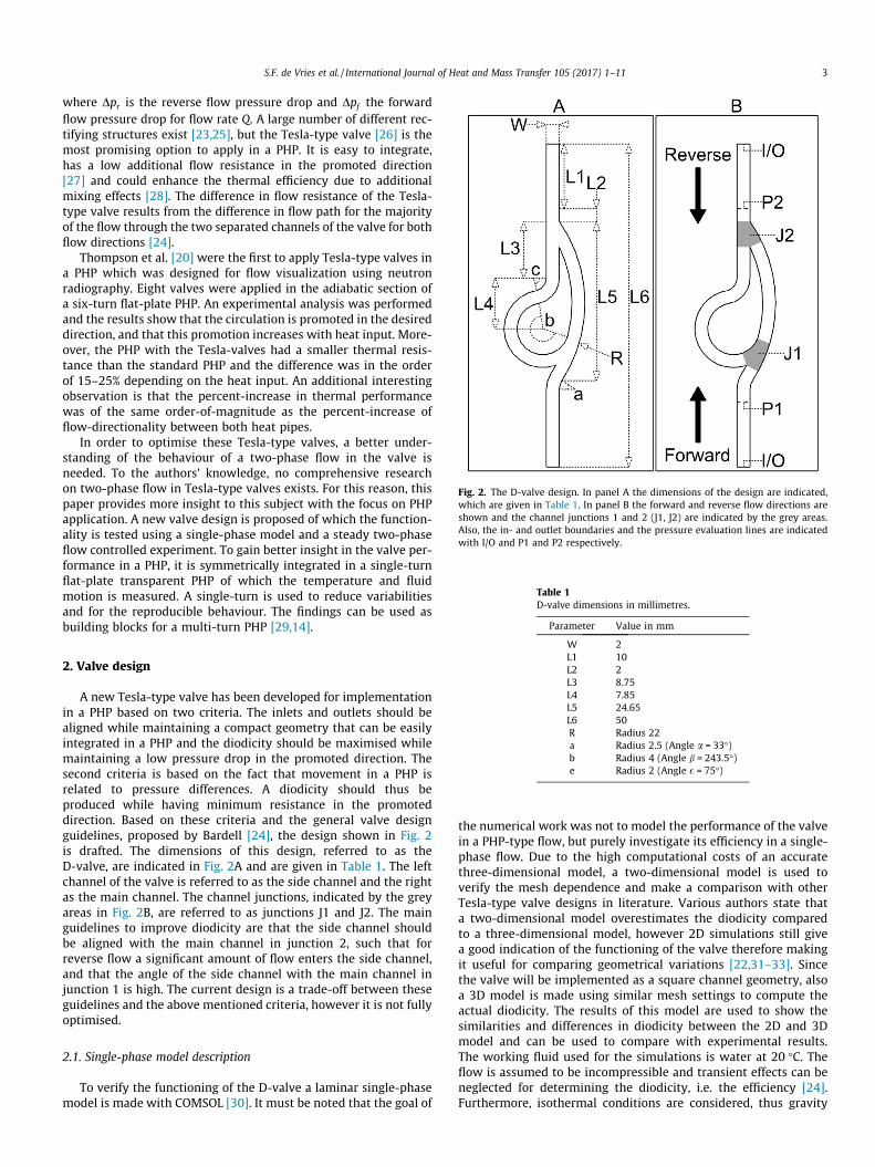
Fig. 2. The D-valve design. In panel A the dimensions of the design are indicated,which are given in Table 1. In panel B the forward and reverse flow directions areshown and the channel junctions 1 and 2 (J1, J2) are indicated by the grey areas.Also, the in- and outlet boundaries and the pressure evaluation lines are indicatedwith I/O and P1 and P2 respectively.
Table 1D-valve dimensions in millimetres.
Parameter Value in mm
S.F. de Vries et al. / International Journal of Heat and Mass Transfer 105 (2017) 1–11 3
where Dpr is the reverse flow pressure drop and Dpf the forwardflow pressure drop for flow rate Q. A large number of different rec-tifying structures exist [23,25], but the Tesla-type valve [26] is themost promising option to apply in a PHP. It is easy to integrate,has a low additional flow resistance in the promoted direction[27] and could enhance the thermal efficiency due to additionalmixing effects [28]. The difference in flow resistance of the Tesla-type valve results from the difference in flow path for the majorityof the flow through the two separated channels of the valve for bothflow directions [24].
Thompson et al. [20] were the first to apply Tesla-type valves ina PHP which was designed for flow visualization using neutronradiography. Eight valves were applied in the adiabatic section ofa six-turn flat-plate PHP. An experimental analysis was performedand the results show that the circulation is promoted in the desireddirection, and that this promotion increases with heat input. More-over, the PHP with the Tesla-valves had a smaller thermal resis-tance than the standard PHP and the difference was in the orderof 15–25% depending on the heat input. An additional interestingobservation is that the percent-increase in thermal performancewas of the same order-of-magnitude as the percent-increase offlow-directionality between both heat pipes.
In order to optimise these Tesla-type valves, a better under-standing of the behaviour of a two-phase flow in the valve isneeded. To the authors’ knowledge, no comprehensive researchon two-phase flow in Tesla-type valves exists. For this reason, thispaper provides more insight to this subject with the focus on PHPapplication. A new valve design is proposed of which the function-ality is tested using a single-phase model and a steady two-phaseflow controlled experiment. To gain better insight in the valve per-formance in a PHP, it is symmetrically integrated in a single-turnflat-plate transparent PHP of which the temperature and fluidmotion is measured. A single-turn is used to reduce variabilitiesand for the reproducible behaviour. The findings can be used asbuilding blocks for a multi-turn PHP [29,14].
W 2L1 10L2 2L3 8.75L4 7.85L5 24.65L6 50R Radius 22a Radius 2.5 (Angle a = 33�)b Radius 4 (Angle b = 243.5�)e Radius 2 (Angle � = 75�)
2. Valve design
A new Tesla-type valve has been developed for implementationin a PHP based on two criteria. The inlets and outlets should bealigned while maintaining a compact geometry that can be easilyintegrated in a PHP and the diodicity should be maximised whilemaintaining a low pressure drop in the promoted direction. Thesecond criteria is based on the fact that movement in a PHP isrelated to pressure differences. A diodicity should thus beproduced while having minimum resistance in the promoteddirection. Based on these criteria and the general valve designguidelines, proposed by Bardell [24], the design shown in Fig. 2is drafted. The dimensions of this design, referred to as theD-valve, are indicated in Fig. 2A and are given in Table 1. The leftchannel of the valve is referred to as the side channel and the rightas the main channel. The channel junctions, indicated by the greyareas in Fig. 2B, are referred to as junctions J1 and J2. The mainguidelines to improve diodicity are that the side channel shouldbe aligned with the main channel in junction 2, such that forreverse flow a significant amount of flow enters the side channel,and that the angle of the side channel with the main channel injunction 1 is high. The current design is a trade-off between theseguidelines and the above mentioned criteria, however it is not fullyoptimised.
2.1. Single-phase model description
To verify the functioning of the D-valve a laminar single-phasemodel is made with COMSOL [30]. It must be noted that the goal of
the numerical work was not to model the performance of the valvein a PHP-type flow, but purely investigate its efficiency in a single-phase flow. Due to the high computational costs of an accuratethree-dimensional model, a two-dimensional model is used toverify the mesh dependence and make a comparison with otherTesla-type valve designs in literature. Various authors state thata two-dimensional model overestimates the diodicity comparedto a three-dimensional model, however 2D simulations still givea good indication of the functioning of the valve therefore makingit useful for comparing geometrical variations [22,31–33]. Sincethe valve will be implemented as a square channel geometry, alsoa 3D model is made using similar mesh settings to compute theactual diodicity. The results of this model are used to show thesimilarities and differences in diodicity between the 2D and 3Dmodel and can be used to compare with experimental results.The working fluid used for the simulations is water at 20 �C. Theflow is assumed to be incompressible and transient effects can beneglected for determining the diodicity, i.e. the efficiency [24].Furthermore, isothermal conditions are considered, thus gravity
Fig. 3. Grey-scale surface plot of velocity magnitude in forward flow right andreverse flow left, computed with the 2D-model. Uniformly positioned streamlinesand the velocity field on four lines, indicated by arrows, are also plotted. The grey-scale range and arrows are proportional for both directions. Furthermore, thepressures differences generated between the evaluation lines are indicated. Theaverage inlet velocity is 0.1 m/s corresponding to Re = 200.
4 S.F. de Vries et al. / International Journal of Heat and Mass Transfer 105 (2017) 1–11
effects can be disregarded. Therefore, the following Navier–Stokesand continuity equations are solved by the model:
qðu � rÞu ¼ r � ½�pIþ lðruþ ðruÞTÞ� ð2Þ
qr � ðuÞ ¼ 0 ð3ÞThe geometry shown in Fig. 2 is meshed with a free-tetrahedral
mesh with refinement of the mesh where large velocity gradientsare expected, i.e. near channel junctions and the walls. Mesh inde-pendence was verified with the 2D model, using the same criteriaas Gamboa et al. [31], i.e. by doubling the number of elementsstarting with a coarse mesh until the solution changed less than4%. This resulted in a mesh of 44,000 elements for the 2D modeland 1260,000 elements for the 3D model.
A forward and reverse flow case is studied for a range of Rey-nolds numbers. The Reynolds number is defined asRe � qDhydu=l with q the fluid density, Dhyd the hydraulic channeldiameter, u the characteristic fluid velocity and l the fluid viscos-ity. The Re of the liquid slugs in a PHP can be of an order of 102 to103 [29], but Thompson et al. [32] indicate that transitional flowbehaviour can exist in a 3D Tesla-type valve for ReJ300. Themodelled Re range is therefore determined by the convergence ofthe model, i.e. the part where pure laminar flow exists. In forwardflow the bottom boundary is set as the inlet and the top boundaryas the outlet, both indicated with I/O in Fig. 2. This is the other wayaround for reverse flow. At the inlet, a laminar inflow condition isapplied using an entrance length to have a fully developed inletflow [34]:
l ¼ 0:056 � Dhyd � Rein ð4Þwhere Rein is the Reynolds number based on the average inlet velo-city and hydraulic diameter. A zero pressure condition is applied atthe outlet. The other boundaries (solid black lines in Fig. 2) have ano-slip boundary condition. The symmetry of the problem is usedby applying a symmetry and no-slip boundary condition at theadditional symmetry plane and bottom boundary of the 3D modelrespectively. Thus, only a 1 mm deep geometry, corresponding toa hydraulic diameter of 2 mm, has to be solved which saves compu-tation time. For the 2D model a direct PARDISO solver is used andfor the 3D model an iterative GMRES solver. The relative toleranceis 10�3. The pressure drop in each direction is calculated by evalu-ating the average pressure on the evaluation lines/surfaces, indi-cated with P1 and P2 in Fig. 2B. Computing the pressure drop foreach flow direction and dividing these results in the diodicity forthe corresponding Reynolds number.
2.2. Valve characteristics
A surface plot of the velocity magnitude, plotted in grey-scale,obtained by the 2D model in both directions for Re ¼ 200 is shownin Fig. 3. Reverse flow is shown on the left and forward on the right.Furthermore, uniformly positioned streamlines and the velocityfield on four lines, indicated by arrows, are also plotted. As men-tioned, the working principle of a Tesla-type valve is based on a dif-ference in flow distribution between both flow directions, whichresults in a difference in pressure drop for the same inlet flowrate.When the pressure drop would be identical for both directions, thiswill result in a difference in flowrate. As can be seen in Fig. 3, 83%of the flow goes through the main channel in the forward casewhile 55% goes through the main channel in the reverse case. Thisdifference in distribution is dependent on the inertia of the flowand therefore inherently increases with Re. The flow through theside channel has to be redirected downstream, which requires sig-nificant pressure work. When combined with the main channelflow, it also creates a high shear region in junction 2. For the lami-
nar range, these are the main sources of diodicity in a Tesla-typevalve [24].
As shown in Fig. 3, a clear recirculation zone exists in the sidechannel for the forward case resulting in a small separated jet. Thisjet shows to be more pronounced in 3D. The 2D forward case doesnot converge for Re > 650, while the reverse case is still conver-ging. With only the forward case of the 3D model not convergingfor Re > 200, this phenomena is believed to result in transitionalflow behaviour causing the non-convergence of the laminar model.The diodicity up to Re ¼ 200 of the 2D and the 3D model is shownin Fig. 4, indicating the difference between an infinitely deep and asquare channel.
To verify the performance of the developed valve the geometricvalues of several other valve designs are copied from literature,scaled to the same channel size and implemented in the 2D model.Scaling the valves has no influence on the relation between theReynolds number and the diodic performance in single-phaselaminar flow [27]. The same inlet length (L1 in Fig. 2A) andpressure evaluation distance (L2 in Fig. 2A) is used for all thedesigns. A distinction can be made between the normal Teslavalves used for micro-pump application and the Tesla valves forPHP application. The integration of the alignment of the inlets intothe valve geometry does reduce the maximum diodic potential ofthe valve. The computed single-phase diodicity of the differentdesigns is shown in Fig. 5 with the valve designs indicated in the
0 50 100 150 200Reynolds number [-]
1
1.1
1.2
1.3
1.4
1.5D
iodi
city
[-]
Two-dimensionalThree-dimensional
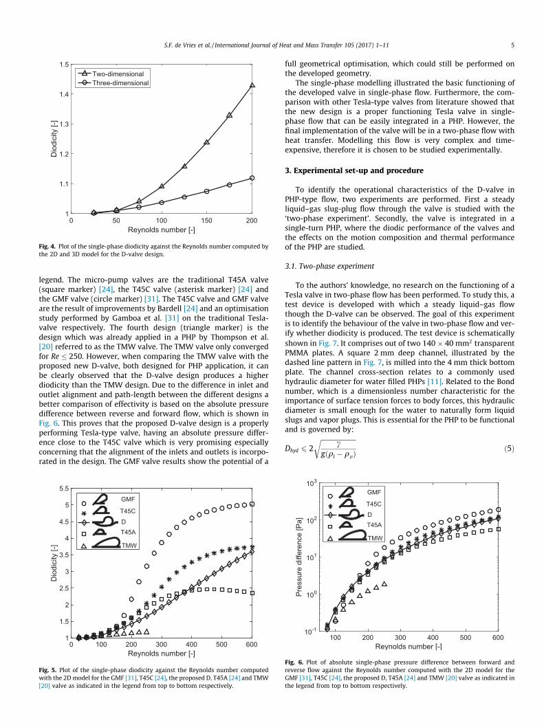
Fig. 4. Plot of the single-phase diodicity against the Reynolds number computed bythe 2D and 3D model for the D-valve design.
S.F. de Vries et al. / International Journal of Heat and Mass Transfer 105 (2017) 1–11 5
legend. The micro-pump valves are the traditional T45A valve(square marker) [24], the T45C valve (asterisk marker) [24] andthe GMF valve (circle marker) [31]. The T45C valve and GMF valveare the result of improvements by Bardell [24] and an optimisationstudy performed by Gamboa et al. [31] on the traditional Tesla-valve respectively. The fourth design (triangle marker) is thedesign which was already applied in a PHP by Thompson et al.[20] referred to as the TMW valve. The TMW valve only convergedfor Re � 250. However, when comparing the TMW valve with theproposed new D-valve, both designed for PHP application, it canbe clearly observed that the D-valve design produces a higherdiodicity than the TMW design. Due to the difference in inlet andoutlet alignment and path-length between the different designs abetter comparison of effectivity is based on the absolute pressuredifference between reverse and forward flow, which is shown inFig. 6. This proves that the proposed D-valve design is a properlyperforming Tesla-type valve, having an absolute pressure differ-ence close to the T45C valve which is very promising especiallyconcerning that the alignment of the inlets and outlets is incorpo-rated in the design. The GMF valve results show the potential of a
0 100 200 300 400 500 600Reynolds number [-]
1
1.5
2
2.5
3
3.5
4
4.5
5
5.5
Dio
dici
ty [-
]
T45A
T45C
GMF
TMW
D
Fig. 5. Plot of the single-phase diodicity against the Reynolds number computedwith the 2Dmodel for the GMF [31], T45C [24], the proposed D, T45A [24] and TMW[20] valve as indicated in the legend from top to bottom respectively.
full geometrical optimisation, which could still be performed onthe developed geometry.
The single-phase modelling illustrated the basic functioning ofthe developed valve in single-phase flow. Furthermore, the com-parison with other Tesla-type valves from literature showed thatthe new design is a proper functioning Tesla valve in single-phase flow that can be easily integrated in a PHP. However, thefinal implementation of the valve will be in a two-phase flow withheat transfer. Modelling this flow is very complex and time-expensive, therefore it is chosen to be studied experimentally.
3. Experimental set-up and procedure
To identify the operational characteristics of the D-valve inPHP-type flow, two experiments are performed. First a steadyliquid–gas slug-plug flow through the valve is studied with the‘two-phase experiment’. Secondly, the valve is integrated in asingle-turn PHP, where the diodic performance of the valves andthe effects on the motion composition and thermal performanceof the PHP are studied.
3.1. Two-phase experiment
To the authors’ knowledge, no research on the functioning of aTesla valve in two-phase flow has been performed. To study this, atest device is developed with which a steady liquid–gas flowthough the D-valve can be observed. The goal of this experimentis to identify the behaviour of the valve in two-phase flow and ver-ify whether diodicity is produced. The test device is schematicallyshown in Fig. 7. It comprises out of two 140 � 40 mm2 transparentPMMA plates. A square 2 mm deep channel, illustrated by thedashed line pattern in Fig. 7, is milled into the 4 mm thick bottomplate. The channel cross-section relates to a commonly usedhydraulic diameter for water filled PHPs [11]. Related to the Bondnumber, which is a dimensionless number characteristic for theimportance of surface tension forces to body forces, this hydraulicdiameter is small enough for the water to naturally form liquidslugs and vapor plugs. This is essential for the PHP to be functionaland is governed by:
Fig. 6. Plot of absolute single-phase pressure difference between forward andreverse flow against the Reynolds number computed with the 2D model for theGMF [31], T45C [24], the proposed D, T45A [24] and TMW [20] valve as indicated inthe legend from top to bottom respectively.
Fig. 7. Schematic image of the two-phase test device. The indicated sizes are in millimetres and the dimensions of the valves are identical to those in Fig. 2. The dashed linepattern represents the 2 mm deep channel geometry which is milled into the 4 mm thick bottom plate. IL, IG, O1 and O2 indicate the liquid inlet, gas inlet, outlet one andoutlet two respectively, which are holes through the 1 mm thick top plate. F1 and F2 indicate the field of view of the camera used for computing the bubble velocity inforward and reverse flow respectively. The flow-type, alternating liquid slug (dark grey) and gas plug (white) flow, created with this set-up is illustratively shown in the initialmeandering channel. Gravity is directed in the negative Z-direction, with the device in the XY-plane.
6 S.F. de Vries et al. / International Journal of Heat and Mass Transfer 105 (2017) 1–11
where c is the surface tension, g the gravitational constant, ql theliquid density and qv the vapor density of the working fluid [10,35].
Holes for the liquid inlet (IL), gas inlet (IG), outlet one (O1) andoutlet two (O2) are made the 1 mm thick top plate using a laser-cutter. Double-sided adhesive tape (thickness �0.1 mm), with thedashed line pattern cut-out, is used to bond the two platestogether.
The working fluid is water dyed with blue food colourant(BPOM RI MD. 263109077128) for contrast with a ratio of 125:1.Ambient air is used as the working gas. Both the working fluidand gas had a temperature of 22 �C. The water and air are simulta-neously pumped with a 1:1 volume ratio into the inlets by a syr-inge pump (Nexus 3000) using 50 ml syringes. Thereby, aperfectly slug-plug alternating flow is created with slug and pluglengths between 2 and 3 mm as illustratively shown in Fig. 7.The initial meandering channel is added to reduce fluctuations inthe flow by increasing the total flow resistance of the device. Byclosing-off one of the two outlets the direction of flow throughthe valve can be chosen. To quickly attain a steady-state flowand diminish the effect of initial distribution, the device is firstshortly flushed with a high flow rate after which the flow rate isinstantly reduced to the required value. Due to the compressibilityof the air in the syringe there is a short adjustment period afterwhich the steady-state solution for that flow rate is established.Then, using a camera (DFK 23UP031) with a 16 mm F1.6 TV lens,the flow is recorded for 9 s at a frame rate of 700 frames per sec-ond. Two repetitions were performed for each flow rate. The fieldof view for forward (F1) and reverse (F2) flow are indicated by greyrectangles in Fig. 7. Furthermore, to observe the complete flowbehaviour, several movies of the total valves were also acquiredwith a frame rate of 160 frames per second for 9 s. The device istested in a horizontal position, i.e. with the gravity field perpendi-cular to the device.
3.2. PHP experiment
Next to the two-phase test device also a single-turn PHP, madeout from polycarbonate (PC), is developed. PC is used for the goodoptical transparency, toughness and thermal properties. Water isused as a working fluid for the compatibility with PC. Two PHPs,both shown in Fig. 8, were manufactured. The left is referred toas the Normal PHP (N-PHP) and the right as Tesla-Valve PHP(TV-PHP), with the only difference being the added valves. ThePHPs are bottom-heated, i.e. the evaporator is placed below thecondenser with respect to gravity, which is the best heat moderegarding optimum functionality [10,13]. More ideally the PHPwould be tested in the horizontal configuration to disregard theinfluence of gravity. However, as Khandekar and Groll [14] and
Khandekar et al. [29] mentioned, a single-turn PHP does not func-tion in horizontal orientation. The valves are arranged symmetri-cally in order to purely test the effect of the valve on the fluidmotion, without having differences in heating and cooling area.The devices consist of two 4 � 60 � 135.5 mm3 PC plates. In theback plate, three 2 mmwide channels are milled and O-rings (EriksFKM 75 � 2 mm, 90 � 2 mm) are placed in the inner and outerchannels (1.7 mm deep). The fluid channel has a cross-section of2 � 2 mm2.
The PHPs are placed inside a vacuum chamber (Hositrad – CrossReducing 6-Way – ISO-K 160/NW16KF/NW25KF) for thermal insu-lation, which is illustratively shown in Fig. 9. Indicated with thenumber 3 in Fig. 9, a custom made aluminium block(40 � 40 � 67 mm) is attached to the back flange (Hositrad –ISO160B, indicated with number 6 in Fig. 9) of the vacuum cham-ber whereupon the PHP is attached using two M3 bolts. Thermalpaste (Electrolube – HTSP50T) is used to enhance all the thermalconnections. This block acts as a heat sink and relates to the con-denser area, initially having a 22 �C room temperature. For the eva-porator section an additional custom made aluminium block(40 � 40 � 10 mm, number 4 in Fig. 9) is attached onto the bottomside of the PHP into which a D6.5 � 40 mm heating cartridge(Mickenhagen – KA10-01778/1-100 W/220 V), indicated withnumber 5 in Fig. 9, is integrated. As a safety measure, this heatingblock is grounded and the temperature is monitored with a K-typethermocouple. The heat input for the experiments is 10 W. A cam-era (DFK 23UP031) is used with a 16 mm F1.6 TV lens to image thePHP through the glass view-port (Hositrad – HHVP-ISO160, num-ber 8 in Fig. 9) of the vacuum chamber. A frame rate of 60 framesper second is used and LED-strips consisting of 66 individual LEDs(Velleman – LB12M110CWN) are placed on the inside wall of thevacuum chamber for illumination. Furthermore, two K-type ther-mocouples located at T1 and T2, as shown in Fig. 8, were used todetermine the thermal resistance of the PHPs. Thermocouple datawas retrieved every 0.5 s.
The PHPs are evacuated with a vacuum pump (Vacuubrand - PC8/RC 6) to a level of 10�3 mbar and subsequently filled for 50% withde-gassed and de-mineralised water to which blue food colourant(BPOM RI MD. 263109077128) is added with a ratio of 125:1. ThePHP is filled using a 3-port switching valve (Upchurch V-100T)with a gas-tight syringe (Hamilton 1001 TLL SYR) and sealed witha shut-off valve (Upchurch P-732). Due to the permeable behaviourof PC the filling procedure is repeated before every experiment tohave consistent conditions. Directly after filling the PHP thevacuum pump is connected to the chamber which is evacuatedto a pressure level of 1 mbar. When this level is reached the heateris switched on and the measurement starts. For safety reasons, themaximum allowable heating block temperature is 120 �C. Due to
Fig. 8. Illustrative image of both PHPs with left the Normal PHP (N-PHP) and right the Tesla-valve PHP (TV-PHP). The sizes are in millimetres and T1 and T2 indicate thethermocouple locations. Furthermore, the evaporator section (dark grey), the adiabatic section and the condenser section (light grey) are indicated.
Fig. 9. Illustrative side view of how the PHP is positioned in the vacuum chamber.1. PHP front plate, 2. PHP back plate, 3. Cooling block, 4. Heating block, 5. Cartridgeheater, 6. Back flange of vacuum chamber, 7. Vacuum chamber, 8. Glass view-port.
S.F. de Vries et al. / International Journal of Heat and Mass Transfer 105 (2017) 1–11 7
the relative high thermal resistance of the polycarbonate, no equi-librium temperatures could be attained before this maximum tem-perature heating block was reached. Therefore the transientbehaviour of the PHPs is measured for 30 min. Three experimentsare performed for each heat pipe. The energy balance of this sys-tem can be written as:
where qin is the heat input from the cartridge heater (10 W), qcond
the heat that is conducted through the device and attached cables,qconv the heat loss to the environment by convection, qrad theradiated heat to the environment and qtransferthe actual transferredheat by the working fluid. qstored is the stored sensible heat, sincethe transient behaviour is considered. In order to distinguish theqex, three additional measurements are performed for each PHPwhere the temperature rise of the evacuated but unfilled PHPs ismeasured. The maximum contribution of the stored sensible heatin the water, based on the maximum possible temperature rise of98 �C of the water over 30 min, is less than 1% of the total heat inputand can therefore be neglected. The total power-use of the LEDs is4 W of which a large amount is converted into heat. The strips areplaced, sufficiently far away from the back flange, inside thevacuum chamber on the wall which acts as a heat sink. Therefore,due to the high thermal mass of the vacuum chamber wall andthe natural convection on the outside of the chamber, the influenceof this heat to the system can be neglected.
3.3. Image analysis
The Image Processing Toolbox of MATLAB [36] is used to pro-cess the acquired data. For the two-phase experiment, image regis-tration [37] is used to compute the movement of the bubbles in thevalve between two successive frames. A masking procedure isapplied, as shown in Fig. 10, to separately process the inlet (1)and side channel (2) of the valve. With the translation of each sec-tion between two successive frames the bubble velocity can bedetermined.
The acquired movies of the total valves can be used to deter-mine the air–water volume ratio throughout the valve, defined as/ ¼ Vair=Vwater . The grey-scale images are converted into binaryimages using a threshold, as shown in Fig. 10, in which whiterepresents air and black represents water. Using the maskingprocedure illustrated in Fig. 10, the air–water volume ratio inboth channels can be determined separately for each frame.The accuracy of the method is determined by averaging the
Fig. 10. Masking procedures used for the two-phase experiment. The left imageshows masking procedure used for image registration, where 1 indicates the inletchannel section and 2 the side channel section. The right image shows the appliedmasks for determining the air ratio in the main (A) and side (B) valve channel. Anindividual grey-scale frame of a reverse flow case with and average inlet velocity of0.21 m/s is shown on top and below the corresponding binary image.
0.1
0.15
0.2
0.25
cha
nnel
vel
ocity
[m/s
]
Reverse - experiment - two-phaseForward - experiment - two-phaseReverse - model - single-phaseForward - model - single-phase
8 S.F. de Vries et al. / International Journal of Heat and Mass Transfer 105 (2017) 1–11
time-averaged / of both channels and comparing this with the pre-scribed 1:1 volume ratio. This showed to maximally deviate 3%.
In the PHP experiment the total PHPs are imaged by the camerato examine the motion when this is consistent, i.e. in a quasi-steady state as defined by Khandekar et al. [29]. The velocity ofthe flow is determined with the centre-of-mass method [38]. Boththe left and the right part of the loop, thus including valves for theTV-PHP, are processed separately. The top and bottom part of theloop are discarded due to the thermocouples and shut-off valvepartly blocking the view of the channel. For each frame, for bothchannels, the background is subtracted and the grey-level-weighted centre-of-mass is determined. A velocity is computedwith the longitudinal difference of the centre-of-mass locationbetween two subsequent frames. Since the valves also distributefluid in the transverse direction this centre-of-mass method isused. The acquired velocity is therefore representable for the fluidtransport.
A circulation-tally-ratio (CTR), defined by Thompson et al. [20]as the ratio of the number of occurrences of counter-clockwise(CCW) over clockwise (CW) circulatory flow, is calculated usingthe same criteria as Thompson et al. [20].
CTR ¼P
CCWPCW
ð7Þ
Circulatory flow relates to almost all the fluid located in thecondenser being moved through the evaporator and (partly)moved back to the condenser again. The CTR indicates in whichdirection circulation is promoted.
0 0.05 0.1 0.15 0.2 0.25 0.3Inlet velocity [m/s]
0
0.05Side
Fig. 11. Plot of the measured bubble velocity in the side channel (us) of the valve forboth flow directions against the prescribed mean inlet velocity (uin) with thestandard deviation indicated as error bars. The mean side channel velocity versusthe mean inlet velocity computed with the 3D single-phase model for water at22 �C is also shown for comparison. The modelled forward flow is only plotted up toRe ¼ 200 due to non-convergence of the model for higher Re.
4. Results
4.1. Two-phase experiment
The measured side channel bubble velocity us plotted againstthe mean inlet velocity uin, based on the prescribed total flow rate,is shown in Fig. 11 for both flow directions. The measured inletchannel bubble velocity showed to have a maximum deviation of5% from uin, at the highest flow rate. As a reference, the mean sidechannel velocity computed with the single-phase 3D model forwater at 22 �C is plotted versus the mean inlet velocity. The range
of the forward case is limited by the non-convergence of the modelfor Re > 200. Blockage of the side channel by air bubbles occurredfor lower flow rates for both flow directions. Meaning that afterflushing, the flow in the side channel would stagnate and the totalflow would go through the main channel. In that case the appliedpressure on the side channel is not large enough for the bubbles toremain dynamic[39]. The side channel was blocked up touin 0:24 m/s for forward and uin 0:16 m/s for reverse flow.Moreover, as can be observed in Fig. 11, a significant differenceexists between the forward and reverse side channel velocity us.
The air–water distribution was not identical for the main andside channel of the valve for reverse flow, but a factor of about2.3 higher in the main channel than in the side channel as is shownin Table 2. For forward flow at uin 0:24 m/s, the air–water ratiosfor the main and side channel were similar. Considering the accu-racy of the method, this indicates that the air–water distributiondoes not change throughout the valve in forward flow. In addition,the bubbles were almost never split-up in forward flow. In the con-trary, for higher inlet velocities, the sharp point of the middle sec-tion in junction 2 often splits up bubbles in reverse flow resultinginto two smaller bubbles moving through the main and side chan-nel separately. This phenomena can also be seen in Fig. 10.
A clear difference between the modelled single-phase and mea-sured side channel velocity is observed. This could be caused byprincipal differences between two-phase and single-phase flowlike surface tension effects, gas compressibility or momentum dif-ferences between gas and liquid. Yet, since the bubbles do notalways completely block the side channel in reverse flow, it cannotbe ruled out that this difference can also be related to the liquidflowing past the bubbles in the side channel resulting in a differ-ence of fluid velocity and measured bubble velocity.
The difference in blockage, redistribution of working fluid anddifference in velocity indicate that there is a large difference ofmass flow distribution between the different directions. Since dio-dicity is produced by a difference in flow distribution, this can berelated to a difference in flow resistance based on the structureof the valve. Unfortunately, the absolute value of this diodicity intwo-phase flow could not be measured. Measuring this wouldrequire very accurate (4p � 102 � 103 Pa), properly applied andin two-phase flow applicable pressure sensors. Nonetheless, the
Table 2Measured air–water distributions in the main and side channels of the Tesla valves(defined according to Fig. 10) for a reverse and forward flow case.
Flow direction Air–water ratio in mainchannel
Air–water ratio in sidechannel
Reverse flow(uin 0.24 m/s)
Um = 1.46 Us = 0.64
Forward flow(uin 0.24 m/s)
Um = 0.98 Us = 1.01
S.F. de Vries et al. / International Journal of Heat and Mass Transfer 105 (2017) 1–11 9
side channel velocities could be measured and showed similarbehaviour for the single-phase model and two-phase experiments.Therefore, the main goal of this experiment, which was to find thetwo-phase flow characteristics of the valve and verify whether dio-dicity is produced, is achieved.
4.2. PHP experiment
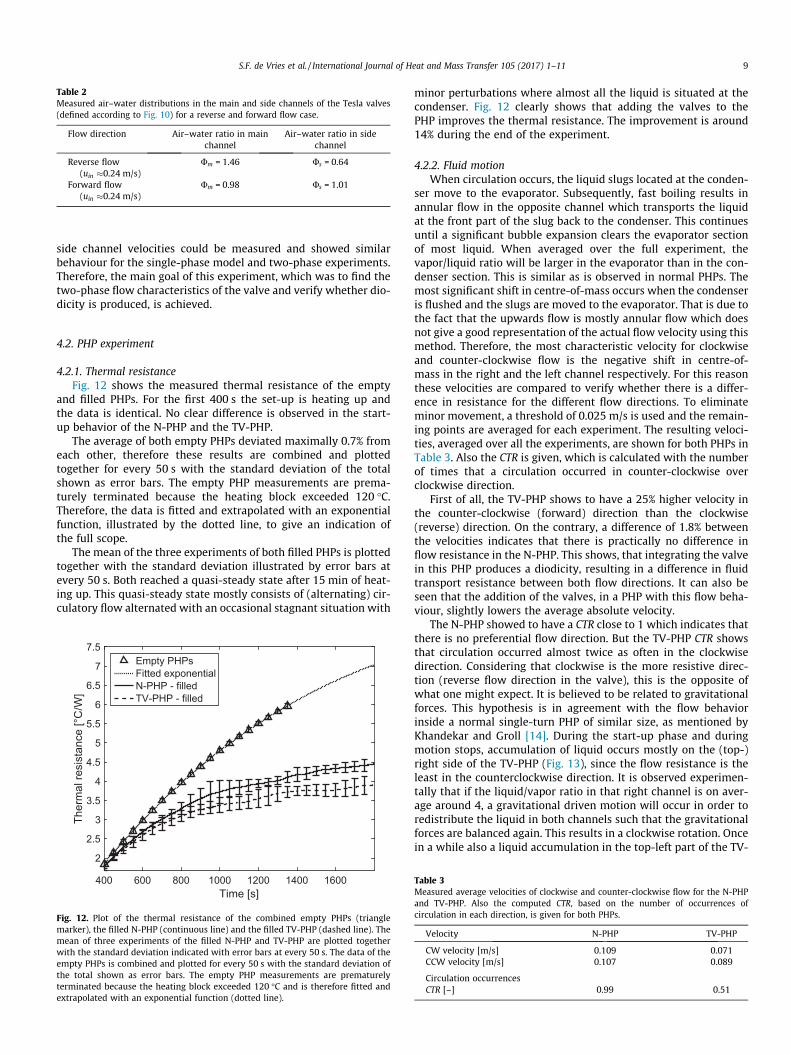
4.2.1. Thermal resistanceFig. 12 shows the measured thermal resistance of the empty
and filled PHPs. For the first 400 s the set-up is heating up andthe data is identical. No clear difference is observed in the start-up behavior of the N-PHP and the TV-PHP.
The average of both empty PHPs deviated maximally 0.7% fromeach other, therefore these results are combined and plottedtogether for every 50 s with the standard deviation of the totalshown as error bars. The empty PHP measurements are prema-turely terminated because the heating block exceeded 120 �C.Therefore, the data is fitted and extrapolated with an exponentialfunction, illustrated by the dotted line, to give an indication ofthe full scope.
The mean of the three experiments of both filled PHPs is plottedtogether with the standard deviation illustrated by error bars atevery 50 s. Both reached a quasi-steady state after 15 min of heat-ing up. This quasi-steady state mostly consists of (alternating) cir-culatory flow alternated with an occasional stagnant situation with
Fig. 12. Plot of the thermal resistance of the combined empty PHPs (trianglemarker), the filled N-PHP (continuous line) and the filled TV-PHP (dashed line). Themean of three experiments of the filled N-PHP and TV-PHP are plotted togetherwith the standard deviation indicated with error bars at every 50 s. The data of theempty PHPs is combined and plotted for every 50 s with the standard deviation ofthe total shown as error bars. The empty PHP measurements are prematurelyterminated because the heating block exceeded 120 �C and is therefore fitted andextrapolated with an exponential function (dotted line).
minor perturbations where almost all the liquid is situated at thecondenser. Fig. 12 clearly shows that adding the valves to thePHP improves the thermal resistance. The improvement is around14% during the end of the experiment.
4.2.2. Fluid motionWhen circulation occurs, the liquid slugs located at the conden-
ser move to the evaporator. Subsequently, fast boiling results inannular flow in the opposite channel which transports the liquidat the front part of the slug back to the condenser. This continuesuntil a significant bubble expansion clears the evaporator sectionof most liquid. When averaged over the full experiment, thevapor/liquid ratio will be larger in the evaporator than in the con-denser section. This is similar as is observed in normal PHPs. Themost significant shift in centre-of-mass occurs when the condenseris flushed and the slugs are moved to the evaporator. That is due tothe fact that the upwards flow is mostly annular flow which doesnot give a good representation of the actual flow velocity using thismethod. Therefore, the most characteristic velocity for clockwiseand counter-clockwise flow is the negative shift in centre-of-mass in the right and the left channel respectively. For this reasonthese velocities are compared to verify whether there is a differ-ence in resistance for the different flow directions. To eliminateminor movement, a threshold of 0.025 m/s is used and the remain-ing points are averaged for each experiment. The resulting veloci-ties, averaged over all the experiments, are shown for both PHPs inTable 3. Also the CTR is given, which is calculated with the numberof times that a circulation occurred in counter-clockwise overclockwise direction.
First of all, the TV-PHP shows to have a 25% higher velocity inthe counter-clockwise (forward) direction than the clockwise(reverse) direction. On the contrary, a difference of 1.8% betweenthe velocities indicates that there is practically no difference inflow resistance in the N-PHP. This shows, that integrating the valvein this PHP produces a diodicity, resulting in a difference in fluidtransport resistance between both flow directions. It can also beseen that the addition of the valves, in a PHP with this flow beha-viour, slightly lowers the average absolute velocity.
The N-PHP showed to have a CTR close to 1 which indicates thatthere is no preferential flow direction. But the TV-PHP CTR showsthat circulation occurred almost twice as often in the clockwisedirection. Considering that clockwise is the more resistive direc-tion (reverse flow direction in the valve), this is the opposite ofwhat one might expect. It is believed to be related to gravitationalforces. This hypothesis is in agreement with the flow behaviorinside a normal single-turn PHP of similar size, as mentioned byKhandekar and Groll [14]. During the start-up phase and duringmotion stops, accumulation of liquid occurs mostly on the (top-)right side of the TV-PHP (Fig. 13), since the flow resistance is theleast in the counterclockwise direction. It is observed experimen-tally that if the liquid/vapor ratio in that right channel is on aver-age around 4, a gravitational driven motion will occur in order toredistribute the liquid in both channels such that the gravitationalforces are balanced again. This results in a clockwise rotation. Oncein a while also a liquid accumulation in the top-left part of the TV-
Table 3Measured average velocities of clockwise and counter-clockwise flow for the N-PHPand TV-PHP. Also the computed CTR, based on the number of occurrences ofcirculation in each direction, is given for both PHPs.
Fig. 13. Snapshot of the filling pattern in a TV-PHP (dark areas: liquid slugs, lightareas: vapor plugs). A liquid accumulation is seen at the top-right side of the TV-PHP leading to a clockwise circulatory motion. The gravitational field is pointingdownwards.
10 S.F. de Vries et al. / International Journal of Heat and Mass Transfer 105 (2017) 1–11
PHP was observed, although this occurs less frequently due to thediodicity of the valves. Also in that situation a counterclockwiesemotion occurred at the moment that the liquid/vapor ratio is alsoon average around 4, indicating the gravity effect.
If the device is placed horizontally (thus g ¼ 0) no fluid motionwill occur for temperatures up to 120 �C, which is in agreementwith the gravity hypothesis. This behavior is representative forboth N-PHP and TV-PHP and it is in agreement with the literature[14]. It is expected that by increasing the number of turns of theTV-PHP the influence of gravity will decrease, as is already shownfor standard PHPs [19,21]. Furthermore, by decreasing the channeldimensions of the TV-PHP, the relative importance of thediodic-induced pressure differences over gravitational pressuredifferences will increase as well and therefore a circulatory flowin forward direction is expected.
Due to the relatively simple flow behaviour of the used single-turn PHP, the characteristics of applying Tesla valves in pulsatingheat pipes are made more clear. The most important result is thatintegrating the valves into the PHP improves the heat transfer per-formance and produces a diodicity, which was the main objectiveof the experiment. When applied in a bottom-heated single-turnPHP of these dimensions, produced gravitational differences aremore likely to promote circulation.
5. Conclusions
A new Tesla-type passive valve is successfully designed forimplementation in a PHP. Laminar single-phase modellingrevealed that the proposed valve geometry functions as a properTesla-type valve compared to other designs from literature, produ-cing significant diodicity also at lower Reynolds numbers. A steadyslug-plug flow through the valve is optically studied to verify thetwo-phase flow behaviour. A large difference between forwardand reverse volume flow distribution was observed. Also, a redis-tribution of air–water ratio between the valve channels wasobserved for reverse flow, while this remained the same in forwardflow. The large difference in mass distribution in both valve chan-nels between forward and reverse flow indicate that diodicity isproduced in two-phase flow.
The valve is implemented in a single-turn transparentbottom-heated PHP to study its effect on the heat transfer and flowbehaviour. The valve produced diodicity, which resulted into a dif-ference of 25% in velocity for the different flow directions. Due tothe gravitational influence on the flow in a PHP of these dimen-sions, the diodicity of the symmetrically placed valves resulted ina promotion of circulation in the more resistive direction by a fac-tor of almost 2. The addition of the valves resulted in a decrease ofthermal resistance of around 14%, when compared to an identicalPHP without valves.
The developed experimental set-ups and procedures are shownto be effective and low-cost tools to study two-phase flow withheat transfer phenomena in a Tesla-type valve. The proposed valveshowed to improve the thermal performance of the PHP, producediodicity and create preferential motion. However, when appliedin a gravity dependent PHP, the valve placement should be suchthat the valves produce gravitational differences which promotecirculation in the desired direction. Decreasing the channeldimension of the PHP increases the relative importance of thediodic-induced pressure differences over gravitational pressuredifferences. This study shows that features can be incorporatedwhich can improve the thermal performance of pulsating heatpipes and that Tesla valves should be considered as a viable optionfor the promotion of circulation in pulsating heat pipes.
Acknowledgement
This research is supported by the Dutch Technology FoundationSTW (Grant No 11734), which is part of the Netherlands Organiza-tion for Scientific Research (NWO), and which is partly funded bythe Ministry of Economic Affairs, Agriculture and Innovation.
References
[1] M. Ebadian, C. Lin, A review of high-heat-flux heat removal technologies, J.Heat Transfer 133 (11) (2011) 110801.
[2] I. Mudawar, Assessment of high-heat-flux thermal management schemes, IEEETrans. Compon. Packag. Technol. 24 (2) (2001) 122–141.
[3] A. Fagri, Heat pipes: review, opportunities and challenges, Front. Heat Pipes 5(1) (2014) 1379–1387.
[4] H. Akachi, Structure of a heat pipe, patentnumber 4921041, 1990.[5] X. Han, X. Wang, H. Zheng, X. Xu, G. Chen, Review of the development of
pulsating heat pipe for heat dissipation, Renewable Sustainable Energy Rev. 59(2016) 692–709.
[6] M. Shaffii, A. Faghri, Y. Zhang, Thermal modelling of unlooped and loopedpulsating heat pipes, ASME J. Heat Transfer 123 (2001) 1159–1172.
[7] B. Tong, T. Wong, K. Ooi, Closed-loop pulsating heat pipe, Appl. Therm. Eng. 21(2001) 1845–1862.
[8] J. Xu, Y. Li, T. Wong, High speed flow visualization of a closed-loop pulsatingheat pipe, Int. J. Heat Mass Transfer 48 (2005) 3338–3351.
[9] S. Liu, J. Li, X. Dong, H. Chen, Experimental study of flow patterns and improvedconfigurations for pulsating heat pipes, J. Therm. Sci. 16 (1) (2006) 56–62.
[10] Y. Zhang, A. Faghri, Advances and unsolved issues is pulsating heat pipes, HeatTransfer Eng. 29 (1) (2008) 20–44.
[11] X. Tang, L. Sha, H. Zhang, Y. Ju, A review of recent experimental investigationsand theoretical analysis for pulsating heat pipes, Front. Energy 7 (2) (2013)161–173.
[12] S. Khandekar, N. Dollinger, M. Groll, Understanding operational regimes ofclosed loop pulsating heat pipes: an experimental study, Appl. Therm. Eng. 23(2003) 707–719.
[13] K.-H. Chien, Y.-T. Lin, Y.-R. Chen, K.-S. Yang, C.-C. Wang, A novel design ofpulsating heat pipe with fewer turns applicable to all orientations, Int. J. HeatMass Transfer 55 (2012) 5722–5728.
[14] S. Khandekar, M. Groll, An insight into thermo-hydrodynamic coupling inclosed loop pulsating heat pipes, Int. J. Therm. Sci. 43 (2004) 13–20.
[15] S. Thompson, H. Ma, A statistical analysis on temperature oscillations on a flat-plate oscillating heat pipe with tesla-type check valves, Front. Heat Pipes 2(2011) 033002.
[16] D. Mangini, M. Mameli, A. Georgoulas, L. Araneo, S. Filippeschi, M. Marengo, Apulsating heat pipe for space applications: Ground and microgravityexperiments, Int. J. Therm. Sci. 95 (2015) 53–63.
[17] N. Bhuwakietkumjohn, S. Rittidech, Internal flow patterns on heat transfercharacteristics of a closed-loop oscillating heat-pipe with check valves usingethanol and a silver nano-ethanol mixture, Exp. Therm. Fluid Sci. 34 (2010)1000–1007.
S.F. de Vries et al. / International Journal of Heat and Mass Transfer 105 (2017) 1–11 11
[18] B. Holley, A. Faghri, Analysis of pulsating heat pipe with capillary wick andvarying channel diameter, Int. J. Heat Mass Transfer 48 (2005) 2635–2651.
[19] G. Kwon, S. Kim, Operational characteristics of pulsating heat pipes with adual-diameter tube, Int. J. Heat Mass Transfer 75 (2014) 184–195.
[20] S. Thompson, H. Ma, C. Wilson, Investigation of a flat-plate oscillating heatpipe with tesla-type check valves, Exp. Therm. Fluid Sci. 35 (2011) 1265–1273.
[21] P. Charoensawan, S. Khandekar, M. Groll, Closed loop pulsating heat pipes parta: parametric experimental investigations, Appl. Therm. Eng. 23 (2003) 2009–2020.
[22] F. Foster, R. Bardell, M. Afromowitz, N. Sharma, A. Blanchard, Design,fabrication and testing of fixed-valve micro-pumps, ASME Fluids Eng. Div.234 (1995) 39–44.
[23] A. Fadl, Z. Zhang, M. Faghri, D. Meyer, E. Simmon, Experimental investigationof geometric effect on micro fluidic diodicity, in: 5th International Conferenceon Nano-, Micro- and Minichannels, 2007.
[24] R. Bardell, The diodicity mechanism of tesla-type no-moving-parts valves,University of Washington, 2000.
[25] A. Fadl, Z. Zhang, S. Geller, J. Tlke, M. Krafczyk, D. Meyer, The effect of themicrofluidic diodicity on the efficiency of valve-less rectification micropumpsusing lattice-boltzmann method, Microsyst. Technol. 15 (2009) 1379–1387.
[26] N. Tesla, Valvular conduit, patentnumber US 1329559 A, 1920.[27] K. Mohammadzadeh, E. Kolahdouz, E. Shirani, M. Shafii, Numerical
investigation on the effect of the size and number of stages on the teslamicrovalve efficiency, J. Mech. 29 (3) (2013) 527–534.
[28] B. Paudel, T. Jamal, S. Thompson, D. Walters, Thermal effects on micro-sizedtesla valves, in: ASME 12th International Conference on Nanochannels,Microchannels, and Minichannels, 2014, p. V002T19A006.
[29] S. Khandekar, A. Gautam, P. Sharma, Multiple quasi-steady states in a closedloop pulsating heat pipe, Int. J. Therm. Sci. 48 (2009) 535–546.
[30] Comsol multiphysics 5.0, https://www.comsol.com (01-2016).[31] A. Gamboa, C. Morris, F. Forster, Improvements in fixed-valve micropump
performance through shape optimization of valves, J. Fluids Eng. 127 (2005)339–346.
[32] S. Thompson, P. Paudel, T. Jamal, D. Walters, Numerical investigation ofmultistaged tesla valves, J. Fluids Eng. 136 (2014) 081102.
[33] F. Forster, B. Williams, Parametric design of fixed-geometry microvalves – thetesser valve, in: Proceedings of IMECE2002, 2002, pp. 431–437.
[34] F. White, Fluid Mechanics, McGraw-Hill, New York, 1986.[35] S. Khandekar, M. Groll, On the definitions of pulsating heat pipes: an overview,
[36] The mathworks inc., http://nl.mathworks.com/products/image/ (01-2016).[37] The mathworks inc., http://nl.mathworks.com/discovery/image-registration.
html (01-2016).[38] The mathworks inc., http://nl.mathworks.com/matlabcentral/fileexchange/
41675-center-of-mass (01-2016).[39] M. Mohammmadi, K. Sharp, The role of contact line (pinning) forces on bubble
blockage in microchannels, J. Fluids Eng. Trans. ASME 173 (3) (2015) 0312081.