Design and Operation of Small to Medium scale Oil-spill Cleaning Units By O. Turan and D. Konovessis, Universities of Glasgow and Strathclyde, United Kingdom Nikolaos P. Ventikos, NTUA, Greece P. Lemesle (1) Bureau Mauric, France, N. M. P. Kakalis and Y.P. Ventikos, University of Oxford, United Kingdom D. Fritsch, IPA, Germany Abstract Oil pollution, which may be either from marine accidents or from standard ship operations, is dangerous to the marine environment, with possible long term effects. The degree of damage depends on the amount of oil spilled, the geographical and environmental conditions as well as nature of the marine life in the area. The cost of cleaning up and the damage caused could go into billions of Euros. There are various methods which have been used to combat and minimise the oil spill damage, and the reaction time to the oil spill is an extremely important factor in determining the amount of oil that can be collected before spreading to shorelines, where the cleaning costs are significantly higher. EU-MOP Research project in EU FP6 programme deals with the design and proof of the autonomous Elimination Units for Marine Oil Pollution (EU-MOPs) which are capable of mitigating and eliminating the threat arising from small and medium oil spill incidents. The end-result of this project will be the conceptual development and validation of low cost, possibly recyclable, autonomous vessels/drones that will be released in the oil spill area, will automatically (through proper sensors) track the oil concentration specifics of the spill, and will apply either mechanical or chemical countermeasures locally. One of the objectives is to propose a cost effective design while reducing the direct contact of humans with the spills. The paper presents the Monocat design concept, which is based on a monohull form with a catamaran bow. The system is proposed especially for small to medium spills in shallow and closed areas. The sizes of the units vary between 2.4 and 3.5 meters while storing up to 2 tones of skimmed oil. The paper explains the details of the autonomous and self propelled concept which covers the oil detecting, skimming, storing and disposing. The paper further explains the technical challenges due to their sizes together with the most efficient use of such devices. 1.0 INTRODUCTION The key factor for efficient clean-up operations is to develop an adequate structure focusing on the confrontation of oil when this is floating into the sea. It is documented that the clean-up costs rises at least 10 times when the oil reaches at a significant portion of the shore [1]. This means that a well-planned operation should try to confront the oil when this is still into the sea and diminish its possibilities to impact the nearby coasts. Moreover, the means utilized in the outline of oil confrontation efforts should be able to operate sufficiently under all weather conditions and reflect to low and reasonable running costs. These two parameters may affect the overall outcome (e.g. lead the oil spill counteraction to inadequate or unpractical performance and solutions) and therefore they should be dealt determinately and with extreme caution. The issues of oil marine pollution and oil spill confrontation have attracted increasing research efforts over the past 25-30 years. The preservation of the marine environment is of extreme importance and therefore all possible dangers-problems that threaten it must be dealt with determination and efficiency. In this context, the MIT Grand Project 1982 has contributed significantly in the areas of the strategic planning (e.g. through the optimization of an effective anti-pollution network) and of tactical response management (utilizing optimization techniques for the overall capability of the examined counter oil equipment) [1], [2]. Additionally, innovative structured approaches concerning the causes, the escalation phase and the impact (consequences) of oil spill accidents are in position to enhance the scenario analysis and reveal useful trends and practices that should be dealt with extreme caution. Moreover, the integration of this problem with safety techniques (e.g. fault trees, event trees, risk contribution trees, HAZOP etc) presents the necessary potential to compose an efficient operational framework in terms of danger awareness, spill prevention and adequate pollution confrontation [3]. This way research can satisfy IMO’s intentions for safer and cleaner seas.
Transcript
Design and Operation of Small to Medium scale Oil-spill Cleaning Units By
O. Turan and D. Konovessis, Universities of Glasgow and Strathclyde, United Kingdom Nikolaos P. Ventikos, NTUA, Greece
P. Lemesle (1) Bureau Mauric, France, N. M. P. Kakalis and Y.P. Ventikos, University of Oxford, United Kingdom
D. Fritsch, IPA, Germany Abstract Oil pollution, which may be either from marine accidents or from standard ship operations, is dangerous to the marine environment, with possible long term effects. The degree of damage depends on the amount of oil spilled, the geographical and environmental conditions as well as nature of the marine life in the area. The cost of cleaning up and the damage caused could go into billions of Euros. There are various methods which have been used to combat and minimise the oil spill damage, and the reaction time to the oil spill is an extremely important factor in determining the amount of oil that can be collected before spreading to shorelines, where the cleaning costs are significantly higher. EU-MOP Research project in EU FP6 programme deals with the design and proof of the autonomous Elimination Units for Marine Oil Pollution (EU-MOPs) which are capable of mitigating and eliminating the threat arising from small and medium oil spill incidents. The end-result of this project will be the conceptual development and validation of low cost, possibly recyclable, autonomous vessels/drones that will be released in the oil spill area, will automatically (through proper sensors) track the oil concentration specifics of the spill, and will apply either mechanical or chemical countermeasures locally. One of the objectives is to propose a cost effective design while reducing the direct contact of humans with the spills.
The paper presents the Monocat design concept, which is based on a monohull form with a catamaran bow. The system is proposed especially for small to medium spills in shallow and closed areas. The sizes of the units vary between 2.4 and 3.5 meters while storing up to 2 tones of skimmed oil. The paper explains the details of the autonomous and self propelled concept which covers the oil detecting, skimming, storing and disposing. The paper further explains the technical challenges due to their sizes together with the most efficient use of such devices. 1.0 INTRODUCTION The key factor for efficient clean-up operations is to develop an adequate structure focusing on the confrontation of oil when this is floating into the sea. It is documented that the clean-up costs rises at least 10 times when the oil reaches at a significant portion of the shore [1]. This means that a well-planned operation should try to confront the oil when this is still into the sea and diminish its possibilities to impact the nearby coasts. Moreover, the means utilized in the outline of oil confrontation efforts should be able to operate sufficiently under all weather conditions and reflect to low and reasonable running costs. These two parameters may affect the overall outcome (e.g. lead the oil spill counteraction to inadequate or unpractical performance and solutions) and therefore they should be dealt determinately and with extreme caution. The issues of oil marine pollution and oil spill confrontation have attracted increasing research efforts over the past 25-30 years. The preservation of the marine environment is of extreme importance and therefore all possible dangers-problems that threaten it must be dealt with determination and efficiency. In this context, the MIT Grand Project 1982 has contributed significantly in the areas of the strategic planning (e.g. through the optimization of an effective anti-pollution network) and of tactical response management (utilizing optimization techniques for the overall capability of the examined counter oil equipment) [1], [2]. Additionally, innovative structured approaches concerning the causes, the escalation phase and the impact (consequences) of oil spill accidents are in position to enhance the scenario analysis and reveal useful trends and practices that should be dealt with extreme caution. Moreover, the integration of this problem with safety techniques (e.g. fault trees, event trees, risk contribution trees, HAZOP etc) presents the necessary potential to compose an efficient operational framework in terms of danger awareness, spill prevention and adequate pollution confrontation [3]. This way research can satisfy IMO’s intentions for safer and cleaner seas.
There are different projects which addresses of oil spills from different angle. The European project POP&C addresses the oil control constituent for the post-spill activities, provided that the pollution in generated by a tanker accident. It is very important to note that the development of the proper mitigation framework demands integrated approaches and promotes the importance of risk, prevention and oil combat. The Greek project AEGEAN is also focusing on the risk of tanker accidents and on the necessary post spill actions in order to mitigate the consequences of vessel spills in the Aegean Sea [4]. The vessel is expected to sail within an optimized sea-route (from safety point-of-view) and the implemented oil-confronting capabilities are to be able to accommodate potential pollution needs and to meet all IMO’s demands. EU-MOP stands for “Elimination Units for Marine Oil Pollution” and is a research project co-funded by the European Commission, Directorate General for Research and Technological Development, in the context of the 6th Framework Programme. The project started in February of 2005 and has a duration of 3 years. The EU-MOP consortium is coordinated by the National Technical University of Athens (Greece), and also includes as partners the University of Glasgow and Strathclyde (UK), Sirehna S.A. (France), Instituto de Soldadura e Qualidade (Portugal), BMT Ltd (UK), Cetemar S.L. (Spain), Environmental Protection Engineering S.A. (Greece), Aurensis S.L. (Spain), the University of Oxford (UK), Consultrans S.A. (Spain), Bureau Mauric S.A. (France), the Institute of Shipping Economics and Logistics (Germany) and IPA Fraunhofer (Germany).
The specific objectives of the EU-MOP concept are to: 1. Develop innovative intelligent robot technologies for oil spill management; 2. Design and set the basic principles of these autonomous units for oil spill confrontation 3. Formulate an integrated structure for oil spill management and logistics at both the strategic and tactical levels; 4. Introduce an advanced structure (dissemination) concerning oil pollution response policy.
2.0 OPERATIONAL AND TECHNICAL REQUIREMENTS FOR EU-MOP UNITS
The design of EU-MOP unit should be evaluated in accordance with its ultimate aim of the effective and innovative oil spill control. The innovation lies in the way units responding and controlling the oil spill. The success for the oil response and control unit lies in the following steps:
• Minimal response time • Efficient and fast concentration of the widely spread oil • Adaptability to weather conditions • Skimmers and pumps which can handle viscosity emulsion and debris • Appropriate temporary storage capability • Easy clean-up and storage facility • Working as a group of units to clean the oil effectively
The operational and technical requirements have been largely envisaged based on the above points, although not necessarily to include all systems i.e. instead of some mechanical parts, if possible, offering innovative alternatives. Swarm strategies are simple rules which enable a flexible, robust and self-organizing swarm to efficiently cope with its tasks. In the EU-MOP context, these strategies will be linked with different identified scenarios, e.g. swarm strategies for the elimination of oil pollution at the open sea under bad weather conditions, or for the elimination of pollutions in harbors. Communication plays a major role in multi robot systems. It enables the system to increase its performance tremendously (Figure 1)
Figure 1: Interaction between the units of a multi robot system via communication.
2.1 EU-MOP oil spill scenario targets and Design Requirement
Oil spill control requirements can be defined by formulating appropriate oil spill scenarios. In the context of the EU-MOP units, they have been classified in three groups, which are summarised as follows: • Type of sea area: Open ocean area (sea type I), enclosed seas (sea type II, including the Mediterranean Sea with
the possible exception of the sea area between Sardegna, France and the Balearic islands, Baltic Sea and Black Sea) and shallow water areas (type III, estuaries, rivers, lakes, ambers, inlets).
• Quantity: Small spills (less than 7 tons of oil), medium size spills (7 to 700 tons) and large spills (>700 tons). • Type of oil: Two basic types of oil were being examined: light oils (non persistent like diesel oil) and persistent
oils (heavy fuel oil or crude oil). The initial definition of oil spill scenarios and mission requirement has led to preliminary definition of geometry, hull hydrodynamic characteristics as well as the energy systems for operation and propulsion.
O il S p ill S c e n a r io sM a rin e O il P o llu tio n S ta tu s
O p e ra tio n a l R e q u ire m e n ts /L im ita tio n s
D e s ig n /C o n s tru c tio n a l R e q u ire m e n ts
H y d ro d y n a m ic s E n e rg y S y s te m s S tru c tu ra l a n a ly s is
E U -M O P U n it
O il S p ill S c e n a r io sM a rin e O il P o llu tio n S ta tu s
O p e ra tio n a l R e q u ire m e n ts /L im ita tio n s
D e s ig n /C o n s tru c tio n a l R e q u ire m e n ts
H y d ro d y n a m ic s E n e rg y S y s te m s S tru c tu ra l a n a ly s is
E U -M O P U n it
Figure 2 EU-MOP Unit(s) design process
These two aspects include a number of parameters that can be shown in Figure 2. In the marine application, the all
onsidering the discussion taken place on the possible design alternatives for EU-MOP units(s), following design
hydrodynamic and energy systems are defined for the selected range, operational conditions and power (speed/energy consumption). The system’s design shape will also play major factor to define resistance related optimum speed for energy consumption and subsequent propulsion system. Cenvelope has been derived for the EU-MOP unit. The brief justification of the selected parameters are given in the following chapter for the individual design and hydrodynamic aspects.
P r o p u ls io n S e le c t io n
O p e r a t io n a l • D e e p w a te r , s h a l lo w w a te r e tc .• E n v ir o n m e n t : o i l th ic k n e s s e tc .• H y d r o d y n a m ic c h a r a c te r is t ic s( S ta b i l i ty , e f f ic ie n c y , c o n tr o l )
• E n g in e s y s te m s• S t r u c tu r a l s t r e n g th
• S p e e d• O p e r a t io n a l r a n g e
D e s ig n /M is s io n • L im i ta t io n s o f o i l s p i l l in m is s io n .
• C o s t l im i t s o n m a te r ia l s .• M a x . a n d m in . d e s ig n s iz e• S tr u c tu r a l l im i ta t io n s w i th
e n e r g y s y s te m s• C a p a c i ty
Figure 3: Propulsion selection
eneral requirements can be listed as follows;
• Power required: 5– 30Kw uel Cells or diesel Electric Engines
ility: 200 tns sh / Disc / Rope
per unit for the large unit
ric motors with propellers or Water Jets s
Skimmer types
G
• Energy source: Batteries, F• Power Autonomy: 24hrs • Group Oil Recover Capab• Skimming Devices for examination: Bru• Sea State: 2 meters • Storage tank: 2.0 m3
• Speed: up to 5 knots (transit speed) • Length: < 3m • Propulsion: Elect• Robotics: Oil Sensors / No Sensors – Leaders / No Leader
red different alternatives, the two concepts shown in Fig. 4 have been identified as the EU-MOP
ess ystems in different ranges
Having consideskimmers units. Their selection is based on the a number of parameters:
• Operability under different oil slick conditions • Operability in all three sea-states • Oil storage capacity and effectiven• Compatibility with propulsion/energy s• Flexibility with robotics system
Brush type s merskim : Brush systems perform under virtually all oil slick conditions and wave heights up to 2 meters.
Figure 4: Various existing oil skimming devices
3.0 MATERIALS
OP units, the selection of manufacture materials is considered to be crucial since the implemented
• Weight and strength nd suitability to regulations
The existing applications lightweight materials are widespread starting from small pleasure boats and sailing
Fibre reinforced polymers are highly qualified materials, suitable especially for innovative developments in all
The use of aluminium normally results in initial cost premiums that are justified over the life of the application by
4.0 MONOCAT DESIGN quirements, one of the proposed solution is The Monocat, which is a hybrid
hydraulic system integration.
They utilize oil adhesion and mechanical lifting and are therefore not affected by the viscosity or thickness of the oil layer. Brush systems concentrate oil in the collection area faster and therefore offer high performance with even a very patchy oil layer or wind rows.
In design of EU-Mmaterials may be incorporated in the oil processing mechanism in terms of environment-friendly approach. The application of materials will be defined by the following parameters, recalling from Figure 2:
• Environment effects a• Cost
of yachts to high-speed craft and superstructures of large ships as well many offshore platforms and small marine devices. The relevant lightweight materials can be summarized as Fibre composites and Aluminium alloys
technical domains because of their potential for weight-savings and reducing of manufacturing costs. A wide variety of fibre types is available for reinforcing polymers. For any engineering design, the most suitable type can be selected by applying several optimising criteria. Most important for application of composite materials is reduction of weight by increasing stiffness and strength.
the benefits of lightweight and low maintenance cost. The weight saving achieved depends on the approach to design, which varies with different applications. Where known or rule loadings exist for specific structures, normal design principles are applied along with consideration of the mechanical properties of specific alloys. The 5xxx series alloys used for the majority of commercial marine applications have weld yield strengths of 100 to 200 MPa. These aluminum-magnesium alloys retain good weld ductility without postweld heat treatment, and they can be fabricated with normal shipyard techniques and equipment
Based on the operational and design rehull concept. The catamaran fore part has been designed with the idea of integrating the skimmer in its optimum position for a maximized recovery efficiency. It also provides a sufficient volume for the electronic, and part of the
The middle and the aft part of the hull provide a large volume, in phase with the highly restricting specifications in
rms of payload, energy production, storage and distribution, and propulsion system accommodation.
lumes for ntilation duct location and eventually dry exhaust pipes to its top end. It also provides space for fitting electronic
te The mast on the aft part is a multi-purpose device. As well as being a “stability guardian”, it provides vovesensors and antennas in a protected space from oil spills and oil splashes. 4.1 Main Monocat features Being located amidship, the recovery oil tank can safely and quickly be removed from the Unit with any lifting
ce a one) within a short period of time. This design feature also allows for an easy devi nd replaced ( by an emptycleaning and stacking of the tanks.
Electronic
Waste Oil Tank
Integrated mast with -Electronic sensors -Ventilation duct -Buoyancy volume
Belt Skimmer
Energy production and distribution with DO storage
Propulsion system
Figure 5: Mo cat Concept
Hull Design and resistanc
no
e
been regarded closely for drag limitation. The following parameters have particularly een considered during the design phase:
ary specification Fine angles of water entry and flared bow
ip conditions for transom wake limitation
pact on general arrangement
The hull shape geometry hasb
Lengthened hull compared to prim
Transom kept above the level water surface in lightsh Rounded bottom for limited wetted surface Refined transition between catamaran and monohull shape
Im
Two contradictory specifications have greatly influenced the design of the Large and Medium units:
The need for minimizing variation in longitudinal equilibrium ( hydrodynamic incidence, navigation
A restricted waterline length ( especially due to transport constraints)
conditions and skimming device efficiency
Figure 6: Plan view of large EU MOP General arrangement
These two factors led to a specific arrangement contributi to the reduction of trim variation as long as the loading
creases during the working phase.
ocated amidship since it is an important varying load which maximum weight represents almost 2/3 of the full load displacement.
stems were naturally pushed back to the aft part of the
ngin
The Recovery Oil Tank is l
The fuel tank for the Unit energy production is located immediately behind the oil tank Consequently, energy production and propulsion sy
hull where their influence on the position of the centre of gravity remains constant.
Main Dimensions The main dimension of the large monocot can be given below.
WL 3.5 m
25 liters ent 1735 kg for lightship, 2730 for 50% load and 3335 for 100% load
.2 Hull Design and transport he final general dimensions of the Unit lead to the following characteristics in relation with transport requirements:
o 3 for Large Units
LOA 3.5 m LBOA 2.3 m Depth 1.3 m Fore hull clearance 1 m Air draft 3.45 m Water ballasts 2 x 1Displacem 4T
In a 40 ft Container, the transportable unit number is:
o 5 for Medium Units
ortable unit number is:
o 1 for Large Units
4.3
he u e al part of unit in terms of power provided for operations as well as propulsion system are the energy ms. even more EU-MOP units in different ranges which will be available for
sted according to the overall size of the unit as well as the quired power to attain the desired speed for the operational condition. Power requirements, control and
ing the review of many It is recommended that:
brid type of both genset and secondary battery. 2. A secondary redundancy solution be provided in both in energy provision and the propulsive output
eaning. .
est
ment. ossibly two propellers with nozzles will the improve efficiency in slow speeds and the increased manoeuvring
In a 20 ft Container, the transp
o 2 for Medium Units
Energy and Propulsion Systems f ndam ntT
syste Since, there could be up to 100 or operations, their selection could reflect this variety in flexible and effective manner. Their selection are hugely influenced by environmental issues, weight and the space The dimensions and location of propulsion unit can be adjuremanoeuvrability and maximum possible savings in the layout of the unit mainly influence the selection of propulsion units. Follow
1. The energy source solution should be of the hy
3. The propulsion system should be mounted outside the hull for ease of repair, replacement and cl4. Mechanical and electrical “noise” reduction must be a factor in energy source and propulsor selection5. The volume set aside for the plant and propulsion system should be ergonomically studied to ensure the b
location in order that readiness, repair and maintenance can be successfully carried out at short notice Z-drive or pod type electric drives in outboard are the most feasible ones considering the operational requirePability. Overall, electric drive with propellers has many advantages in terms of the suitability for energy source, good manoeuvrability and efficiency in slow speed. Outboard electric motors and thrusters provide volume savings inside the hull.
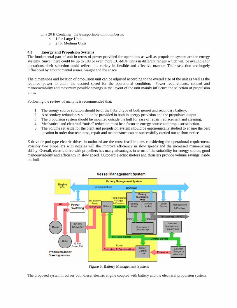
Figure 5: Battery Management System
The proposed system involves both die nd the electrical propulsion system. sel electric engine coupled with battery a
4.2 EU-MOP Battery Management System
o work in real time in rapidly changing charging and discharging controlled environment
buse ithin the battery chain e braking charges to be absorbed without
dication of ttery relative to a new battery
lated vessel systems g the cells
ange” as shown below
The Battery Management System (BMS) is much more demanding than at first envisaged It has to interface with anumber of other on board systems, it has tconditions, and it has to work in a harsh and un
• The functions of a BMS suitable for a hybrid vessel are as follows: • Monitoring the conditions of individual cells which make up the battery • Maintaining all the cells within their operating limits • Protecting the cells from out of tolerance conditions • Providing a "Fail Safe" mechanism in case of uncontrolled conditions or a• Compensating for any imbalances in cell parameters w• Setting the battery operating point to allow regenerativ
overcharging the battery • Providing information on the State of Charge (SOC) of the battery • Providing information on the State of Health (SOH) of the battery This measurement gives an in
the condition of a used ba• Providing information for driver displays and alarms • Predicting the range possible with the remaining charge in the battery • Accepting and implementing control instructions from re• Providing the optimum charging algorithm for chargin• Providing means of access for charging individual cells • Responding to changes in the vessel operating mode • Interact with the main diesel power plant to achieve the “Working R
Figure 6: Working range of Hybrid System
A BMS will need to cater for a variety of modes and circumstances albeit remotely operated. The Figure 5 is a conceptual representation of the p main BMS building blocks, the Battery Monitoring Unit (BMU), the Battery Control Unit BCU) and the CAN bus vessel communications network
rimary BMS functions which shows the three (
and how they interface with the rest of the energy management system Other configurations are possible with distributed BMS embedded in the battery cell to cell interconnections.
Proposed Propulsion system for Large Vessel
• 2 propellers @ 12.5kW each (150VDC) (note that this is 3 times higher the 48VDC voltage previously
e redundancy in design)
ngine failure one or both propellers operate, or Just one takes battery power (this gives options for
stated) • Both with steering capability (this giv
In the event of efail safe system)
Approximate Weight of Large Vessel Engine & Propulsion Systems The total weight of a typical 25kW genset is approximately 380kg dry (with an engine skid and cooling system
diators) – However in this application weight can be subtracted. The battery array has finally been reassessed as as the following characteristics as would be manufactured:
cial size possible at this moment for the required power. It should also be noted that the ncern. All this needs to be investigated ergonomically. A 47
a 25kW charging system. In order to manage this (and keeping weight very low), a andard 3ph industrial motor controller may well be employed. By reprogramming the system, it can act as a
which are working together to clean the oil spill their maneuvering char important to avoid collision, effective way of collecting and transporting recovered oil in up
2 m waves. Manouvering calculations for monocat EU-MOP unit have been carried out according to current IMO ed as:
for different loading conditions Course-keeping and directional stability analysis by taking into account the effects such as current, waves, wind
he table below. The nozzle deflection
or Case V it is seen that the transverse stability and roll damping characteristics of the unit is greatly reduced.
rah
• Endurance = 0.9h@25kW: • Battery size = 150VDC pack consisting of (197...118VDC) (arranged as 16 (15) x 3 cells) • Mass = 249.1kg • Dimensions = 1136mm x 546mm x 285 mm • Output = 22.6kWh
This is the lowest commerdimensions of the battery are bulky enough to cause cocell 150Ah pack will require stcharging system when supplying power by the 3ph side and charging the battery by linking them to the DC-Bus. Weight is approximately 30kg. A brake down of the relative masses involved is as follows:
4.3 Manouvering aspects As EU-MOP units are autonomous units,
acteristics are verytoCriteria. These calculations can be list Turning ability of the monocat units for different loading conditions & speeds. Initial turning ability assessment. Yaw checking ability within IMO criteria
and autopilot response. The cases used to assess the turning ability of the monocat units are given in tangle is set to the maximum value of 60°. FTherefore Case VI is calculated to determine the maximum in Nozzle Deflection angle to obtain an acceptable value of roll angle.
Case Load Speed(knots) STD Advance/Lpp Transfer/Lpp SRA TCM (sec) I Light 5 4.039 3.861 1.413 5.134 35.50 II Light 1 6.499 5.668 3.169 0.492 339.90 III Medium 5 4.671 4.305 1.867 4.678 43.40 IV M edium 2 6.558 5.692 3.225 0.111 175.90 V Full 5 4.273 3.942 1.651 15.000∗ 39.10 VI Full1 5 11.305 9.120 6.698 6.169 123.20
Table 1 Monocat Unit result or Turni le
he fu urn with ll no uthing units
should be reduced to accept sted with different loading conditions at 5 knots. Following Section 2.3.3, the criteria r the maximum first overshoot is 10° and the maximum
s f ng Circ
Figure 7: Effect of Nozzle Deflection Angle (NDA) on Turning Ability (Monocat)
lly loaded condition poses a serious reduction in transverse stability characteristics and therefore a tzzle deflection causes excessive roll angles. To avoid this the nozzle deflection angle of the azim
Figure 7: Effect of Nozzle deflection angle on turning circle
Tfu
able degrees. Yaw checking ability of the EUMOP units are te fo
second overshoot is 25° for 10°/10° Zig-Zag manoeuvre. The results are presented in the following table. Case Load Unit 1st Overshoot 2nd Overshoot III Light Monocat 4.251° 4.935° IV Medium Monocat 3.115° 3.081° V Full Monocat 3. 1° 3. 8° 50 56
Table 2: ig-Zag Man
e roll characteristic he units in the Z noeuvres ca interest from ity point of view and is presented as the maximum roll an
10°/10° Z oeuvre Results
Th s of t ig-Zag ma n be of operabil
gle encountered in the manoeuvre per case.
Effect of Nozzle Deflection Angle
16
18
-2
0
2
4
6
8
10
12
14
-8 -6 -4 -2 0 2 4 6 8 10 12
X/L
Y/L
Full (V - NDA 60)Full (VI - NDA 14)
Case Load Unit Manoeuvre Maximum Roll
V Light Monocat 10°/10° 2.660° VI Light Monocat 20°/20° 3.270° VII Medium Monocat 10°/10° 2.990° VIII M M t edium onoca 20°/20° 5.775° IX Full Monocat 10°/10° 10.997° X Full Monocat 20°/20° 16.746°
Table 5 Roll Angle d at Zig-Zag vres at Full S
Co
Maximum Encountere Manoeu peed
M ll
-15
-10
-5
0
5
10
15
0 2 4 6 8 10 12 14 16 18
Time (sec)
Yaw
, ND
A, R
oll (
degr
ee)
onocat FuYawNDARoll
Figure 8: 10/10 Zig-Zag Manoeuvre for fully loaded condition
urse-keeping and Directional Stability in Waves irectional stability characteristics of Monocat is investigated by taking into account the effect of environD ment such
as winds, local currents a es of freedom, while the propeller will be assumed as a Ka-4-70 propeller series i the Nozzle 19A. The P/D ratio is chosen as 16/13 as a
nd waves. Time domain simulations are made in six degren
Figure 10: Effect of Environment on Transit Speed (Monocat)
-15
-10
-5
0
5
10
15
0 10 20 30 40 50 60 70 80 90
Time (sec)
Rol
l (de
gree
)
100
Calm WaterWaves Waves & Wind
Figure 11: Roll Motion Response at Transit Speed
From the analysis performed above, it can be stated that the yaw checking ability of monocot unit is well within IMO requirements. As expected from the turning ability analysis, the monocat directional stability is better. However from an operational point of view, the amplitude of oscillation for this unit is not acceptable as the loading of the craft increases. An excessive pitch angle can be encountered at the transit speed. There are couple of areas that monocot fails to comply with IMO criteria, which is not a compulsory standard for these units. However, the challenge will be to eliminate these problems in the later stages of the design. Final Remarks The autonomous EU-Mop Monocat provides a good solution to challenging problems. At later stages, this initial design will be further improved by solving many remaining issues ranging from swarm operation to performance including collection of spilled oil and disposing it. As the aim is to deal with the small to medium size oil spills especially in shallow waters, the ultimate aim is to reduce the weight of the system continuously while decreasing the manufacturing cost of the system to very reasonable level so that they can be purchased and located almost everywhere to create an effective oil cleaning capability Europe-Wide. This paper provided enough challenges to industry to produce the EU-Mop unit parts lighter, durable and cheaper.
References 1. Psaraftis H.N., Tharakan G.G. “Optimal Response to Oil Spills: The Strategic Decision Case”, Operations
Research, 1986. 2. Psaraftis H.N., Ziogas B.O. “A Tactical Decision Algorithm for the Optimal Dispatching of Oil Spill Cleanup
Equipment”, Management Science, 1985. 3. Ventikos N.P. “Development of an Evaluation Model for the Importance, the Causes and the Consequences of
Oil Marine Pollution: the Case of Maritime Transport in the Greek Seas and in the Gulf of Saronikos”, PhD Thesis, NTUA, Athens, Greece, 2002.
4. Ventikos N.P., Zacharioudakis P., Volakis S., Lyridis D.V. (approved by H.N. Psaraftis) “Marine Safety Specification for the Aegean Sea”, Technical Report of the AEGEAN project, Athens, Greece, 2004.
5. O.Turan et al: Report on Task 2.2 First loop for preliminary design, EU-MOP Project, November 2000