Journal of Engineering Science and Technology Vol. 10, No.10 (2015) 1293 - 1309 © School of Engineering, Taylor’s University
1293
DESIGN AND OPTIMIZATION OF VALVELESS MICROPUMPS BY USING GENETIC ALGORITHMS APPROACH
AIDA F. M. SHUKUR1,*, NEOH S. CHIN
2, NORHAYATI S.
1, BIBI N. TAIB
1
1School of Microelectronic Engineering, Universiti Malaysia Perlis,
Kampus Alam Pauh Putra, 02600 Pauh, Perlis, Malaysia Computational Intelligence Research Group,
2Department of Computing Science and Digital Technologies,
Faculty of Engineering and Environment,
University of Northumbria, Newcastle NE1, 8ST, UK
*Corresponding Author: [email protected]
Abstract
This paper presents a design optimization of valveless micropump using
Genetic Algorithms (GA). The micropump is designed with a diaphragm,
pumping chamber and diffuser/nozzle element functions as inlet and outlet of
micropump with outer dimension of (5×1.75×5) mm3. The main objectives of
this research are to determine the optimum pressure to be applied at
micropump’s diaphragm and to find the optimum coupling parameters of the
micropump to achieve high flow rate with low power consumption. In order to
determine the micropump design performance, the total deformation, strain
energy density, equivalent stress for diaphragm, velocity and net flow rate of
micropump are investigated. An optimal resonant frequency range for the
diaphragm of valveless micropump is obtained through the result assessment. With the development of GA-ANSYS model, a maximum total displacement of
diaphragm, 5.3635 µm, with 12 kPa actuation pressure and optimum net
flowrate of 7.467 mL/min are achieved.
Keywords: Valveless micropumps, Optimization, Genetic algorithms (GA),
Fitness functions.
1. Introduction
In recent years, micropumps are important aspects of microelectromechanical
system (MEMS) and microfluidic component because of the ability to control
fluids transport in microscale [1-4]. Micropump has to control the flow of fluidic
accurately and efficiently. In contrast to other microfluidics devices, micropump
1294 A. F. M. Shukur et al.
Journal of Engineering Science and Technology October 2015, Vol. 10(10)
Nomenclatures
A Narrowest cross-section area of diffuser
E Young’s Modulus
F1 Fitness function for total deformation
F2 Fitness function for strain energy density
F3 Fitness function for equivalent stress
F4 Fitness function for resonant frequency
F5 Fitness function for flow rate
F6 Fitness function for velocity
Fm Fitness value for the specification m
Fmaverage Average value of specification m at Generation 1
P Distributed pressure
Pin Static pressure at inlet
Pout Static pressure at outlet
Pm Mutation probability
Px Crossover probability
Q Flow rate
R Diaphragm radius
t Diaphragm thickness
v Material’s Poisson Ratio
Vd/n Fluid velocity of diffuser or nozzle
Wm Weight for specification m
ymax Diaphragm displacement
Greek Symbols
ξd/n Pressure loss coefficient of diffuser or nozzle
ρ Fluid density
θ Diffuser angle
∆Pd/n Pin – Pout of diffuser or nozzle
Abbreviations
AI Artificial Intelligence
ANN Artificial Neural Network
CFD Computational Fluid Dynamic
EHD Electrohydrodynamic
FPW Flexural Planar Wave
GA Genetic Algorithms
ICPF Ionic Conductive Polymer Film
MEMS Microelectromechanical System
MHD Magnetohydrodynamic
SMA Shape Memory Alloy
is a component that has several operating principles and consists of various
actuation mechanisms according to its application.
The ideas of micropumps have been developed since 1980's by Smits et al.
[5]. Basically, there are three classes of micropump which are check-valve pump,
peristaltic pump and valveless pump. Check-valve micropumps are very sensitive
to bubbles and small particles whereas peristaltic pump requires periodic
replacement of flexible tubing. Besides, fatigue, wear and fragile are the critical
Design and Optimization of Valveless Micropumps by Using Genetic . . . . 1295
Journal of Engineering Science and Technology October 2015, Vol. 10(10)
problems that could decrease the micropump performance. In order to prevent
these issues, the valveless micropump is used in this research.
Valveless micropump consists of two fluid flow rectifying diffuser and nozzle
elements which are connected to the inlet and outlet of a pumping chamber with
an oscillating diaphragm. It does not use check-valve to rectify flow. A valveless
micropump was introduced by Stemme et al. [6-7] in 1993 using nozzle/diffuser
as flow rectifying elements. In 1997, Olsson et al. [8] proposed a valveless
diffuser micropump using silicon material. Such diffusers are used to affect flow
rectification and thus lead to pumping action in one preferential direction [9].
Generally, micropumps can be mechanical and non-mechanical according to the
actuation methods of the micropump. A mechanical micropump needs a physical
actuator or mechanism to perform pumping action such as electrostatic,
piezoelectric, thermopneumatic, shape memory alloy (SMA), bimetallic, ionic
conductive polymer film (ICPF), electromagnetic and phase change [1, 3, 10-12].
On the other hand, non-mechanical micropump needs to transform certain available
non-mechanical energy into kinetic momentum so that the fluid in microchannels
can be driven into the pumping chamber. The most popular non-mechanical
micropumps are magnetohydrodynamic (MHD), electrohydrodynamic (EHD),
electroosmotic, electrowetting, bubbletype, flexural planar wave (FPW),
electrochemical and evaporation based micropump [1, 3, 12-13].
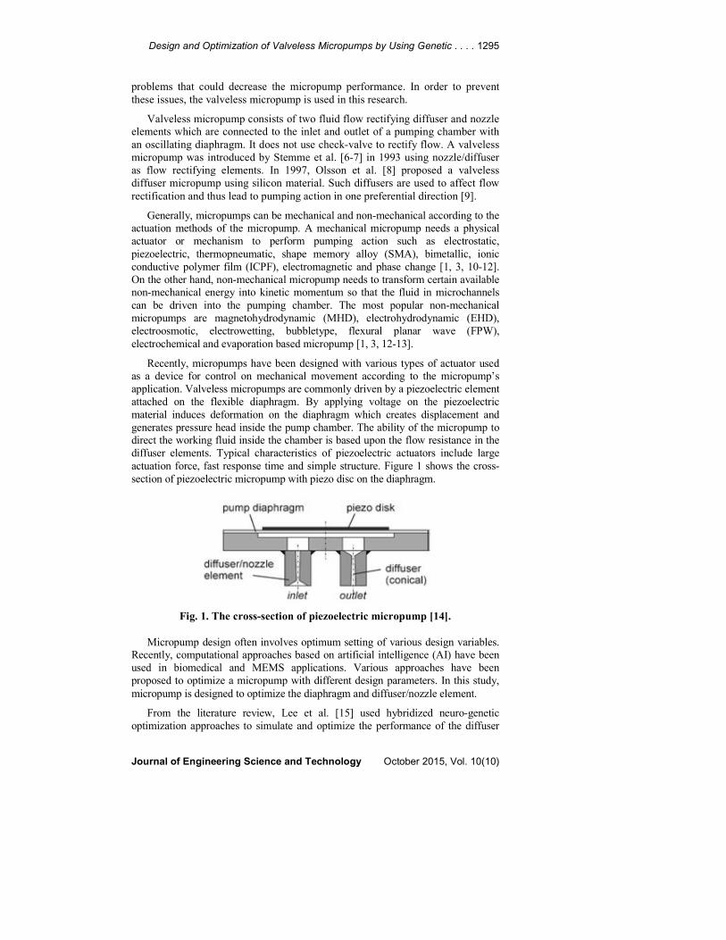
Recently, micropumps have been designed with various types of actuator used
as a device for control on mechanical movement according to the micropump’s
application. Valveless micropumps are commonly driven by a piezoelectric element
attached on the flexible diaphragm. By applying voltage on the piezoelectric
material induces deformation on the diaphragm which creates displacement and
generates pressure head inside the pump chamber. The ability of the micropump to
direct the working fluid inside the chamber is based upon the flow resistance in the
diffuser elements. Typical characteristics of piezoelectric actuators include large
actuation force, fast response time and simple structure. Figure 1 shows the cross-
section of piezoelectric micropump with piezo disc on the diaphragm.
Fig. 1. The cross-section of piezoelectric micropump [14].
Micropump design often involves optimum setting of various design variables.
Recently, computational approaches based on artificial intelligence (AI) have been
used in biomedical and MEMS applications. Various approaches have been
proposed to optimize a micropump with different design parameters. In this study,
micropump is designed to optimize the diaphragm and diffuser/nozzle element.
From the literature review, Lee et al. [15] used hybridized neuro-genetic
optimization approaches to simulate and optimize the performance of the diffuser
1296 A. F. M. Shukur et al.
Journal of Engineering Science and Technology October 2015, Vol. 10(10)
elements for applications in valveless diaphragm micropumps. In the research,
artificial neural network (ANN) has been trained as a fitness function into GA to
optimize the flow rectification efficiency of diffuser element. On the other hand,
Hidetoshi et al. [16] proposed GA for the optimization of thickness distribution of
micro-membrane. In their study, GA is used to reduce the search space for
optimizing the thickness distribution of a micro-membrane. In addition, from the
paper of Ravi et al. [17], GA is recommended as the optimization method to
optimize the geometrical parameters of peristaltic micropump to improve flow rate.
In this research, the GA technique is introduced to optimize the micropump
diaphragm and performance of the diffuser/nozzle elements. The GA is stochastic
in nature and has been widely accepted for its capability to obtain near optimum
solution without the requirements of complex mathematical formulation. Due to
the robustness of GA, this research develops a GA-ANSYS model to run the GA
optimization in conjunction with the ANSYS simulation system.
2. Research Motivation
This paper proposed the optimization of valveless micropump using GA. The
differences of this work with others are the parameters, structure, materials and
design of micropump to be optimized. Furthermore, the micropump structure is
designed and analyzed by using ANSYS and optimized by using MATLAB.
Table 1 shows the micropump optimization comparison. In 2009, Lee et al. [15]
proposed optimization of valveless micropump diffuser by using the combination of
ANN and GA. In 2011, Nikhil et al. [14] proposed optimization of valveless
micropump using a SIMULINK model based on its mathematical model. Based on
this study, the SIMULINK model is used to obtain diaphragm deflection,
volumetric discharge and pressure. The optimization of micropump is often critical.
Therefore, only certain optimization scopes like diaphragm or diffuser element are
focused in the previous micropump studies. In the optimization of micropump,
actuation pressure is a parameter of concern that will cause high power
consumption. From Table 1, the actuation pressure applied at micropump by [14] is
large. Considering the importance of many design parameters, the current research
study optimizes the diaphragm and diffuser of micropump simultaneously together
with actuation pressure, strain energy and stress of diaphragm.
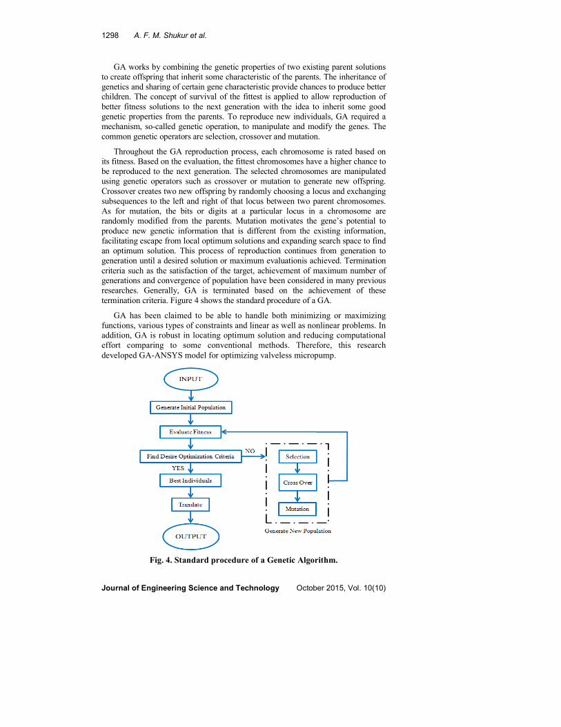
3. Working Principle
Working principle of micropump might be the most important to obtain the
performance behavior of micropump. The working principle of the
diffuser/nozzle elements in a valveless micropump is schematically shown in
Fig. 2. In the “supply mode”, the diaphragm moves vertically upwards increasing
the chamber volume and causes reduction in the chamber pressure. Pressure
difference between the pump chamber and inlet/outlet enables the fluid to flow
into the pump chamber from both the inlet and outlet. At this instance, fluid will
enter the pump chamber from the inlet through the diffuser direction while at the
outlet; fluid will enter through the diffuser element at the nozzle direction instead.
For the “pumping mode”, the reverse phenomenon occurs [14, 18-22].
Design and Optimization of Valveless Micropumps by Using Genetic . . . . 1297
Journal of Engineering Science and Technology October 2015, Vol. 10(10)
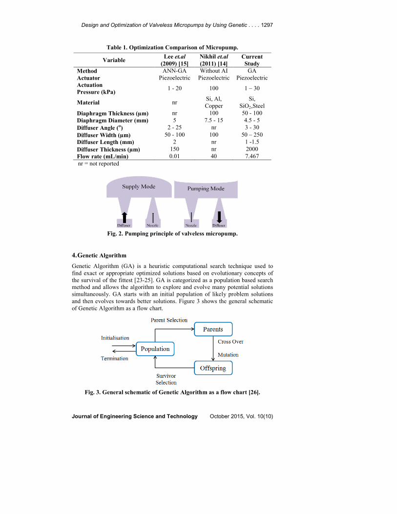
Table 1. Optimization Comparison of Micropump.
Variable Lee et.al
(2009) [15]
Nikhil et.al
(2011) [14]
Current
Study
Method ANN-GA Without AI GA
Actuator Piezoelectric Piezoelectric Piezoelectric
Actuation
Pressure (kPa) 1 - 20 100 1 – 30
Material nr Si, Al,
Copper
Si,
SiO2,Steel
Diaphragm Thickness (µm) nr 100 50 - 100
Diaphragm Diameter (mm) 5 7.5 - 15 4.5 - 5
Diffuser Angle (º) 2 - 25 nr 3 - 30
Diffuser Width (µm) 50 - 100 100 50 – 250
Diffuser Length (mm) 2 nr 1 -1.5
Diffuser Thickness (µm) 150 nr 2000
Flow rate (mL/min) 0.01 40 7.467
nr = not reported
Fig. 2. Pumping principle of valveless micropump.
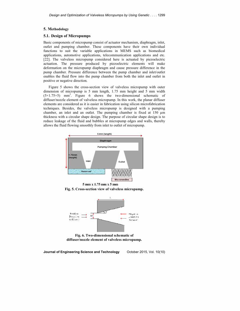
4. Genetic Algorithm
Genetic Algorithm (GA) is a heuristic computational search technique used to
find exact or appropriate optimized solutions based on evolutionary concepts of
the survival of the fittest [23-25]. GA is categorized as a population based search
method and allows the algorithm to explore and evolve many potential solutions
simultaneously. GA starts with an initial population of likely problem solutions
and then evolves towards better solutions. Figure 3 shows the general schematic
of Genetic Algorithm as a flow chart.
Fig. 3. General schematic of Genetic Algorithm as a flow chart [26].
1298 A. F. M. Shukur et al.
Journal of Engineering Science and Technology October 2015, Vol. 10(10)
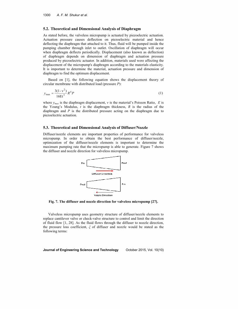
GA works by combining the genetic properties of two existing parent solutions
to create offspring that inherit some characteristic of the parents. The inheritance of
genetics and sharing of certain gene characteristic provide chances to produce better
children. The concept of survival of the fittest is applied to allow reproduction of
better fitness solutions to the next generation with the idea to inherit some good
genetic properties from the parents. To reproduce new individuals, GA required a
mechanism, so-called genetic operation, to manipulate and modify the genes. The
common genetic operators are selection, crossover and mutation.
Throughout the GA reproduction process, each chromosome is rated based on
its fitness. Based on the evaluation, the fittest chromosomes have a higher chance to
be reproduced to the next generation. The selected chromosomes are manipulated
using genetic operators such as crossover or mutation to generate new offspring.
Crossover creates two new offspring by randomly choosing a locus and exchanging
subsequences to the left and right of that locus between two parent chromosomes.
As for mutation, the bits or digits at a particular locus in a chromosome are
randomly modified from the parents. Mutation motivates the gene’s potential to
produce new genetic information that is different from the existing information,
facilitating escape from local optimum solutions and expanding search space to find
an optimum solution. This process of reproduction continues from generation to
generation until a desired solution or maximum evaluationis achieved. Termination
criteria such as the satisfaction of the target, achievement of maximum number of
generations and convergence of population have been considered in many previous
researches. Generally, GA is terminated based on the achievement of these
termination criteria. Figure 4 shows the standard procedure of a GA.
GA has been claimed to be able to handle both minimizing or maximizing
functions, various types of constraints and linear as well as nonlinear problems. In
addition, GA is robust in locating optimum solution and reducing computational
effort comparing to some conventional methods. Therefore, this research
developed GA-ANSYS model for optimizing valveless micropump.
Fig. 4. Standard procedure of a Genetic Algorithm.
Design and Optimization of Valveless Micropumps by Using Genetic . . . . 1299
Journal of Engineering Science and Technology October 2015, Vol. 10(10)
5. Methodology
5.1. Design of Micropumps
Basic components of micropump consist of actuator mechanism, diaphragm, inlet,
outlet and pumping chamber. These components have their own individual
functions to suit the variable applications in MEMS such as biomedical
applications, automotive applications, telecommunication applications and etc.
[22]. The valveless micropump considered here is actuated by piezoelectric
actuation. The pressure produced by piezoelectric elements will make
deformation on the micropump diaphragm and cause pressure difference in the
pump chamber. Pressure difference between the pump chamber and inlet/outlet
enables the fluid flow into the pump chamber from both the inlet and outlet in
positive or negative direction.
Figure 5 shows the cross-section view of valveless micropump with outer
dimension of micropump is 5 mm length, 1.75 mm height and 5 mm width
(5×1.75×5) mm3. Figure 6 shows the two-dimensional schematic of
diffuser/nozzle element of valveless micropump. In this work, the planar diffuser
elements are considered as it is easier in fabrication using silicon microfabrication
techniques. Besides, the valveless micropump is designed with a pumping
chamber, an inlet and an outlet. The pumping chamber is fixed at 150 µm
thickness with a circular shape design. The purpose of circular shape design is to
reduce leakage of the fluid and bubbles at micropump edges and walls, thereby
allows the fluid flowing smoothly from inlet to outlet of micropump.
Fig. 5. Cross-section view of valveless micropump.
Fig. 6. Two-dimensional schematic of
diffuser/nozzle element of valveless micropump.
1300 A. F. M. Shukur et al.
Journal of Engineering Science and Technology October 2015, Vol. 10(10)
5.2. Theoretical and Dimensional Analysis of Diaphragm
As stated before, the valveless micropump is actuated by piezoelectric actuation.
Actuation pressure causes deflection on piezoelectric material and hence
deflecting the diaphragm that attached to it. Thus, fluid will be pumped inside the
pumping chamber through inlet to outlet. Oscillation of diaphragm will occur
when diaphragm deflects periodically. Displacement (also known as deflection)
of diaphragm depends on dimension of diaphragm and actuation pressure
produced by piezoelectric actuator. In addition, materials used were affecting the
displacement of the micropump's diaphragm according to the materials elasticity.
It is important to determine the material, actuation pressure and dimension of
diaphragm to find the optimum displacement.
Based on [1], the following equation shows the displacement theory of
circular membrane with distributed load (pressure P):
PRy 4
3
2
max16Et
)v-3(1= (1)
where ymax is the diaphragm displacement, v is the material’s Poisson Ratio, E is
the Young’s Modulus, t is the diaphragm thickness, R is the radius of the
diaphragm and P is the distributed pressure acting on the diaphragm due to
piezoelectric actuation.
5.3. Theoretical and Dimensional Analysis of Diffuser/Nozzle
Diffuser/nozzle elements are important properties of performance for valveless
micropump. In order to obtain the best performance of diffuser/nozzle,
optimization of the diffuser/nozzle elements is important to determine the
maximum pumping rate that the micropump is able to generate. Figure 7 shows
the diffuser and nozzle direction for valveless micropump.
Fig. 7. The diffuser and nozzle direction for valveless micropump [27].
Valveless micropump uses geometry structure of diffuser/nozzle elements to
replace cantilever valve or check-valve structure to control and limit the direction
of fluid flow [1, 28]. As the fluid flows through the diffuser to nozzle direction,
the pressure loss coefficient, ξ of diffuser and nozzle would be stated as the
following terms:
Design and Optimization of Valveless Micropumps by Using Genetic . . . . 1301
Journal of Engineering Science and Technology October 2015, Vol. 10(10)
2
2
1ddd VP ρξ=∆ (2)
2
2
1nnn VP ρξ=∆ (3)
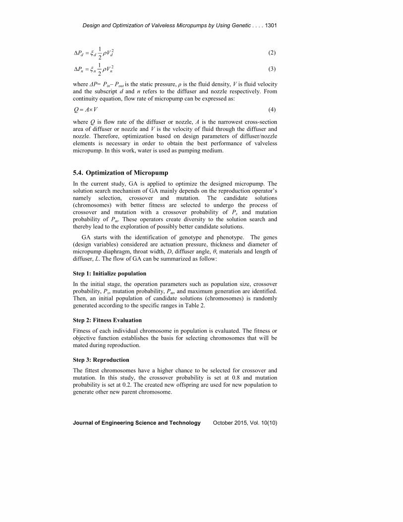
where ∆P= Pin– Pout is the static pressure, ρ is the fluid density, V is fluid velocity
and the subscript d and n refers to the diffuser and nozzle respectively. From
continuity equation, flow rate of micropump can be expressed as:
VAQ ×= (4)
where Q is flow rate of the diffuser or nozzle, A is the narrowest cross-section
area of diffuser or nozzle and V is the velocity of fluid through the diffuser and
nozzle. Therefore, optimization based on design parameters of diffuser/nozzle
elements is necessary in order to obtain the best performance of valveless
micropump. In this work, water is used as pumping medium.
5.4. Optimization of Micropump
In the current study, GA is applied to optimize the designed micropump. The
solution search mechanism of GA mainly depends on the reproduction operator’s
namely selection, crossover and mutation. The candidate solutions
(chromosomes) with better fitness are selected to undergo the process of
crossover and mutation with a crossover probability of Px and mutation
probability of Pm. These operators create diversity to the solution search and
thereby lead to the exploration of possibly better candidate solutions.
GA starts with the identification of genotype and phenotype. The genes
(design variables) considered are actuation pressure, thickness and diameter of
micropump diaphragm, throat width, D, diffuser angle, θ, materials and length of
diffuser, L. The flow of GA can be summarized as follow:
Step 1: Initialize population
In the initial stage, the operation parameters such as population size, crossover
probability, Px, mutation probability, Pm, and maximum generation are identified.
Then, an initial population of candidate solutions (chromosomes) is randomly
generated according to the specific ranges in Table 2.
Step 2: Fitness Evaluation
Fitness of each individual chromosome in population is evaluated. The fitness or
objective function establishes the basis for selecting chromosomes that will be
mated during reproduction.
Step 3: Reproduction
The fittest chromosomes have a higher chance to be selected for crossover and
mutation. In this study, the crossover probability is set at 0.8 and mutation
probability is set at 0.2. The created new offspring are used for new population to
generate other new parent chromosome.
1302 A. F. M. Shukur et al.
Journal of Engineering Science and Technology October 2015, Vol. 10(10)
Step 4: Repeat
Repeat Step 3 until the desired specifications of micropump are achieved
or maximum number of generation is met. The required specifications are listed
in Table 3.
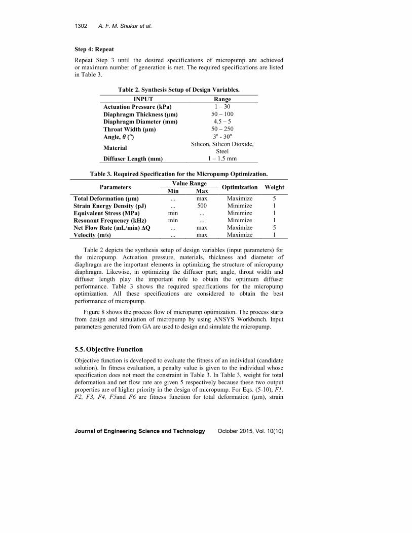
Table 2. Synthesis Setup of Design Variables.
INPUT Range
Actuation Pressure (kPa) 1 – 30
Diaphragm Thickness (µm) 50 – 100
Diaphragm Diameter (mm) 4.5 – 5
Throat Width (µm) 50 – 250
Angle, θ (º) 3º - 30º
Material Silicon, Silicon Dioxide,
Steel
Diffuser Length (mm) 1 – 1.5 mm
Table 3. Required Specification for the Micropump Optimization.
Parameters Value Range
Optimization Weight Min Max
Total Deformation (µm) ... max Maximize 5
Strain Energy Density (pJ) ... 500 Minimize 1
Equivalent Stress (MPa) min ... Minimize 1
Resonant Frequency (kHz) min ... Minimize 1
Net Flow Rate (mL/min) ∆Q ... max Maximize 5
Velocity (m/s) ... max Maximize 1
Table 2 depicts the synthesis setup of design variables (input parameters) for
the micropump. Actuation pressure, materials, thickness and diameter of
diaphragm are the important elements in optimizing the structure of micropump
diaphragm. Likewise, in optimizing the diffuser part; angle, throat width and
diffuser length play the important role to obtain the optimum diffuser
performance. Table 3 shows the required specifications for the micropump
optimization. All these specifications are considered to obtain the best
performance of micropump.
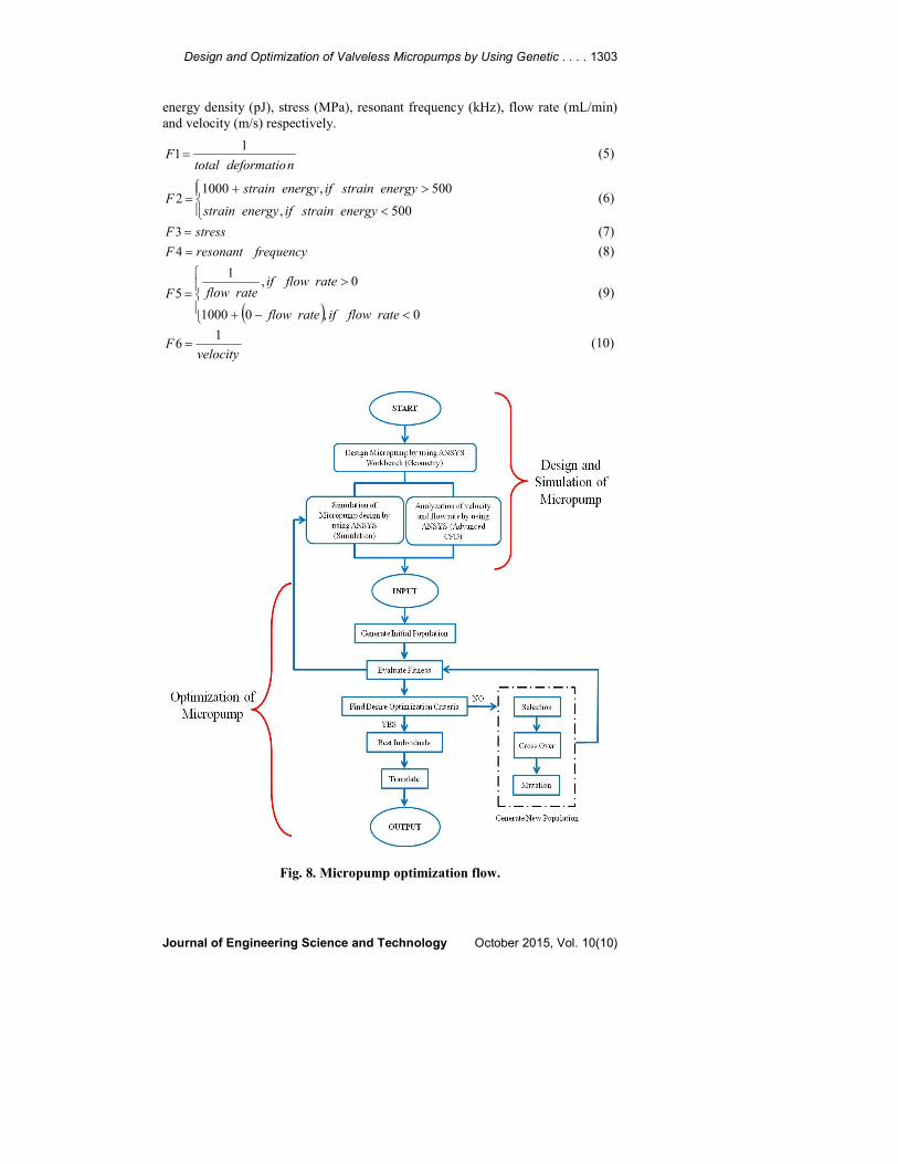
Figure 8 shows the process flow of micropump optimization. The process starts
from design and simulation of micropump by using ANSYS Workbench. Input
parameters generated from GA are used to design and simulate the micropump.
5.5. Objective Function
Objective function is developed to evaluate the fitness of an individual (candidate
solution). In fitness evaluation, a penalty value is given to the individual whose
specification does not meet the constraint in Table 3. In Table 3, weight for total
deformation and net flow rate are given 5 respectively because these two output
properties are of higher priority in the design of micropump. For Eqs. (5-10), F1,
F2, F3, F4, F5and F6 are fitness function for total deformation (µm), strain
Design and Optimization of Valveless Micropumps by Using Genetic . . . . 1303
Journal of Engineering Science and Technology October 2015, Vol. 10(10)
energy density (pJ), stress (MPa), resonant frequency (kHz), flow rate (mL/min)
and velocity (m/s) respectively.
ndeformatiototalF
11= (5)
<
>+=
500,
500,10002
energystrainifenergystrain
energystrainifenergystrainF (6)
stressF =3 (7)
frequencyresonantF =4 (8)
( )
<−+
>=
0,01000
0,1
5
rateflowifrateflow
rateflowifrateflowF (9)
velocityF
16 = (10)
Fig. 8. Micropump optimization flow.
1304 A. F. M. Shukur et al.
Journal of Engineering Science and Technology October 2015, Vol. 10(10)
After obtaining all the fitness from different specifications, an objective
normalization method used in [29] is applied to calculate the total objective value
for individual to prevent bias of fitness value due to different unit of
measurement. Equation (11) shows the calculation of total objective value by
dividing the fitness value of each specification function by the average value of
the specification.
∑ ==
z
mm
mmtot
averageF
FWF
1 (11)
where, Wm is the weight for specification m; Fm is the fitness value for the
specification m; Fmaverage is the average value of specification m at each
Generation 1. From Eq. (11) and the objective weight given in Table 3, the total
summation of all objective value, Ftot is derived in Eq. (12).
avgavgavgavgavgavgtot
F
F
F
F
F
F
F
F
F
F
F
FF
6
6
5
55
4
4
3
3
2
2
1
15 +++++= (12)
6. Result and Discussion
Based on the fitness of candidate solutions, GA evolves from generation to
generation to obtain better micropump design. Furthermore, GA optimizes the
design in a more systematic manner as compared to the conventional design that
is solely based on experiment and experience.
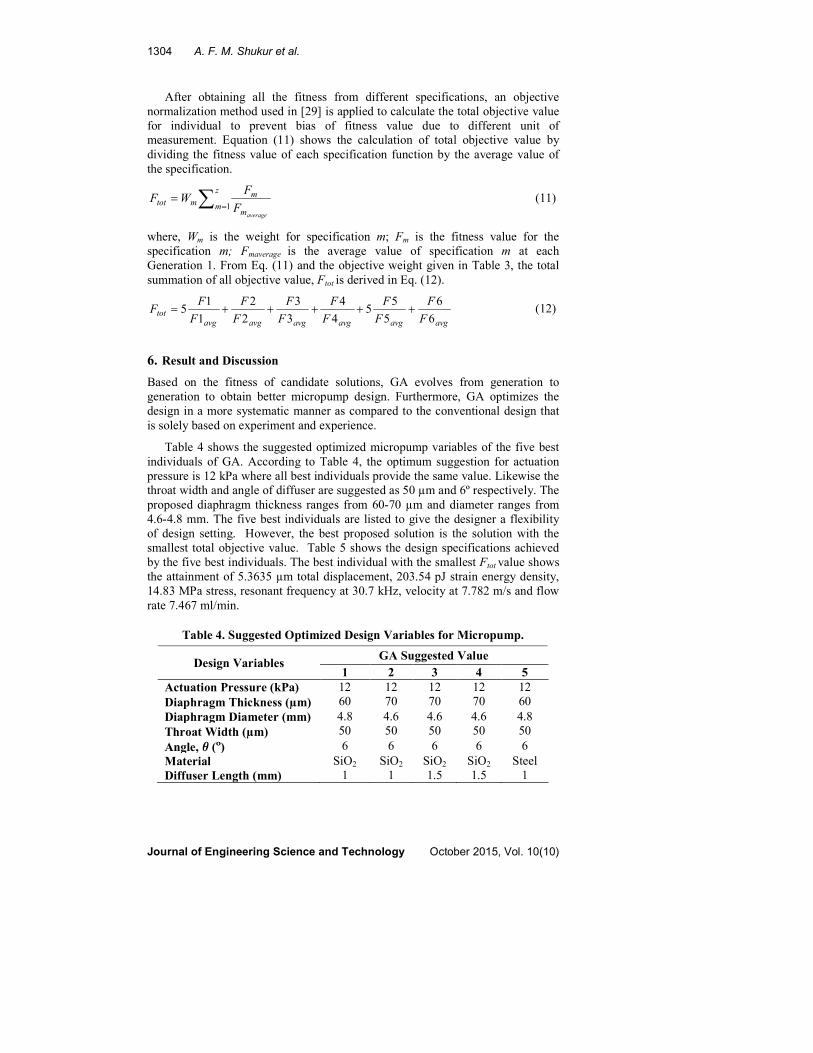
Table 4 shows the suggested optimized micropump variables of the five best
individuals of GA. According to Table 4, the optimum suggestion for actuation
pressure is 12 kPa where all best individuals provide the same value. Likewise the
throat width and angle of diffuser are suggested as 50 µm and 6º respectively. The
proposed diaphragm thickness ranges from 60-70 µm and diameter ranges from
4.6-4.8 mm. The five best individuals are listed to give the designer a flexibility
of design setting. However, the best proposed solution is the solution with the
smallest total objective value. Table 5 shows the design specifications achieved
by the five best individuals. The best individual with the smallest Ftot value shows
the attainment of 5.3635 µm total displacement, 203.54 pJ strain energy density,
14.83 MPa stress, resonant frequency at 30.7 kHz, velocity at 7.782 m/s and flow
rate 7.467 ml/min.
Table 4. Suggested Optimized Design Variables for Micropump.
Design Variables GA Suggested Value
1 2 3 4 5
Actuation Pressure (kPa) 12 12 12 12 12
Diaphragm Thickness (µm) 60 70 70 70 60
Diaphragm Diameter (mm) 4.8 4.6 4.6 4.6 4.8
Throat Width (µm) 50 50 50 50 50
Angle, θ (º) 6 6 6 6 6
Material SiO2 SiO2 SiO2 SiO2 Steel
Diffuser Length (mm) 1 1 1.5 1.5 1
Design and Optimization of Valveless Micropumps by Using Genetic . . . . 1305
Journal of Engineering Science and Technology October 2015, Vol. 10(10)
Table 5. Value of the Best Individual Chromosome.
Parameters Value Range
1 2 3 4 5
Total Deformation (µm) 5.3635 2.6996 2.6996 2.6996 1.8997
Strain Energy Density (pJ) 203.54 130.57 130.57 130.57 71.32
Equivalent Stress (MPa) 14.83 8.93 8.93 8.93 14.76
Resonant Frequency (kHz) 30.7 30.7 30.7 30.7 20.8
Velocity (m/s) 7.782 7.782 7.782 5.217 7.782
Net Flow Rate (mL/min)
∆Q
7.467 7.467 1.184 1.184 7.467
Total Objective Value 3.4859 3.4898 3.7233 3.7318 3.7732
According to Lee et al. [15], the net flow rate is around 0.01 mL/min at 10 kPa
actuation pressure with angle of diffuser is 8º. Cui et al. [10] found that maximum
displacement of pump diaphragm is around 0.7 µm at 140 V excitation voltage.
This work claims that, higher excitation voltage gives the better result in diaphragm
displacement. So the higher voltage gives a significant effect to the higher power
consumption. In current study, actuation pressure is a parameter of concern that will
cause high power consumption. The lower the actuation pressure lowers the power
consumption. Based on Podder et al. [30], the best pump performance is achieved
by having an excitation frequency which is close to the pump resonant frequency.
The resonant frequency of the micropump is governed by the mass of the fluid in
the diffuser/nozzle element and the elastic properties of the pump diaphragm [30].
This current study set the response frequency within 1 – 100 kHz. So, the lower the
resonant frequency gives better result in pump performance.
In this work, the strain energy and stress of the diaphragm are considered
because these two specifications are important elements in mechanical analysis.
Theoretically, strain energy is the energy stored in a body due to deformation and
stress is force per unit area. Strain energy and stress are closely related in
mechanical analysis. Under small deformation, strain and stress terms are directly
proportional to each other according to Hooke’s law [31]. It has been discovered
that the equivalent stress in five optimum individuals is under 15 MPa (refer to
Table 5), while the Young Modulus, E of silicon dioxide, SiO2 is 73 GPa. So, the
stress level is certainly below the yield strength of the materials. This study also
tested the effect of materials towards the micropump performance. The material
chosen is needed to absorb enough pressure without failure. In this work, silicon,
steel and silicon dioxide are tested. The optimum material chosen by GA is
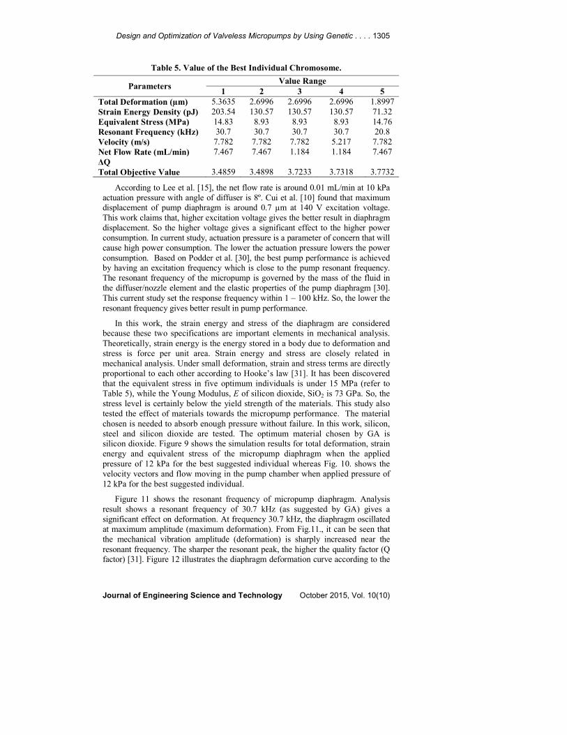
silicon dioxide. Figure 9 shows the simulation results for total deformation, strain
energy and equivalent stress of the micropump diaphragm when the applied
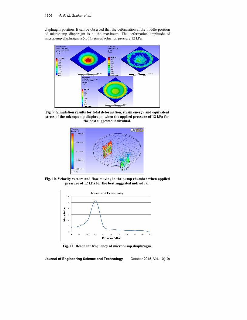
pressure of 12 kPa for the best suggested individual whereas Fig. 10. shows the
velocity vectors and flow moving in the pump chamber when applied pressure of
12 kPa for the best suggested individual.
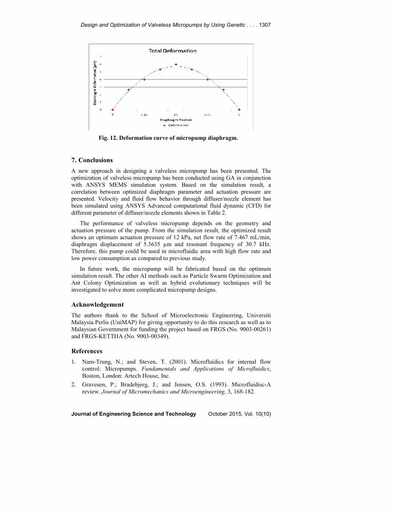
Figure 11 shows the resonant frequency of micropump diaphragm. Analysis
result shows a resonant frequency of 30.7 kHz (as suggested by GA) gives a
significant effect on deformation. At frequency 30.7 kHz, the diaphragm oscillated
at maximum amplitude (maximum deformation). From Fig.11., it can be seen that
the mechanical vibration amplitude (deformation) is sharply increased near the
resonant frequency. The sharper the resonant peak, the higher the quality factor (Q
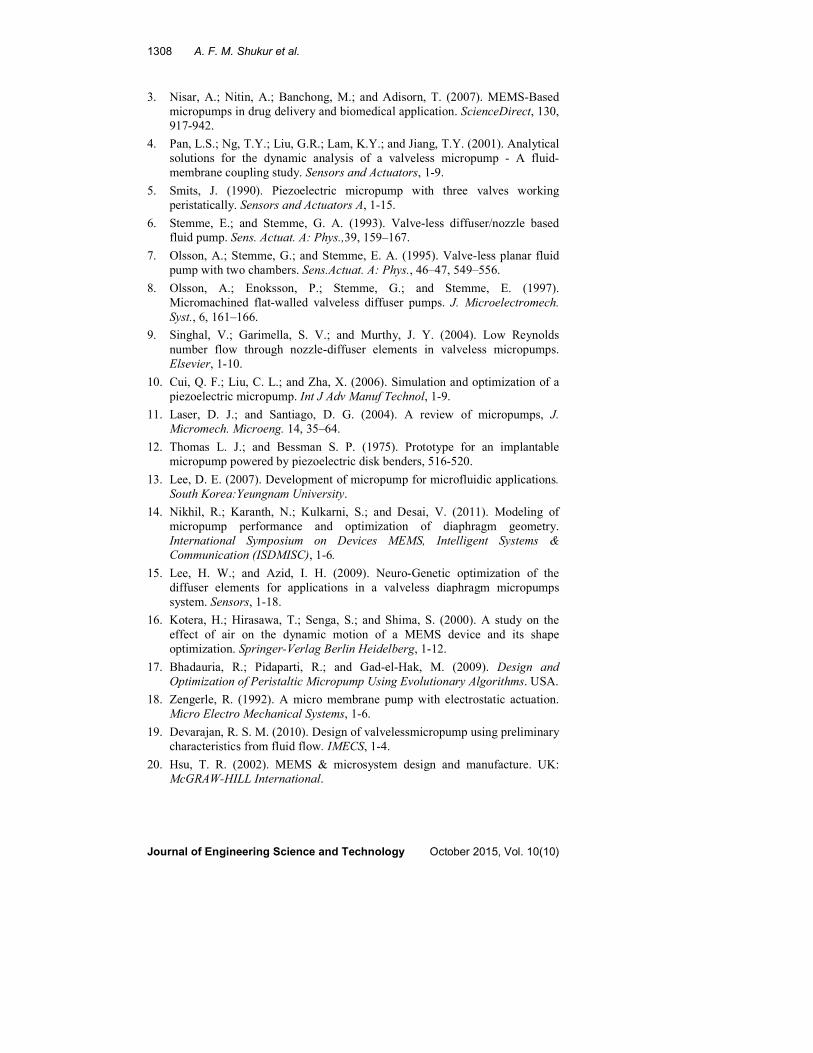
factor) [31]. Figure 12 illustrates the diaphragm deformation curve according to the
1306 A. F. M. Shukur et al.
Journal of Engineering Science and Technology October 2015, Vol. 10(10)
diaphragm position. It can be observed that the deformation at the middle position
of micropump diaphragm is at the maximum. The deformation amplitude of
micropump diaphragm is 5.3635 µm at actuation pressure 12 kPa.
Fig. 9. Simulation results for total deformation, strain energy and equivalent
stress of the micropump diaphragm when the applied pressure of 12 kPa for
the best suggested individual.
Fig. 10. Velocity vectors and flow moving in the pump chamber when applied
pressure of 12 kPa for the best suggested individual.
Fig. 11. Resonant frequency of micropump diaphragm.
Design and Optimization of Valveless Micropumps by Using Genetic . . . . 1307
Journal of Engineering Science and Technology October 2015, Vol. 10(10)
Fig. 12. Deformation curve of micropump diaphragm.
7. Conclusions
A new approach in designing a valveless micropump has been presented. The
optimization of valveless micropump has been conducted using GA in conjunction
with ANSYS MEMS simulation system. Based on the simulation result, a
correlation between optimized diaphragm parameter and actuation pressure are
presented. Velocity and fluid flow behavior through diffuser/nozzle element has
been simulated using ANSYS Advanced computational fluid dynamic (CFD) for
different parameter of diffuser/nozzle elements shown in Table 2.
The performance of valveless micropump depends on the geometry and
actuation pressure of the pump. From the simulation result, the optimized result
shows an optimum actuation pressure of 12 kPa, net flow rate of 7.467 mL/min,
diaphragm displacement of 5.3635 µm and resonant frequency of 30.7 kHz.
Therefore, this pump could be used in microfluidic area with high flow rate and
low power consumption as compared to previous study.
In future work, the micropump will be fabricated based on the optimum
simulation result. The other AI methods such as Particle Swarm Optimization and
Ant Colony Optimization as well as hybrid evolutionary techniques will be
investigated to solve more complicated micropump designs.
Acknowledgement
The authors thank to the School of Microelectronic Engineering, Universiti
Malaysia Perlis (UniMAP) for giving opportunity to do this research as well as to
Malaysian Government for funding the project based on FRGS (No. 9003-00261)
and FRGS-KETTHA (No. 9003-00349).
References
1. Nam-Trung, N.; and Steven, T. (2001). Microfluidics for internal flow
control: Micropumps. Fundamentals and Applications of Microfluidics,
Boston, London: Artech House, Inc.
2. Gravesen, P.; Bradebjerg, J.; and Jensen, O.S. (1993). Microfluidisc-A
review. Journal of Micromechanics and Microengineering, 3, 168-182.
1308 A. F. M. Shukur et al.
Journal of Engineering Science and Technology October 2015, Vol. 10(10)
3. Nisar, A.; Nitin, A.; Banchong, M.; and Adisorn, T. (2007). MEMS-Based
micropumps in drug delivery and biomedical application. ScienceDirect, 130,
917-942.
4. Pan, L.S.; Ng, T.Y.; Liu, G.R.; Lam, K.Y.; and Jiang, T.Y. (2001). Analytical
solutions for the dynamic analysis of a valveless micropump - A fluid-
membrane coupling study. Sensors and Actuators, 1-9.
5. Smits, J. (1990). Piezoelectric micropump with three valves working
peristatically. Sensors and Actuators A, 1-15.
6. Stemme, E.; and Stemme, G. A. (1993). Valve-less diffuser/nozzle based
fluid pump. Sens. Actuat. A: Phys.,39, 159–167.
7. Olsson, A.; Stemme, G.; and Stemme, E. A. (1995). Valve-less planar fluid
pump with two chambers. Sens.Actuat. A: Phys., 46–47, 549–556.
8. Olsson, A.; Enoksson, P.; Stemme, G.; and Stemme, E. (1997).
Micromachined flat-walled valveless diffuser pumps. J. Microelectromech.
Syst., 6, 161–166.
9. Singhal, V.; Garimella, S. V.; and Murthy, J. Y. (2004). Low Reynolds
number flow through nozzle-diffuser elements in valveless micropumps.
Elsevier, 1-10.
10. Cui, Q. F.; Liu, C. L.; and Zha, X. (2006). Simulation and optimization of a
piezoelectric micropump. Int J Adv Manuf Technol, 1-9.
11. Laser, D. J.; and Santiago, D. G. (2004). A review of micropumps, J.
Micromech. Microeng. 14, 35–64.
12. Thomas L. J.; and Bessman S. P. (1975). Prototype for an implantable
micropump powered by piezoelectric disk benders, 516-520.
13. Lee, D. E. (2007). Development of micropump for microfluidic applications.
South Korea:Yeungnam University.
14. Nikhil, R.; Karanth, N.; Kulkarni, S.; and Desai, V. (2011). Modeling of
micropump performance and optimization of diaphragm geometry.
International Symposium on Devices MEMS, Intelligent Systems &
Communication (ISDMISC), 1-6.
15. Lee, H. W.; and Azid, I. H. (2009). Neuro-Genetic optimization of the
diffuser elements for applications in a valveless diaphragm micropumps
system. Sensors, 1-18.
16. Kotera, H.; Hirasawa, T.; Senga, S.; and Shima, S. (2000). A study on the
effect of air on the dynamic motion of a MEMS device and its shape
optimization. Springer-Verlag Berlin Heidelberg, 1-12.
17. Bhadauria, R.; Pidaparti, R.; and Gad-el-Hak, M. (2009). Design and
Optimization of Peristaltic Micropump Using Evolutionary Algorithms. USA.
18. Zengerle, R. (1992). A micro membrane pump with electrostatic actuation.
Micro Electro Mechanical Systems, 1-6.
19. Devarajan, R. S. M. (2010). Design of valvelessmicropump using preliminary
characteristics from fluid flow. IMECS, 1-4.
20. Hsu, T. R. (2002). MEMS & microsystem design and manufacture. UK:
McGRAW-HILL International.
Design and Optimization of Valveless Micropumps by Using Genetic . . . . 1309
Journal of Engineering Science and Technology October 2015, Vol. 10(10)
21. Ashraf, M. W.; Tayyaba, S.; and Afzulpurkar, N. (2011). Micro
electromechanical systems (MEMS) based microfluidic devices for
biomedical applications. International Journal of Molecular Sciences, 1-57.
22. Shukur, A. F. M. (2012). Design and analysis of MEMS based micropumps
for medical application. IMiEJS, 1-8.
23. Anguraj, S. K. K. (2010). A structured system of embedded based on
artificial intelligence by incorporating genetic algorithm. ICCCT’10, 1-4.
24. Zamani, M.; Taherdoost, H.; Manaf, A. A.; Ahamed, R.; and Zeki, M. A.
(2009). An artificial-intelligence-based approach for audio steganography.
Journal of Open Problems in Science and Engineering.
25. Varma, A.; and Erhardt, N. (1997). Genetic Algorithms. Retrieved 2012,
from Artificial Intelligences: http://biology.kenyon.edu/slonc/bio3/AI/GEN
_ALGO/gen_algo.html.
26. Chakraborty, R. (2010). Fundamentals of Genetic Algorithms. Retrieved Feb
2011, from RC Chakraborty, www.myreaders.info:www.myreaders.info/
html/artificial_intelligence.html.
27. Ahmadian, M. T.; Mehrabian, A. (2006). Design optimization by numerical
characterization of fluid flow through the valveless diffuser micropumps.
Journal of Physics: Conference Series, 34, 379-384.
28. Yang, H.; Tsai, T.-H.; and Hu, C.-C. (2008). Portable valve-less peristaltic
micropump design and fabrication. DTIP of MEMS & MOEMS, 1-6.
29. Chin, N. S.; Marzuki, A.; Morad, N.; Peng, L. C.; and Abdul Aziz, Z. (2008).
An interactive genetic algorithm approach to MMIC low noise amplifier
design using a layered encoding structure. IEEE, 1-5.
30. Podder, P. K.; Samajdar, D. P.; Mallick, D.; and Bhattacharyya, A. (2012).
Design and simulation of micro-pump, micro-valve and micro-needle for
biomedical applications. 2012 5th International Conference on Computers
and Devices for Communication (CODEC), 1-4.
31. Liu, C. (2006). Review of essential electrical and mechanical concepts.
Foundations of MEMS, USA: Pearson Education, Inc.


![Copyright · Jamil, Mohammad, Qatar University, Qatar ... Iman Shahosseini, ... et al. developed a valveless micropump [3], in which](https://static.documents.pub/doc/80x56/5b697af67f8b9adc178e71f3/-jamil-mohammad-qatar-university-qatar-iman-shahosseini-et-al-developed.jpg)


![JOURNAL OF MICROELECTROMECHANICAL SYSTEMS ...microfluidics.stanford.edu/Publications/Micropumps...0.05% versus 0.2% for glass pumps with 1.1 m diameter pores) [15]. Yao and Santiago](https://static.documents.pub/doc/80x56/5ff90d02348f111009060a08/journal-of-microelectromechanical-systems-005-versus-02-for-glass-pumps.jpg)


