Page 1
DESIGN AND TEST OF VEGETABLE OIL IMPREGNATED
POLYPROPYLENE FILM CAPACITORS
MR. BOONCHOO SOMBOONPEN
A THESIS SUBMITTED IN PARTIAL FULFILLMENT OF THE REQUIREMENTS
FOR THE DEGREE OF MASTER OF SCIENCE
IN ELECTRICAL POWER ENGINEERING
SIRINDHORN INTERNATIONAL THAI-GERMAN GRADUATE SCHOOL OF ENGINEERING
(TGGS)
GRADUATE COLLEGE
KING MONGKUT'S UNIVERSITY OF TECHNOLOGY NORTH BANGKOK
ACADEMIC YEAR 2007
COPYRIGHT OF KING MONGKUT'S UNIVERSITY OF TECHNOLOGY NORTH BANGKOK
Page 2
ii
Name : Mr.Boonchoo Somboonpen
Thesis Title : Design and Test of Vegetable Oil Impregnated Polypropylene
Film Capacitors
Major Field : Electrical Power Engineering
King Mongkut’s University of Technology North Bangkok
Thesis Advisor : Assistant Professor Dr.Teratam Bunyagul
Co-Advisor : Dr.Thanapong Suwanasri
Academic Year : 2007
Abstract
The principal objective of the thesis is to do about a feasibility study about the
manufacturing of the polypropylene film capacitors impregnated with three different
types of fluid. The types of fluid are sunflower oil, soybean oil and Envirotemp FR3
fluid. Sunflower oil and soybean oil were filtrated by a small experimental purifier.
The electrical attributes of both oils is qualified according to the fluid insulation
standards (ASTM D6871). The design of model capacitors is single-element with 1.9
microfarad capacitance and AC voltage at 1500 volt. The dielectric used in capacitor
element is double-layered, double-side rough type polypropylene film wounding
together and then flattened. Two capacitor elements were pressed, in order to have
distinct space factor, and packed together in a model tank capacitor. Each model
capacitor of each liquid dielectric was impregnated at four different treated levels of
temperature. From the comparison capacitor characteristic of test results in
accordance with IEC 60871-1 standard, it was found that the space factor, the
temperature level during impregnation, and the vegetable oil type affected to the
capacitance and dissipation factors in capacitor.
(Total 101 pages)
Keywords : Vegetable oil, Impregnating temperature, Space factor,
Polypropylene film capacitor
______________________________________________________________ Advisor
Page 3
iii
ช่ือ : นายบุญชู สมบุญเพ็ญ ช่ือวิทยานพินธ : ออกแบบและทดสอบตัวเกบ็ประจุโพลีโพรไพลีนแบบใช น้ํามันพืชแชอ่ิม สาขาวิชา : วิศวกรรมไฟฟากําลัง มหาวิทยาลัยเทคโนโลยีพระจอมเกลาพระนครเหนือ อาจารยที่ปรึกษาวิทยานิพนธหลัก : ผูชวยศาสตราจารย ดร.ธีรธรรม บุณยะกุล อาจารยที่ปรึกษาวิทยานิพนธรวม : อาจารย ดร.ธนพงษ สุวรรณศรี ปการศึกษา : 2550
บทคัดยอ
งานวิจยันี้เปนการศึกษากระบวนการผลิต ตัวเก็บประจุโพลีโพรไพลีนแบบแชอ่ิมในฉนวนน้ํามันพืช 3 ชนิด คือน้ํามันทานตะวัน น้าํมันถ่ัวเหลือง และฉนวนไฟฟาเหลวที่ผลิตจากน้ํามนัพืช
(Envirotemp FR3 Fluid) โดยทําการกรองน้ํามันทานตะวนั และน้ํามันถ่ัวเหลืองให ดวยเครื่องกรองน้ํามันฉนวนไฟฟาขนาดเล็กที่สรางขึ้น ผลการทดสอบคุณสมบัติทางฉนวนไฟฟาของน้ํามนัพืชทั้งสองชนิดไดคาตามมาตรฐานของฉนวนเหลว (ASTM D6871) การออกแบบตัวเก็บประจุเปนแบบตวัเดยีว มีคาความจุ 1.9 ไมโครฟาราด คาพิกดัแรงดันไฟฟากระแสสลับ 1,500 โวลทใชแผนฟลมโพลีโพรไพลีนแบบมีความขรุขระสองดาน สองช้ันเปนไดอิเล็กตริก สรางแบบพันมวนและบีบแบน มีขั้วตอแบบยืน่ออกสลับดานกัน บรรจุในถัง ถังละ 2 ตัว แตละตัวถูกบีบใหมีคาตัวประกอบชองวางตางกนั กระบวนการแชอ่ิมใชวิธีการดดูอากาศออกแลวเติมน้ํามันทีม่ีความบริสุทธิ์ ดวยความแตกตางของอุณหภูมิ 4 ระดับ
ผลการทดสอบและเปรียบเทียบคุณลักษณะของตวัเก็บประจุ ตามมาตรฐาน IEC 60871-1
ระหวางตัวเกบ็ประจุที่ใชฉนวนน้ํามันพืชแชอ่ิมทั้งสามชนิด พบวาตัวประกอบชองวาง อุณหภมูิของน้ํามันขณะแชอ่ิม และชนิดของน้ํามัน มีผลตอความเปลี่ยนแปลงคาความจุไฟฟา และคาตัวประกอบกําลังไฟฟาสูญเสียในไดอิเล็กตริกของตัวเก็บประจ ุ
(วิทยานพินธมีจํานวนทั้งสิ้น 101 หนา) คําสําคัญ : น้ํามันพืช,อุณหภูมิขณะแชอ่ิม,ตัวประกอบชองวาง,ตัวเกบ็ประจุแบบโพลีโพรไพลีน
_____________________________________________อาจารยที่ปรึกษาวิทยานิพนธหลัก
Page 4
iv
ACKNOWLEDGEMENTS
I would like to express the profound and sincere gratitude to my advisors,
Assistant Professor Dr.Teratam Bunyagul and Dr.Thanapong Suwannasri, for the
invaluable information about the step-by-step design and in-depth testing process of
vegetable oil impregnated polypropylene film capacitors which is the crucial subject
of this dissertation. This work would not have been possible without the support,
which also brought about my improvement and advancement of scientific knowledge,
particularly in the area of an empirical investigation and experimentation.
I owe my most honest thankfulness to Assistant Professor Sarawut Kleesuwan,
for his on structive comments and useful solutions to this study, including vegetable
oil purification system, the methodology in dielectric test and the impregnation
process of capacitors, the investigation of their characteristics, and above of all that
matter, his cordial encouragement when in time of difficulty.
In addition, I would like to state my appreciation officially to the Electrical
Engineering Department, Pathumwan Institute of Technology, for all materials and
equipments provided. I am deeply grateful to Nissin Electric (Thailand) Co., Ltd., for
the production of model capacitors which consists of the support on raw materials,
winding process the capacitor’s element, especially Mr. Pravich Prachumthes, for
advice capacitor impregnation process. I am also considerably indebted to Tusco
Trafo Co., Ltd., Tira Thai Co., Ltd., and High Voltage Laboratory, Transmission Line
Maintenance Division, Electricity Generating Authority of Thailand (EGAT) for their
supports on specific instruments for dielectric test and the measurement of the
dissipation factor in vegetable oil and model capacitors applied in this study.
Boonchoo Somboonpen
Page 5
v
TABLE OF CONTENTS
Page
Abstract (in English) ii
Abstract (in Thai) iii
Acknowledgements iv
List of Tables vii
List of Figures ix
Chapter 1 Introduction 1
1.1 High voltage capacitor 1
1.2 Oil impregnated polypropylene film capacitor 2
1.3 Vegetable oil in power capacitor 3
1.4 Vegetable oils 4
1.5 Purpose of the study 8
1.6 Scope of the study 8
1.7 Methods 9
1.8 Tools 9
1.9 Utilization of the study 9
1.10 The structure of thesis 10
Chapter 2 Material property in high voltage capacitor 11
2.1 Previous work on power capacitor 11
2.2 Dielectric materials 18
2.3 Liquid dielectric 22
2.4 Insulating oil purification system 26
2.5 Polypropylene dielectric 27
2.6 Composite dielectric 30
2.7 Wound capacitor flat winding 34
2.8 Capacitor impregnation process 41
2.9 Standard test method of capacitor (IEC 60871-1) 43
Chapter 3 Design and test of impregnated capacitor 45
3.1 Vegetable oil purification system 45
3.2 Vegetable oil properties 49
3.3 Design of capacitor element 54
Page 6
vi
TABLE OF CONTENTS (CONTINUED)
Page
3.4 Correction factor of capacitance for the reference temperature 60
3.5 Assembly of model capacitor 62
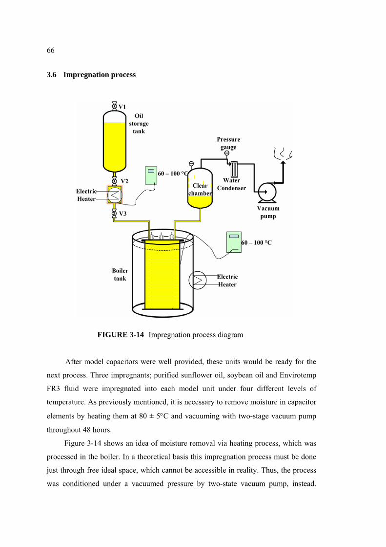
3.6 Impregnation process 66
3.7 Experimental test 68
Chapter 4 Testing of the capacitors 75
4.1 Capacitance of capacitors 75
4.2 Voltage test between terminals, and between terminals and
container 86
4.3 Dissipation factor of capacitor 87
4.4 Short circuit discharge test 92
Chapter 5 Conclusion and recommendations 95
5.1 Conclusion 95
5.2 Recommendations for further work 97
References 99
Biography 101
Page 7
vii
LIST OF TABLES
Table page
1-1 Envirotemp FR 3 fluid Values, and specification limits for
natural ester fluid and mineral oil 7
1-2 Typical initial Envirotemp FR3 fluid properties 8
2-1 Dielectric properties of some liquid dielectrics 25
2-2 Physical, chemical and thermal properties of polypropylene film 28
2-3 Electrical properties of polypropylene film 28
2-4 Dimension properties of polypropylene film 29
2-5 Space factor of polypropylene film 29
2-6 Electric withstanding capability of BOPP film 36
3-1 Vegetable oil properties from test results compared with natural
ester fluid standard and synthesis aster fluid for capacitor application 49
3-2 Relative permittivities of vegetable oils subjected to temperature
level as per IEC 60247 standard 51
3-3 Dissipation factors of vegetable oils subjected to
temperature level as per IEC 60247 standard 53
3-4 Correction factor of capacitance for 20 °C reference temperature 61
4-1 Capacitances of model units at the element thickness of 9.0 mm,
with rated capacitance of a capacitor designed at 1.9 µF at 30 °C 75
4-2 Capacitances of model units at the element thickness of 9.4 mm,
with rated capacitance of a capacitor designed at 1.9 µF at 30 °C 76
4-3 Capacitance of Sunflower oil impregnated polypropylene film capacitor
on surrounding temperature 77
4-4 Capacitance of soybean oil impregnated polypropylene film capacitor
on surrounding temperature 78
4-5 Capacitance of Envirotemp FR3 Fluid impregnated polypropylene film
capacitor on surrounding temperature 79
4-6 Capacitances of sunflower oil impregnated model capacitors at four
different impregnating temperatures 82
Page 8
viii
LIST OF TABLES (CONTINUED)
Table page
4-7 Capacitance of soybean oil impregnated model capacitors at four
different impregnating temperatures 83
4-8 Capacitances of Envirotemp FR3 fluid impregnated model capacitors
at four different impregnating temperatures 84
4-9 Dissipation factors of sunflower oil impregnated model capacitors
at four different impregnating temperatures 87
4-10 Dissipation factors of soybean oil impregnated model capacitors
at four different impregnating temperatures 88
4-11 Dissipation factors of Envirotemp FR3 fluid impregnated model
capacitors at four different impregnating temperatures 89
4-12 Summary of changes in capacitance of model capacitors impregnated
with three fluids at four different impregnating temperatures 92
Page 9
ix
LIST OF FIGURES
Figure page
1-1 Comparison of dietary fats 4
2-1 Insulating oil purification system 26
2-2 Capacitor comprising two layers of different dielectric materials 32
2-3 Capacitor Element of flattened wound capacitor 34
2-4 Two layer PP film wound capacitor 38
2-5 PP film and Al. foil of element capacitor wound type 38
2-6 Dimension of flattened type element wound capacitor 40
3-1 Small vegetable oil purification diagram 47
3-2 Small vegetable oil purification system 48
3-3 Dielectric breakdown voltage test of vegetable oils 50
3-4 Measurement of relative permittivity and dielectric dissipation factor 50
3-5 Dielectric breakdown voltages of vegetable oils 51
3-6 Relative permittivities of vegetable oils in temperature 52
3-7 Dissipation factors of vegetable oils 53
3-8 Rolling of capacitor element 55
3-9 Capacitor element 59
3-10 Model capacitor 62
3-11 Element pressing diagram 63
3-12 Capacitor element pressing process 64
3-13 Insert element to model capacitor 65
3-14 Impregnation process diagram 66
3-15 Impregnation process system 67
3-16 Model capacitors 68
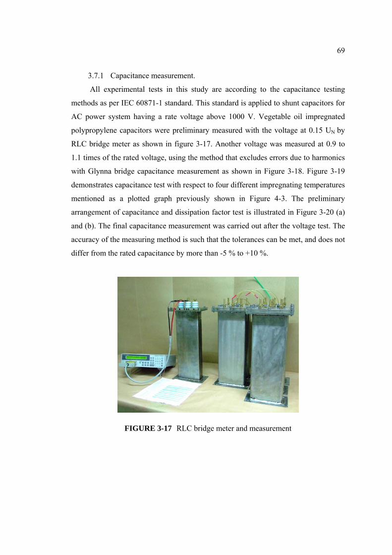
3-17 RLC bridge meter and measurement 69
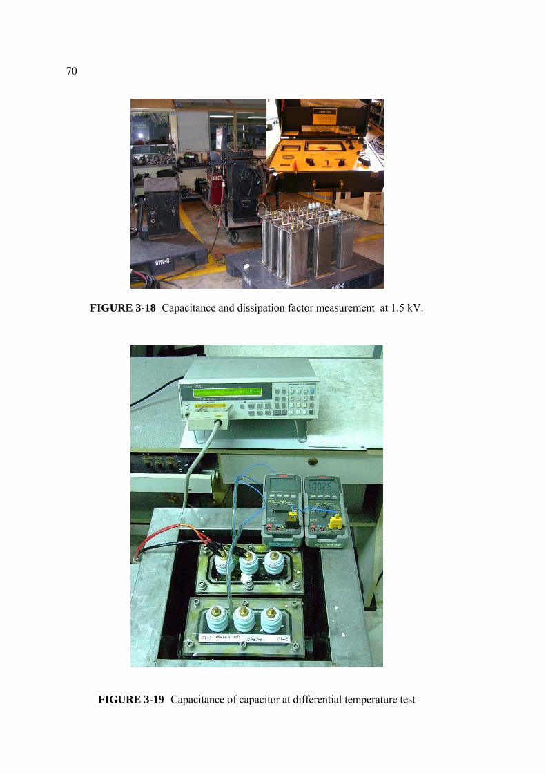
3-18 Capacitance and dissipation factor measurement at 1.5 kV. 70
3-19 Capacitance of capacitor at differential temperature test 70
3-20 Capacitance and dissipation factor test at 500 V for the first of test 71
3-21 AC withstand voltage test between terminals 71
3-22 DC withstand voltage test between terminals 72
Page 10
x
LIST OF FIGURES (CONTINUED)
Figure page
3-23 Short circuit discharge test 73
4-1 Plotted capacitances of sunflower oil impregnated capacitors
at four different impregnating temperatures 80
4-2 Plotted capacitances of soybean oil impregnated capacitors
at four different impregnating temperatures 80
4-3 Plotted capacitances of Envirotemp FR3 impregnated capacitors
at four different impregnating temperatures 81
4-4 Plotted capacitances of sunflower oil impregnated model capacitors
at four different impregnating temperatures 82
4-5 Plotted capacitances of soybean oil impregnated model capacitors
at four different impregnating temperatures 83
4-6 Plotted capacitances of Envirotemp FR3 impregnated model capacitors
at four different impregnating temperatures 84
4-7 Plotted capacitances of vegetable oils impregnated model capacitors
for element thickness 9.0 mm 85
4-8 Plotted capacitances of Vegetable oils impregnated model capacitors
for element thickness 9.4 mm 85
4-9 Plotted dissipation factors of sunflower oil impregnated model
capacitors at four different impregnating temperatures 88
4-10 Plotted dissipation factors of soybean oil impregnated model
capacitors at four different impregnating temperatures 89
4-11 Plotted dissipation factors of Envirotemp FR3 fluid impregnated
model capacitors at four different impregnating temperatures 90
4-12 Plotted dissipation factors of model capacitors impregnated with
vegetable oils for element thickness 9.0 mm 91
4-13 Plotted dissipation factors of model capacitors impregnated with
vegetable oils for element thickness 9.4 mm 91
4-14 Plotted changes in capacitance of model capacitors impregnated
with three fluids at four different impregnating temperatures 93
Page 11
CHAPTER 1
INTRODUCTION
In this chapter, basic terms and structures related to oil impregnated capacitors
are explained. These are high voltage capacitor, oil impregnated polypropylene film
capacitors, vegetable oil in power capacitor, and vegetable oils. An overview
including the purpose and the background has also been done to illustrate the
orientation of this research.
1.1 High voltage capacitor
The high voltage capacitor is a required element in the electrical power system.
It is applied to power factor correction in medium voltage and high voltage, DC high
voltage system and impulse generator. Most of power factor correction capacitors use
polypropylene film as the dielectric. Because polypropylene film is the least of
dielectric loss. For a better capability in their applications, It is impregnated with the
synthesis ester fluid.
Polychlorinated biphenyl are the synthesis ester fluids that used in the high
voltage capacitor. But they are toxic to human and the environment such as being a
carcinogenic substance, it was considered to be banned [1]. As a result it is necessary
to search for a substitution which should be an environmental and human friendly
impregnant. This also never causes any pollution problem in the future.
Castor oil is the first replaceable material used as an impregnant inside Kraft
paper capacitors. Although this fluid is superior in the application for the DC high
voltage and discharge capacitor, its viscosity is significantly high. Developers found
that there are five interesting vegetable oils to consider whether they are suitable to
use as an impregnant in high voltage capacitors. These are sunflower oil, soybean oil,
canola oil, rapeseed oil, corn oil and Envirotemp FR3. All of these fluids are
biodegradable and have good electrical attributes. In addition, their viscosities are
lower than the castor oil. At 100 ํC, their viscosities are nearly the same as synthesis
ester fluid.
Page 12
2
Typically, high voltage capacitors are applied in the field of induction heating,
pulse, commutation, broadcast transmission, drives, bypass equipment, igniters,
frequency converters, filters, high voltage power supplies, snubbers, couplers, voltage
dividers, spark generators and harmonic filters. Voltages applied to these capacitors
are in the range of 1 to 300 KV, and capacitances from 100 pF to 5000 µF.
1.2 Oil impregnated polypropylene film capacitor
The oil impregnated polypropylene film capacitor is constructed of oil
impregnated polypropylene films wound together inside the element. The
determination of polypropylene film used in an oil impregnated capacitor relates to a
stretched, rough electrical insulating film of polypropylene, comprising zones having
different degrees of roughness which lie side by side and form fine channels between
each other. The polypropylene film is particularly suitable for the fabrication of
impregnated capacitors and for the sheathing of cables. The determination relates also
to a process for the manufacture of such film. Materials presently used inside these
impregnated capacitors are often combinations of paper-aluminum, paper-
polypropylene film-aluminum, or paper-metalized polypropylene film [2].
Generally, there are various types of polypropylene film capacitors made by
such material combinations. When considering the trend in constantly decreasing
dimensions of electrical components, development tends toward capacitors which are
constructed of polypropylene films and aluminum or of metalized polypropylene
films only and which are called "all-film capacitors".
In the past, there was a development in improving impregnate ability of oil
polypropylene film used in this type of capacitor, in which the film was roughened by
systematically influencing the morphology. Although it has been possible to improve
the impregnation of capacitors produced from films manufactured according to these
processes, non-impregnated areas cannot be completely eliminated and, as a
consequence, the above-described disadvantages experienced with smooth films will
still occur.
The following development in polypropylene film used in this oil impregnated
capacitor was by adopting super high-purity capacitor-grade homo-polypropylene
resin; the rough film is produced by biaxial-orientation tented process. This kind of
Page 13
3
film features excellent physical and electrical properties, such as good profile
evenness, high electric strength, low dielectric dissipation and good wind ability etc.
The film can be compatible well with several types of oil impregnated capacitors.
According to the investigation by National Power Capacitor Test Center [3], this new
developed polypropylene film conforms to all the requirements of capacitor insulation
materials. Thus, it is widely used as dielectric in the oil impregnated polypropylene
film capacitor as well.
1.3 Vegetable oil in power capacitor
In general, energy storage power capacitors are designed to meet the needs of
each specific application. These include magnetizing equipment, laser, fusion
research, metal farming equipment, strobes, and defibrillators. Power capacitors used
in the light duty and low repetition rate applications that required high energy density
are made with either metalized polypropylene or metalized Kraft paper. Besides, an
aluminum foil is functioned as the extended electrodes with soldered connection. The
dielectric for these can be selected from either polypropylene or Kraft paper with a
specially refined castor oil impregnant; for example, impulse capacitor for impulse
generator.
Power capacitors are important elements that can help in proper design of
transmission and distribution networks, reduce system losses, control the voltage, and
reactive current. Due to the facts, the capacitor fluid is the core material in a capacitor
which eliminates voids by permeating through the solid dielectric, as internal voids
results in electrical discharges leading to premature failure of dielectric system. In
addition, it serves as a heat transfer medium by dissipating heat generated inside the
windings. Since two decades, the search for a reliable, environmental friendly
capacitor fluid was on throughout the world.
This research aimed to determine a metalized film power capacitor used in an
alternating current, more particularly to such the capacitor constructed with dry film
capacitor bodies employing a vegetable oil as an impregnant. Appropriate vegetable
oils which may be applied in the oil mixture of the present invention are selected from
sunflower seed oil, rapeseed oil, soybean oil, castor oil and maize or corn oil.
Page 14
Comparison of Dietary FatsDIETARY FATCastor oil** 2%→Canola oilSafflower oilSunflower oilCorn oilOlive oilSoybean oilPeanut oilCottonseed oilLard*Beef tallow*Palm oilButterfat*Coconut oil
MONOUNSATURATED FAT
Source : POS Pilot plant Corporation Saskatchewan, CANADA June 1994
commercial approach these oils are extracted primarily from seeds of oilseed plant
** Refer to wikipedia free encyclopedia: http://en.wikipedia.org and not food ingredient
(Oleic acid almost)
POLY UNSATURATED FAT SATURATED FAT
1.4 Vegetable oils
Vegetable oils are triglyceride-based fluid-staged materials extracted from
plants. Although there are several parts of plants that can yield oils, but in a
4
Linoleic Acid
Alpha-Linolenic Acid (An Omege-3 Fatty Acid)
FIGURE 1-1 Comparison of dietary fats
* Cholesterol content (mg/tbsp):Lard 12 ;Beef tallow 14;Butter fat 33
Fatty acid content normalized to 100 %
cosmetics, pharmaceuticals, discharge capacitor and other industrial purposes [4].
Although there are glycerin esters and various mixtures of fatty acids, these oils
contained free fatty acids and diglycerides as well. Vegetable oils are increasingly
in actual. Vegetable oils, of food grade, are distinct by dietary fats which are
expressed in Figure 1-1. Triglyceride fats are contained not only in edible vegetable
oils, but also in some other inedible vegetable oils such as processed linseed and
castor oil. These inedible oils are widely used as the elements in lubricants, paints,
←1% 47%
←Trace 48%
←1% 39%←Trace% 39%
←1% 28%
19%
23%←1% 75%
29%16%14%
10%
68% 3%→91% 2%→
51% 48% 2%→43% 27% 19% 15% 15% 13% 12% 10% 7%
21%
76% Trace→ 71% 1%→ 57% 1%→
9% 54% 8%
11%
33% 54% Trace→
9%
7%
←3% 94% ( 90% Ricinoleic acid 4% Oleic acid ) 1%→ 61%
8% 33%
Page 15
5
used in the electrical industry as an insulator since they are non-toxic to the
environment, biodegradable if spilled and have high flash and fire points. Vegetable
oils, however, have to be traded-off their benefits with biodegradable characteristics.
Thus, they are generally used in systems with no exposure to the atmospheric oxygen
and are much more expensive than crude oil distillated ones.
As mentioned, vegetable oils have high stability to an oxidation reaction so they
have found to be used as engine lubricants. Vegetable oils are mostly applied to
produce bio-degradable hydraulic fluid and lubricant. Normally, vegetable oils have
also been used experimentally as cooling agents in PCs. The only limit factor in
industrial purposes for vegetable oils is that all such oils can eventually be
decomposed and turned into rancid by their chemical reaction. Vegetable oils that are
more stable, such as mineral oil and synthesis ester fluid, are preferred for some
industrial uses. Some vegetable oils are suitable for being the liquid dielectric since
they have a high dielectric breakdown voltage and high flash point characteristics.
These oils are, for example, castor oil, rapeseed oil, sunflower oil and soybean oil.
1.4.1 Sunflower oil: Sunflower oil is the non-volatile oil extracted from
sunflower seeds. It is commonly used for frying foods and being an element of some
cosmetics such as a skin softener. Predominantly, it contains linoleic acid in
triglyceride formatted. The British Pharmacopoeia had listed that these sunflower oils
produced can be categorized into two types regarding their linoleic acid containments.
These are high linoleic and mid oleic sunflower oil, which typically contained at least
82% and 69% of linoleic acid respectively. A variation in fatty acid profile is strongly
influenced by both genetics and climate.
In addition, sunflower oil contains high essential vitamin E and low saturated
fat. The two most common types of sunflower oil are linoleic and high oleic. Linoleic
sunflower oil is common cooking oil that has high levels of the essential fatty acids
called polyunsaturated fat. It is also known for having a clean taste and low levels of
trans fat. High oleic sunflower oils are classified as having monounsaturated levels of
80% and above. Recently, sunflower oil has been developed as a hybrid containing
linoleic acid. They have monounsaturated levels lower than other oleic sunflower oils.
The hybrid oil also has lower saturated fat levels than linoleic sunflower oil.
Sunflower oil of any kind has been shown to have cardiovascular benefits as well.
Page 16
6
1.4.2 Soybean oil: To the world, soybean is an important cereal crop, which
also provided oil and protein. Solvent-extracted soybeans turned them into the
vegetable oil and defatted soybeans can also be used as animal feed. A small
proportion of the crop is consumed directly by humans. Soybean products do appear
in a large variety of processed foods.
The major unsaturated fatty acids in soybean oil triglycerides are 7% linolenic
acid (C18:3); 51% linoleic acid (C-18:2); and 23% oleic acid (C-18:1). It also
contains the saturated 4% of fatty acids and 10% of stearic and palmitic acid. The
soybean oil has a relatively high proportion, 7–10%, of oxidation prone linolenic acid,
which is an undesirable property for continuous service, such as in a restaurant. This
kind of oil contains 1% of linolenic acid. There were three companies, Monsanto,
DuPont/Bunge, and Asoyia who introduced low linolenic, (C18:3; cis-9, cis-12, cis-15
octadecatrienoic acid) Roundup Ready soybeans to the world in 2004. In the old days,
hydrogenation was used to reduce the instauration in linolenic acid, but this produced
the unnatural trans-fatty acid trans fat configuration, whereas in nature the
configuration is in cis formatted.
1.4.3 Envirotemp FR3 fluid: This fluid is a Fire Resistant Natural Ester based
dielectric coolant specifically formulated for use in distribution transformers [5]. It is
unique environmental, fire safety, chemical, and electrical properties are
advantageous. Envirotemp FR3 fluid is produced from edible seed oils and food grade
performance enhancing additives. Hence, it does not contain any petroleum,
halogens, silicones or any other hazardous material. It can be quickly and thoroughly
biodegraded in both soil and aquatic environments. This fluid showed non-toxic
characteristics in aquatic toxicity tests. Artificially, it is tinted green to reflect its
favorable environmental profile.
Also, Envirotemp FR3 unique characteristics are its high fire point of 360°C
and flash point of 330°C. It has the highest ignition resistance of less-flammable
fluids currently available. Being referred as a High Fire Point or “less-Flammable”
fluid and listed as a Less-Flammable Dielectric liquid by Factory Mutual and
Underwriters Laboratories made it suitable applications used in complying with the
National Electric Code (NEC) and insurance requirements.
Page 17
7
In addition, Envirotemp FR3 fluid is also compatible with standard transformer
insulation materials, components and with liquid processing equipment and
procedures. It has particular and most preferable thermal characteristics with a
viscosity closer to conventional transformer oil, superior dielectric strength in new
and continued service applications, and excellent chemical stability overtime.
TABLE 1-1 Envirotemp FR 3 fluid Values, and specification limits for natural
ester fluid and mineral oil
Envirotemp FR3 is the trademark of COOPER Power systems
Since that it has excellent environmental, fire safety and capable characteristics,
applications for Envirotemp FR3 fluid have been expanded into a variety of other
equipments, including sectionalizing switches, transformer rectifiers, electromagnets,
and voltage supply circuits for luminaries. Other potential applications under previous
studies include voltage regulators, high voltage cables, and power substations.
New AS-Received Fluid Tested property ASTM
Method
Typical Envirotemp FR3 fluid ASTM
D6871 ASTM D3487
Dielectric Breakdown(kV)
1 mm gap 2 mm gap
D877 D1816
50-55
28-33 60-70
≥ 30
≥ 20 ≥ 35
≥ 30
≥ 20 ≥ 35
Kinematic Viscosity (cst)
40°C 100°C
D445 32-33 7-8
≤ 50 ≤ 15
≤ 12.0 ≤ 3.0
Water Content (mg/kg) D1533 20-30 ≤ 200 ≤ 35
Dissipation Factor (%)
25°C 100°C
D924 0.02-0.06
1-3
≤ 0.20 ≤ 4.0
≤ 0.05 ≤ 0.30
Volume Resistivity (Ω-cm)
D1169 20-40 x 1012
-
-
Pour Point(°C) D97 -18 - -21 ≤ -10 ≤ -40 Flash Point (°C) D92 325-330 ≥ 275 ≥ 145
Fire Point (°C) D92 355-360 ≥ 300 -
Page 18
8
TABLE 1-2 Typical initial Envirotemp FR3 fluid properties
Electrical Property Value Test Method
Dielectric Strength 56 kV@25°C (0.080 gap) 47 kV @25°C
ASTM D1816 ASTM D877
Kinematic Viscosity 33 cSt @ 40°C 8 cSt @ 100°C ASTM D445
Relative Permittivity [Dielectric Constant] 3.2@25°C ASTM D924
Moisture Content 20 mg/kg ASTM 1533B Dissipation Factor [Power Factor] 0.05%@25°C ASTM D924
Volume Resistivity 30 x 1012 Ω-cm @ 25°C ASTM D1169
Pour Point -21°C ASTM D97 Flash Point (Open Cup) 330°C ASTM D92
Fire Point 360°C ASTM D92 Envirotemp FR3 is the trademark of COOPER Power systems
1.5 Purpose of the study
1.5.1 To study the electrical properties of vegetable oil and oil purification
system
1.5.2 To study the design of vegetable oil impregnated polypropylene film
capacitor
1.5.3 To study the capacitor impregnation process and find the most suitable
impregnating temperature for producing vegetable oil impregnated polypropylene
film capacitor
1.5.4 To determine characteristics of vegetable oil impregnated polypropylene
film capacitor
1.6 Scope of the study
This research investigates the process of producing the polypropylene film
capacitors impregnated with three types of vegetable oils. Sunflower oil, Soybean oil
and Envirotemp FR3 fluid are taken into consideration. The process, prior to this
research, contains the purification of Sunflower oil and Soybean oil to have
Page 19
9
electrical properties with respect to the standard specifications of natural ester fluids;
design and production of the polypropylene film capacitors impregnated at four
different levels of temperature, determination of space factor effect, suitable
impregnating temperature and capacitor characteristics.
1.7 Methods
1.7.1 Purify vegetable oil and determine typical values of electrical properties
by standard test method
1.7.2 Design and produce capacitor elements according to manufacturing
1.7.3 Impregnate the elements of polypropylene film capacitors with Sunflower
oil, Soybean oil and Envirotemp FR3 fluid at four different levels of temperatures
1.7.4 Capacitor test in accordance with IEC 60871-1 standard
1.7.5 Analyze results of the test by calculation and graphic plot
1.8 Tools
1.8.1 Small vegetable oil purification system
1.8.2 Sunflower oil, Soybean oil and Envirotemp FR3 Fluid
1.8.3 Elements of impregnated polypropylene film capacitor
1.8.4 Model capacitors impregnated tank
1.8.5 Heating tank with temperature control
1.8.6 Boiler tank with temperature control and clear vacuum chamber
1.8.7 Two stage vacuum pump
1.8.8 High volt laboratory with AC and DC medium voltage testing.
1.8.9 Liquid insulation tester
1.8.10 Electric strength of insulating materials tester
1.8.11 Capacitance bridge meter
1.8.12 Capacitance and dissipation factor tester
1.9 Utilization of the study
1.9.1 The knowledge of vegetable oil purification system
1.9.2 The designing of the polypropylene film capacitor impregnated with
vegetable food oil
Page 20
10
1.9.3 The suitable impregnating temperature of sunflower oil, soybean oil and
Envirotemp FR3 fluid for impregnated polypropylene film capacitors
1.9.4 The vegetable oil impregnated polypropylene capacitor characteristics.
1.10 The structure of thesis
This research presents the study of a feasible occasion in the manufacturing of
polypropylene film capacitors impregnated with three of vegetable oil types.
Capacitor elements are designed and impregnated at four different levels of
temperature, space factor, and capacitor characteristics.
This paper contains five chapters. In the following chapters are:
Chapter 2: Previous works on power capacitors, material properties in high
voltage capacitors and flattened wound capacitors
Chapter 3: Vegetable oil purifier, electrical property test, design and assembly
of model capacitors, impregnating process and testing method
Chapter 4: Measured results of capacitance, dissipation factor, withstand
voltage and short circuit discharge test
Chapter 5: Conclusion of the research and recommendation for further work
Page 21
CHAPTER 2
MATERIAL PROPERTY IN HIGH VOLTAGE CAPACITOR
2.1 Previous works on power capacitor
This session focuses on support information from previous researches involved
with oil impregnated polypropylene film power capacitors. The summary of related
papers will be included in this chapter as well.
One interesting literature focused on oil-impregnated film HV capacitors [6].
The purpose of this journal was to determine the breakdown behavior of
Polypropylene film with/without rapeseed oil impregnation as function of
temperature. The aging test was measured with their life-time acceleration under
higher electric fields and temperatures compared with operating field and
temperature. Polypropylene film was chosen as dielectric because of its superiority in
dielectric strength and permittivity. Dehydrated rapeseed oil was used as an
impregnant processed in closed glass containers within a circulation air oven.
The breakdown strength of this experiment can be measured in accordance with
DIN 0303 standard. The authors found that when the temperature was increased, the
breakdown strength of dry and impregnated PP films was decreased accordingly.
Beside, the impregnant, rapeseed oil, help enhanced the breakdown strength of the
films by 25% or more. They also found that increasing oil impregnation temperature
brought to the increase in breakdown strength. In addition, the impurity of the PP film
itself from additives brought to the abrupt change of slope in breakdown strength.
They concluded that additives in PP film can cause the unfavorable breakdown
behavior at higher temperatures. This study recommended further researches that oil
solubility should be high enough so that the impregnation is completely distributed
throughout the polymer. Also, oil and PP film should be well and carefully chosen to
provide no influence from any reactive group or additive to the experiment.
The other interesting paper focused on the rapeseed oil derivative as a new
capacitor impregnant [7]. This research was subjected to evaluate other types of fluids
as a replacement of the well-known toxic and non-biodegradable agent, Poly
Page 22
12
Chlorinated Biphenyls (PCB) which has been used for decades. Methyl ester from
rapeseed oil (MRSO in short term) was chosen as an impregnant. The evaluation has
been done in comparison to other commercial capacitor fluids (i.e. Midel, Baylectrol,
and PCB). This MRSO was made by transesterificating process using excess
methanol. Its flash point, pour point, and lower viscosity are imperative to capacitor
applications. In addition, the dielectric constant of MRSO is at moderate level which
is suitable to this application. With its low value of dissipation factor, the power loss
in a capacitor can be optimized.
In their empirical process, there were two coupling capacitors impregnated with
MRSO fabricated in a close collaboration from the manufacturer. The investigation
was all referred to IEC 358-1971 standard. It was resulted that the capacitance and
voltage acquired was obtained well within specified limits. The discharge magnitudes
showed no change during the last ten minutes of voltage application. In addition, the
measurement of temperature coefficient ranged from -10 to 65 °C exhibited a very
small value which were not significant nor exceed the manufacturer’s restriction. The
investigation recommended further studies to pursue on the in-depth research of this
MRSO impregnant, which was proved that it can be replaced to existing fluids. They
concluded that MRSO’s electrical properties were mostly compatible with those
commercial fluids used in capacitors. Pursuing previous investigation on MRSO [8], the same authors made a
consequential study of this fluid impregnated in power capacitors. The reason was
that during these two decades the demand of power generation has outgrown the
supply and there was also a requirement in energy conservation by improving the
system design. Due to the facts, Central Power Research Institute or CPRI
(Bangalore) had developed 10 kVAR MRSO impregnated power capacitors which are
already qualified as per IS2834-1986. Some had been installed in related industries
and worked satisfactory. This paper aimed to study about the production and
evaluation of MRSO impregnated power capacitors in pilot scale, which consisted of
two experimental tests.
The first test of this paper was done related to MRSO properties itself. They
found that all of its properties were satisfied when compared to other fluids and can
be used as an alternate impregnant in power capacitors. The second test was arranged
Page 23
13
according to IS2834-1986 standard, to investigate two types of MRSO impregnated
capacitors; the LT and HT power capacitor. For LT capacitor test, it showed that all
figure was passed and qualified. The HT capacitor test result, however, was failed.
Explanations were that its close proximity to the edge of aluminum foil electrode and
the close proximity to an electrode or from the top metallic plate used for stacking
might cause this failure. It was concluded that the review of design and manufacturing
process for HT capacitors is required. Besides, the test of MRSO properties itself
showed satisfactory result when compared to other existing fluids. In addition, it was
encouraged to any future research to determine the opportunity of using rapeseed oil
extracted agent in pilot scale, especially for the capacitor industry.
Back in 1999, the application of polypropylene film with capacitors was
determined [9]. This literature aimed to summarize research results of Biaxially
Oriented Polypropylene Film (BOPP) and provide an experimental test in the
application performance of this material. This paper stated that the performance in
reserving energy of capacitors mainly depends on dielectric constant (ε) and the
square of the electric withstanding capability (E2). There are several drawbacks
caused by its physical properties which lead to the lower performance and the
breakdown of capacitors. These disadvantageous attributes are voids and impurities.
Because it is important for the capacitor design to increase the electric withstanding
capability, those newer designs of BOPP filmed capacitors are required to be
evaluated.
Focusing on their experimental tests, the first investigation was on the capacity
performance. There were two methods for this necessary evaluation; the electrode and
element method. The first method was inexpensive and easy to carry out, while the
second method was much more expensive and difficult in carrying out than the first
one but intensively significant in its accuracy and certainty. With both methods
applied, authors found that, in terms of breakdown and field intensity, some
capacitors were qualified using the electrode method but proved tin pot under the test
using the second method. The second investigation was to check out if capacitor’s
surface condition itself could influence the impregnate performance and the capability
of electric withstanding in BOPP film or not. The setup of this test was to impregnate
three types of BOPP filmed capacitors; the non-roughened film, one side roughened
Page 24
14
film and double sides roughened film, into an impregnant and measure their
capacitance values in every hour. The figures showed that the double sides roughened
filmed capacitor was best performed in impregnate performance, followed by the one
side roughened filmed and non-roughened filmed one. The explanation was that the
double sides roughened film help increased voids between the film and aluminum
foil, which brought to an improvement of impregnate performance of the capacitor.
With the electric withstanding capability comparison test of the one side and double
sides roughened filmed capacitor, their average electric withstanding values (MV/μm)
showed no significant difference. The next investigation was on the compatibility of
BOPP film with impregnant. In this case, the authors used PXE and M/DBT as
impregnants. It was found that swelled and resolved degree of BOPP film in M/DBT
impregnated was smaller than in PXE due to the lower in molecule weight and
viscosity. The final investigation was to optimize the combination usage of BOPP
film with impregnants. For the test, 4 model capacitors was produced from BOPP film
with the same physical attributes; the width of the film and aluminum foil, number of
layers, impregnant applied, and the capacitance. Three constraints were taken into
consideration; the relation between dielectric loss (tanδ) and capacitance, the relation
between partial discharge and temperature, and the endurance of capacitors. From this
experiment, it was found that tanδ values of all tested capacitors within all range of
temperature were smaller than 5x10⁻⁴ and failed within the designed restriction.
Additionally, the partial discharge performance of all capacitors was up to the demand
within the temperature limitation. For the endurance investigation as per GB 11024-
89 Chinese National Standard, there was no breakdown in any model capacitor. It also
showed that there was a small influence from the overload and over voltage to
capacitors, but the purity effect brought the tanδ values down to about 50%. This
paper concluded that no matter the capacitor was one side or two sides roughened, it
took no effect to the performance. Besides, the element method was rather
recommended than the electrode method due to its accuracy and certainty. For any
further study, the authors’ guideline was to focus mainly on electric withstanding
capability and the compatibility with impregnant of BOPP film because these were
important indexes when considering about the development of power capacitors.
Page 25
15
In 2006, there was a research on the loss tangent (tan δ) on cleaning effect for
oil in oil impregnated all-film capacitors [10]. This value was said to be the life or
aging acceleration factor in any oil-impregnated all-film shunt capacitor. To lengthen
the life expectancy value of a shunt capacitor, this parameter should be considered
when designing a new capacitor. The tanδ value of capacitor film and oil affects
directly to the tanδ value of a capacitor, which means that the lower value in tanδ of
the oil and film applied leads to the lower value in tanδ of a capacitor, also. The
partial discharge process (PD) must be carried out in order to clean the oil
impregnated in shunt capacitors so that their tanδ value were lower. In this paper,
there was a particular design and production of model capacitors. Three model
capacitors impregnated with oils of different tanδ were investigated. In each model
capacitor, eight element capacitors were contained. Connected through one common
terminal sharing, the average values of these element capacitors were measured. For
this study, Polypropylene (PP) was used as the capacitor films and Phenyl Ethyl
Phenyl Ethane (PEPE) was applied as the impregnant inside. The aging of capacitors
were accelerated by placed them in an oven at the temperature of 75 °C for 500 hours.
Finally, aged capacitors were taken out and the oil inside model capacitors but outside
element capacitors was measured for tanδ values by the method of Chromatography-
Mass Spectrometry (GC-MS).
Upon the test, result was that after applying specified voltage, measured tanδ
value of first model capacitor was the same, while second capacitor and third
capacitor was lower to nearly the same as the first unit though their calculated tanδ
value should be at 10 and 20 times of its pre-measured value, respectively. The tanδ
value of aged model capacitors showed that there was a small change in each
capacitor when compared between the figures just before and after the process.
Furthermore, the PD value of all capacitors was close to each other after aging
process with a little higher amount than before the aging had been done. The PDIV
measured values of model units also showed the similar pattern; rising at the
beginning and falling at the end of this aging process. It was concluded that though
elements capacitors inside the second and third capacitor, impregnated with inferior
oil than the first one, were not deteriorated much and their qualities were in good
shape as element capacitors inside the first model capacitor after the aging process.
Page 26
16
This phenomenon was caused by the cleaning effect for oil during impregnation and
the aging process. The reason was that most of impurities (larger than 1 μm) were
mainly blocked by the elements. However, some small impurities could invade into
these elements which brought to the effect mentioned. The oil inside the elements was
then trapped and could not diffuse with the outside oil. This caused to the reduction of
tanδ values in other model capacitors as well.
There was an investigation of vegetable oil characteristics in HV AC capacitors
in 1995 [11]. In this study, commercial-grade rapeseed oil and polypropylene film
was chosen as the impregnant and the dielectric of the test. The fluid was purified and
filtered, and impregnated into the film. The capacitor models were accelerately aged
and measured for their electrical losses, average breakdown voltages, and discharge
characteristics. Along with this setup, there was a parallel investigation of an existing
impregnant such as benzyltoluence (BT) which was mainly composed of an ester of
pentaerythritol (EPE) and the mixture between rapeseed oil and BT. Finally, figures
of these two impregnants obtained from the measurements were compared and
analyzed. In term of the absorption, tested rapeseed oils nearly proportioned to the
concentration. In this case, there was no interaction between the oils and PP films. In
the breakdown strength, PP films impregnated with rapeseed oil with 10% BT were at
normal agreed range, with larger breakdown strength when films used were thinner.
Their discharge characteristics of rapeseed oil impregnated films itself can be
improved by addition of an aromatic liquid, which could be achieved and qualified
near the characteristics of M/DBT. With additional concentration in BT of more than
25%, impregnated films made the metallization cracked by the swelling. Finally, the
capacitor models were tested. The models, made of two rough PP films pressed, were
placed with the temperature at 80ºC in Q2 atmosphere to accelerate the electrical
degradation of PP films inside.
From the measured figures, the breakdown voltage of rapeseed oil impregnated
PP films was somewhat inferior when compared to those BT impregnated. Also, it
was found that the breakdown voltage of PP films with rapeseed oil/BT mixture
impregnated was about 10% larger than PP films with BT impregnated. The
conclusion of this paper stated that although rapeseed oil impregnant’s electrical
characteristics were less favorable than BT, these characteristics could be improved.
Page 27
17
Some attributes of rapeseed oil fluid such as resistivity and the inception voltage of
discharges could be treated to the optimization of usage by additional aromatic liquid.
The most important attribute and was advantageous to rapeseed oil impregnant was
that, there was no crack of the metallization when increasing its concentration or
swelling. This study also recommended further research to investigate impregnated
liquids other than this rapeseed oil, or the mixture between the rapeseed oil and other
liquids, to study about the influence of various additives.
Also in 1996, there was an investigation on increasing the breakdown,
especially in DC voltage, in oil-impregnated filter capacitors [12]. The reason was
that DC filter capacitors are widely used in electronic apparatus, which are subjected
to hard service conditions with their capacitance of about 600 µF. In this paper, model
units consisted of the PP film, the Kraft paper/PP mixed dielectric, and the M/DBT
impregnant with additional cleaning to help increasing their electric stresses. The
authors claimed that there were two advantages in using M/DBT as an impregnant.
Firstly, its distribution is well uniformed for AC electric stress in the film and layer.
Secondly, its electric loss is low. The model dielectric was made of a basic resin. The
rough film was 7 to 7.8 μ in compromised thickness with controlled surface roughness
to facilitate the completeness of its oil impregnation. For the measurement of
dispersion in breakdown stress, it was found that values of DC breakdown stress were
higher than AC ones. The more of DC voltage applied to DC filter capacitors, the
higher to their failure rate. In the pollution effect investigation of DC dielectric
strength, results were that the all-film unit with polluted liquid impregnated was
increase in their dielectric strength when compared with a reference capacitor which
had no impurity in its impregnant. Moreover, the DC dielectric stress was varied
directly to the liquid resistivity at certain linear rate. When reducing its resistivity, it
was also meant to an increase in the total dielectric breakdown of the capacitor,
especially at the low temperature. It was also an important note that, when increasing
the additive cleaning in their impregnants, model units tended to be decreased in the
number of element failures because of an improvement in its dielectric stress
property.
Due to the satisfactory results of all investigation on power electronic capacitors
obtained from this study, which was according to the IEC 1071-1 standard, the
Page 28
18
authors concluded that the model capacitors were qualified and achieved in their
successful records.
2.2 Dielectric materials
A dielectric material is a substance that is inferior in electrical conduction, but
efficiently support in electrostatic field property. An electrostatic field can help store
energy if the flow of current between opposite electric charge poles is minimally kept
while the electrostatic lines of flux are not impeded or interrupted. This property is
useful in capacitor applications and the construction of radio-frequency transmission
lines.
Most of dielectric materials are actually in solid state. These materials include
ceramic, mica, glass, plastics, and the oxides of various metals. Besides, some liquids
and gases can serve as good dielectric materials. In practice, an excellent dielectric is
dry air, and is used in variable capacitors and some types of transmission lines. Also,
distilled water can be used as a fair dielectric. A vacuum is an exceptionally efficient
dielectric.
As mentioned, one of the most important properties in a dielectric is its ability
to support an electrostatic field while dissipating minimal energy in the form of heat.
The lower the dielectric loss (the proportion of energy lost as heat), the more effective
is a dielectric material. Another important electrical property to be considered is the
dielectric constant, the extent to which a substance concentrates the electrostatic lines
of flux. Low dielectric constant materials include a perfect vacuum, dry air, and most
pure, dry gases such as helium and nitrogen. Moderate dielectric constant materials
include ceramics, distilled water, paper, mica, polyethylene, and glass. Among high
dielectric constant materials, metal oxides can be included.
Practically, there are three types of electrical properties for dielectric materials
which should take into consideration; the dielectric constant (or relative permittivity),
dissipation factor and dielectric strength.
2.2.1 Dielectric constant. This factor is the ratio of capacitance of a capacitor
with test material as the dielectric to the capacitance of a capacitor with a vacuum as
the dielectric. When determine the performance of a capacitor, its dielectric materials
should have dielectric constant should be high so that the capacitor dimensions can be
Page 29
19
dA
C roεε=
minimized. This factor can be calculated using: εr = Cs/Cv where Cs is the capacitance
with the specimen as the dielectric, and Cv is the capacitance with a vacuum as the
dielectric.
2.2.2 Dissipation Factor. This value is the ratio of the power dissipated in the
test material to the power applied, which is equal to the tangent of the loss angle, or
the cotangent of the phase angle. The dissipation factor can be calculated using;
)CfRπ2(1θcotδtanDF
pp
=== Eq.2-1
where δ = the loss angle,
θ = Phase angle,
f = Frequency,
Rp = Equivalent parallel resistance,
and Cp = Equivalent parallel capacitance.
The determination of chosen dielectric materials for capacitors depends on the
capacitance value, frequency of application, maximum tolerable loss, and maximum
working voltage. The size and cost of required capacitors is also additional external
constraints. In practice, selection criteria of high voltage power capacitors are
distinctly different than those used in small integrated circuits. Large capacitance
values can be acquired at low frequencies due to low-frequency polarization
mechanisms such as interfacial and dipolar polarization. On the other hand, it
becomes more difficult to achieve large capacitances at high frequencies, and at the
same time maintain acceptable low dielectric loss, in as much as the dielectric loss per
unit volume is εoεrωE2 tan δ.
The principles of capacitor design can be determined from capacitance of a
parallel plate capacitor as following,
Eq.2-2
There are various applications for these dielectric loss capacitors, which can
be also made of many different materials in many different styles. Basically,
Page 30
20
capacitors can be classified into three types; AC capacitors, DC capacitors, and
capacitors for pulse applications. AC capacitor is the most widely used because it can
also work with DC and pulse applications. For AC capacitors, it is important to
consider losses in their applications. Losses of a dielectric (except vacuum) can be
divided into two types; conduction loss, and dielectric loss. A conduction loss
represents the flow of actual charge through the dielectric. A dielectric loss is
occurred due to movement or rotation of the atoms or molecules in an alternating
electric field. It is the reason why food and drink gets hot in a microwave oven. One
way of describing dielectric losses is to consider the permittivity as a complex
number, defined as;
δ−ε=ε ′′−ε′=ε jej Eq.2-3
where
ε′ = AC capacitivity
ε″ = Dielectric loss factor
δ = Dielectric loss angle
Capacitance is a complex number C* in this definition, becoming the expected
real number C as the losses approach zero. That is, it can be defined as;
CjCC* ′′−′= Eq.2-4
One reason for defining a complex capacitance is that we can use the complex
value in any equation derived for a real capacitance in a sinusoidal application, and
get the correct phase shifts and power losses by applying the usual rules of circuit
theory. Equation 2-3 expresses the complex permittivity in two ways, as real and
imaginary or as magnitude and phase. The magnitude and phase notation is rarely
used. Instead, people usually express the complex permittivity by ε′ and tan δ,
ε′ε ′′
=δtan Eq.2-5
Page 31
21
Where tan δ is called either the loss tangent or the dissipation factor DF. The
real part of the permittivity is defined as ε′ = εrεo where εr is the dielectric constant
and εo is the permittivity of free space.
They also need to have a lower dissipation factor than capacitors used as DC
filter capacitors. The AC circuit term power factor PF may also be defined for AC
capacitors. It is given by the expression PF = cos θ where θ is the angle between the
current flowing through the capacitor and the voltage across it.
( ) ( )22
cosε′+ε ′′
ε ′′=θ Eq.2-6
For good dielectric, ε′ >> ε″
δ=ε′ε ′′
≈θ tancos Eq.2-7
Therefore, the term power factor is often used interchangeably with the terms loss
tangent or dissipation factor, even though they are only approximately equal to each
other. We can define the apparent power flow into a parallel plate capacitor as
*22
CjVjXc
VVIS ω=−
==
( )ε ′′−ε′ω
= jdAjVS 2
( )ε ′′−ε′ω
= jdAjVS 2 Eq.2-8
By analogy, the apparent power flow into any arbitrary capacitor is
( )DFjCVjQPS 2 +ω=+= Eq.2-9 The power dissipated in the capacitor is
( )DFCVCVP 22 ω=′′ω= Eq.2-10
Page 32
22
Where εr infers εr′. Large capacitances can be achieved by using high εr
dielectrics, thin dielectrics, and large areas. 2.2.3 Dielectric strength. This term can be defined as the maximum electric
field strength of an insulating material that it can withstand intrinsically without
breakdown, or without failure of its insulating properties. In a given configuration of
dielectric material and electrodes, this factor can be assumed as the minimum electric
field that produces breakdown.
2.3 Liquid dielectric
2.3.1 Liquid dielectric: In high voltage applications from molecular
arrangement point of view, liquids can be described as ‘highly compressed gases’ in
which the molecules are closely arranged. It is known as kinetic model of the liquid
structure. For the movement of charged particles, however, their microscopic streams
and interface conditioned with other materials cause a distortion in the otherwise
undisturbed molecular structure of the liquids. The well known terminology
describing the breakdown mechanisms in gaseous dielectrics, such as, impact
ionization, mean free path, electron drift etc. is, therefore, also applicable for liquid
dielectrics.
Liquid dielectrics can be classified in between the two states of matter, which is
a gaseous and solid insulating material. This intermediate position of liquid dielectrics
also characterized by its wide range of application in power and instrument
transformers, power cables, circuit breakers, power capacitors etc. They function as
elements in parts of various systems as following:
2.3.1.1 Insulation between the past carrying voltage and the grounded
container, as in transformers.
2.3.1.2 Impregnation of insulation provided in thin layers of paper or
other materials, as in transformers, cables and capacitors, where oils or impregnating
compounds are used.
2.3.1.3 Cooling action by convection in transformers and oil filled
cables though circulation.
2.3.1.4 Filling up of the voids to form an electrically stronger integral
past of composite dielectrics.
Page 33
23
2.3.1.5 Arc extinction in oil circuit breakers.
2.3.1.6 High capacitance provides by liquid dielectrics whit high
permittivity to power capacitors.
Many natural and synthetic fluids can be used as dielectrics. Physical and
electrical attributes such as electric strength, viscosity and permittivity can be varied
in the wide range. The appropriate application of a liquid dielectric in an apparatus is
determined by its physical, chemical and electrical properties. In addition,
applications also depend upon the requirements of the functions to be performed.
Apart from mineral oils, there are some vegetable oils found to be fitted their
applications in electrical equipments. These available oils are castor, linseed,
rapeseed, soya, groundnut, corn, olive, sunflower, mustard, clove, almond,
mangoseed, cottonseed oils, etc. Basically, there are fatty acids accumulated in
vegetable seeds. Chemically, these are ester compounds produced form sebacic acids
and glycerine. Some volatile vegetable oils, however, have a strong odor and are
extracted from leaves, wood and roots of special plants. Higher the molecular weight
of these oils, more is the specific resistance and lower is the loss tangent (tanδ ).
Most of an important component for the production of ‘oil modified alkaline
resins’ is made from rapeseed, soybean and castor oils. Such resins incorporate the
advantages of oils to improve their elasticity as against the hard dried resins. Soybean
oil whit epoxy resin is known as ‘softener’ for some synthetic materials. Castor oil,
which has hydroxide content of about 5%, is an important polyisocyanide reagent.
The chemical composition of this unsaturated oil which has a high relative
permittivity between 4.2 and 4.5. Castor oil has therefore found wide application as
impregnating agent in power capacitors.
2.3.2 Breakdown in liquids: Liquids are used in high voltage equipment to serve the
dual purpose of insulation and heat conduction. They have the advantage that a puncture path
is self-healing. Temporary failures due to over voltages are reinsulated quickly by liquid
flow to the attacked area. However, the products of the discharges may deposit on solid
insulation supports and may lead to surface breakdown over these solid supports. The
causes of breakdown voltage in liquids are classified into three types; electronic
breakdown, cavitation breakdown and suspended particle mechanism [13]
Page 34
24
Highly purified liquids have dielectric strengths as high as 1 MV/cm. Under actual
service conditions, the breakdown strength reduces considerably due to the presence of
impurities. The breakdown mechanism in the case of very pure liquids is the same as the
gas breakdown, but in commercial liquids, the breakdown mechanisms are significantly
altered by the presence of the solid impurities and dissolved gases.
The most common insulating liquids are made from petroleum refinery oils. Askarels,
fluorocarbons, silicones, and organic esters including castor oil, however, are used in
significant quantities. The selection of dielectric liquid in any application can be considered
by its inherit properties. The important electrical properties of the liquid include the
dielectric strength, conductivity, flash point, gas content, viscosity, dielectric constant,
dissipation factor, stability, etc. Polybutanes are widely used in the electrical industry
Because of their low dissipation factor and other excellent characteristics. Askarels and
silicones are particularly useful in transformers and capacitors and can be used at
temperatures of 200 °C and higher. The suitable application for castor oil is high voltage
energy storage capacitors because of its high corona resistance, high dielectric constant,
non-toxicity, and high flash point.
In practical, most of these liquids are used at voltage stresses of about 50-60 kV/cm
when the equipment is continuously operated. On the other hand, in applications like high
voltage bushings, where the liquid only fills up the voids in the solid dielectric, it can be
used at stresses as high as 100-200 kV/cm. [14]
2.3.3 Standard test method of insulating liquid
There are three electrical properties of liquid taken into consideration; dielectric
constant, dissipation factor and dielectric breakdown. These properties are scoped
within the two standards shown below;
2.3.3.1 Standard testing methods of insulating liquids for relative
permittivity, dielectric dissipation factor (tan δ) and DC resistivity (IEC 60247): This
International standard describes methods for the determination of the dielectric
dissipation factor (tan δ), relative permittivity and DC resistivity of any insulating
liquid material at the test temperature. It is primarily intended for making reference
tests on unused liquids, which can also be applied to liquids in service in transformers
cables and other electrical apparatus. The standard, however, is applicable to a single
Page 35
25
phase liquid only. With insulating liquids other than hydrocarbons, alternative
cleaning procedures may be required.
2.3.3.2 Standard test method for dielectric breakdown voltage of
insulating liquids (ASTM D877-02, 2007): The dielectric breakdown voltage is a
measurement in the ability of an insulating liquid to withstand electrical stress. This
factor can be reduced by contaminants such as water, conducting particles, and dirt.
Lower value of this factor in this test method indicates significant concentrations of
contaminants in the liquid investigated.
2.3.4 Electrical property of liquid dielectric: Core electrical properties of the
liquid considered in this paper, when used as a dielectric, are withstand breakdown
capability under electrical stress, electrical capacitance per unit volume determined by
its relative permittivity, power factor or loss tangent which is an indication of the
energy loss under AC conditions, and its resistivity. Some electrical properties of
sampled liquids as a dielectric are shown in Table 2-1[15].
TABLE 2-1 Dielectric properties of some liquid dielectrics
Property Transformer oil
Cable oil
Capacitor oil
PETEP oil
Silicone oil
Breakdown strength at 20ºC on 2.5 mm standard sphere gap
15 kV/mm
30 kV/mm
20 kV/mm
>15 kV/mm
30-40 kV/mm
Relative permittivity (50Hz)
2.2-2.3
2.3-2.6
2.1
2.7
2-73
Tan δ (50Hz) (1kHz)
0.001 0.0005
0.002 0.0001
0.25×10⁻³
0.10×10⁻³ 0.1×10⁻³
0.5×10⁻³ 10-3
10-3
Resistivity (ohm-cm) 1012-1013 1012-1013 1013-1014 >1014 3×10¹⁴
Specific gravity at 20ºC 0.89 0.93 0.88-0.89 0.96-
0.97 1.0-1.1
Viscosity at 20ºC (cst) 30 30 30 80 10-1000
Page 36
26
2.4 Insulating oil purification system
Impurities in liquid dielectrics mostly mean dust, moisture, dissolved gases and
ionic impurities. Purification and filtration process such as centrifuging, degassing
and distillation, and chemical treatment are required to provide uniformity and purity
of these liquids. Dust particles, which reduce the breakdown strength of the liquid
dielectrics, can be removed by careful filtration.
In normal condition, liquids contain a small amount of moisture and dissolve
gases, which can significantly affect the breakdown strength of the liquids, also. This
impurity can be treated by distillation and degassing. Water vapour, an ionic impurity
in liquid, which leads to high conductivity and heating of the can be removed using
drying agents or vacuum drying. A commonly used closed-cycle liquid purification
system to prepare liquids as per the above requirements is shown in Figure 2-1.
INLET
OUT LET
HEATER
INLETPUMP
SAMPULINGVALVE
AFTERFILTEROFFTION( 0.5 MICRON )
DISCHARGEPUMP
CHECKVALVE
VACUUMPUMP
BOOSTERPUMP
TRAP
PRE FILTEROFFTION( 5 MICRON )
TEMPERATUREGAUGETEMP
GAUGE
PRESSUREVACUUM GAUGE
VACUUM BREAKSOLENOID VALVE
VACUUMCHAMBER
PUMPRELIEFVALVE
TEMPGAUGE
PRESSUREVACUUM GAUGE
LEVELCONTRONVALVE
CHAMBERBY-PASS
FIGURE 2-1 Insulating oil purification system
This system can provide purification process of liquid in cycling loops. From
the reservoir, the liquid flows though the distillation column to remove ionic
Page 37
27
impurities. Getting rid of water, applied drying agents or frozen out in the low
temperature bath can be employed. To remove dissolve gases, the liquid is passed
through the cooling tower and/or pumped out by the vacuum pumps. There are two
system filters; pre-filter and after filter, which are taken care of particles screening of
5 and 0.5 micron, accordingly. In this stage, the liquid is purified ready to be used in
the test cell. The liquid used then flows back into the reservoir. The system will begin
purification process again and so on.
Description of process in brief; oil, at ambient or elevated temperature, is
introduced into the vacuum chamber, where by vacuum distillation, water, dissolved
air and gases, and other low-boiling-range volatile contaminants are removed.
There are four functions for chemically-inert accelerator cartridges inside the
vacuum chamber; coalescence filtration before the evaporation stage, expand liquid’s
surface area using glass fibers, releasing gases and vapors from the liquid quickly by
sharp points of the glass fibers, and fine filtration removing solid contaminants. This
method is more efficient than previously used spray nozzles and baffles.
2.5 Polypropylene dielectric
For the experiment, we applied with bi-axially oriented polypropylene film,
two-side rough designed for impregnated film-foil capacitors.
2.5.1 Physical, chemical and thermal properties of polypropylene film: Some
other distinct characteristics of PP film present a crucial influence to test result, too.
There are five characteristics in our determination; specific gravity, water absorption,
maximum continuous working temperature, maximum peak working temperature, and
melting point. Table 2-2 shows these characteristics in details.
2.5.2 Electrical properties of polypropylene film: Five electrical characteristics
are taken into consideration; permittivity, loss factor, volume resistivity, dielectric
strength, and electrical defects. The values of each characteristic of PP film are shown
in Table 2-3.
2.5.3 Dimension properties and space factor of polypropylene film: The
dimension of PP film, especially its thickness, can affect test result during
impregnation process. The impact of different space factor (≥5μm) can also influence
our investigation. These two characteristics; are shown in Table 2-4 and Table 2-5.
Page 38
28
TABLE 2-2 Physical, chemical and thermal properties of polypropylene film
Source: Bollore′ Inc.
TABLE 2-3 Electrical properties of polypropylene film
Characteristics 20°C 100°C Tolerance/ Typical value
2.20 2.15 50Hz Permittivity
1MHz 2.20 2.15 Typical value
1.5 1.6 Loss factor tg δ (10-4)
50Hz
1MHz 1.6 2.5 Typical value
Volume resistivity (Ω-cm) 1018 1017 Typical value
Dielectric strength (Vdc / μm) 560 Typical value 1.3 Number
at 6 μm 1 Number at 8 μm
0.6 Number at 1.2 μm
Electrical defects at 300Vdc /μm
0.5 Number at 15-18 μm
Maximum value
Source: Bollore′ Inc.
Characteristics Value Tolerance/ Typical value
Measurement method or
reference norm
Specific gravity 0.905 Typical value ASTM D 92
Water absorption (%) 0.005 Typical value ASTM D570
Max. working temperature
(continuous) (°C) 100 Typical value
Max. working temperature (peak, °C)
120 Typical value
Melting point (°C) 167 to 169 Typical value DSC
Page 39
29
TABLE 2-4 Dimension properties of polypropylene film
Characteristics Value Tolerance / Typical value
Thickness by weight (μm) 5 go 17.8 +/- 6% on 1m2 of film on roll
weight
Thickness variation in % of nominal
thickness
GR 0 GR + GR -
+2 to -2 % on roll weight +2 to +6% on roll weight -2 to -6% on roll weight
Film width (mm) 8 to 239.5 240 to 398 ≥ 400
+/- 0.5 +/- 0.7 +/- 1
Source: Bollore′ Inc. TABLE 2-5 Space factor of polypropylene film
Source: Bollore′ Inc. The value of space factor can be calculated from Eq.2-3 as following;
% Eq.2-11
Tpm = Micrometer thickness at pressure = 1 Bar (µm)
Tpg = Thickness by weight, by weighing 1 m2 of film, for density = 0.905 (µm)
For Example; two-side roughened polypropylene film is SF = 10 % ,thickness
by weight Tpg = 17.8 µm for density = 0.905 therefore Tpm = 19.58 µm.
2.5.4 Standard test method of solid insulating material
2.5.4.1 Electrical strength of insulating materials - Test methods - part 1
(IEC 60243-1): Tests at power frequencies: It is set to determine the short-time
electric strength of solid insulating materials at power frequencies between 48 Hz and
Characteristics Value Tolerance / Typical value
Measurement method or reference norm
Space factor for thickness 5μm (%) 7.5 +/- -2.5
Space factor for thickness >5μm (%) 10 +/-3
Space factor Measurement
100T
TTSF
pg
pgpm ×−
=
Page 40
30
62 Hz. There is no consideration of liquids and gases testing methods, although these
are specified and used as impregnants or surrounding media for the solid insulating
materials. This standard includes methods for the determination of breakdown
voltages along with the surfaces of solid insulating materials.
2.5.4.2 IEC 60243-2: electric strength of insulating materials - testing
methods - part 2: Additional requirements for tests using direct voltage: This standard
gives methods of test for the determination of the short-time electric strength of solid
insulating materials at direct current voltage. There is no consideration of liquids and
gases testing methods, although these are specified and used as impregnants or
surrounding media for the solid insulating materials.
2.6 Composite dielectric
2.6.1 What is composite dielectric
In general, insulation system can not achieve its task perfectly without
composing of more than two insulating materials. These different materials can be in
parallel with each other, such as air or insulating oil in parallel with solid insulation or
in series with one another. These insulation structures are called composite dielectrics.
Being a part of mechanical requirements, the composite pattern of an insulation
system concerned with separating electrical conductors at different potentials. In
actual, single materials will commonly have at least small volumes of another
elemental material such as gas or voids in a solid. Meanwhile, there may be dust
particles or gas bubbles in a liquid or gas. One common composite dielectric is the
solid/liquid combination or liquid impregnated flexible solid like thin sheets of paper
or plastic. It is widely used in low and high voltage equipments such as cables,
capacitors, transformers, oil-filled switchgear, bushings etc.
2.6.2 Properties of composite dielectric
General speaking, a common composite dielectric can comprise plenty of layers
superimposed one over the other. It is called “layered construction” which can be
found in many applications such as cables, capacitors and transformers. There are
three important properties of composite dielectrics which affect the performance as
following;
Page 41
31
2.6.2.1 Effect of multiple layers: This is advantageous property of
composite dielectric based on the fact that two thin sheets have a higher dielectric
strength than a single sheet of the same total thickness. The advantage is significant
particularly when materials have a wide variation in dielectric strength values
measured at different points on its surface.
2.6.2.2 Effect of layer thickness: For this property, a composite
dielectric’s breakdown voltage will be increased if there is an increase of its layer
thickness. This is because in this layered construction a breakdown can be occurred at
the interfaces only, not directly through another layer. In addition, a discharge
penetrated through one layer can never enter the next one until the interface also
reaches the discharge channel. This is certainly important to the insulating paper since
its thickness can be varied and consequently the dielectric strength across its surface
to the paper which can produce an electric field stress comparable to that of the
discharge channel. Furthermore, impregnation process can be enhanced by the rough
surface of the paper when tightly wound. Whereas the lower thickness areas within
the paper can also cause breakdown even at considerably lower voltages. Previous
studies on composite dielectrics indicated that the discharge inception voltage
depends on the thickness of the solid dielectric, together with the dielectric constant of
both the liquid and solid dielectric. The difference between the liquid and solid
dielectrics in the dielectric constants does not significantly affect the change of
electric field at the electrode edge with the change in the dielectric thickness.
2.6.2.3 Effect of interfaces: Determining pre-breakdown and breakdown
strengths of dielectrics, the interface between two dielectric surfaces in a composite
dielectric system is one of the key factors. Discharges usually occur at the interfaces
and the magnitude of the discharge depends on the associated surface resistance and
capacitance. When the surface conductivity increases, the discharge magnitude also
increases, resulting in damage to the dielectric. 2.6.3 Permittivity of composite dielectric
As the result of reducing electrical breakdown at the interface of two different
insulation materials[18], the interfaces in highly stressed field regions should be
normal to the field lines. The ‘parallel-plate capacitor’ which contains two layers of
Page 42
32
different materials represented by the permittivity 1ε and 2ε is therefore typical for
many applications. Figure 2-2 (a) shows the arrangement and dimensions assume. For
usual dielectric materials with power frequency AC voltage application, the
conductivity of the materials can be ignored and hence no free change is built up at
the interface between the two layers. The displacement vectors D1 and D2 are then
equal, starting from and ending ay the equal free changes on the plate only. As
,ED ε= which is the same in both materials, the ratio of the field strength becomes;
1
2
2
1
EE
εε
= Eq.2-12
(a) (b)
FIGURE 2-2 Capacitor comprising two layers of different dielectric materials:
(a) Smooth parallel plates (b) Parallel plates with oil filled
As the field remains uniform in each layer, the voltage V or potential difference
between the two plates is
2211 dEdEV += Eq.2-13
where d1, d2 are the individual values of the thickness of the two dielectrics.
Introducing Eq. 2-12 into Eq. 2-13, we obtain the following absolute values of E1 and
E2 with reference to the voltage applied:
Page 43
33
⎟⎟⎠
⎞⎜⎜⎝
⎛εε
+=
+⎟⎟⎠
⎞⎜⎜⎝
⎛−
εε
=
⎟⎟⎠
⎞⎜⎜⎝
⎛ε
+ε
ε=
2
121
1
21
2
2
1
11
1
dd
V
11dd
1dV
ddVE Eq.2-14
11dd
1dV
ddVE
1
21
2
2
1
11
2
+⎟⎟⎠
⎞⎜⎜⎝
⎛−
εε
=
⎟⎟⎠
⎞⎜⎜⎝
⎛ε
+ε
ε= Eq.2-15
In theoretical approach, either Eq.2-14 or Eq.2-15 shown above may be applied
in our calculation for the mean value of dielectric materials’ permittivity in
homogeneous mixture such as resin- or oil-impregnated Kraft papers shown in Figure
2-2 (b). These layers mentioned are usually oriented in parallel to the electrodes,
any multiple-dielectric system can be separated into an infinite number of layers
with materials designated by their intrinsic properties ε1 and ε2 and the resultant
permittivity (εres) of composite dielectric can be defined as;
ED resε= Eq.2-16
where D and E are macroscopic mean values. As the microscopic values E1 or
E2 will remain unchanged by multiple layers, we can write
2211res EEED ε=ε=ε= Eq.2-17
or after replacement of E1 or E2 in Eq.2-14 or Eq.2-15 and rearranging the numbers
( ) ( )2
2
1
1res d/dd/d
1dVE
ε+
ε
⎟⎠⎞
⎜⎝⎛=ε Eq.2-18
As before, V/d represents the mean value of the field strength within the
mixture, and the distances can be replaced by relative volumes v1 and v2 as the
relationships d1/d and d2/d represent also the volumes of the two materials. Therefore;
Page 44
34
( ) ( )2211res /v/v
1ε+ε
=ε Eq.2-19
for a mixture of n materials
( ) ( ) ( )nn2211res /v.../v/v
1ε++ε+ε
=ε Eq.2-20
with ∑=
=n
1ii 1v or 100 percent.
Example: An oil impregnated capacitor using a dielectric made from two rough
side polypropylene film that space factor (SF) = 10 % , Tpg = 17.8 µm and Tpm =
19.58 µm. We can calculate the volume of polypropylene film by v1 = 17.8WL , and
space for oil impregnation v2 = (19.58-17.8) WL .
The percent volume of each value is, v1 = (17.8WL)/(19.58 WL) × 100 =
90.91 % or 0.9091 p.u. and v2 = (19.58-17.8)WL/(19.58 WL)×100 = 9.09 % or
0.0909 p.u. , where relative permittivity of polypropylene εr1 = 2.2 and Vegetable
oil εr1 = 3.1. The resulted permittivity εres can be defined according to Eq.2-19 ;
εres = 2.26.
2.7 Wound capacitor flat winding
2.7.1 Basic construction of impregnated polypropylene capacitor
Extended part of foil
Folded part of foil
Extended part of foil
Folded part of foil
Aluminum Foil
Polypropylene Films
Aluminum Foil
FIGURE 2-3 Capacitor Element of flattened wound capacitor
Page 45
35
The element has been pressed flat in the height direction and is called flattened
pressed element. Element or (active) foil length is obtained on unwinding the element
in the length direction. Height is always determined from the side on which the
bushings are fitted, to the opposite side. The process is shown in Figure 2-3.
Normally, the length direction of the flattened element corresponds to the depth
direction of a container. Depending on the design, the element width direction may
correspond either to container height direction or to container width direction.
After being processed, the dielectric and electrodes are ready in thin foil form,
then they can be wound to achieve a technically suitable shape. The principle of a
wound capacitor is shown in Figure 2-3. Generally, the capacitor mentioned will
consist of electrodes made of about 6 μm thick aluminum foil. Sometimes dielectrics
can be made from impregnated paper or plastic films with several layers. The
effective area of an individual winding will become smaller caused by the winding
with each electrode used on both sides. With projected electrodes or so called
extended foils, external connections can be achieved as shown in the figure.
2.7.2 Design of wound capacitors
2.7.2.1 Rated voltage of capacitor
Rated voltage can be defined as the operating field strengths of AC and DC
voltage capacitors. For high-voltage capacitors, the most important dimensional factor
is the operating field strength E as it is applied frequently in the calculations for
power and energy density.
Relating to polypropylene film properties, in 1992 the research made by Lu
Youmeng and Li Zhaolin had studied about testing methods of plastic films for
electrical applications [19]. The result of this research is shown in Table 2-6. It is
mentioned that when compared between two testing methods of electric withstanding
capability of BOPP film (Biaxially Oriented Polypropylene film), the electrode and
the element method, it was found that the maximum breakdown voltage of the model
capacitor when using the electrode method was less than a half value resulted in the
element method. They also found that the breakdown voltage from the element
method was less than a half value of the unit done by the electrode method. It means
that the maximum voltage from their voltage test between terminals of a capacitor
Page 46
36
without safety factor was not more than a half of calculated maximum breakdown
voltage for the dielectric strength of a film.
TABLE 2-6 Electric withstanding capability of BOPP film
Note: 1# electrode method; 2# element method
Referred to the research of testing methods of plastic film for electric usage in 1992
The rated voltage of capacitor (UN) is the R.M.S. value of the alternating
voltage which is very important for a capacitor design. It is a half value of maximum
voltage in an AC voltage test between terminals (as refer to IEC 60871-1, voltage test
between terminals = 2UN for AC test and = 4UN for DC test). Ubmin = k×2UN at k is
the safety factor used in a capacitor design. According to IEC 60243-1 and IEC
60243-1 testing method, the reported value of dielectric strength in insulating
materials is the median of the dielectric strength (Eb) in kV/mm. Sometimes Eb value
of a dielectric material may be less than 15 % of reported value or electrical property
data of materials. In that case, Eb value for a capacitor design becomes less than 15 %
of Eb value on electrical property data of material.
Example: In a case of polypropylene film with thickness by weight (Tpg) = 17.8
µm and Dielectric strength (Eb) = 560 Vdc/ µm (IEC 60243-2), then the designed E =
0.85Eb = 0.85×560 = 476 Vdc/µm.
From our research, Eb of the chosen element = 0.5 Eb of PP film = 238
Vdc /µm. According to IEC 60871-1; dielectric strength at UN ;E = 238/4 Vdc/µm =
59.5 V/µm. The safety factor applied in the study is between 130 %, with E = 45.77
19.5μm 18.0μm 15.0μm 12.0μm 10.0μm 9.0μm Sample
1# 2# 1# 2# 1# 2# 1# 2# 1# 2# 1# 2#
average 12.8 7.8 11.8 7.2 9.2 6.2 7.2 4.6 5.4 3.8 5.2 3.3 Breakdown voltage (kv)
min 11.8 5.0 11.0 5.0 8.2 4.1 6.9 3.2 4.9 2.8 4.8 2.1
average 666 - 657 - 618 - 610 - 592 - 569 -
medium - 400 - 400 - 413 - 383 - 380 - 367
Field
intensity (MV/m)
min 606 256 614 278 537 273 585 267 534 280 530 233
Page 47
37
kV/ µm to the safety factor = 150 % , with E = 39.67 kV/ µm. Therefore, the
dielectric strength of our designed capacitor can be defined as; Eb = 40 - 45 Vrms/µm
for UN and, Eb = 80 - 90 Vrms/µm for UNdc .
For AC voltage application, the following effective field strengths are chosen;
power capacitors: Eb = 15-20V/μm for Askarel-impregnated paper and Eb = 35-40
V/μm for Askarel-impregnated paper/foils, and measuring and coupling capacitors:Eb
= 10-15V/μm for Mineral oil impregnated paper.
For DC voltage application, the instance of usual operating field strength is;
smoothing capacitors: Eb = 80…100V/μm for Mineral oil impregnated paper
Example: The vegetable oil impregnated polypropylene film capacitor designed
to use two-side rough PP film with thickness by weigh (Tpg) = 17.8 µm and dielectric
strength ( Eb ) = 560 Vdc/µm (IEC 60243-2). When applied with Eb = 42 V/µm,
then UN = 747.6 V for the dielectric of a single layer PP film and UN = 1495.2 V
for the dielectric double layer PP film.
2.7.2.2 Capacitance of a winding: The winding process, in
manufacturing basis of a wound capacitor, is show in Figure 2-3 with a cross section
in Figure 2-4. In this case, a four-layer film (two-layer PP film between aluminum
foil; Sp = 2) are wound one above the other on the mandrel. Assuming the dielectric
has total thickness of d and the overlapping width of both the metal foils is W. For the
capacitance of the winding besides d and εr, it is only the value of W as well as the
length of the upper metal foil L (the measuring foil) that are certainly significant.
Doubling the effective capacitance can be achieved by the winding process. From the
winding capacitance we have;
dL×W
2=C roεε Eq.2-21
The edge spacing We is put to prevent an external flashover and is usually
chosen to be about 5 to10 mm.
From the designed flattened type element wound capacitor shown in Figure 2-5,
all dimension is taken into consideration for its capacitance (C) in μF as following;
Page 48
38
Al. Foil
Al. Foil
PP Film PP Film
(a) (b)
FIGURE 2-4 Two-layer PP film wound capacitor; (a) Cross section of
two-side roughened PP film between Al plates; (b) Cross
section of four-layer PP film with two folded Al. foils
FIGURE 2-5 PP film and Al. foil of element capacitor wound type
pgTpmT
d
pgTpmT
W
L1V 2V
1VFoil PP
Foil PP
Page 49
39
pmp
res6
TSWLε10854.82C
×××××
=−
μF Eq.2-22
Wε10854.82
TSCL
res12-
pmp
××××××
= m Eq.2-23
2DπLL 1
T += m Eq.2-24
L Average length of aluminum foil used in capacitor (m)
LT Total length of aluminum foil
Tpg Thickness by weight of polypropylene film (m)
Tpm Micrometer thickness of polypropylene film (m)
Ta Thickness of aluminum foil (m)
Wp Width of polypropylene film (m)
Wa Width of aluminum foil (m)
Wpe Width of polypropylene film edge between aluminum foil (m)
W Width of capacitor plate (m)
We Width of folded edge foil (m)
Wct Width of capacitor terminal (m)
LT Length of aluminum foil (m)
[ ( ) ]T1-noDπnLT += m Eq.2-25
A = LW Area of capacitor plate (m2)
DR Roller diameter (m)
Do Roller diameter with start only polypropylene film (m)
D1 Average diameter of first aluminum winding (m)
Nps Number of turns in first winding of polypropylene film (4)
Npe Number of turns in last winding of polypropylene film (4) Sp Number of layers of polypropylene film placed between foil
n Number of turns wound in aluminum foil
pmppsR0 TSN4DD += m Eq.2-26
Page 50
40
apmp T3TS2T += m Eq.2-27
T Total thickness of PP film and aluminum foil before winding
2T Increase in diameter per turn
ln Length of ‘n’ turns of aluminum Foil
apmp01 T3TS2DD ++= m Eq.2-28
(3Ta for Folded foil and 2Ta for non Folded foil)
( )[ ]T21nDl 1n −+π= m Eq.2-29
( )[ ]T1nDπnL 1 −+= m Eq.2-30
Furthermore, number of turns wound in aluminum foil can be defined as;
1TD5.0
TπL1
TD5.0n 1
21
21 −⎟
⎠⎞
⎜⎝⎛−
⎥⎥⎦
⎤
⎢⎢⎣
⎡+
⎭⎬⎫
⎩⎨⎧
−⎟⎠⎞
⎜⎝⎛= Eq.2-31
2.7.5 Calculation of element thickness and width
FIGURE 2-6 Dimension of flattened type element wound capacitor
TE = total PP thickness + total aluminum foil thickness
+ total kraft paper thickness
then, TE = ∑Tpms+ ∑Tpmd +∑Tpme+∑Ta + ∑Tkp Eq. 2-32
TE = Element thickness
TE
TCE
WE
Page 51
41
While ∑Tpms = Total start PP insulation thickness ∑Tpms = 2Sp× 2Nsp×Tpm Eq. 2-33
And ∑Tpme = Total end PP insulation thickness ∑Tpme = 2Sp× 2Nep×Tpm Eq. 2-34
in most case, Nsp = Nep therefore ∑Tpme = ∑Tpms ∑Tpmd = Total polypropylene film dielectric thickness
∑Tpmd = 2Sp× 2n×Tpm Eq. 2-35
∑Ta = Total aluminum foil thickness with folded edge
∑Ta = 2n×3Ta Eq. 2-36
∑Tkp = total kraft paper thickness
∑Tkp = 2Nkp×Skp×Tkp Eq. 2-37
Tkp = Kraft paper thickness
Nkp = Number of turns wound in insulating kraft paper
Skp = Number of layers in insulating kraft paper
If Nsp = Nep = 4 and Sp = 2 (For double layer of PP film)
then, TE = 32Tpm+ 2n(4Tpm+3TA) + 2 Nkp ×Skp×Tkp Eq. 2-38
Complete capacitor element thickness (TCE) can be determined as;
TCE = TE + ∑Tpb Eq. 2-39
∑Tkp = Total insulating Kraft paper thickness
Tpb = Pressed board thickness
Complete capacitor element width (WE)
ER
E T2DπW += Eq. 2-40
Page 52
42
Example: where PP Film and Al. Foil; Tpm=19.58 µm, TA = 6 and n = 35
turns, and Tkp = 50 µm, Skp = 3 , and Nkp = 6; so capacitor element thickness
(TE) = 9.168 mm and two pressboards with 0.5Tpb = mm are used; then the value
of complete capacitor element thickness (TCE) = 19.168 mm. and capacitor
element width (WE) = 103.41 mm
2.8 Capacitor impregnation process
An impregnated electrical capacitor is a capacitor having a dielectric at least
partly consists of polypropylene film and aluminum foil, which is expanded by an
impregnation filled with liquid dielectric. To produce such capacitor, the temperature
during and after impregnation and the degree of winding compression or tightness
may be varied to provide desired control of the expansion and assure complete
impregnation and control of the final volume comparable with the original capacitor
structure. In addition, it comprises at least a pair of electrodes. Moreover, at least one
thin insulator sheet should solely consists of a polypropylene plastic film wound
between electrodes mentioned and is impregnated with an insulating oil. The
insulating oil features an oil having physical properties which allow the impregnated
film to expand at 80° C by an amount no greater than 0.5% over the non-impregnated
film at room temperature, and physical properties which allow insulating oil to be
presented in the film at 80° C in an amount no greater than 10% by weight of the film.
There are developments in which to enhance and optimize the drying time of the
capacitor stack after it has been placed inside the insulator housing without
influencing the dryness of the active part before impregnation. In the past, capacitors
were dried together in a large drying chamber. Presently, there is an adjustment to this
process so that fewer capacitors are dried in smaller drying chambers, while the
number of chambers has been increased to maintain the same overall capacity. This
results to shorter drying and impregnation cycle which might take only a couple of
days instead of 2 to 3 weeks as it was made before. Furthermore, using independent
modular units enhances different technologies in impregnation process at the same
time. This allows optimal fabrication lots and number of fabrication units to be
defined. Therefore, cycles of drying and impregnating capacitors can be maximized
which also leads to superior flexibility. The assembly of the complete capacitors can
Page 53
43
be done with “dry” parts. And full drying and impregnation can be performed on the
assembled unit. [16]
During impregnation process, a liquid dielectric capacitor impregnant; including
the halogenated aromatic hydrocarbon, castor oil, and mineral oil is filled into
polypropylene resin and diffuse throughout the film. After a capacitor has been made
with the pre-incorporated impregnant, it is impregnated to increase the amount of
liquid dielectric therein.[17]
2.9 Standard test method of capacitor (IEC 60871-1)
The international standard, IEC 60871-1: Shunt capacitor for AC power
systems, is applied to an investigation at a rated voltage above voltage 1000 V part 1.
The scope of this standard in details is shown below;
2.9.1 Test conditions: Unless otherwise specified for a particular test or
measurement, the temperature of the capacitor dielectric shall be in the range + 5°C to
+35 °C.
2.9.2 Capacitance measurement: The capacitance shall be measured at 0.9 to
1.1 times the rated voltage, using a method that excludes errors due to harmonics. The
final capacitance measurement shall be carried out after the voltage test. For
capacitance tolerances, The capacitance shall not differ from the rated capacitance by
more than -5 % to +10 % for capacitor units.
2.9.3 Measurement of the tangent of the loss angle ( tan δ ) of the capacitor: The
capacitor losses ( tan δ ) shall be measured at 0,9 to 1,1 times rated voltage, using a
method that excludes errors due to harmonics. The accuracy of the measuring method
and the correlation with the values measured at rated and frequency shall be given.
2.9.4 Voltage test between terminals: The AC test shall be carried out with a
substantially sinusoidal: Utac = 2 UN ;and the DC test voltage shall be as follows:
Utdc = 4 UN
2.9.5 Short- circuit discharge test: The unit shall be charged by means of DC
and then discharged through a gap situated as close as possible to the capacitor. It
shall be subjected to five such discharges within 10 min. The test voltage shall be 2.5
UN, and to find differences of capacitance within 5 minutes after this test.
Page 54
CHAPTER 3
DESIGN AND TEST OF IMPREGNATED CAPACITOR
The discussion in this chapter includes design and test of vegetable oil
impregnated polypropylene film capacitors. There are three type of vegetable oils in
our study; sunflower oil, soybean oil, and Envirotemp FR3 fluid. For the two
commercial oils, sunflower oil and soybean oil, purification process is required to
provide appropriate electrical properties according to specifications of natural ester
fluids. During the test, model capacitors were impregnated with mentioned fluids at
four impregnating temperatures, and then test results, their electrical properties, were
measured.
3.1 Vegetable oil purification system
3.1.1 Function of insulating oil purification system
In this research, insulating oil purification system can be defined as the system
in which to filter and purify selected vegetable oils impregnated with model
capacitors for their better liquid dielectric characteristics. It was designed with similar
to principles of liquid insulating purification system utilized in dielectric
manufacturing industry for a commercial purpose. Elements and procedures of this
system are shown previously in chapter 2. It was designed to be a small-scale system
with clarified view for an observation to reduce expensive automatically-controlled
mechanisms. Also, it is made particularly for an impregnant preparation of this study.
This system performs a purifying treatment to remove impurities contained in
vegetable oils, which help them in improving the insulating property. In addition, it
can also help remove water content, bubble gases or moisture in these fluids. These
vegetable oils are for human consumption, which are generally required fillings of
nitrogen gas inside.
The system consists of large particle removal filter which can screen most of 5
micron or larger particles from a fluid. This filter is made from polypropylene, which
Page 55
46
is also called ‘PP sediment removal cartridge water purifier’. The impurities contained
in vegetable oils can cause to lower dielectric property of these fluids, too.
3.1.2 Elements of the system
Constructs and elements consisted in this system are shown in Figure 3-1 with
its actual process shown in Figure 3-2.
3.1.2.1 Filtering processes: There are two steps of filtration; pre-filter
and after-filter. The first pre-filter will operate when the machine is rotated. Its filter
element inside the cartridge is made from polypropylene. In addition, it works well
within the pressure range of 1.4 to 6.9 bars, at the maximum temperature 52°C, with
screen size of 5 micron. Another filter consisted is called the after-filter or fine filter.
Besides, it is made from polyethylene with screen size of 0.3 micron. This filter
operates particle removal from a fluid before it flows back to the anti-moisture
reservoir.
3.1.2.2 Heater: It is an equipment used for heating vegetable oils with
the temperature limit at 60°C. There are copper tubes inside this equipment, which
help in the heat-exchanging process.
3.1.2.3 Vacuum chamber: This part is made from clear acrylic with its
diameter of 15 cm and 140 cm long. It functions as a vacuum chamber for degassing
or moisture removal and a reservoir or oil tank in this system. There are glass balls
inside the chamber to increase surface area of the fluid, along with nozzles to quickly
remove moisture contained.
3.1.2.4 Oil pump: The power steering pump of a car is used to compress
the oil to have suitable pressure and flow rate. It is driven by a DC motor to adjust the
oil pressure controlled by speed adjust. The suitable pressure of oil is important for oil
filter, oil spray in vacuum chamber and oil flow rate in closed-cycle oil purification
system.
3.1.2.5 Two-stage vacuum pump: It is used for vacuuming a fluid so
that moisture contained can be removed by the extremely low temperature at 55°C. It
can also help degas bubbles by 0.2 Torr pressure conditioned.
3.1.2.6 Pressure vacuum gauge: This equipment displays the minimum
pressure in the system for an investigation of leakages or broken seams which lead to
lower performance or failure of operation.
Page 56
47
3.1.3 Operations
In purification process within the system, two vegetable oils; sunflower oil and
soybean oil, will be brought into the consideration to find out their dielectric strengths
M
TWO STAGEVACUUMPUMP
WATER TRAP
PRESSURE VACUUM GAUGE
OIL INLET
FINE FILTER0.3 MICRON
FILTER5 MICRON
HEATER
TEMPERATURE
MOTOR
OIL PUMP
VACUUMCHAMBER
OIL OUTLET
DRAIN
OIL SPRAY
GAUGE
FIGURE 3-1 Small vegetable oil purification diagram
(breakdown voltages) as per standard testing methods for dielectric breakdown
voltage of insulation liquids using disk electrodes (ASTM D877). From test results,
breakdown voltage of food grade sunflower oil and soybean oil is less than 30 kV.
Then chosen oil is filled into the system at a half volume of the vacuum chamber. A
fluid in the system will be conditioned certainly at 55 ±3 °C and 0.2 Torr of pressure
for 24 hours. During purification process, pre-filter will screen out particles sizing at
least 5 micron from the system. Then the fluid will flow through a fine filter to screen
out 0.3 micron particles by suction back to the vacuum chamber. The measured
outcomes of dielectric breakdown voltages of these oils are shown in Table 3-1. When
Page 57
48
oil in the system is changed, it is also necessary to change filter elements inside the
cartridge and flood all the system with the replaced fluid. In every test, dielectric
breakdown voltages will be recorded before applying into model capacitors.
3.1.4 Vegetable oil preparations
After purification process, each fluid is then impregnated to model capacitors.
Electrical property test measured are shown in Table 3-1.
FIGURE 3-2 Small vegetable oil purification system
The process shown in Figure 3-2 leads to measured results in Table 3-2 and
Table 3-3. It is referred to IEC 60247 standard; Insulating liquids – measurement of
relative permittivity, dissipation factor (tan δ) and DC resistivity. Dissipation factors
and dielectric constants are demonstrated in Figure 3-5 and Figure 3-6.
Page 58
49
3.2 Vegetable oil properties
Vegetable oil properties, in this case, are according to standard testing methods
for dielectric breakdown voltage of insulating liquids using disk electrodes. These
vegetable oils were previously prepared by filtering and tested with dielectric oil
tester as per ASTM: D 877, until their dielectric breakdown values measured are close
to 47 kV as shown in Table 3-1.
TABLE 3-1 Vegetable oil properties from test results compared with natural
ester fluid standard and synthesis aster fluid for capacitor application
Typical Tested
property Method Sun- flower
oil
Soybean oil Envirotemp
FR3 Fluid
Natural ester fluid
(vegetable oil) standard
(ASTM D6871)
Synthesis ester (PXE)
(Nissin Electric)
Dielectric Breakdown (kV)
ASTM D877
53.52, 57.34
50.00, 46.96, 46.76, 55.48
40.27, 37.12
(47 from Specification)
≥ 30
80
Dielectric constant (20°C)
IEC 60250 3.105 3.091 3.062 - 2.5
at 80 °C
Kinematic Viscosity (cst)
40°C100°C
ASTM D445
- -
- -
33.98 8.22
≤ 50 ≤ 15
5.2 -
Water Content (mg/kg) D1533
-
-
20-30
≤ 200
-
Dissipation Factor (%)
25°C80°C
100°C
D924
0.508 6.452
-
0.496 5.768
-
0.033 -
0.689
≤ 0.20 -
≤ 4.0
- 0.02
-
Volume Resistivity (Ω-cm)
D1169
-
-
3.9×10¹³
no (≥1×10¹³
from specification)
9.4×10¹⁴
Pour Point (°C) D97 - - -24 ≤ -10 ≤ -40
Flash Point (°C) D92 - - 316 ≥ 275 145
Fire Point (°C) D92 - - 364 ≥ 300 167
Page 59
50
FIGURE 3-3 Dielectric breakdown voltage test of vegetable oils
Figure 3-3 and Figure 3-4 shows actual dielectric breakdown voltage test of
these fluids and measurement (with a courtesy of Tira Thai Co., Ltd.) of their relative
permittivities (dielectric constants) and dissipation factors, accordingly.
FIGURE 3-4 Measurement of relative permittivity and dielectric dissipation factor
Page 60
51
57.3
4
50
37.1
2
53.5
2
46.7
6
40.2
7
46.7
6 55.4
8
0
10
20
30
40
50
60
70
Sunflower Soybean oil Envirotemp FR3fluid
Die
lect
ric b
reak
dow
n vo
ltage
(kV
)
1 2 3 4 1 2 1 2
FIGURE 3-5 Dielectric breakdown voltages of vegetable oils
TABLE 3-2 Relative permittivities of vegetable oils subjected to temperature
level as per IEC 60247 standard
Relative permittivity Temperature (°C)
Sunflower oil Soybean oil Envirotemp FR3 Fluid
5 3.211 3.245 3.228 10 3.175 3.193 3.178 15 3.140 3.143 3.119 20 3.105 3.091 3.062 25 3.071 3.044 3.012 30 3.039 2.999 2.971 35 3.006 2.965 2.940 40 2.978 2.941 2.917 50 2.923 2.896 2.880 60 2.882 2.865 2.853 70 2.845 2.841 2.825 80 2.807 2.816 2.801 90 2.773 2.793 2.780 100 2.751 2.768 2.758
Page 61
52
2.6
2.7
2.8
2.9
3
3.1
3.2
3.3
0 20 40 60 80 100 120
Temperature (°C)
Rel
ativ
e pe
rmitt
ivity
Sunflower oil
Soybean oil
Envirotemp FR3 fluid
FIGURE 3-6 Relative permittivities of vegetable oils in temperature
According to test results shown in Figure 3-3 and Figure 3-4, relative
permittivities and dielectric dissipation factors of these fluids as per IEC 60247
standards are summarized in Table 3-2 and Table 3-3, respectively. Their dielectric
breakdown voltages are plotted graph demonstrated in Figure 3-5. Please note that in
each measurement, dielectric breakdown voltages of these fluids are slightly different.
In addition, outcomes of these fluids shown as plotted curves in Figure 3-6 indicate
that their relative permittivities subjected to temperature levels ranged from 5 °C to
100 °C are similar to each other without any significant difference.
In Table 3-3 and Figure 3-7, outcomes from the measurement of dissipation
factors of vegetable oils subjected to temperature level and their plotted graph are
shown. As the adjusting temperature rose from 20 to 80 °C, dielectric losses of these
fluids are increased continuously. The overall maximum measured dissipation factor
of 6.452% is from sunflower oil at 80 °C, and the minimum value of 0.0536% comes
from Envirotemp FR3 at 20 °C. From Figure 3-7, it is noticeable that a plotted curve
of sunflower oil is highest among these fluids, while the lowest plotted curve is of
Envirotemp FR3 fluid.
Page 62
53
TABLE 3-3 Dissipation factors of vegetable oils subjected to
temperature level as per IEC 60247 standard
* Corrected by k = 0.77 of Envirotemp FR3 Fluid’s correction factor
0
1
2
3
4
5
6
7
8
0 10 20 30 40 50 60 70 80 90
Oil Temperature (°C)
Diss
ipat
ion
fact
or(%
)
Sunflower oil Soybean oilEnvirotemp FR3 Fluid
FIGURE 3-7 Dissipation factors of vegetable oils
Dissipation factor (%) Temperature (°C) Sunflower oil Soybean oil Envirotemp
FR3 fluid 20 0.442* 0.432* 0.0536 30 0.574 0.561 0.069 40 1.189 1.124 0.227 50 2.126 2.000 0.595 60 3.275 3.099 1.162 70 4.741 4.421 1.880 80 6.452 5.786 2.600
Page 63
54
3.3 Design of capacitor element
In studying about the production of polypropylene film capacitor impregnated
with three vegetable oils; sunflower oil, soybean oil, and Envirotemp FR3 fluid, the
selected rated voltage of a capacitor element is at 1.5 kV with its capacitance of 1.9
µF. This production process can be described as following;
3.3.1 Capacitor dielectric material: Because capacitors of this production are to
be impregnated with vegetable oils which have high viscosity, an appropriate
dielectric material used in this research is chosen to be two-side roughened
polypropylene film. The breakdown voltage property of this material, from
manufacturer’s specifications, is shown in Table 2-3. In addition, studies of this
property in polypropylene film are collected in Table 2-6. The breakdown voltage of
capacitor element effective field strength made from this material is between 40-45
Vrms/µm.
According to this research, the chosen value of this property is E = 42 Vrms/µm
with polypropylene film thickness of 1500 V/(42 Vrms/µm) which is equal to 35.71
µm. Thus, appropriate thickness of a dielectric in the capacitor can be obtained by an
engagement of two PP film (two layer film) with maximum thickness of 17.8 µm
each, which is equal to 17.8×2 = 35.6 µm. For the selection of electrode materials,
aluminum foils with thickness of 6 µm are considered based on the fact that this is the
only available standard size in the market.
3.3.2 Wound capacitor element design: In this section, properties of selected
materials are described for better understanding of capacitor element design in details.
3.3.2.1 Aluminum foil: This material is used as dielectrodes of
capacitors. The dimension of aluminum foil in our test is 6 μm thick, with its width of
316 mm.
3.3.2.2 Polypropylene film: PP film applied in the element design is
two-side roughened film with the thickness of 17.8 µm by weight and 300 mm wide.
Its specific space factor is 10%, which brings to its total thickness of 19.58 µm when
this factor is taken into account, with its relative permittivity (εr) of 2.2.
3.3.2.3 Vegetable oils: Relative permittivity(εr), measured at 20 °C, of
sunflower oil, soybean oil, and Envirotemp FR3 fluid is 3.105, 3.091, and 3.062,
Page 64
55
respectively. The designed relative permittivity(εr) of all fluids is calculated to be
used at 3.086.
267±1 mm
351±1 mm
300 mm
25±1
25±1
17±1
7±1 7±1
17±1 60
FIGURE 3-8 Rolling of capacitor element
Figure 3-8 presents a design of the capacitor element. These elements are made
from aluminum foils with thickness of 6 µm and 316 mm wide. The selected
dielectric is a polypropylene film, double-sides rough designed. It is 17.8 µm thick by
weight, 300 mm wide, with total thickness (with space factor) of 19.58 µm. The
film’s permittivity is 2.2 ( )2.2r =ε . By the way, a wound element has a diameter of 60
mm of rolled film. For the first winding, polypropylene film was rolled in 4 turns, and
placed at the center. 25 mm wide aluminum foils used as extended terminals were
placed at both sides of the rolled film. Each aluminum foil was folded to have a
diameter of 7 mm.
For element winding process, a diameter-adjustable roller was used in order that
an element could be pulled out from the roller. There are 35 turns per one element in a
winding. After the process, an element was pulled out and then pressed as shown in
Figure 3-9. Terminals were then placed at each side by using copper wires weaved
together with aluminum foils, which were overlapped. By finishing the process, we
Page 65
56
obtained one capacitor element. In our element design, some figures can be obtained
by the calculation. From Figure 3-8 , The rolling of capacitor element and below that are
specifications of the designed element taken into our consideration, Tpg Thickness by weight of polypropylene film (17.8 µm)
Tpm Micrometer thickness of polypropylene film (19.58 µm at SF = 10 %)
Wp Width of polypropylene film (300 mm)
Wa Width of aluminum foil (316 mm)
Wpe Width of polypropylene film edge between aluminum foil (17 mm)
We Width of folded edge foil (7 mm)
Wct Width of capacitor terminal (25 mm)
Nps Number of turns in first winding of polypropylene film (4)
Npe Number of turns in last winding of polypropylene film (4)
DR Roller diameter with polypropylene film (60 mm)
A= LW Area of capacitor plate (m2)
where; 20 °C Relative permittivity of polypropylene (εr1) = 2.2,
Relative permittivity of sunflower oil (ε21) = 3.105,
Relative permittivity of soybean oil (ε22) = 3.091,
and Relative permittivity of Envirotemp FR3 fluid (ε23) = 3.062,
hence, The average of relative permittivity of three vegetable oils (ε2) = 3.086
According to section 2.6.3 in previous chapter, resultant permittivity (εres), when
taken into Eq. 2-23, can be obtained as εres = 2.259
From Eq.2-23, the length of aluminum foil can be defined as following;
W××10×854.8×2T×S×C
=Lres
12-pmp
ε
where L Average length of aluminum foil used with capacitor (m)
Tpm Micrometer thickness of polypropylene film = 19.58 ×10⁻⁶ m
W Width of capacitor plate = 0.267 m
Page 66
57
Sp Layers number of polypropylene film dielectric = 2
(from designed)
therefore, 267.0259.210854.82
1058.192109.1L 12-
66
××××××××
=−−
L = 6.966 m
from Eq. 2-24, 2D
+L=L 1T
π
Where the term LT is the total length of aluminum foil
from Eq.2-26 pmppsRo TSN4DD += m
where, Do Roller diameter with start only polypropylene film (m)
D1 Average diameter of first aluminum winding (m)
DR Roller diameter = 6 × 10⁻² m
(Source: Nissin Electric (Thailand) Co., Ltd.)
Nps Number of turns in first winding polypropylene film = 4
06062.01058.1924406.0D 6o =××××+= − m
As per Eq. 2-28, apmpo1 T3TS2DD ++= m
(3Ta is referred to folded edge foil)
where, Ta = Thickness of aluminum foil = 6 × 10⁻⁶ m
661 10631058.192206062.0D −− ××+×××+=
D1 = 0.06071 m
061.720607.0π966.6LT =
×+= m
from Eq. 2-27, apmp T3TS2T += m
Therefore 566 10632.910631058.1922T −−− ×=××+×××= m
Page 67
58
In addition, the number of turns wound in aluminum foil can be defined from
Eq. 2-31 as; n = Number of turns wound in aluminum foil.
1TD5.0
TL1
TD5.0n 1
21
T2
1 −⎟⎠⎞
⎜⎝⎛−
⎥⎥⎦
⎤
⎢⎢⎣
⎡
π+
⎭⎬⎫
⎩⎨⎧
−⎟⎠⎞
⎜⎝⎛= turn
110632.9
0607.05.010632.9
06.7110632.9
0607.05.0n 5
21
5
2
5 −⎟⎠⎞
⎜⎝⎛
×−
⎥⎥⎦
⎤
⎢⎢⎣
⎡
××π+
⎭⎬⎫
⎩⎨⎧
−⎟⎠⎞
⎜⎝⎛
×= −−− turn
( )[ ] 0955.31427.233310955.314n 21
2 −+= turn
[ ] 0955.31427.2333198.98655n 21−+= turn
( ) 0955.31425.121987n 21−= turn
0955.31426.349n −= = 35.17 turn
Thus, total number of turns wound in aluminum foil is chosen to be 35 turn.
3.3.3 Calculation of capacitor element thickness and width From Eq. 2-34 TE = Element thickness and Nsp = Nep = 4, Sp = 2
(double layers of PP film)
TE = 32Tpm+ 2n(4Tpm+3TA) + 2 Nkp ×Skp×Tkp where, Tkp = Kraft paper thickness
Nkp = Number of turns wound in insulating Kraft paper
Skp = Number of layers in insulating Kraft paper
Tkp = 50 µm, Skp = 3, and Nkp = 6;
Capacitor element thickness (TE) = 9.168 mm, and two pressboards with
0.5Tpb = mm are applied; complete capacitor element thickness (TCE) = 19.168
mm. If without kraft paper; a capacitor element thickness are shown in Figure 3-9
it has capacitor element thickness = 7.368 mm.
Page 68
59
In this research, two element thickness (TE) = 9.0 mm and 9.4 m are
selected so that space factors of model elements can be divided into 2 terms. Distance
was measured inside between two pressboards.
Calculation of capacitor element width (WE) can be defined as;
from Eq. 2-36 ER
E T2DπW +=
therefore, Capacitor element width, 168.9260πWE +
×=
WE = 103.42 mm
Capacitor element width (WE) = 103.42 mm
Apart from the design mentioned, the dimension of our model capacitor element
was arranged. It is 103.4 mm wide, 3,500 mm long, with the thickness of 9.17 mm.
The entire dimension of capacitor element is shown in Figure 3-9.
Finally, after we obtained the dimension and specifications of the element, all
information were sent to a manufacturer, Nissin Electric (Thailand) Co., Ltd., for the
production of these model elements.
FIGURE 3-9 Capacitor element
Page 69
60
3.4 Correction factor of capacitance for the reference temperature
Due to the surrounding temperature of model capacitors, relative permittivity of
polypropylene and vegetable oil dielectric was changed. εr value of polypropylene
was changed from 2.2 at 20 °C to 2.15 at 100 °C as shown in Table 2-3. In addition, εr
values of vegetable oils were changed according to figures shown in Table 3-2. A
calculation was made to achieve the rate of change in relative permittivity of
polypropylene which was constantly linear from 5°C to 100 °C as expressed in Table
3-4. Every step of temperature the Resultant permittivity (εres) are calculated by
Eq.2-19 that the volume of polypropylene v1 = 0.9091 and volume of vegetable oils
v2 = 0.0909 are used.
From Eq.2-22 C = K× εres μF Eq.3-1
As pmp
6
TSWL10854.82K
×××××
=−
Eq.3-2
where is L = 6.97 m , W = 0.267 m, Sp = 2 and Tpm =19.58 μm
8452.058.192
W267.097.610854.82K6
=×
××××=
−
All capacitance values at different temperature of these three vegetable oils
impregnated polypropylene film capacitor were calculated, while k = C20°C/ Ct as
shown in Table 3-4. Changes in capacitance of these values are plotted in Figure 4-1
to Figure 4-3. When a correction is applied, the reference temperature for the
consideration is + 20 °C , unless otherwise it agreed the manufacturer and purchaser
or standard.
Page 70
T
AB
LE
3-4
C
orre
ctio
n fa
ctor
of c
apac
itanc
e fo
r 20
°C r
efer
ence
tem
pera
ture
Tem
pera
ture
(°C
) 5
10
15
20
25
30
35
40
50
60
70
80
90
100
Rel
ativ
e pe
rmitt
ivity
of
Pol
ypro
pyle
ne; ε
r1
2.20
94
2.20
63
2.20
31
2.2
2.19
68
2.19
37
2.19
06
2.18
75
2.18
13
2.17
5 2.
1687
2.
1625
2.
1562
2.
15
Rel
ativ
e pe
rmitt
ivity
; εr2
1
3.21
1 3.
175
3.14
3.
105
3.07
1 3.
039
3.00
9 2.
978
2.92
3 2.
882
2.84
5 2.
807
2.77
3 2.
751
Res
ulta
nt
perm
ittiv
ity; ε
res1
2.
2739
2.
2692
2.
2645
2.
2599
2.
2552
2.
2506
2.
2461
2.
2416
2.
2328
2.
2246
2.
2166
2.
2086
2.
2007
2.
1936
Cap
acita
nce
(μF)
C
= K
*εre
s1
1.92
18
1.91
80
1.91
39
1.90
99
1.90
59
1.90
21
1.89
83
1.89
45
1.88
70
1.88
01
1.87
34
1.86
66
1.85
99
1.85
39
Sunf
low
er
oil
Cor
rect
ion
fact
or
to 2
0°C
; k1
0.99
38
0.99
58
0.99
79
1.00
00
1.00
21
1.00
41
1.00
61
1.00
82
1.01
21
1.01
59
1.01
95
1.02
32
1.02
69
1.03
02
Rel
ativ
e pe
rmitt
ivity
;εr2
2 3.
245
3.19
3 3.
143
3.09
1 3.
044
2.99
9 2.
965
2.94
1 2.
896
2.86
5 2.
841
2.81
6 2.
793
2.76
8
Res
ulta
nt
perm
ittiv
ity; ε
res2
2.
2754
2.
2701
2.
2647
2.
2592
2.
2538
2.
2486
2.
2439
2.
2397
2.
2313
2.
2237
2.
2164
2.
2091
2.
2018
2.
1945
Cap
acita
nce
(μF)
C
= K
*εre
s2
1.92
31
1.91
87
1.91
40
1.90
94
1.90
48
1.90
04
1.89
64
1.89
28
1.88
58
1.87
93
1.87
32
1.86
70
1.86
09
1.85
47
Soyb
ean
oil
Cor
rect
ion
fact
or
to 2
0°C
; k2
0.99
29
0.99
52
0.99
76
1.00
00
1.00
24
1.00
47
1.00
68
1.00
87
1.01
25
1.01
60
1.01
93
1.02
27
1.02
61
1.02
95
Rel
ativ
e pe
rmitt
ivity
; εr2
3 3.
2280
3.
1780
3.
1190
3.
0620
3.
0120
2.
9710
2.
9400
2.
9170
2.
8800
2.
8530
2.
8250
2.
8010
2.
7800
2.
7580
Res
ulta
nt
perm
ittiv
ity; ε
res3
2.
2746
2.
2694
2.
2635
2.
2578
2.
2522
2.
2471
2.
2426
2.
2384
2.
2304
2.
2230
2.
2155
2.
2083
2.
2011
2.
1940
Cap
acita
nce
(μF)
C
= K
*εre
s3
1.92
24
1.91
81
1.91
30
1.90
82
1.90
35
1.89
92
1.89
53
1.89
18
1.88
51
1.87
88
1.87
24
1.86
63
1.86
03
1.85
42
Envi
rote
mp
FR3
Flu
id
Cor
rect
ion
fact
or
to 2
0°C
; k3
0.99
26
0.99
48
0.99
75
1.00
00
1.00
25
1.00
47
1.00
68
1.00
87
1.01
23
1.01
56
1.01
91
1.02
24
1.02
58
1.02
91
61
Page 71
62
3.5 Assembly of model capacitor
3.5.1 Model capacitor tank
The capacitor tank (or the container) for vegetable oil impregnation is 63 mm
wide, 150 mm long, with its height of 470 mm. Please note that all of precedent
dimension is inside the container. The design of this tank, made from 5 mm of
thickness stainless steel, is showed in Figure 3-10.
(a) (b)
FIGURE 3-10 Model capacitor
Figure 3-10 shows model capacitor diagram. In picture (a), the model capacitor
designed was during impregnation process, which consists of a cover sealed in
vacuum condition. Picture (b) illustrates a complete impregnated model capacitor
which contains the fluid inside.
For safety concern, a gap between each capacitor element must be at least 10
mm when these elements are put into the capacitor tank. From the particular design of
this research, one capacitor tank can hold capacitor elements up to two units.
Page 72
63
3.5.2 Capacitor element pressing process: Before impregnating vegetable oils,
it is necessary to press these capacitor elements so that they will be exactly fitted in
the tank. Referring to previous related researches, there are two sizes of pressed
thickness in our consideration; 9.0 mm and 9.4 mm as showed in Figure 3-11. The
actual picture of this process is shown in Figure 3-12.
In our pressing process, there are two papers placed in between an element. The
capacitor element used in this step can be achieved from previous winding and
pressing process. Terminals at the end of both sides were curved out because their
aluminum foils ended were folded to 6 mm thick. At this stage, the dielectric with
total thickness of 50 micron was wound around a model capacitor element at 18 turns
FIGURE 3-11 Element pressing diagram
(a)
(b)
9.0 mm
9.4 mm
Page 73
64
to compensate the gap inside. Then it was pressed to the designed thickness of 9.0
mm and 9.4 mm. In measuring pressed thickness, vernier meter was used as a
measuring tool. When achieve thicknesses mentioned, elements were wrapped to
prevent themselves from loosening.
Figure 3-11 (a) illustrates a side view of the wound element. After the winding
process, capacitor elements were pressed with two different thicknesses (9.0 and 9.4
mm). From figure 3-11 (b), it is remarkable that pressing elements without any
arrangement can cause a large gap between capacitor element and papers inside. To
solve this unanticipated gap, papers were wound firstly and put in between the
element to compensate the lack of this structure. This made the element being
proportionally pressed and left no space between.
Figure 3-12 illustrates a side view of the wound element. After the winding
process, capacitor elements were pressed with two different thicknesses (9.0 and 9.4
mm). From figure 3-13 it is remarkable that pressing elements without any
arrangement can cause a large gap between capacitor element and papers inside. To
solve this unanticipated gap, papers were wound firstly and put in between the
element to compensate the lack of this structure. This made the element being
proportionally pressed and left no space between.
FIGURE 3-12 Capacitor element pressing process
Page 74
65
FIGURE 3-13 Insert element to model capacitor
3.5.3 Heating capacitor element
A complete model capacitor can be moisture contained at its surface area, which
leads to the decline in capacitance tolerance. Thus, when elements were placed into
the capacitor tank, a cover made from stainless steel should be sealed. Two valves
were connected to holes on the cover to begin moisture removal along with the
heating process.
At this stage, the element was placed in the container as shown in Figure 3-13.
When impregnating a model capacitor, moisture in each capacitor element should be
removed along with the process. Moisture removal process was operated by heating at
80 ± 5 °C and vacuuming with double-stage vacuum pump for 48 hours.
At this particular step, heat was transferred from 1500 watts spotlight used as a
heat source beside the element container. In controlling required temperature, a
thermometer was placed at the element tank. When it reached to the desired
temperature, heat was reduced by variable transformers shown in Figure 3-15.
Page 75
66
3.6 Impregnation process
FIGURE 3-14 Impregnation process diagram
FIGURE 3-14 Impregnation process diagram
After model capacitors were well provided, these units would be ready for the
next process. Three impregnants; purified sunflower oil, soybean oil and Envirotemp
FR3 fluid were impregnated into each model unit under four different levels of
temperature. As previously mentioned, it is necessary to remove moisture in capacitor
elements by heating them at 80 ± 5°C and vacuuming with two-stage vacuum pump
throughout 48 hours.
Figure 3-14 shows an idea of moisture removal via heating process, which was
processed in the boiler. In a theoretical basis this impregnation process must be done
just through free ideal space, which cannot be accessible in reality. Thus, the process
was conditioned under a vacuumed pressure by two-state vacuum pump, instead.
Page 76
67
Before impregnating them, specific vacuumed pressure should be down to 0.1 Torr.
In this process, oil storage reservoir was used to contain insulating oil. The insulating
oil passed through an electrical heater to heat the oil before flowing into the capacitor.
This electrical heater then heated up the oil to the setup temperature, after that the hot
oil flew into the model unit. Processing temperature can be checked by a thermometer
at the oil path and can be controlled manually. The temperature set point was setup
previously according to the scope of this study. Meanwhile, the capacitor was
conditioned at vacuumed pressure down to 0.1 Torr until the insulating oil was fully
filled into the tank.
FIGURE 3-15 Impregnation process system
It is remarkable that during this stage, the flow rate of this hot fluid would be
extremely slow and expected to be fully filled into the capacitor within 2 hours. When
this process was done, the overflowed oil would be shown in a clear chamber; the
whole processes was then automatically halted and wait until next 24 hours to restart
Page 77
68
the whole process again. While in the process, pressure was always controlled as
vacuumed.
When the impregnation process was accomplished, the cover of each capacitor
was changed for additional connects at both poles as shown in Figure 3-16.
Afterwards, the unit would be ready for the next process as per IEC 60871-1 standard.
FIGURE 3-16 Model capacitors
In Figure 3-16 above, complete model capacitors are shown. After these model
units were achieved, they were then ready for the final investigation, our experimental
test.
3.7 Experimental test
The IEC 60871-1 standard aims to stipulate in electrical properties of high
voltage capacitors as discussed in chapter 2. For this research, there is an arrangement
in our experimental test for its capacitance, AC withstand voltage between terminals,
AC withstand voltage between terminals and the container, measurement of the
tangent of loss angle (tan δ) in each model capacitor, and its short circuit discharge
test.
Page 78
69
3.7.1 Capacitance measurement.
All experimental tests in this study are according to the capacitance testing
methods as per IEC 60871-1 standard. This standard is applied to shunt capacitors for
AC power system having a rate voltage above 1000 V. Vegetable oil impregnated
polypropylene capacitors were preliminary measured with the voltage at 0.15 UN by
RLC bridge meter as shown in figure 3-17. Another voltage was measured at 0.9 to
1.1 times of the rated voltage, using the method that excludes errors due to harmonics
with Glynna bridge capacitance measurement as shown in Figure 3-18. Figure 3-19
demonstrates capacitance test with respect to four different impregnating temperatures
mentioned as a plotted graph previously shown in Figure 4-3. The preliminary
arrangement of capacitance and dissipation factor test is illustrated in Figure 3-20 (a)
and (b). The final capacitance measurement was carried out after the voltage test. The
accuracy of the measuring method is such that the tolerances can be met, and does not
differ from the rated capacitance by more than -5 % to +10 %.
FIGURE 3-17 RLC bridge meter and measurement
Page 79
70
FIGURE 3-18 Capacitance and dissipation factor measurement at 1.5 kV.
FIGURE 3-19 Capacitance of capacitor at differential temperature test
Page 80
71
FIGURE 3-20 Capacitance and dissipation factor test at 500 V for the first of test
3.7.2 Voltage test between terminals.
FIGURE 3-21 AC withstand voltage test between terminals
Every capacitor is subjected for 10 sec to both the test of AC test and DC test.
The AC test was carried out with a substantially sinusoidal voltage at 3.0 kV (Ut = 2.0
UN, UN= 1.5 kV), while the DC test was carried out with a substantially sinusoidal at
6.0 kV (Ut = 4.0 UN, UN= 1.5 kV), is shown in figure 3-21 and 3-22.
(a) (b)
Page 81
72
FIGURE 3-22 DC withstand voltage test between terminals
3.7.3 AC voltage test between terminals and container.
Capacitor unit having all terminals insulated from the container is subjected for
10 sec to a test voltage applied between the terminals (joined together) and the
container. The test voltages is 13 kV applied. This process is shown in Figure 3-23.
3.7.4 Measurement of the tangent of the loss angle (tan δ) of the capacitor.
The capacitor losses (tan δ) was measured at 0.9 to 1.1 times rated voltage with
Glynna bridge capacitance measurement, using a method that excludes errors due
to harmonics. This testing method to find dissipation factor is shown in figure 3-20. In
capacitance and dissipation factor measurement, this equipment can be used to
measure and then calculate an actual value at the same time.
3.7.5 Short circuit discharge test.
The unit is charged by means of DC and then discharged through a gap situated
as close as possible to the capacitor. It is subjected to five such discharges within 10
minute. The test voltage is 3.75 kV (Ut = 2.5 UN). Within 5 minute after this test, the
unit is subjected to a voltage test between terminals. The capacitance was measured
before the discharge test and after the voltage test. The short circuit discharge test is
shown in figure 3-24.
Page 82
73
FIGURE 3-23 Short circuit discharge test
Page 83
CHAPTER 4
TESTING OF THE CAPACITORS
4.1 Capacitance of capacitors
For this research, The bridge meter is applied in order to measure capacitance
properties of model capacitors. Determining capacitance properties, there are two
attributes in our consideration, that is, capacitances and capacitance tolerances of
these units. Table 4-1 and Table 4-2 demonstrates capacitances of model units
measured at 30 °C, 0.9 to 1.1 times of rated voltage with Glynna bridge capacitance
measurement, with the element thickness of 9.0 and 9.4 mm, respectively.
TABLE 4-1 Capacitances of model units at the element thickness of 9.0 mm,
with rated capacitance of a capacitor designed at 1.9 µF at 30 °C
Capacitance (Cn) (µF) Vegetable oil
impregnating condition
Impregnating temperature
(°C) Measured at 30 °C
Corrected to 20 °C
Capacitance tolerance
(%)
60 1.930 1.938 + 2.00
70 1.974 1.982 + 4.32
80 2.000 2.008 + 5.69
Sunflower oil at 30°C
k =1.0041 90 2.010 2.018 + 6.22
70 1.739 1.747 - 8.04
80 1.822 1.831 - 3.65
90 1.904 1.913 + 0.68
Soybean oil at 30°C
k =1.0047 100 1.910 1.919 + 1.00
70 1.765 1.773 - 6.67
80 1.795 1.803 - 5.08
90 1.952 1.961 + 3.22
Envirotemp FR3 Fluid
at 30°C k =1.0047
100 1.983 1.992 + 4.86
Page 84
76
TABLE 4-2 Capacitances of model units at the element thickness of 9.4 mm,
with rated capacitance of a capacitor designed at 1.9 µF at 30 °C
Capacitance (Cn) (µF) Vegetable oil
impregnating condition
Impregnating temperature
(°C) Measure at 30 °C
Correct to 20 °C
Capacitance tolerance
(%)
60 1.920 1.928 + 1.47
70 1.973 1.981 + 4.27
80 1.980 1.988 + 4.64
Sunflower oil at 30°C
k =1.0041 90 1.985 1.993 + 4.90
70 1.713 1.721 - 9.42
80 1.793 1.801 - 5.19
90 1.832 1.841 - 3.13
Soybean oil at 30°C
k =1.0047
100 1.761 1.769 - 6.88
70 1.744 1.752 - 7.78
80 1.783 1.791 - 5.72
90 1.935 1.944 + 2.32
Envirotemp FR3 Fluid
at 30°C k =1.0047
100 1.971 1.980 + 4.22
As per testing methods, all measured temperature is required to be corrected
from 30 to 20 °C. In most cases, capacitances of model units tend to increase when
impregnating temperature is increased. From the overview, it was found that the most
satisfied model capacitor, with capacitance as the constraint, seems to be the unit with
element thickness of 9.0 mm rather than of 9.4 mm. Theoretically, this is right to the
statement that a capacitor with lower space factor should be superior to the other in
term of its capacitance property. Our test results also indicate that Envirotemp FR3
fluid is most favorable for this property, with sunflower oil as the worst one. This
might be because Envirotemp FR3 is the fluid developed to be used in electrical
applications but sunflower oil and soybean oil are necessary to be filtered and purified
to remove impurities contained. Remaining impurities i.e. small particles and water
content, if there is any, can then affect these measured figures, unanticipatedly.
Page 85
77
T
AB
LE
4-3
C
apac
itanc
e of
Sun
flow
er o
il im
preg
nate
d po
lypr
opyl
ene
film
cap
acito
r on
surr
ound
ing
tem
pera
ture
Cap
acita
nce
(μF)
Im
preg
natin
g te
mpe
ratu
re a
t 60°
C
Impr
egna
ting
tem
pera
ture
at 7
0°C
Im
preg
natin
g te
mpe
ratu
re a
t 80°
C
Impr
egna
ting
tem
pera
ture
at 9
0°C
El
emen
t thi
ckne
ss
(mm
) El
emen
t thi
ckne
ss
(mm
) El
emen
t thi
ckne
ss
(mm
) El
emen
t thi
ckne
ss
(mm
)
Cap
acito
r
Tem
pera
ture
(°C
) C
alcu
late
9.0
9.4
9.0
9.4
9.0
9.4
9.0
9.4
5 1.
9218
1.
9401
1.
9344
1.
9885
1.
9840
2.
0399
2.
0186
2.
0430
2.
0200
10
1.
9180
1.
9365
1.
9302
1.
9841
1.
9785
2.
0341
2.
0122
2.
0382
2.
0122
15
1.
9139
1.
9305
1.
9235
1.
9796
1.
9728
2.
0283
2.
0054
2.
0300
2.
0040
20
1.
9099
1.
9227
1.
9172
1.
9732
1.
9658
2.
0210
1.
9980
2.
0225
1.
9958
25
1.
9059
1.
9155
1.
9103
1.
9684
1.
9606
2.
0125
1.
9925
2.
0152
1.
9890
30
1.
9021
1.
9119
1.
9047
1.
9607
1.
9545
2.
0038
1.
9872
2.
0060
1.
9820
35
1.
8983
1.
9086
1.
9004
1.
9562
1.
9500
1.
9984
1.
9827
1.
9990
1.
9750
40
1.
8945
1.
9052
1.
8958
1.
9534
1.
9457
1.
9945
1.
9781
1.
9928
1.
9700
45
1.
8907
1.
9013
1.
8926
1.
9513
1.
9421
1.
9890
1.
9728
1.
9860
1.
9645
50
1.
8870
1.
8984
1.
8892
1.
9488
1.
9391
1.
9834
1.
9682
1.
9797
1.
9611
55
1.
8835
1.
8952
1.
8854
1.
9477
1.
9369
1.
9803
1.
9631
1.
9760
1.
9601
60
1.
8801
1.
8917
1.
8821
1.
9459
1.
9352
1.
9779
1.
9602
1.
9720
1.
9568
Page 86
TA
BL
E 4
-4
Cap
acita
nce
of so
ybea
n oi
l im
preg
nate
d po
lypr
opyl
ene
film
cap
acito
r on
surr
ound
ing
tem
pera
ture
Cap
acita
nce
(μF)
Im
preg
natin
g te
mpe
ratu
re a
t 70°
C
Impr
egna
ting
tem
pera
ture
at 8
0°C
Im
preg
natin
g
tem
pera
ture
at 9
0°C
Im
preg
natin
g te
mpe
ratu
re a
t 100
°C
Elem
ent t
hick
ness
(m
m)
Elem
ent t
hick
ness
(m
m)
Elem
ent t
hick
ness
(m
m)
Elem
ent t
hick
ness
(m
m)
Cap
acito
r
Tem
pera
ture
(°C
) C
alcu
late
9.0
9.4
9.0
9.4
9.0
9.4
9.0
9.4
5 1.
9231
1.
7635
1.
7200
1.
8350
1.
8035
1.
9234
1.
8431
1.
9328
1.
7604
10
1.91
87
1.75
62
1.71
39
1.83
19
1.80
01
1.91
54
1.83
82
1.92
50
1.75
62
15
1.91
40
1.74
94
1.70
73
1.82
53
1.79
34
1.90
75
1.83
34
1.91
91
1.75
04
20
1.90
94
1.74
27
1.70
09
1.81
93
1.78
72
1.90
07
1.82
50
1.91
33
1.74
39
25
1.90
48
1.73
27
1.69
38
1.81
41
1.78
21
1.89
31
1.81
75
1.90
75
1.73
45
30
1.90
04
1.72
86
1.68
68
1.80
88
1.77
69
1.88
75
1.80
77
1.90
30
1.72
45
35
1.89
64
1.72
50
1.68
21
1.80
33
1.77
16
1.88
12
1.80
02
1.89
56
1.71
86
40
1.89
28
1.72
18
1.67
90
1.79
95
1.76
81
1.87
53
1.79
41
1.88
83
1.71
39
45
1.88
93
1.71
99
1.67
70
1.79
52
1.76
44
1.87
15
1.78
94
1.88
45
1.70
99
50
1.88
58
1.71
93
1.67
65
1.79
22
1.76
15
1.86
76
1.78
55
1.88
00
1.70
59
55
1.90
00
1.71
70
1.67
41
1.78
99
1.75
92
1.86
34
1.78
11
1.87
57
1.70
24
60
1.88
25
1.71
63
1.67
32
1.78
73
1.75
66
1.85
96
1.77
73
1.86
83
1.69
89
78
Page 87
T
AB
LE
4-5
C
apac
itanc
e of
Env
irote
mp
FR3
Flui
d im
preg
nate
d po
lypr
opyl
ene
film
cap
acito
r on
surr
ound
ing
tem
pera
ture
Cap
acita
nce
(μF)
Im
preg
natin
g te
mpe
ratu
re a
t 70°
C
Impr
egna
ting
tem
pera
ture
at 8
0°C
Im
preg
natin
g te
mpe
ratu
re a
t 90°
C
Impr
egna
ting
tem
pera
ture
at 1
00°C
El
emen
t thi
ckne
ss
(mm
) El
emen
t thi
ckne
ss
(mm
) El
emen
t thi
ckne
ss
(mm
) El
emen
t thi
ckne
ss
(mm
)
Cap
acito
r
Tem
pera
ture
(°C
) C
alcu
late
9.0
9.4
9.0
9.4
9.0
9.4
9.0
9.4
5 1.
9224
1.
7597
1.
7848
1.
8177
1.
7989
1.
9695
1.
9533
2.
0239
2.
0003
10
1.
9181
1.
7524
1.
7785
1.
8094
1.
7912
1.
9623
1.
9443
2.
0168
1.
9952
15
1.
9130
1.
7457
1.
7717
1.
8002
1.
7829
1.
9532
1.
9361
2.
0120
1.
9874
20
1.
9082
1.
7390
1.
7650
1.
7924
1.
7765
1.
9450
1.
9300
2.
0050
1.
9799
25
1.
9035
1.
7290
1.
7577
1.
7878
1.
7721
1.
9375
1.
9203
1.
9995
1.
9735
30
1.
8992
1.
7249
1.
7504
1.
7834
1.
7673
1.
9328
1.
9165
1.
9943
1.
9680
35
1.
8953
1.
7213
1.
7455
1.
7798
1.
7642
1.
9268
1.
9105
1.
9882
1.
9625
40
1.
8918
1.
7181
1.
7423
1.
7768
1.
7607
1.
9218
1.
9045
1.
9835
1.
9564
45
1.
8884
1.
7162
1.
7402
1.
7743
1.
7589
1.
9183
1.
9015
1.
9792
1.
9513
50
1.
8851
1.
7156
1.
7397
1.
7715
1.
7561
1.
9175
1.
9003
1.
9729
1.
9453
55
1.
8819
1.
7133
1.
7372
1.
7690
1.
7532
1.
9150
1.
8978
1.
9663
1.
9386
60
1.
8788
1.
7126
1.
7363
1.
7668
1.
7515
1.
9137
1.
8965
1.
9629
1.
9339
79
Page 88
80
1.85
1.90
1.95
2.00
2.05
2.10
0 10 20 30 40 50 60 70
Capacitor temperature ( °C)
Cap
acita
nce
(μF)
Calculate 60°C 60°C70°C 70°C 80°C80°C 90°C 90°C
FIGURE 4-1 Plotted capacitances of sunflower oil impregnated capacitors
at four different impregnating temperatures
1.65
1.70
1.75
1.80
1.85
1.90
1.95
2.00
0 10 20 30 40 50 60 70
Capacitor temperature (°C)
Cap
acita
nce
(μF)
Calculate 70°C 70°C80°C 80°C 90°C90°C 100°C 100°C
FIGURE 4-2 Plotted capacitances of soybean oil impregnated capacitors
at four different impregnating temperatures
_______ Element thickness 9.0 mm _ _ _ _ _ Element thickness 9.4 mm
_______ Element thickness 9.0 mm _ _ _ _ _ Element thickness 9.4 mm
Page 89
81
1.65
1.70
1.75
1.80
1.85
1.90
1.95
2.00
2.05
2.10
0 10 20 30 40 50 60 70
Capacitor temperature (°C)
Cap
acita
nce
(μF)
Calculate 70°C 70°C80°C 80°C 90°C90°C 100°C 100°C
FIGURE 4-3 Plotted capacitances of Envirotemp FR3 impregnated capacitors
at four different impregnating temperatures
From Figure 4-1 to Figure 4-3, plotted capacitances of sunflower oil, soybean
oil and Envirotemp FR3 impregnated capacitors are illustrated. According to these
plotted graphs, it can be described that changes in capacitances of these three
vegetable oil are varied directly to their dielectric constants. Also, whenever these
capacitor temperature decrease the capacitances of all are increased the same
capacitance calculation, it means that fluids can be much more impregnated into
dielectrics. Plotted values of these charts can be found in Table 4-3 to Table 4-5 in
chapter 4. All type of vegetable oils that have lower space factor (9.0 mm element
thickness) are better than higher space factor (9.4 mm element thickness).
As subjected to the impregnation, capacitances of model units with sunflower
oil, soybean oil, and Envirotemp FR3 fluid impregnated, with four different
impregnating temperatures are expressed in Table 4-6 to Table 4-8, accordingly.
These tables and their plotted graphs are also shown in Figure 4-4 to Figure 4-6.
Capacitances of sunflower oil impregnated model capacitors and their plotted
graph measured at 1500 Vrms, 50 Hz, and 30 °C are shown in Table 4-6 and Figure 4-4.
_______ Element thickness 9.0 mm _ _ _ _ _ Element thickness 9.4 mm
Page 90
82
According to test results, capacitances of 9.0 mm element thick model units
impregnated at 80 and 90°C are slightly higher than designed value (2.00 and 2.01 μF,
respectively). Also, capacitances of 9.0 mm element thick model units are higher than
ones with element thickness of 9.4 mm. The test results are shown in Table 4-3 to 4-5.
When compare capacitances from mathematical calculation to measured values,
it was found that there are significant differences between them but in the same
parallel direction. This might be due to physical properties of impregnants which
affect test results other than ideal calculations. A change in impregnating temperature
leads to higher relative permittivity because the spacing between two plates is
changed which is affected by an impregnating fluid inside.
TABLE 4-6 Capacitances of sunflower oil impregnated model capacitors
at four different impregnating temperatures
Capacitance (μF) Impregnating temperature
( °C )
Oil Dielectric breakdown (D877)
(kV) Element thickness
9.0 mm Element thickness
9.4 mm 60 57.34 1.930 1.920 70 57.34 1.974 1.973 80 53.52 2.000 1.980 90 57.34 2.010 1.985
1.60
1.70
1.80
1.90
2.00
2.10
2.20
50 60 70 80 90 100Impregnating temperature ( °C)
Cap
acita
nce
(µF).
Element thickness 9.0 mmElement thickness 9.4 mm
FIGURE 4-4 Plotted capacitances of sunflower oil impregnated model capacitors
at four different impregnating temperatures
Page 91
83
Table 4-7 and Figure 4-8 shows capacitances and a plotted graph of these values
for soybean oil impregnated model units at four different impregnating temperatures
measured at the same condition. Please note that there is a decline of a measured
capacitance impregnated at 100 °C (1.761 μF) for the model unit with element
thickness of 9.4 mm. Based on theoretical assumption, the failure might be caused by
element pressing process so that it is not similar to the direction of model units with
element thickness of 9.0 mm.
TABLE 4-7 Capacitance of soybean oil impregnated model capacitors
at four different impregnating temperatures
1.50
1.60
1.70
1.80
1.90
2.00
2.10
60 70 80 90 100 110
Impregnating temperature ( °C)
Cap
acita
nce
(µF)
.
Element thickness 9.0 mmElement thickness 9.4 mm
FIGURE 4-5 Plotted capacitances of soybean oil impregnated model capacitors
at four different impregnating temperatures
Capacitance (μF) Impregnating temperature
( °C )
Oil Dielectric breakdown (D877)
(kV) Element thickness 9.0 mm
Element thickness 9.4 mm
70 50.00 1.739 1.713 80 46.96 1.822 1.793 90 46.76 1.904 1.832 100 55.48 1.910 1.761
Page 92
84
Similarly, Table 4-8 and Figure 4-6 shows capacitances and a plotted graph of
units impregnated with Envirotemp FR3 at four different temperatures measured at
the same condition. There is an abrupt change of the capacitances in both element
thicknesses at the impregnating temperature ranged between 80 and 90 °C (from
1.795 to 1.952 μF in 9.0 mm element thick units and 1.783 to 1.935 μF in 9.4 mm
element thick units). This change indicates the most favorable range of temperature
for impregnating Envirotemp FR3 fluid into model units. The maximum capacitance
of 9.0 and 9.4 mm element thick model unit at 100 °C is 1.983 and 1.971 μF.
TABLE 4-8 Capacitances of Envirotemp FR3 fluid impregnated model capacitors
at four different impregnating temperatures
Capacitance (μF) Impregnating temperature
( °C )
Oil Dielectric breakdown (D877)
(kV) Element thickness
9.0 mm Element thickness
9.4 mm 70 40.27 1.765 1.744 80 40.37 1.795 1.783 90 37.12 1.952 1.935 100 37.12 1.983 1.971
1.60
1.70
1.80
1.90
2.00
2.10
2.20
60 70 80 90 100 110
Impregnating temperature ( °C)
Cap
acita
nce
(µF)
.
Element thickness 9.0 mmElement thickness 9.4 mm
FIGURE 4-6 Plotted capacitances of Envirotemp FR3 impregnated model
capacitors at four different impregnating temperatures
Page 93
85
1.60
1.70
1.80
1.90
2.00
2.10
2.20
50 60 70 80 90 100 110
Impregnating temperature ( °C)
Cap
acita
nce
(µF)
Sunflower oil Soybean oil
Envirotemp FR3 fluid
FIGURE 4-7 Plotted capacitances of vegetable oils impregnated model
capacitors for element thickness 9.0 mm
1.60
1.65
1.70
1.75
1.80
1.85
1.90
1.95
2.00
2.05
2.10
50 60 70 80 90 100 110
Impregnating temperature ( °C)
Cap
acita
nce
(µF)
.
Sunflower oil Soybean oil
Envirotemp FR3 fluid
FIGURE 4-8 Plotted capacitances of Vegetable oils impregnated model
capacitors for element thickness 9.4 mm
Page 94
86
Figure 4-7 and Figure 4-8 illustrates the overview of capacitance property in oil
impregnated model capacitors with the elements pressed to 9.0 and 9.4 mm thick,
respectively. A fluid with good measured capacitances is sunflower oil impregnated
start at 70 °C. As mentioned, these values are higher than the designed value (1.9 μF)
but are still in the acceptance level. Envirotemp FR3 fluid, however, is in a good
shape of its trend when considered to the change in impregnating temperatures.
Due to the scope of this study, we did not determine the effect of impregnating
temperature larger than 100 °C according to the fact that at that range of temperature,
other elements used in electrical applications can be damaged as well. Anyway, one
proven fact from results is that we can increase capacitance property by reducing the
element thickness (or so-called space factor) of a capacitor.
4.2 Voltage test between terminals, and between terminals and container
4.2.1 Voltage test between terminals
The test and measurement of AC withstand voltage test has been done between
terminals of model capacitors. In each model unit, our test was taken for 10 seconds
both in AC and DC applied voltage. The AC test was carried out with a substantially
sinusoidal voltage at 3.0 kV (Ut = 2.0 UN, UN= 1.5 kV), while the DC test was done
under a direct current voltage at 6.0 kV (Ut = 4.0 UN, UN 1.5 kV). The detailed testing
methods, designed process, and plan of voltage test between terminals are discussed
previously in chapter 3.
All vegetable impregnated polypropylene film capacitors, pressed in different
space factors and impregnated at four different temperatures, were passed with
favorable results both in AC and DC withstand voltage test. All soybean oil and
Envirotemp FR3 fluid impregnated polypropylene film model units were also
qualified in both tests as well.
4.2.2 Voltage test between terminals and container
In AC withstand voltage test between terminals and container (capacitor tank),
every model unit was subjected to a test interval of 1 minute. This test was carried out
with a substantially sinusoidal voltage at 8 kV (standard insulation levels for Um < 52
kV – series I). According to test results, it was found that all model units were
qualified without any failure, also.
Page 95
87
4.3 Dissipation factor of capacitor
Dissipation factor is the specific value of tangent of the loss angle (tan δ) of
model capacitors. In our dissipation factor test, capacitor losses (tanδ) were measured
at 0.9 to 1.1 times rated voltage with Glynna bridge capacitance measurement, using a
method that excludes errors by harmonizing model units. All model units were
measured at 1500 Vrms, 50 Hz, 30 °C.
Envirotemp FR3 fluid, in this case, is the ready-to-use fluid which had been
improved in its dissipation factor (or dielectric loss) by the manufacturer as can be
seen in the manufacturer specifications. Thus, it was used particularly as the reference
to compare with two treated vegetable oils; sunflower oil and soybean oil.
Dissipation factors of sunflower oil impregnated model units are shown in Table
4-9. Additionally, these figures are plotted and demonstrated in Figure 4-9 below.
According to test results, dissipation factors of sunflower oil impregnated model units
with the element thickness of 9.4 mm are higher than those with the element thickness
of 9.0 mm. Please note that from 60 to 70 °C impregnating temperature, there is an
abrupt incline of dissipation factor (%) from 0.0264 to 0.0418 in the units with
element thickness of 9.0 mm and from 0.0306 to 0.0581 in the units with element
thickness of 9.4 mm. This indicates the poor impregnating temperature at 60 °C of
sunflower oil through the dielectric of model units due to higher viscosity of the fluid,
which leads to the unsuitable impregnation process of the model unit.
TABLE 4-9 Dissipation factors of sunflower oil impregnated model capacitors
at four different impregnating temperatures
Dissipation factor (%) Impregnating temperature
( °C )
Oil dielectric breakdown (D877)
(kV) Element thickness
9.0 mm Element thickness
9.4 mm 60 57.34 0.0264 0.0306
70 57.34 0.0418 0.0581
80 53.52 0.0437 0.0635
90 57.34 0.0468 0.0698
Page 96
88
0.00
0.01
0.02
0.03
0.04
0.05
0.06
0.07
0.08
0.09
50 60 70 80 90 100
Impregnating temperature ( °C)
Diss
ipat
ion
fact
or (%
)Element thickness 9.0 mmElement thickness 9.4 mm
FIGURE 4-9 Plotted dissipation factors of sunflower oil impregnated model
capacitors at four different impregnating temperatures
Dissipation factors of soybean oil impregnated model units at four different
impregnating temperatures, measured at the same condition are showed in Table 4-10
and Figure 4-10. Though trends of these factors are mostly the same, the 9.0 mm
element thickness impregnated at 90 °C is very well because it less of dissipation
factor . Moreover, units with element thickness of 9.4 mm tend to be highly inclined,
which is caused by the space factor of the units in pressing process.
TABLE 4-10 Dissipation factors of soybean oil impregnated model capacitors
at four different impregnating temperatures
Dissipation factor (%) Impregnating temperature
( °C )
Oil Dielectric breakdown (D877)
(kV) Element thickness
9.0 mm Element thickness
9.4 mm 70 50.00 0.0252 0.0218
80 46.96 0.0281 0.0357
90 46.76 0.0367 0.0552
100 55.48 0.0367 0.0793
Page 97
89
0.00
0.01
0.02
0.03
0.04
0.05
0.06
0.07
0.08
0.09
60 70 80 90 100 110Impregnating temperature ( °C)
Diss
ipat
ion
fact
or (%
)
Element thickness 9.0 mm
Element thickness 9.4 mm
FIGURE 4-10 Plotted dissipation factors of soybean oil impregnated model
capacitors at four different impregnating temperatures
Likewise, dissipation factors of Envirotemp FR3 fluid impregnated model units
are shown in Table 4-11. From a plotted graph in Figure 4-11, it was found that most
of dissipation factors of 9.4 mm element thick model units are greater than those of
9.0 mm. However, the greatest value of dissipation factor (0.0645 %) in the 9.4 mm
element thick unit impregnated at 100 °C is the lowest value, which indicates an
excellent performance of this fluid when impregnating temperature is increased.
TABLE 4-11 Dissipation factors of Envirotemp FR3 fluid impregnated model
capacitors at four different impregnating temperatures
Dissipation factor (%) Impregnating temperature
( °C )
Oil dielectric breakdown (D877)
(kV) Element thickness
9.0 mm Element thickness
9.4 mm
70 40.27 0.0144 0.0145
80 40.37 0.0283 0.0372
90 37.12 0.0327 0.0623
100 37.12 0.0354 0.0645
Page 98
90
0.00
0.01
0.02
0.03
0.04
0.05
0.06
0.07
0.08
0.09
60 70 80 90 100 110
Impregnate Temperature ( °C)
Diss
ipat
ion
fact
or (%
)Element thickness 9.0 mmElement thickness 9.4 mm
FIGURE 4-11 Plotted dissipation factors of Envirotemp FR3 fluid impregnated
model capacitors at four different impregnating temperatures
To summarize all measured results, these figures are plotted and illustrated in
Figure 4-12 and Figure 4-13. All capacitances of model capacitors impregnated with
each fluid at four impregnating temperatures, with element thickness of 9.0 and 9.4
mm are shown, respectively. According to test results, it should be noted that units
impregnated with soybean oil at 100°C has highest dissipation factor (0.0793).
The overview of these results is that, when thickness of the element is in our
consideration, the dissipation factor of the unit with thinner pressed element is lower
than the other. This indicates that the dissipation factor will be increased when the
thickness of the element inside is increased, also.
In addition, it should be noted from Figure 4-13 that dissipation factors of
soybean oil impregnated units with the element thickness 9.4 mm tend to increase
continuously when impregnating temperature is increased while units impregnated
with other two fluids at any element thickness, or impregnated with this fluid at the
element thickness of 9.0 mm, seems to be saturated with a small change at their last
impregnating temperature This can be interpreted that dielectric loss of soybean oil
will consistently increase whenever impregnating temperature is increase, too.
Page 99
91
0.00
0.01
0.02
0.03
0.04
0.05
0.06
0.07
50 60 70 80 90 100 110
Impregnating temperature ( °C)
Diss
ipat
ion
fact
or (%
)
Sunflower oil Soybean oil
Envirotemp FR3 fluid
FIGURE 4-12 Plotted dissipation factors of model capacitors impregnated with
vegetable oils for element thickness 9.0 mm
0.00
0.01
0.02
0.03
0.04
0.05
0.06
0.07
0.08
0.09
0.10
50 60 70 80 90 100 110
Impregnating temperature ( °C)
Diss
ipat
ion
fact
or (%
)
Sunflower oil Soybean oilEnvirotemp FR3 fluid
FIGURE 4-13 Plotted dissipation factors of model capacitors impregnated with
vegetable oils for element thickness 9.4 mm
Page 100
92
4.4 Short circuit discharge test
In this test, the measurement has been done with the setup condition at 2.5 UN
(3.75 kV) and 25 °C, at four different impregnating temperatures with model units.
Table 4-12 and Figure 4-14 below shows the changes in capacitance of model
capacitors impregnated with four different temperatures in each impregnant.
TABLE 4-12 Summary of changes in capacitance of model capacitors impregnated
with three fluids at four different impregnating temperatures
Capacitance (Cn) (μF) Vegetable oil
impregnated type
Impregnated temperature
(°C) Before discharge
After discharge
Capacitance differences
(%)
60 1.9146 1.9259 0.59 70 1.9612 1.9690 0.40 80 1.9909 2.0001 0.46
Element thickness 9.0 mm
90 2.0059 2.0125 0.33 60 1.9078 1.9185 0.56 70 1.9607 1.9693 0.44 80 1.9911 1.9992 0.41
Sunflower oil
Element thickness 9.4 mm
90 1.9752 1.9842 0.46 70 1.7240 1.7455 1.25 80 1.7995 1.8223 1.27 90 1.8840 1.9014 0.92
Element thickness 9.0 mm
100 1.8933 1.9086 0.81 70 1.6772 1.7011 1.42 80 1.7672 1.7900 1.29 90 1.8077 1.8270 1.07
Soy bean oil
Element thickness 9.4 mm
100 1.7245 1.7491 1.43 70 1.7427 1.7691 1.51 80 1.7787 1.7981 1.09 90 1.9394 1.9556 0.84
Element thickness 9.0 mm
100 1.9722 1.9846 0.63 70 1.7167 1.7469 1.76 80 1.7701 1.7830 0.73 90 1.9237 1.9406 0.88
Envirotemp FR3 Fluid
Element thickness 9.4 mm
100 1.9602 1.9708 0.54
Page 101
93
0.00
0.20
0.40
0.60
0.80
1.00
1.20
1.40
1.60
1.80
2.00
2.20
2.40
50 60 70 80 90 100 110
Impregnating temperature ( °C)
Cap
acita
nce
diffe
rent
(%)
Sunflower oil Sunflower oilSoybaean oil Soybaean oilEnvirotemp FR3 Fluid Envirotemp FR3 Fluid
FIGURE 4-14 Plotted changes in capacitance of model capacitors impregnated
with three fluids at four different impregnating temperatures
From test results, it was found that the largest change in capacitance of
sunflower oil impregnated model unit is at 60°C with the element thickness of 9.0 mm
(0.59%) and the minimum change of the unit is at 90°C with the element thickness of
9.0 mm (0.33%).
For soybean oil impregnated model units, the largest change in capacitance is at
100°C with the element thickness of 9.4 mm (1.43%) and the minimum change of the
unit is at 70°C with the element thickness of 9.0 mm (0.92%).
Finally, in Envirotemp FR3 fluid impregnated model units, the highest change
in capacitance of the fluid impregnated model unit is at 70°C with element thickness
of 9.4 mm (1.76%) and the minimum change unit is impregnated at 100°C with the
element thickness of 9.4 mm (0.54%).
_______ Element thickness 9.0 mm _ _ _ _ _ Element thickness 9.4 mm
Page 102
94
According to the overall results, the model unit with the most change in
capacitance among these three fluids is the Envirotemp FR3 impregnated capacitor,
with the element thickness of 9.4 mm and impregnated at 70°C (1.76%). This is
because of insufficient pressing of the unit. On the other hand, the model unit with the
least change in capacitance among these three fluids is the sunflower oil impregnated
one, with the element thickness of 9.0 mm and impregnating temperature at 90°C
(0.33%). The reason is that when pressing the unit to the specified thickness, the fluid
cannot penetrate into the dielectric thoroughly. Although a model unit can be
damaged more easily when its discharge difference is high, we cannot conclude that a
unit with the highest discharge difference is worst due to reasons above. Moreover, to
consider the performance of a capacitor, other electrical properties, i.e. capacitance
and dissipation factor, should be taken into account, too.
Page 103
CHAPTER 5
CONCLUSION AND RECOMMENDATIONS
5.1 Conclusion
During a few decades, polypropylene all-film power capacitors impregnated
with fluids made from biodegradable and non-toxic vegetable oils are of interest
among researchers world-wide. This study delicates to the design and test of model
capacitors impregnated with three different vegetable oils; sunflower oil, soybean oil,
and Envirotemp FR3 fluid. The main purpose is to investigate and evaluate model
units impregnated with these fluids, then find out the best circumstance in generating
a prototype of power capacitor.
Particularly in this research, there are three main processes; model design, the
production, and electrical property test of model capacitors. In our design process,
materials were well selected in order to achieve a favorable result. Polypropylene,
two-side roughened film with thickness of 17.8 μm by weight was chosen as
dielectrics in model capacitors. During the production of model units, it was necessary
to provide purifying treatments for two vegetable oils, i.e. sunflower oil and soybean
oil, before impregnating into the capacitor tank. Purification system was utilized to
remove particles and water content in fluids. Impregnation process has been done
carefully under certain vacuum condition. In the last stage, an experimental test was
carried out with thoughtful attentions. Also, measuring equipments such as the
dissipation factor tester were well standardized to obtain accurate and error-free
outcomes. All testing methods applied in this research is referred to the International
standard, IEC 60871-1 Shunt capacitor for AC power systems at a rated voltage above
1000 V.
According to the test result, it was found that impregnant types, impregnating
temperature, and space factor or thickness of the element are major factors which
affect electrical properties of model capacitors. There are four electrical properties of
model capacitors which are taken into considerations; capacitance, withstand voltage,
Page 104
96
dissipation factor, and short-circuit discharge. All measured temperature was
corrected from 30 to 20 °C in accordance with standard testing methods.
In term of capacitance, model capacitors were measured by Bridge meter. The
designed units are subjected to the test with designed capacitance rated at 1.9 μF at 30
°C. From test results, sunflower oil was found to be the worst impregnant in term of
capacitance property. It impregnated not well at low temperature range, but should be
noted that model units with element thickness of 9.4 mm impregnated at 80 and 90 °C
its capacitances were higher than 2.0 μF (2.003 and 2.013 μF, respectively). The most
favorable results are from model units impregnated with Envirotemp FR3 fluid with
both element thickness of 9.0 mm (1.956 μF at 90 and 1.987 μF at 100 °C) and 9.4
mm (1.939 μF at 90 and 1.975 μF at 100 °C). For soybean oil, it was found that at 100
°C impregnating temperature their capacitances were declined in both units with
element thickness of 9.0 and 9.4 mm (1.939 μF and 1.975 μF, respectively).
In withstand voltage test between terminals intended to determine the failure of
model units, the AC test is carried out with a substantially sinusoidal voltage at 3.0
kV while the DC test is done under a direct current voltage at 6.0 kV. From test
results, it was found that all units are qualified without any problem.
For the dissipation factor or dielectric loss test, all model units are conditioned
and measured at 1500 Vrms, 50 Hz, 30 °C. The highest value was from 9.4 mm
element thick model unit impregnated with soybean oil at 100 °C (0.0793%), and the
lowest value was from 9.0 mm element thick model unit impregnated with soybean
oil at 70 °C (0.0144%). From the overview, it can be concluded that Envirotemp FR3
fluid is the most reliable impregnant which caused minimum loss to model units.
The measurement of our last investigation, short circuit discharge test, has been
done with the setup at 2.5 UN and 25 °C. In this case, we considered the difference of
capacitance between before and after discharge in each impregnant. From test results,
the lowest difference was found in 9.0 mm element thick model unit impregnated with
sunflower oil at 90 °C (0.33%) which might be caused by the poor impregnation of
the fluid itself because most of the differences in units impregnated with this fluid
were nearly be the same Though the highest difference was found in 70 °C
Envirotemp FR3 impregnated unit with element thickness of 9.4 mm (1.76%), the
Page 105
97
overall value of this impregnant was in good shape when impregnating temperature
was increased and thus found to be reliable.
Even if there was no failure happened in this study, the purification and element
pressing process were found to be one of the most important factor affect with test
results. Insufficient fluid filtration can lead to non-throughout penetration of a fluid to
a dielectric inside, which consequently brings to unsatisfied test result, also. Though
model units can achieve better performance in the element with lower thickness, over-
pressing to obtain thinner element leads to inferior impregnation by reducing the
penetration rate of a fluid. Also, It should be noted that under-pressing of the element
can cause unfavorable result in short-circuit discharge as shown in chapter 4. When
pressed strength of the element is not sufficiently enough, the penetration of
impregnant through a dielectric cannot be done effectively. This phenomenon leads to
larger change in capacitance, the difference of before and after discharge, which can
be brought to the damage of our model capacitor.
When compared between these fluids, there are conclusions that, firstly, all
fluids can achieve designed capacitance, thus can be considered as suitable
impregnants along with proper element thickness. Secondly, the lower the space
factor, the better performance of fluid, however, a fluid cannot penetrate well in
extremely low space factor (lower than 9.0 mm thick in this case). Thirdly, sunflower
oil can be impregnated at lower temperature (70 ºC), thus might be considered as
superior impregnant to other two fluids. Finally, higher space factor may cause a
decrease in capacitance and an increase in dissipation factor, leads to unexpected
failure
5.2 Recommendations for future work
From the experience in our research, there are several recommendations which
are expected to be useful in any area of study involved with a power capacitor
impregnated with vegetable oil as following;
5.2.1 It is recommended to future research on including the aging test to
investigate electrical properties; capacitance, dissipation factor, withstand voltage,
and short circuit discharge of model units impregnated with the similar vegetable oils.
Page 106
98
Aging test can be used as a shortcut in accelerating the life of capacitors, which is
useful when consider about their life cycle in continuous or heavy-duty applications.
5.2.2 It is also encouraged to future research on shunt capacitors. This type of
capacitor is widely used in medium voltage applications for the purpose of power
factor correction. Any study in the future could apply similar design and test of this
research to investigate the function of the capacitor in term of electrical properties of
interest.
5.2.3 There are many natural vegetable oils which have appropriate attribute
for capacitance applications, castor oil for example. It is a sensation to investigate
these fluids with some interesting application such as in storage or impulse capacitor.
In addition, a comparison between the measured results of vegetable oils impregnated
in such capacitor can leads to other brand new contents.
5.2.4 Dissipation factor is a key parameter in evaluating performance of
capacitors. Future research should consider arranging an investigation to develop
better quality of any vegetable oil as an impregnant in order to reduce this dissipation
factor so that loss in a capacitor can be preserved effectively.
Page 107
REFERENCES 1. Agency for Toxic Substances and Disease Registry (ATSDR). “Polychlorinated
biphenyls.” Division of Toxicology ToxFAQsTM. [serial online] 2001 Feb
[cited 2006 Sep 15]. Available from : URL : http://www.atsdr.cdc.gov/
toxfaq.html.
2. Hoffman P. and Ferrante J. “Energy storage capacitors of high energy density.”
IEEE Transactions on Nuclear Science. Vol.18. August 1971 : 235-239.
3. Hongu, Talsuhiko and Uesaka, Kenichi. “Oil-impregnated film capacitor and
Preparation method thereof.” U.S. Patent : 6,917,512. [serial online] July
12, 2005.
4. “Comparison of Dietary Fats.” POS Pilot plant corporation. [serial online]
1994 June [cited 2006 Sep 21]. Available from : URL : http://www.
ontariocanolagrowers.ca/publications/dietarychart.pdf.
5. “Recommended retrofill procedures for the replacement of oil with Envirotemp
FR3 fluid.” Cooper power systems product Information. [serial online] 2000
[cited 2006 Sep 25]. Available from : URL : http://www.cooperpower.com.
6. Schneuwly A., Groning P. and Schlapach L. “Breakdown Bechavior of Oil
Impregnated Polypropylene as Dieletric in Film Capacitors.” IEEE
Transactions on Dielectric and Electrical Insulation. Vol.5. December
1998 : 862-868.
7. Keshavamurthy H.C., Krishnaswamy K.R. And Srihar S. “Rape-seed Oil
Derivative as New Capacitor Impregnant.” IEEE Electrical Insulation. June
1994 : 418-421.
8. Keshavamurthy H.C. and Sridhar S. “Novel Capacitor Fluid from Vegetable
Oil.” IEEE Electrical Insulation. June 1998 : 452-455.
9. Lu Youmeng and Li Zhaolin. “Application Research of Polypropylene Film.”
IEEE Dielectric Materials. June 1999 : 1052-1057.
10. Liu Chuntao, et al. “Cleaning Effect Oil Impregnated All-Film Capacitor.”
IEEE Dielectric Materials. June 2006 : 522-525.
Page 108
100
11. Moumine I., et al. “Vegetable Oil as an Impregnant in HV ac Capacitors.”
IEEE Condition and Breakdown in Solid Dielectrics. 1995 : 611-615.
12. Colla F. and Guidi Buffarini G. “Increased Breakdown Voltage of Oil
Impregnated Direct Current Filter Capacitor.” IEEE Conduction and
Breakdown in Dielectric Liquids. July 1996 : 504-506.
13. Ravindra A. and Wolfgang M. High Voltage Insulation Engineering.
New Delhi : Wiley Eastern, 1995.
14. Kuffel E. and Abdullah M. High-Voltage Engineering. Oxford : Pergamon
Press, 1970.
15. Kasap S.O. Principles of Electronic Materails and Devices. Second Edition.
New York : McGraw-Hill Inc, 2000.
16. Naidu M. S. and Kamaraju V. High Voltage Engineering. Third Edition.
New York : McGraw-Hill Inc, 2004.
17. Edward J. and Martin A. “Impregnated capacitor and method of manufacture.”
U.S. Patent : 3,970,904. [serial online] july 20, 1976.
18. Kuffel E., Zaengl W. S. and Kuffel J. High Voltage Engineering Fundamental.
Second Edition. Oxford : Newnes, 2000.
19. Mammotty K. P. and Ramu T. S. “Analysis of the Dielectric Behavior of Castor
Oil Impregnated All-Papar Capacitor.” IEEE Trans on Electrical Insulation.
Vol.16. October 1981 : 417-422.
20. Cesari S., et al. “Evaluation of New Fluid Impregnated All Film Power
Capacitor Performance.” IEEE Conduction and Breakdown in Dielectric
Liquids. July 1996 : 397-400.
21. Gallagher T. J. and Pearmain A. j. High Voltege Measurement Testing and
Design. New York : John Wiley & Sons, 1983.
22. Mhalifa M. High Voltage Engineering Theory and Practice. New York :
Marcel Dekker Inc, 1990.
23. Naidu M. S. and Maller V. N. SF6 and Vacuum Insulation High Voltage
Applications. New Delhi : Khanna Publishers, 1977.
24. Kind D. and Karner H. High Voltage Insulation Technogy. Friedr : Vieweg &
Sohn, 1985.
Page 109
101
BIOGRAPHY
Name : Mr. Boonchoo Somboonpen
Thesis Title : Design and Test of Vegetable Oil Impregnated Polypropylene
Film Capacitors
Major Field : Electrical Power Engineering
Biography
I was born on August 28, 1963 . First, I graduated Vocational Education
Certificate in Electricity from Lopburi Technical College, Lopburi in 1983. Second I
got Diploma from Electrical Technology, Faculty of Technical Education and
Science, King Mongkut’s Institute of Technology North Bangkok Campus, Bangkok
in 1985. Third I graduated Bachelor degree from Faculty of Technical Education
and Science, King Mongkut’s Institute of Technology North Bangkok Campus,
Bangkok in 1987. Fourth I graduated Master from Science Technical Education
(Electrical Technology) major, King Mongkut’s Institute of Technology North
Bangkok, Bangkok in 1995, and I graduated Bachelor from Engineering (Electrical
Engineering), Faculty of Engineering, Rajamangala Institute of Technology,
Pathumthani in 2003.
My Workplace address is : Electrical Engineering Department, Engineering
Faculty, Pathumwan Institute of Technology, 833 Rama 1 rd. Wangmai Pathumwan
Bangkok 11000
My Address is 833/9 Rama 1 rd. Wangmai Pathumwan Bangkok 11000,
and my email address is [email protected]