Design Aspects of Suction Caissons for Offshore Wind Turbine Foundations Aspects de conception des caissons d’aspiration pour les fondations de turbines éoliennes en mer Sturm, Hendrik Computational Geomechanics, Norwegian Geotechnial Institute (NGI), Oslo, Norway, [email protected]ABSTRACT: This paper provides an introduction to the geotechnical design of suction caisson foundations for Offshore Wind Turbine (OWT) foundations. It summarizes the experience gained in a number of projects from across the world and proposes a guidance for the design of future projects. The paper is structured in a logical manner; the first section introduces the general design approach of suction caisson foundations, whereas the individual design aspects are discussed in detail in the subsequent sections. Therein, all relevant aspects are covered, including design basis, installation-, capacity- and serviceability-analysis, assessment of the foundation stiffness, and soil reactions. In the last section other aspects such a grouting, integrated analysis, and application of the presented approach to complete wind farms is briefly discussed. RÉSUMÉ: Ce papier introduit la conception géotechnique de fondations de caissons de succion utilisés dans les fondations des turbines des éoliennes en mer. Cet article résume l’expérience acquise au cours de projets menés à travers le monde et propose quelques conseils pour l’élaboration de projets futurs. Ce papier est structuré en trois sections. Dans la première partie, différentes approches utilisées lors de la conception des caissons de succion des fondations sont présentées de manière générale. Les aspects individuels et particuliers de la construction sont expliqués en détails plus loin dans cette même section. Tous les aspects pertinents sont couverts allant de la conception à l’analyse de l’installation, de la capacité et de la maintenance à l’évaluation de la rigidité de la fondation et des réactions du sol. Dans la dernier section, d’autres aspects, tels que le ciment, la conception intégrée, et l’application de l’approche présentée à un parc éolien complet sont discutés. KEYWORDS: suction caissons, offshore wind, design MOTS-CLES: caissons de succion, éoliennes en mer, design 1 INTRODUCTION All major offshore wind energy developers worldwide are cur- rently investigating alternatives to the Monopile concept, which is widely used for the foundation of Offshore Wind Turbines (OWT). This effort is driven by technical considerations – mainly increas- ing turbine capacities and deeper waters at future wind parks – as well as environmental and economical considerations. A promis- ing foundation concept is the so-called Suction Caisson; a hollow steel cylinder closed at the top and opened at the bottom. Suction caissons are installed by means of the self-weight of the structure and a suction pressure applied inside the caisson. Once installed, they resist environmental loads like an embedded shallow founda- tion, but can also temporarily mobilize considerable suction, which further increases the capacity and stiffness. Though suction caissons are already used since several decades, practical experience with the short- and long-term behavior of these foundations used for OWTs is limited so far. Notwithstand- ing the lack of experience, a number of projects have been initiated where suction caissons have been or will be applied. The Norwe- gian Geotechnical Institute (NGI) has been involved in most of these projects, including Borkum Riffgrund 1 (BKR01), Borkum Riffgrund 2 (BKR02), Hornsea 1 (HOW01), Aberdeen Offshore Wind Farm (EOWDC), Hywind Scotland Pilot Park, and South- west Offshore Demonstration Wind Farm (SWK), providing vari- ous services such as laboratory testing, geotechnical design, suc- tion installation support, and health monitoring systems. The ex- perience gained in these and other projects forms the basis for the presented work. The objective of this paper is to provide an overview of the particular design-requirements and -challenges of suction caissons for the foundation of OWTs, and should assist decision makers to consider this foundation concept in future wind farm projects. The presented design aspects and recommendations can be directly ap- plied in ongoing and future projects, and provides a basis for cur- rently developed standards and guidelines for certification and ap- proval. Not included in this contribution are detailed descriptions of design methodologies as they are widely discussed in the many other publications. However, some references to relevant design methodologies are included. Main focus is to outline OWT-specific design aspects, for both caissons for jackets and mono-caissons. 1.1 General design approach Suction caissons are used since the 1980s in the Oil & Gas (O&G) industry as the foundation of both bottom fixed and floating off- shore structures. It is estimated that by the end of 2010 more than 1000 permanent offshore suction caissons and anchors were in- stalled. In the last decades a vast amount of articles and journal pa- pers were published presenting results of research work and prac- tical experience with suction caissons and anchors. Most of these are addressing particularly deep-water application cases. While in the early years mainly suction caissons in clayey soils were con- sidered, also sandy and layered soils came into the focus in the more recent years. Most publications present theoretical and nu- merical studies as well as small-scale 1g or N g model tests (e.g. Byrne 2000, Johansson et al. 2003, Kelly et al. 2006, Jostad et al. 2015a). Only limited measurement data is found from actually built structures. Some examples of installation data are report by Sparrevik (2002), Colliat et al. (2007), Aas et al. (2009), Langford et al. (2012), Solhjell et al. (2014), Saue et al. (2017), and in-place measurement data on prototypes by Schonberg et al. (2017), Svanø et al. (1997). The experience gained in the last 30 years from the O&G in- dustry provides a good basis for the design of suction caissons for OWTs. However, there are a number of important aspects, which are different, and which require particular consideration in the de- sign of caissons for OWTs: • Most offshore wind farms are located in relatively shallow 45
Transcript
Design Aspects of Suction Caissons for Offshore Wind Turbine Foundations
Aspects de conception des caissons d’aspiration pour les fondations de turbines éoliennes en mer
ABSTRACT: This paper provides an introduction to the geotechnical design of suction caisson foundations for Offshore Wind Turbine(OWT) foundations. It summarizes the experience gained in a number of projects from across the world and proposes a guidance for thedesign of future projects. The paper is structured in a logical manner; the first section introduces the general design approach of suctioncaisson foundations, whereas the individual design aspects are discussed in detail in the subsequent sections. Therein, all relevantaspects are covered, including design basis, installation-, capacity- and serviceability-analysis, assessment of the foundation stiffness,and soil reactions. In the last section other aspects such a grouting, integrated analysis, and application of the presented approach tocomplete wind farms is briefly discussed.
RÉSUMÉ: Ce papier introduit la conception géotechnique de fondations de caissons de succion utilisés dans les fondations des turbinesdes éoliennes en mer. Cet article résume l’expérience acquise au cours de projets menés à travers le monde et propose quelques conseilspour l’élaboration de projets futurs. Ce papier est structuré en trois sections. Dans la première partie, différentes approches utiliséeslors de la conception des caissons de succion des fondations sont présentées de manière générale. Les aspects individuels et particuliersde la construction sont expliqués en détails plus loin dans cette même section. Tous les aspects pertinents sont couverts allant de laconception à l’analyse de l’installation, de la capacité et de la maintenance à l’évaluation de la rigidité de la fondation et des réactionsdu sol. Dans la dernier section, d’autres aspects, tels que le ciment, la conception intégrée, et l’application de l’approche présentée à unparc éolien complet sont discutés.
KEYWORDS: suction caissons, offshore wind, design
MOTS-CLES: caissons de succion, éoliennes en mer, design
1 INTRODUCTION
All major offshore wind energy developers worldwide are cur-rently investigating alternatives to the Monopile concept, which iswidely used for the foundation of Offshore Wind Turbines (OWT).This effort is driven by technical considerations – mainly increas-ing turbine capacities and deeper waters at future wind parks – aswell as environmental and economical considerations. A promis-ing foundation concept is the so-called Suction Caisson; a hollowsteel cylinder closed at the top and opened at the bottom. Suctioncaissons are installed by means of the self-weight of the structureand a suction pressure applied inside the caisson. Once installed,they resist environmental loads like an embedded shallow founda-tion, but can also temporarily mobilize considerable suction, whichfurther increases the capacity and stiffness.
Though suction caissons are already used since several decades,practical experience with the short- and long-term behavior ofthese foundations used for OWTs is limited so far. Notwithstand-ing the lack of experience, a number of projects have been initiatedwhere suction caissons have been or will be applied. The Norwe-gian Geotechnical Institute (NGI) has been involved in most ofthese projects, including Borkum Riffgrund 1 (BKR01), BorkumRiffgrund 2 (BKR02), Hornsea 1 (HOW01), Aberdeen OffshoreWind Farm (EOWDC), Hywind Scotland Pilot Park, and South-west Offshore Demonstration Wind Farm (SWK), providing vari-ous services such as laboratory testing, geotechnical design, suc-tion installation support, and health monitoring systems. The ex-perience gained in these and other projects forms the basis for thepresented work.
The objective of this paper is to provide an overview of theparticular design-requirements and -challenges of suction caissonsfor the foundation of OWTs, and should assist decision makers toconsider this foundation concept in future wind farm projects. Thepresented design aspects and recommendations can be directly ap-plied in ongoing and future projects, and provides a basis for cur-
rently developed standards and guidelines for certification and ap-proval. Not included in this contribution are detailed descriptionsof design methodologies as they are widely discussed in the manyother publications. However, some references to relevant designmethodologies are included. Main focus is to outline OWT-specificdesign aspects, for both caissons for jackets and mono-caissons.
1.1 General design approach
Suction caissons are used since the 1980s in the Oil & Gas (O&G)industry as the foundation of both bottom fixed and floating off-shore structures. It is estimated that by the end of 2010 more than1000 permanent offshore suction caissons and anchors were in-stalled.
In the last decades a vast amount of articles and journal pa-pers were published presenting results of research work and prac-tical experience with suction caissons and anchors. Most of theseare addressing particularly deep-water application cases. While inthe early years mainly suction caissons in clayey soils were con-sidered, also sandy and layered soils came into the focus in themore recent years. Most publications present theoretical and nu-merical studies as well as small-scale 1g or Ng model tests (e.g.Byrne 2000, Johansson et al. 2003, Kelly et al. 2006, Jostad et al.2015a). Only limited measurement data is found from actuallybuilt structures. Some examples of installation data are report bySparrevik (2002), Colliat et al. (2007), Aas et al. (2009), Langfordet al. (2012), Solhjell et al. (2014), Saue et al. (2017), and in-placemeasurement data on prototypes by Schonberg et al. (2017), Svanøet al. (1997).
The experience gained in the last 30 years from the O&G in-dustry provides a good basis for the design of suction caissons forOWTs. However, there are a number of important aspects, whichare different, and which require particular consideration in the de-sign of caissons for OWTs:
• Most offshore wind farms are located in relatively shallow
45
Proceedings of TC 209 Workshop - 19th ICSMGE, Seoul 20 September 2017Foundation design of offshore wind structures
waters where the sub-surface has been exposed in the more re-cent geological history to significant environmental changessuch as glacial periods, dry periods and floods, yielding pro-nounced soil layering comprising a large range of differentsoil types and properties (e.g. Cotterill et al. 2017, Dove et al.2016). As a result, soil profiles may vary significantly both indepth and horizontally.
• The loading conditions are different for OWT foundations.With increasing turbine size operational and other load casescan govern the geotechnical design, being potentially moresevere than a conventional 50-, or 100-years storm event,which is typically used in the design of offshore O&G struc-tures. In addition, these design-critical load cases may haveconsiderably recurrence rates during the lifetime of an OWT.
• The response of the sub-structure of an OWT is very sensi-tive to the foundation behavior, i.e. stiffness and (differential)settlements. Although this can be an important design as-pects for O&G structures, it is in general more important forOWTs due to the high-cyclic loading conditions during oper-ation and the sensitivity of the turbine on a tilt.
To complicate matter, the supposed conservative assumptionsmade in the geotechnical design in order to cope with these andfurther challenges are not necessarily conservative for the struc-tural design – and vise versa, for apparently conservative assump-tions made in the structural design. Thus, input and assumptionsin both the geotechnical and the the structural design need to bealigned and consistent.
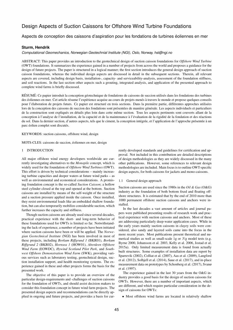
(Assume) foundation dimensions
Assess (cyclic) soil design profiles
Calculate foundation capacity
Design Basis: Soil layers and properties, Loads, etc.
Check installation
Calculate foundation stiffness and soil reactions
Assess serviceability
Geo
tech
nica
l Fou
ndat
ion
Des
ign
Iteration with other disciplines
Figure 1: Schematic presentation of the iterative and interdependent work-flow of suction caissons design
The consistency is achieved by an iterative design approach asillustrated in Figure 1. The geotechnical design of a suction cais-son foundation comprises 5 main activities: 1) Assessment of thecyclic soil properties for the given boundary conditions, i.e. loadconditions, foundation geometry, and soil layering and properties;2) Foundation capacity assessment for short- and long-term load-ing; 3) Prediction of the installation resistance and correspondingrequired suction pressure; 4) Serviceability assessment, i.e. short-and long-term settlement, displacement and rotation; and 5) Cal-culation of the foundation stiffness including corresponding soilreactions. The activities are interdependent and typically need tobe solved in an iterative manner in order to optimize the caissongeometry.
Furthermore the geotechnical design is embedded into a designloop interacting with other disciplines. The basis for the geotech-nical design will be continuously updated based on the results of
both the geotechnical analysis and other involved disciplines. Thestructural designer may update the properties of the caisson andthe sub-structure, the turbine manufacturer may update the (cyclic)loads, and the soil layering and properties may be complementedby updated field and laboratory test data, to name a few.
The workflow of the (geotechnical) design approach illustratedin Figure 1 is not very much different to that of any other foun-dation. However, it is important to be aware of the interdepen-dency, as this pose a natural limitation on the achievable optimiza-tion. A typical project comprises different phases; e.i. feasibil-ity study, pre-FEED1, FEED and Detailed Design. Each of thesephases can comprise one or several iteration(s). Current researchaims to solve some of the activities in an integrated manner (e.g.Krathe & Kaynia 2016, Page et al. 2016, Skau et al. 2017). Thatmeans it is tried to model the complete OWT in one analysis tocapture the interdependency. However, all parts, and in particularthe soil-foundation-system, is often represented in these analysisin a simplified way in order to limit the required calculation time.Thus an integrated analysis may not be suitable for an optimiza-tion, but can be very beneficial for other aspects, in particular forthe assessment of loads.
1.2 Interface between disciplines
The iterative design approach illustrated in Figure 1 requires aphysical interface between the different disciplines at which in-put, or output, respectively, is exchanged. There are in principaltwo types of information which need to be exchange between thegeotechnical and structural designer:
• The geotechnical designer gets loads and delivers back thecorresponding deformations, i.e. load-deformation curves.These curves are practically represented by lumped stiffnessvalues describing the response of the soil-foundation-systemin one point. The stiffness values are typically provided inmatrix form and can comprise of linear secant stiffness val-ues or non-linear tangential stiffness values.
• The structural designer requires for the caisson design dis-tributed loads and/or deformations acting on the skirts andlid. These distributed loads/deformations are often denotedSoil Reactions as they describe the response of the soil. Soilreactions can be provided as unit loads, total loads or linearsprings (i.e. Winkler-type springs).
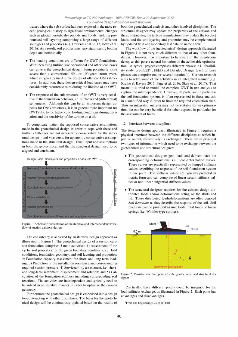
0.0 m
z
Symmetry axis caisson
GroutLid
0.0 m
Shaft2
1
3
r
Figure 2: Possible interface points for the geotechnical and structural de-signer
Practically, three different points could be imagined for theload-stiffness exchange, as illustrated in Figure 2. Each point hasadvantages and disadvantages.
1Front End Engineering Design (FEED)
46
Design Aspects of Suction Caissons for Offshore Wind Turbine Foundations
1. Traditionally, Point 1, located on the symmetry axis of thecaisson at mudline, is very often used. However, the structuraldesigner needs to establish loads at a point which is not con-nected to the structure. In order to do that, he needs to intro-duce a so-called super-element, connecting the structure withthe ground in this point. Given that the structure – in this casethe caisson lid and grout – is significantly stiffer than the soilfor the considered load level, simplified, linear elastic prop-erties can be assigned to the super element. If the flexibilityof the structure is considerably larger and a interaction withthe soil behavior may be expected, more complicated proper-ties need to be assigned to the super element. However, theseproperties are very difficult to assess, which may not be pos-sible. Experience from recent projects has shown, that boththe lid and skirt flexibility is important and an optimization ofthe caisson geometry is difficult, for which reason, Point 1 isnot recommended to be used in future projects.
2. Point 2, located at top of the caisson lid in the interface be-tween the shaft of the sub-structure and the caisson, has beenused in more recent projects. The advantage is, that Point 2is also often an interface for the structural design, as the de-sign of the caisson and sub-structure is often done separately.Loads are assessed by the load- or structural-designer usingintegrated analysis where only the sub-structure is modeled.The soil is therein often represented by set of springs in Point2. That means no super-element is required, but the geotech-nical designer needs to include the lid accurately in his anal-ysis.
The load-deformation response is complex, meaning that areasonable stiffness matrix describing the load-deformationof the soil-caisson-system will have both diagonal and off-diagonal components. However, most programs used for in-tegrated analysis cannot cope with a full stiffness matrix butcan take only the positive diagonal terms. That means that thesoil-foundation response can be only considered in a simpli-fied manner when using Point 2.
3. In order to overcome the shortcoming of using a simplifiedstiffness matrix in the structural analysis, the stiffness matrixcould be provided for the so-called decoupling point, whichis illustrated in Figure 2 by Point 3. The decoupling point canbe assessed in the stiffness analysis as described in Section 7,and is characterized by the fact that incremental horizontal,vertical or moment loads yield only displacements or rota-tions in the corresponding loading direction. That means thatthe stiffness matrix comprises only positive diagonal terms.If the geotechnical designer includes in the stiffness analysisthe caisson with its correct properties, and applies the loads inPoint 2, the structural designer can use a rigid super elementconnecting Point 2 with Point 3 and apply the stiffness matrixin the integrated analysis in Point 3. Though Point 3 seemsto be the most appropriate point for the interface, the problemis, that the location of the decoupling point is not constant butdepends on the load-level, combination of load componentsand load-deformation response.
Based on experience from recent projects, it is recommendedthat the structural designer provides the caisson model and theloads in Point 2, and the geotechnical designer delivers back a stiff-ness matrix in Point 2 and Point 3 as well as the coordinates ofPoint 3.
In Section 7 is introduced the concepts of a global model.Though this model is a considerable improvement as both the sub-structure, caisson and soil is modeled, it does not overcome the
above described problem of finding an appropriate interface point.The structural designer will still need stiffness values at the bottomof the sub-structure.
In principal, stiffness values and soil reactions could be estab-lished from the same analysis as they are actually describing thesame response. However, the extraction of soil reactions from FEanalysis is difficult and very sensitive to the modeling technique,element-type and -size. As the soil reactions are only used for thecaisson design, but neither for the load assessment nor the designof the sub-structure, it has been found most appropriate to establishreasonable ranges for the distributed loads acting on the skirts andlid based on empirical considerations.
2 DESIGN BASIS
The design basis is the input to the geotechnical design before anyinterpretation or processing is done. It comprises soil properties,loads, structural properties, guideline requirements, and other rele-vant boundary conditions such as weight- and size-limitations dueto logistical considerations.
2.1 Site and soil parameters
The loading regime acting on a suction caisson requires specialattention with respect to the soil parameters used in the design.The impact of cyclic loading on the soil strength and stress-strain-behavior needs to be quantified by a thoroughly planned laboratorytesting program of all relevant soil layers. The following list out-lines the recommended minimum site- and soil-investigation pro-gram to establish the required soil-profiles and -parameters:
• From a geotechnical perspective, a geophysical survey is rec-ommended to identify the number and depth of the soil layersat the OWT location(s). The geophysical survey should pro-vide an overview of the soil profile variability at a location,which is in particular relevant for multi-legged sub-structureshaving three or more caissons. In some recent projects, twosurveys have been conducted. In a first survey the completeoffshore wind farm was screened, whereas in a second surveyhigh resolution 3d seismic scans of the shallow soil has beenperformed. The advantage of the latter survey is, that it al-lows to find also small boulders, which can be critical for theinstallation.
• Minimum one seabed Cone Penetration Test (CPT) per loca-tion with a minimum investigation depth za, measured fromthe skirt tip, where za is the maximum of
– the depth below the caisson where the additionalstresses ∆σ′v due to the permanent weight of the struc-ture does not exceed 15% - 25% of the in-situ stressprior to the installation of the caisson. Assuming a loadspread angle of 1:3, a submerged foundation weight be-tween 5 to 7MN, a caisson diameter between D = 8and 10m, a submerged unit weight of the soil of 10 kN
m3 ,and a skirt depth of s = 0.6 · D, the required depths+ za (measured from mudline) varies between 15 and20m.
– the depth of the governing failure mechanism in a bear-ing capacity analysis, which is a function of the caissondiameter D, the number of footings and distance of thelegs, and the loading regime. A rotational failure is ex-pected for mono-caissons, whereas a compression fail-ure is expected for caissons supporting a jacket. In bothcases, the depth measured from the skirt tip level is less
47
Proceedings of TC 209 Workshop - 19th ICSMGE, Seoul 20 September 2017Foundation design of offshore wind structures
than the caisson diameter, given that there is no inter-action between the footings of multi-legged structures.For the dimensions indicated above, the required depths+ za (measured from mudline) varies between 10 and14m.
Even though, neither combined deep failure mechanisms ofmulti-legged structures, nor exceptionally high weights, havebeen observed in past projects, it is recommended to checkin the FEED study, whether the values given above are notexceeded. That means, it needs to be ensured that the ad-ditional stresses are not larger, nor the actual failure modegiving the lowest foundation capacity reaches deeper than as-sumed. If the required investigation depth cannot be achievedby the seabed CPT, complementary downhole CPT should beperformed.
At sites and turbine locations where highly variable soil con-ditions are expected, several CPTs should be conducted.
In general, it is recommended to perform the CPTs outside theactual caisson location, to avoid open holes which will poten-tially affect the caisson installation and may even prevent thecaisson to reach the target penetration depth.
• Sufficient boreholes at the site in order to extract samples ofall relevant soil units. Number and locations of the boreholesshould be selected based on the review and interpretation ofthe geophysical and CPT data, preferable on basis of a groundmodel (e.g. Forsberg et al. 2017)
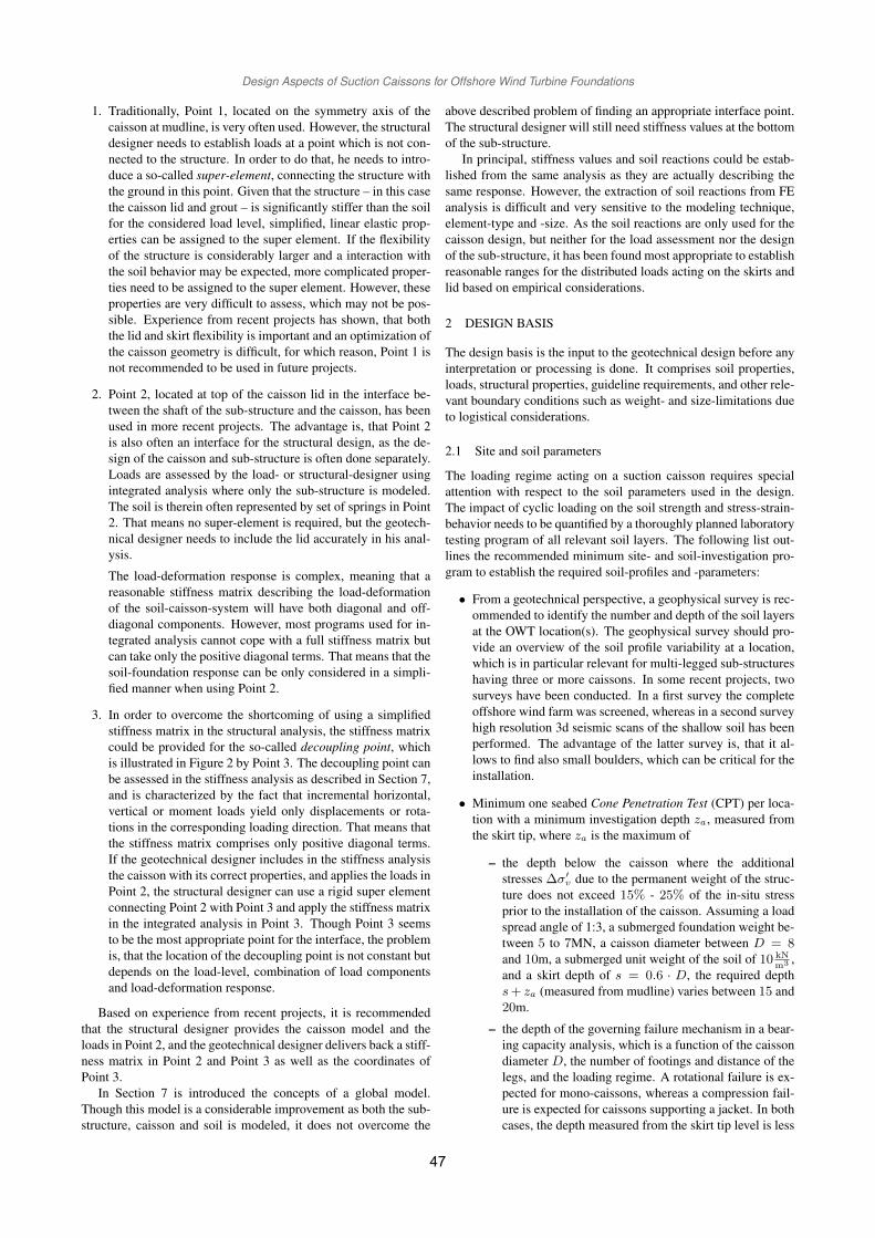
• Laboratory tests of all relevant soil layers within the CPTdepth. Andersen et al. (2013) provide a comprehensive listof required parameters for various foundation concepts. Asummary of parameters for suction caissons is listed in Ta-ble 1. The crosses in brackets indicate parameters, which are,according to the author’s experience, somewhat less relevant.
In order to determine the required parameters, drained andundrained, monotonic and cyclic DSS, triaxial compressionand triaxial extension tests need to be performed. Further, oe-dometer tests, bender element tests, and interface tests shouldbe included in the testing program. For layers with fewdecimeter thickness, triaxial tests may be omitted. The num-ber of tests depends on the loading conditions, available datafrom previous investigations at similar material, and the ap-plied design methodologies. A representative set of labora-tory tests per soil layer may comprise
– 2 oedometer tests,
– 1 monotonic undrained DSS test and 1 monotonicundrained triaxial compression test, as well as corre-sponding drained tests when testing sands,
– 3-5 cyclic undrained DSS tests,
– 4-6 cyclic undrained triaxial tests
In addition, other tests such monotonic as drained triaxial ex-tension, or resonant column tests may be conducted wherenecessary. Of particular importance is the soil-skirt interfacestrength. It may be best represented by a remolded DSS testconsolidated to a stress equivalent to the lateral in-situ stressafter installation. The stress level needs to be estimated. Rea-sonable stress ratios may be 0.5 and 1.0 times the verticalin-situ stress σ′v = γ′soil · z. Larger values may be less likelydue to set-up effects and arching, but may need to be decidedproject specific.
Table 1: Recommended soil data for suction caisson design (afterAndersen et al. 2013)
Soil parameter Clay Sand
Frictional characteristicsPeak drained friction angle, ϕ′ x
Cyclic data (triaxial and DSS)Undr. shear strength, τf,cy = f(τa, τcy, N) x x
Pore pressure, up = f(τa, τcy, N) (x) x
up = f(τcy, logN) for τa = τ0, (x) x
Stress strain data, γa, γp, γcy = f(τa, τcy, N) x x
γcy = f(τcy, logN) for τa = τ0 x x
Damping x x
Consolidation characteristics, intact soilPreconsolidation stress (and OCR) x x
Un- and reloading constrained moduli x x
Permeability, k (x) x
Remoulded soil data x
Sensitivity, St x
Undrained shear strength, sDSSu x
Cyclic undrained shear strength, τf,cy x
Constrained modulus (x)
Permeability (x)
Thixotropy (x)
It is important to perform the tests at a stress and densityor OCR, respectively, representative for the expected in-situconditions before and after installation. Three zones need tobe distinguished; inside the caisson, outside the caisson, andbelow the caisson. While the soil state outside the caisson willbe less affected by the installation, the soil at the inside mayundergo considerable shearing, which will affect the densityand stresses. The soil below the caisson will be less affectedby the installation, but the weight of the OWT will yield anincrease of the vertical effective stresses (with time).
In addition, index parameters such as relative density Dr ,plasticity coefficient Ip, water contentw, and grain size distri-bution should be determined. These are in particular relevantin an early stage of the project for the feasibility study andpreliminary sizing, where not all laboratory tests have beeninitiated yet, and where strength and stress-strain-behaviourhas to be assessed based on correlations using index data andCPT soundings. Andersen (2015) proposes a comprehensiveset of correlations, which can be used as a first estimate of theexpected soil parameters.
48
Design Aspects of Suction Caissons for Offshore Wind Turbine Foundations
In addition, information of scour development and/or scour pro-tection is required. Type, thickness, submerged weight, and infor-mation on the stability of the planned scour protection need to beconsidered in the geotechnical analysis.
2.2 Loads
The geotechnical designer needs to consider two different loadsets. One set is required for the actual geotechnical design, i.e.capacity and serviceability analysis. The other set is used in theload-stiffness iteration (outer loop in Figure 1). Some load casesmay be included in both sets. But in general, the loads cases aredifferent in both sets, since the governing design-loads and -criteriaare typically different in the structural and the geotechnical design.That means each discipline has to identify the relevant load cases,and need to define them such that everyone involved in the designprocess has a common understanding. Since this is a very criticalaspect of a successful project, a load document should be prepared,which is continuously updated. This has been proven beneficial inmany projects.
Most design guidelines distinguish between loads for the Ul-timate Limit State (ULS), Serviceability Limit State (SLS), andFatigue Limit State (FLS)2. ULS loads are required by both thegeotechnical and the structural designer. However, SLS loads aremainly relevant for the geotechnical analysis, whereas FLS loadsare mainly relevant in the structural analysis. All load cases areassessed by the load or structural designer, and the geotechnicaldesigner need to provide input to these.
Identifying or defining the required loads needs an experienceddesigner. A reasonable starting point for the capacity analysis is tolook at the load cases comprising the maximum amplitudes; thatmeans maximum compression, tension, moment, etc. The maxi-mum load amplitudes often adhere a load event which is embeddedinto a cyclic load history, which can be a storm for example. TheGerman Bundesamt für Seeschifffahrt und Hydrographie (BSH) in-troduced in the standard BSH (2015) a 35-hrs design storm basedon a composition of the Design Load Case (DLC) 6.1 proposed inthe IEC standard IEC (2009). This cyclic event shall be applied toassess the cyclically (degraded) soil strength, which is to be usedin the (subsequent) geotechnical analysis. Practically, this eventhas also been also applied outside Germany, due to the lack of al-ternatives, since the DLC’s defined in the IEC standard are 10 or60 minute long load-time series, which cannot be directly used ina geotechnical design.
In more recent projects, where turbines with larger capacitywere considered, it has been found that also other events can becritical, such as an (emergency) shut-down at relative high wind-speeds. In the event of an (emergency) shut-down, the OWTswings and the load spectrum corresponds to a damped vibration.Depending on the degree of damping, which affects the decay rate,subsequent load cycles with smaller amplitudes can be critical dueto the cyclic degradation of the soil, induced by the previous largerload cycles. Another event found critical for the foundation ca-pacity analysis of multi-legged structures is the prolonged tensionload case, which typically occurs during operation of the turbine athigh wind speeds.
In addition to the in-place loads, there may be further situationswhich needs to be considered in the design. These can be loadcases during installation, maintenance, and decommissioning ofthe OWT.
2The author questions the appropriateness of the expression limit state in this con-text. However, since it is widely used, it is – due to convenience reasons – also adoptedin this contribution.
More complicated is the identification of the load cases whichshould be used for the serviceability analysis. Two scenarios haveto be distinguished; a maximum deflection and rotation during asevere load event, and accumulated average long-term deforma-tion and rotation. The peak deflection may be assessed using theloads used in the capacity analysis. For assessment of the longterm deformations and rotations, cyclic loads are required. Ide-ally, all loads during the lifetime of the OWT should be consideredin chronological order. However, as this cannot be applied in ageotechnical analysis, simplified load histories are required.
It can be supposed that large cyclic load amplitudes will con-tribute most to the accumulated deformations and rotation. Thusfocusing on a series of storm events may be a reasonable simpli-fication. One option could be to use the 35-hrs design storm andassuming a Gumble distribution to extrapolate the peak amplitudesof other storms with different return periods. The accumulated av-erage displacements and rotations can be calculated for each scaled35-hrs design storm separately and then superimposed dependingon the expected number of occurrences of each storm during thelifetime of the OWT.
The main challenge is to derive from the load-time-series theactual load amplitudes and corresponding mean values, and num-ber of occurrences, both of the maximum- and the cyclic-loadevents. Most commonly the so-called rainflow-counting-algorithmis applied. Though this algorithm is widely used in structural fa-tigue analysis, it is important to be aware of its limitations:
• It is assumed that the loads are independent, meaning that theorder of load cycles is not important.
• The information of the load frequency, that means the cyclicperiod, gets lost.
• Since only the peak values are counted (that means actuallyhalf-cycles are counted), no information can be directly de-rived of the actual corresponding mean load.
Depending on the soil type, drainage properties and boundaryconditions, these information can be crucial. Thus, if these infor-mation would need to be considered, other counting methods maybe applied where possible; for example the method proposed byNorén-Cosgriff et al. (2015). They apply high- and low-pass filtersand determine the amplitude of each half-cycle from adjacent max-ima and minima, which belong to the same load cycle. In addition,the proposed method keeps track of the corresponding average loadand may also keep the information of the load period (frequency).The authors compared their method with the rainflow-counting-algorithm and showed that the calculated cyclically degraded soilstrength using the example of a normally consolidated clay can besignificantly different.
Cyclic load histories are often provided in from of a MarkovMatrix comprising cyclic load amplitudes and corresponding meanload value as well as number of occurrences. Since these are of-ten established using the rainflow-counting-algorithm, it is recom-mended that the geotechnical designer reviews also the originalload-time-series from which the Markov Matrix has been estab-lished. This in particular applies to the load-time-series compris-ing the maximum load values used in the geotechnical capacityanalysis. The load cycle yielding the maximum load values maysometimes appear to have a considerable offset from the rest of thecyclic loads history and it requires geotechnical judgment to de-cide on the load cycle which the soil actually experience. But alsoa critical review of the mean load value is important, as the soil be-haves essentially different symmetric and asymmetric cyclic loads.
49
Proceedings of TC 209 Workshop - 19th ICSMGE, Seoul 20 September 2017Foundation design of offshore wind structures
It is recommended that permanent and environmental loads areprovided separately, and both as characteristic values, as occasion-ally, different partial safety factors need to be applied to the differ-ent load components in the geotechnical and structural analysis.
2.3 Structural properties
As outlined in Figure 2, it may be important to include structuralcomponents in the geotechnical analysis. With increasing com-plexity of the structural model, the stability and accuracy of nu-merical analysis may be quickly challenged. Thus, if structuralmodels shall be included in a geotechnical analysis, they may besimplified as appropriate. Beam and plate elements should be pre-ferred over continuum elements. Structural components such asstiffeners and stays may be omitted where possible.
For capacity analysis, a rigid structure may be assumed, as thethe strength and stiffness of the soil at failure is several magnitudessmaller than the strength and stiffness of the structure, given thatthe yield stress of the caissons material is not exceeded at any time.
For installation purposes, the properties of the skirts are of fun-damental importance and need to be considered in the penetrationanalysis as accurate as possible. In general, the skirt tip resistanceincreases with increasing wall thickness. If stepped skirts are con-sidered, i.e. where the skirt wall thickness varies over the height,the skirt friction may be affected considerably, which also will af-fect the in-place behavior. It is also important to consider compart-ments3 and stiffeners in the penetration analysis if present.
2.4 Guidelines and safety factors
A dedicated standard or guideline for the design of suction caissonsfor OWT applications does not exist. In the absence of such a doc-ument, other non-dedicated standards and guidelines need to be ap-plied in the design. This requires to define a code hierarchy, wherein general national standards rank highest, followed by offshorewind related standards as well general offshore standards, and fi-nally other standards, guidelines and publications, which rank low-est. Some examples are presented in the following.
The IEC has proposed a series of documents addressing the par-ticular design aspects of onshore and offshore wind turbines. Forthe load assessment and corresponding partially load factors, typi-cally IEC standard 61400-3 is applied (IEC 2009). Other standardspublished by the IEC consider structural and geotechnical designaspects. However, these documents are so generally formulated,with respect to geotechnical requirements – and in particular suc-tion caisson design – that other standards need to considered.
To the author’s knowledge, all countries where OWTs areconsidered, have own national standards for geotechnical design.However, since these standards originate form onshore design re-quirements, the application of the recommended methods and pro-cedures to offshore structures can be critical. Thus, some countriesare in the process of establishing national standards particularly forOWTs. This has been done by the German BSH for example. TheUS Bureau of Ocean Energy Management (BOEM) and the Ger-man DIN are also working on corresponding documents.
As most OWTs need to be certified due to financial and insur-ance reasons, some certifiers have published their own guidelines,which are frequently used in the design. Most relevant is the DNVGL standard 0126 (DNV-GL 2016). This document provides valu-able recommendations and includes also a section on suction cais-sons. However, it is very generally formulated and neither particu-lar methods nor procedures are proposed.
3Compartment mean that the caisson lid area is divided into different cells
Selecting appropriate safety factors for the design is difficult.Solely the DNV standard proposes a consistent safety concept forcapacity analysis considering the particular offshore conditions. Ingeneral, the strength of the soil shall be reduced or carefully es-timated for capacity and serviceability analysis. However, for theinstallation analysis, a higher strength is more critical, which is notconsidered in any standard. Sturm et al. (2015) proposes safetyfactors for installation analysis of suction caissons in sand, whichwere established based on probabilistic analysis. Similar type ofanalysis may be performed for other design aspects. No safetyfactors should be applied in the serviceability-, stiffness-, and soilreaction-analysis as detailed in the corresponding sections.
Due to the lack of long-term experience, it is recommendedto consider a comprehensive monitoring system as part of the so-called observational method.
3 CYCLIC STRESS-STRAIN BEHAVIOR
The loading condition of an OWT is of inherent cyclic nature.Thus, all components including the soil, need to be designed ac-cordingly. The general supposition is, that cyclic loading yields adecrease of strength and stiffness, often denoted as cyclic degrada-tion. This applies to all soil types and foundation concepts.
A number of authors have proposed methods for assessing theeffect of cyclic loading on the suction caisson foundation response.Therein two main approaches are followed; an empirical approachand an analytical/numerical approach.
• The empirical approach is typically based on model testwhere the soil-foundation system is considered as one entity.The caisson is subjected to cyclic loading and the responsein the loading point is measured. The actual behavior of thestructure and soil is not considered separately, hence it is aphenomenological approach. The results can be presented ininteraction diagrams4 or failure envelopes in the HVM space,where HVM is the horizontal, vertical, or moment load com-ponent, respectively. Failure envelopes allow a more detaileddescription of the foundation response compared to interac-tion diagrams. In addition, a failure envelope diagram canbe extended to describe the actual load-displacement behav-ior by introducing a stack of HVM envelopes to which thecorresponding displacement components are assigned. Sincethese diagrams are based on interpolation of some few datapoints, they are essentially empirical. Many, so-called macro-elements, are based the empirical approach. Some Macro el-ements are mathematical complex and can describe very de-tailed the load-deformation behavior of a caisson subjectedto general cyclic loading. A number of authors have devel-oped macro-elements for suction caissons, (e.g. Nguyen-Sy2005, Nguyen-Sy & Houlsby 2005, Salciarini & Tamagnini2009, Salciarini et al. 2011, Foglia et al. 2014, Skau et al.2017). Macro-elements are well suited in integrated analysisfor structural design and load assessment.
• In the analytical/numerical approach the response of thesoil-foundation system is assessed by modeling the actualsoil-structure interaction under consideration of the structuralflexibility and stress-strain-behavior of the soil. This requiresa detailed description of the skirt-soil- and lid-soil-interfacebehavior. In an analytical approach, the distribution of aver-age and cyclic loads – or actually stresses – along the skirtsneed to be assumed, whereas the distribution is automaticallycalculated in a numerical approach. The assessment of the
4Similar to diagrams used for cyclic axially loaded piles
50
Design Aspects of Suction Caissons for Offshore Wind Turbine Foundations
cyclic stress-strain behavior and strength of the soil needs tobe described by using appropriate soil models. The analyt-ical/numerical approach is well suited for the geotechnicalsizing of the caisson, but may also be used for assessmentfor the serviceability and calibrating of the input parametersto a macro-element.
NGI has developed a method for describing the behavior ofcyclically loaded soil elements using so-called cyclic contour di-agrams. The method, originally proposed in the early 70th, whichwas continuously developed further, has been presented in a nu-merous publications; the most recent and comprehensive one isthe article by Andersen (2015). Cyclic contour diagrams span a3-dimensional space and provide a general relation between aver-age and cyclic shear stresses and corresponding average and cyclicshear strains as function of number of applied cycles. Diagramsare established for one soil type and density or OCR, respectively.One complete set of 3d-diagrams for one soil unit comprises typi-cally of 4 diagrams; 1 strain and 1 pore pressure diagrams for tri-axial and DSS conditions, respectively. In many practical applica-tion cases, only some representative 2-dimensional cross-sectionsof the 3-dimensional space are required. This simplifies the ap-proach and reduces the number of cyclically laboratory tests. Theselection of appropriate cross-sections requires some experienceand assumptions.
In combination with a cyclic load history, the cyclic contour di-agrams can be used in the so-called cyclic accumulation procedure.The cyclic degradation due to the cyclic loading is calculated andthe effect can be expressed by the so-called Equivalent number ofcycles (Neq).
As cyclic contour diagrams provide a relationship betweenstresses and strains, but the cyclic loads are given as forces, as-sumptions on the load transfer and stress distribution has to bemade, which is best done using the Finite Element Method (FEM).This is in particular the case where complicated boundary condi-tions, soil layering and drainage conditions are analyzed, which isin general the case for suction caissons for OWTs. NGI has im-plemented the cyclic accumulation procedure using cyclic contourdiagrams in an FE code. Jostad et al. (2014) present the procedurefor fully undrained conditions during the considered cyclic loadhistory (UDCAM)5, whereas the procedure for partially drainedconditions (PDCAM)6 is presented by Jostad et al. (2015b). Thecyclic accumulation is done for each integration point. The ad-vantage of using the FEM is, that the stress redistribution is con-sidered accurately and continuously updated if relevant, and thatstrain continuity is ensured. Furthermore, a output of such ananalysis is not only the cyclic stress-strain behavior and degradedstrength and stiffness, but also the accumulated displacements androtations, which are required for the serviceability analysis.
Though the soil-structure interaction is modeled in detail (nu-merical approach), the description of the soil behavior using cycliccontour diagrams is an empirical approach.
An example of a PDCAM analysis of a suction caisson sub-jected to a combination of vertical and horizontal cyclic loading isshown in Figure 3. A suction caisson with 8m diameter and 6mskirt length in a homogeneous soil deposit with an average soilpermeability of k = 1 · 10−5 m
sis modeled. At the peak phase of
an 35-hrs design storm according to BSH (2015), the soil at skirttip level accumulates considerable excess pore pressure. Due tothe symmetric soil and load conditions the predicted pore pressurefield is also almost completely symmetric.
5UnDrained Cyclic Accumulation Model6Partially Drained Cyclic Accumulation Model
Figure 3: Finite element analysis of a suction caisson subjected to com-bined vertical and horizontal cyclic loading using the NGI soil model PD-CAM. The contour plot shows the excess pore pressure at the end of thepeak phase during a 35-hrs design storm.
4 FOUNDATION CAPACITY
The foundation capacity needs to be ensured for all possible loadcombinations. Two main load scenarios should be distinguished,which are detailed in the following.
4.1 Short-term loading
Short-term loading is characterized by a loading duration beingso short that the soil behaves essentially undrained, meaning thatthe soil response depends on the undrained shear strength only. Insandy soils, the caisson may mobilize considerable suction belowthe lid and negative pore pressure in the soil, causing an increase inmean stresses and hence higher shear strength. Due to the shallowwater depth at typically OWT sites, particular attention requiresthe cavitation limit. The cavitation limit cannot be exceeded by thesuction or negative pore pressure, respectively. That is in partic-ular important to consider when deriving the shear strength fromlaboratory tests where considerable back-pressures may have beenapplied, as these tests can potentially exceed the maximum achiev-able pore pressure and hence strength compared to the actual in-situ conditions. The theoretical cavitation limit pcav,max in a soilelement is the sum of, the depth z of that element below mudlineplus the water depth ws, multiplied with the unit weight of waterγw = 10 kN
m3 , and the atmospheric pressure patm = 100kPa, viz.
pcav,max = (z + ws) · γ′w + patm (1)
At NGI, the short-term capacity analysis is often done using atotal stress approach. Figure 4 shows a potential failure mecha-nism of a suction caisson under combined compression and mo-ment loading. The undrained strength in the failure zone is de-scribed by the strength measured in undrained DSS tests, or in atrixial tests where different Total Stress Paths (TSP) are followed.Cyclic contour diagrams can be used for assessing correspondingcyclic shear strength values.
Figure 5 illustrates the four main different total – and corre-sponding effective – stress paths, using the example of a mediumdense to dense sand specimen consolidated to a stress state ofk =
σ′hσ′v
= 0.5 at a vertical effective stress of σ′v = 200kPa.The difference between the TSPs is the way the shear strength hasbeen applied. For path 1 and 6 the cell pressure in a triaxial test hasbeen decreased or increased, respectively, whereas for path 4 and 2the vertical pressure has been increased or decreased, respectively.
51
Proceedings of TC 209 Workshop - 19th ICSMGE, Seoul 20 September 2017Foundation design of offshore wind structures
0.0 m
z
HV M
TSP 1
DSS
TSP 2
TSP 4DSSDSS
TSP 6
Filter layer (optional)Grout
Figure 4: Possible failure mode of a caissons subjected to combined com-pression and moment loading
In addition, the total and effective stress path in direction 4 for aspecimen consolidated to σ′v = 20kPa is shown.
-300
-200
-100
0
100
200
300
400
0 50 100 150 200 250
q [
kPa]
p’ [kPa]
TSP4ESP4TSP1ESP1TSP6ESP6TSP2ESP2
CSLCSL
TSP4 LSESP4 LS
Figure 5: Total and Effective stress path in trixial tests where the shearstress is applied in different ways.
From Figure 5 becomes apparent that the soil strength of a sandspecimen for a given initial density and stress state is dependingon the loading path. The difference between the total and effec-tive stress for the different paths equates the corresponding porepressure. The maximum negative pore pressure cannot exceed thecavitation limit. Whether the NGI method or any other method isapplied, it is important that the dependency of the stress path andthe cavitation limit is considered accurately when assessing the soilstrength profile.
The stress path dependency is equally relevant for clay speci-mens. In additon, due to the viscosity of clays, the dependencyof the shear strength on the shear rate needs to be considered.The shear rate in laboratory tests may be different compared to in-situ loading rate for short-term loading, meaning the shear strengthmay need to be corrected accordingly.
The capacity of suction caissons to short-term loading is es-sentially governed by the load combination, that means horizon-tal, vertical and moment loading. As illustrated in Figure 1, thedesign basis, including the loads, is continuously updated. Fig-ure 6 shows the dependency of the ULS loads on the rotationalstiffness of a suction caisson at the example of a multi-legged sub-structure. The loads of a leg in compressions, are normalized withthe reference loads provided in the 1st iteration. The predictedcorresponding rotational stiffness – also normalized – is shown atthe abscissa where all load components are crossing. Though theglobal loads acting on the OWT are constant, the local loads canvary considerably depending on the response of the caisson. Thehigher the rotational stiffness, the lower the vertical and torsionalloads. Similar effects, but less pronounced is found for the other
0
50
100
150
200
250
0.001 0.01 0.1 1 10 100 1000
No
rm.
loa
ds F
x/F
x,r
ef, F
z/F
z,r
ef, M
y/M
y,r
ef [%
]
Norm. rot. stiff. kϕϕ/kϕϕ,ref [-]
Fx
My
Mt
Fz
Figure 6: ULS loads as function of the rotational stiffness of caisson sup-porting a three-legged jacket.
stiffness components.
50
100
150
200
0.001 0.01 0.1 1 10 100 1000
No
rm.
Fo
S
[%
]
Norm. rot. stiff. kϕϕ
/kϕϕ,ref [-]
Figure 7: Normalised Factor of Safety (FoS) as function of the appliedloads shown in Figure 6
The effect of the load combination shown in Figure 6 on thecaisson capacity is shown in Figure 7, where the normalized Fac-tor of Safety (FoS) is plotted on the abscissa. As it may be expectedfrom conventional bearing capacity analysis, the normalized FoS islower for larger moments, that means for a rotational failure mode.That applies also to a mono-caisson foundation, which is essen-tially subjected to environmental horizontal and moment loadingonly.
In offshore foundation design of multi-legged jacket structures,it is often assumed that the rotational stiffness of a foundation atULS loading is considerably lower than the rotational stiffness ofthe corresponding leg of the sub-structure. Hence, the local mo-ment loading at failure may be omitted in the capacity analysis.However, the relatively high jackets stiffness can be an issue forthe fatigue design of an OWT, as the goal is, that the first eigen-mode shall be in the range between 1P and 3P; e.g. typically be-tween 0.25 and 0.35 Hz for turbines with 6 to 8MW. Thus, thestructural designer tries to make the jacket more flexible, meaning,that omitting the local moment may be too optimistic.
To complicate matters, the local load components at a leg of ajacket do not scale proportionally with the global load amplitude,even though the global loads may be applied linearly increasing.Thus, the ULS load components provided in the design basis may
52
Design Aspects of Suction Caissons for Offshore Wind Turbine Foundations
not be scaled proportionally with a load factor. However, as thesoil will be always softer than the jacket leg in rotation when beingat failure, overestimating the local moment may yield lower FoS asshown in Figure 7. Nevertheless, it is recommended to check theFoS for differently scaled local loads, that means lower load factorapplied to the local moment and a larger load factors to the vertical,horizontal and torsional load components. For mono-caissons, aredistribution of the local loads is not expected and the same loadfactor should be applied to all load components.
For suction caissons subjected to tension loading, the same con-siderations discussed above apply. The TSP strength used in theanalysis need to account for the different loading and hence stressconditions.
Gapping at the outside of the caisson may need to be consid-ered in the capacity analysis, if previous load conditions or steppedskirts may have generated a gap. Due to the short-term loading, thedrainage time may not be sufficient to generate a new gap duringthe considered load event. This depends of course on the load com-bination and soil type and may need to be checked.
Of particular importance is the scour development and scourprotection. The stress and density state of the soil can be consid-erably affected, which can have an impact on the foundation ca-pacity. Whether to include or omit the effect of a scour and scourprotection should be discussed with the operator, as the presump-tion of a permanent scour protection may require more frequenton-site inspections, which can have an impact on the Operationaland Maintenance (O&M) costs.
4.2 Long-term loading
Suction caissons have considerable capacity under short-term load-ing conditions. However, the resistance to long-term loading, canbe very low, as the possibly mobilized suction may dissipate. Thisis in particular relevant for suction caissons supporting a jacketstructure. During operational load cases the caisson(s) may expe-rience considerable tension loading, which can last for hours oreven days. The tension capacity of suction caissons is a functionof the skirt wall friction and the soil permeability.
For caissons in clay the soil permeability will be low, meaningthat the capacity can be calculated similar to the long-term capac-ity, but the shear strength needs to be reduced to account for theslow loading rate. In the absence of suitable tests, the decrease inshear strength may be estimated using
su,slow = su,ref ·(γ̇slowγ̇ref
)Iv(2)
where the su,ref is the shear strength measured in the laboratoryat a shear rate of γ̇ref . γ̇slow is the shear rate representative for theconsidered load case. Iv is a viscosity coefficient which typicallyvaries between 0.03 and 0.07 for a silty or fat clay, respectively(Leinenkugel 1976). Iv can be determined with Equation 2 froman undrained static laboratory test, where the shear rate is varied.
If previous load cases, structural boundary condition or anyother causes may have generated channels or gaps at the outsideand inside of the caisson in the clay, only the skirt wall friction canbe considered in the tension capacity analysis.
For caissons in sand, the soil permeability is considerablyhigher, meaning that a continuous flow of water from the outsideto the inside can be expected, given that the tension load exceedsthe resistance calculated by integrating the fully drained skirt wallfriction over the skirt area at inside and outside of the caisson. Inthis case, the capacity is the sum of the drained skirt wall fric-tion at the outside, a reduced drained friction at the inside – due
to the upward flow reducing the effective vertical stresses – and asmall suction pressure below the lid, which is required to maintaina constant flow. The friction capacity needs to be further reducedto account for the relative vertical movement of the caisson, whichreduces the vertical stresses in the soil and hence the shear stressesin the soil-skirt-interface.
The difficulty is to decide upon the load and resistance factorswhich shall be applied. If a load case can potentially cause a failureof the structure, the full load and resistance factors according to theconsidered standard should be applied. However, if the loads for aconsidered load case can be controlled, for example by the turbineoperation, the load factors may be reduced somewhat to acknowl-edge for the reduced uncertainty in the actual load amplitude. Butalso the failure mechanism may justify to apply somewhat lowersafety factors. In case of a suction caisson in sand subjected tolong-term tension loading, the structure may not experience a sud-den failure, but may be pulled out gradually. If reduced load andresistance factors are applied, the serviceability needs to be en-sured at any time, and an appropriate monitoring system should beinstalled, in order to apply the observational method. In addition,mitigation measures need to be prepared.
As the loading conditions of OWTs is of essentially cyclic na-ture, also the long-term tension loading is actually a cyclic loadcase. Thus, an appropriate cyclically degraded shear strength pro-file and corresponding stress-strain response need to be used. Forthat purpose assumptions need to be made on the distribution ofthe average long-term tension load and the cyclic amplitude. De-pending on the considered load case, it may be assumed that theskirt-soil-interface at the outside of a caisson in clay may take thecyclic component and the soil below and inside the caisson maytake the average component. Where this distinction should not bepossible, an equally degraded strength profile may need to be as-sumed.
As the cyclic load components have relatively short period, thesoil response of a caisson in sand will be essentially undrainedto this component only. Thus, for a caisson in sand, the capac-ity needs to be checked for at least two cases; the resistance tothe average tension load, and the resistance to combined cyclicand average load using an appropriate cyclic shear strength pro-file. When using the NGI framework based on cyclic contour dia-grams, the strength and stress-strain response can be derived fromdiagrams where the average shear stress was applied drained in thecorresponding laboratory test. Further information can be found inAndersen (2015).
The same considerations made for the short-term bearing ca-pacity analysis on whether to include or to omit the effect of scouror scour protection, applies to the long-term bearing capacity anal-ysis as well.
5 INSTALLATION
The installation is considered by many as one of the most chal-lenging aspects of suction caisson application. However, experi-ence from actual installations has demonstrated that installationin many different soil types and profiles is feasible. Moreover,the predicted penetration resistance and hence the required suctionpressure agrees often reasonably well with the actual measuredvalues (e.g. Sparrevik 2002, Colliat et al. 2007, Aas et al. 2009,Langford et al. 2012, Solhjell et al. 2014, Saue et al. 2017).
The governing mechanisms are well understood and several au-thors have developed calculation methods. Most methods can beapplied in uniform and homogeneous soil conditions or soil pro-files with perfectly horizontal layering. A general discussion of the
53
Proceedings of TC 209 Workshop - 19th ICSMGE, Seoul 20 September 2017Foundation design of offshore wind structures
installation process and calculation methods is presented in Sub-section 5.1.
All existing calculation procedures have limitation, and thereare a number of aspects which need particular attention during theactual installation, since they cannot be considered by the existingcalculation models. Some of the most relevant aspects are pre-sented in Subsection 5.2. Possible mitigation measures are dis-cussed in Subsection 5.3.
5.1 Calculation methods
The often reasonably accurate predictions of the penetration resis-tance and hence required suction pressures is a result of extensiveresearch in this field. A number of authors have proposed meth-ods for calculating the penetration resistance and required suctionpressure in both clay, silt and sand layers; particularly noteworthyare the models proposed by Houlsby & Byrne (2005a,b), Andersenet al. (2008) and Senders & Randolph (2009). These are based onmodel tests, field tests and prototype installations.
The penetration resistance is a function of the skirt tip resis-tance Qtip and the skirt wall friction Qwall. Qtip may be esti-mated using a bearing capacity based approach or correlations withmeasured CPT resistances. Qwall is a function of the skirt-soil-interface strength τfric and the effective skirt wall area. τfric canbe assessed by means of laboratory tests, such as DSS tests or ringshear tests. Alternatively, τfric can be estimated using correlationswith measured CPT resistances.
If the total penetration resistanceQ = Qtip+Qwall exceeds thesubmerged weight of the caisson and sub-structureW ′ = W ′cais.+W ′substr., an additional driving force needs to be applied in orderto penetrate the caisson to the required Target Penetration Depth(TPD). This is done by applying a relative under- / suction-pressurepsuc at in the inside of the caisson. The additional driving forceis calculated by integrating the applied suction pressure over thehorizontally projected area Asuc to which the pressure is applied.The maximum achievable penetration depth is reached when thetotal resistance Q exceeds the driving forces W ′ + psuc ·Asuc.
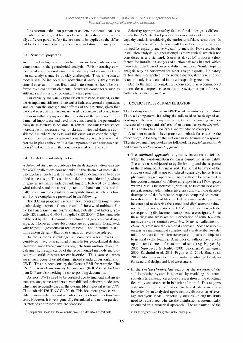
Two main scenarios need to be distinguished; an undrainedpenetration and a drained penetration. A penetration is undrainedif the soil permeability k of the penetrated layer is so low, that nosignificant amounts of pore pressure will dissipated during the ac-tual installation process. In contrast to an undrained penetrationis the pore pressure dissipation considerably in a drained penetra-tion, which will affect the the stress regime in the soil. Due to theapplied suction pressure, a seepage flow through the soil from theoutside to the inside will develop in a high permeable soil layer.The upward flow in the soil plug inside the caisson causes a de-crease of the vertical effective stresses σ′v and hence a decrease ofthe inside side friction τfric. Furthermore, also the tip resistancewill decrease due to the potentially high gradient around the skirttip. Both yield a considerable reduction of the penetration resis-tance, meaning that a suction pressure has a twofold effect in adrained penetration; it increases the driving force and reduces theresistance in high permeable soils. Figure 8 illustrates the drivingforces (top), stresses in the soil (left bottom) and resulting reactionforces (right bottom) acting on a suction caisson during installationin a high permeable soil.
The maximum possible suction pressure psuc,cav(z), which canbe applied inside the caisson, is limited by the cavitation pres-sure. As detailed in Section 4, the cavitation pressure dependson the pump configuration, and is given by the sum of the atmo-spheric pressure patm = 100kPa and the unit weight of waterγ′w = 10 kN
m3 times the depth of either
0.0 m
z
Qtip
t
Qwall,out
Qwall,in
Ureq
σ´h,inσ´h,out
z∙γw∙i(z)
(Resistance)(In-situ stresses)
(Driving loads) W´
z∙γw∙i(z)
z∙γ´soil z∙γ´soil
Figure 8: Forces and stresses acting on a caisson during suction installationin a high permeable soil; from Sturm et al. (2015)
• the submersion depth of the pump, given that the pump sitson top of the caisson lid, or
• the mudline depth, given that a closed system is established,where one hose is connecting the caisson with the pump andanother hose returns the water from the outlet of the pumpback to the mudline.
Though the pressure is theoretically higher for the latter case, itis technically more challenging. Furthermore, a considerable headloss can be expected due to the length of the hoses, which reducesthe efficiency of the second solution.
The actual maximum achievable pressure p′suc,cav(z) is practi-cally somewhat less than the calculated value psuc,cav(z), since thepump may not be able to go as low as to the theoretical pressure.Thus, a reduction of 20 to 50kPa of psuc,cav(z) may be consideredin the design, where the reduction should be adjusted based on thepump specifications.
The actual allowable suction pressure psuc,all(z) ≤ p′suc,cav(z)may be limited by geotechnical and structural stability considera-tions. The skirt needs to take the load without to buckle. In theinitial phase when applying the first time a suction pressure rightafter the self-weight penetration phase, the caisson is exposed tobuckling failure due to the lack of any soil support above mudline.This is in particular critical for penetration in stiff clays at shallowdepths. But also in the course of further penetration when the re-quired suction pressure p′suc,req(z) increases with depth, the cais-son may be exposed to buckling failure, if the inside soil supportis low. This is typically the case for penetration in high permeablesoils due to the upward flow of pore water in the soil plug reducingthe stresses and hence strength.
Geotechnical limitations which can potentially affectpsuc,all(z) are reverse bearing failure, primarily when pene-trating in low permeable soils, and hydraulic heave failure,primarily when penetrating in high permeable soils. Some authorshave included in their calculation models criteria and functions toensure that these failures are avoided.
Somewhat more complicated is the penetration in layered soilprofiles. Two scenarios need to be distinguished; sand over clayand clay over sand, where sand is a high permeable layer and claya low permeable layer. Sand over clay is a common profile in manyareas of the North and Baltic Sea, and the penetration through thesedo not pose a particular challenge. However, clay over sand is sub-ject of ongoing discussion. Some authors have found in centrifuge
54
Design Aspects of Suction Caissons for Offshore Wind Turbine Foundations
ki ko
c) Excessive loosening
Low permeablelayerVoid/Gap
a) Soil plug lift
Flowchannel
b) Piping
Loosening
kn
ko
f) Inner erosion
High permeabledense layer
d) Stucking
e) Uneven seabed or heave
kn
i) Insu�cient SWP depth
g) Tilt h) Boulders
k) Inclined layers or lenses l) Lost of soil support (buckling) j) Sliding
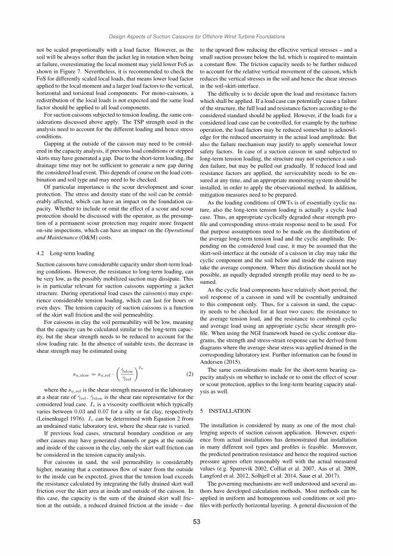
Figure 9: Some possible failure during installation, which cannot be predicted or insufficiently predicted with the available installation analysis models.
tests and/or small scale model tests, that penetration in the under-laying sand layer may not be possible without triggering a plug-liftfailure (e.g. Cotter 2009). They recommend to stop the penetrationabove the sand layer, where the maximum allowable penetrationdepth into the clay is given by the shear strength of that layer be-low the skirt tip and the caisson geometry. However, installationsof suction caissons in such layered soil profiles have demonstrated,that a penetration is in principal possible without a measurable soilplug-lift. In installations, where pore pressure sensors were placedat the in- and outside of the skirt walls above tip, it was found thatthe pressure gradient in the sand layer around the skirt tip, equatesthe gradient measured in installations in homogeneous clean sanddeposits. That supports the assumption that a plug lift failure is not
necessary. However, to generate a gradient in the sand layer cov-ered by the clay, a seepage flow must have been developed. As thewater cannot flow out through the soil plug in the caisson, the sandlayer below the clay layer needs to take the water volume, meaningthat the sand will reduce its density. Thus despite the fact, that thetrial installations demonstrated that a penetration in layered soilsis possible, it is recommended to penetrate relatively fast to avoidexcessive loosening (soil plug heave) or eventually a soil plug lift.
5.2 Challenges
The methods mentioned in Subsection 5.1 are applicable for ide-alized conditions, i.e. uniform and homogeneous soil conditions
55
Proceedings of TC 209 Workshop - 19th ICSMGE, Seoul 20 September 2017Foundation design of offshore wind structures
or perfectly horizontal layering, vertical and parallel skirts, and nostructural imperfections, to name but a few. However, there area number of situations which are not covered. Some of the mostcommon ones are illustrated in Figure 9.
Soil plug lift is a failure often discussed in connection with pen-etration in layered soils. In contrast to soil plug heave, soil plug liftwill generate a water filled void or gap in the ground. That needsto be avoided in order to not negatively affect the in-place behaviorof the suction caisson. Furthermore soil plug lift may prevent thecaisson from penetrating to the TPD as the caisson will be filledup with soil. Practical experience form installations in layered soilprofiles suggest to apply a minimum penetration rate in order toreduce the amount of water flowing into the soil plug and potentialvoid.
Piping is a critical failure, as the volume of water per time flow-ing from the outside to the inside will increase considerably. If thewater volume exceeds a certain amount, the pump may not be ableto apply the required suction pressure and the TPD may not bereached. Furthermore, piping channels generated during installa-tion can negatively affect the in-place performance, as the tempo-rary suction during short-term loading will dissipate much fasterwhich can potentially decreases the capacity significantly. Pipingcan be triggered by obstacles below the skirt tip which are draggeddown while penetrating the caisson. These obstacles can leave ahighly disturbed zone along the skirt wall. But also locally vary-ing soil properties in combination with penetration at high suctionpressures and hence penetration rate can trigger the generation ofpiping.
Excessive loosening may occur in installation in permeablesoils. Due to the reduced vertical stresses and additional shear-ing of the material inside the caisson, the soil will dilate. Thatwill affect the soil permeability and hence the seepage flow pat-tern, which can prevent the caisson to reach the TPD, since therequired flow gradient in the soil cannot be achieved. Experiencefrom installations in homogeneous sand deposits indicate that thedegree of loosening correlates positively with the installation time,meaning that penetration at higher rate may potentially avoid ex-cessive loosening. Sturm et al. (2015) proposes safety factors forthe penetration analysis capturing the uncertainty of an excessiveloosening.
Embedded and thin granular but relatively low permeable soillayers and lenses may cause the caisson to stuck, if the requiredsuction pressure exceeds an allowable value and if no seepage flowcan be mobilized in that layer, which would reduce the tip resis-tance considerably.
An uneven mudline may prevent the caisson to reach the TPD,if not considered in the design of the so-called free height, whichis the skirt length in addition to the calculated required penetra-tion depth. The free height is typically measured from the originalmudline and need to accommodate the soil plug heave, grout, andpre-installed filter material if applied, and seabed elevation. Anuneven mudline can be also critical for the self-weight penetrationphase, if the penetration resistance is locally too high preventingthe whole caisson circumferences to penetrate and to establish asealing, which is required to apply a suction pressure.
Soil layers with a gap graded grain size distribution curve,where the large diameter grains can form a stable matrix, are sensi-tive to inner erosion. Fine grained particles are washed out of thesoil due to the applied suction, and a very high permeable grainskeleton remains in the ground. Since the amount of water volumeflowing into the caisson per time increases, the pump may not beable to apply the required suction pressure, meaning that the TPDcannot be reached.
Tilt of the caisson can be critical, as the penetration resistance
increases. Installations with single caissons and anchors showedthat a caisson is a self-stabilizing system, meaning that it recti-fies due to the lateral soil resistance. However, if the caisson isconstrained – for example when attached to a jacket – the loadscan become critical for the sub-structure. Thus it is important toensure a minimum degree of verticality of all caisson of a multi-legged sub-structure during the fabrication.
Boulders and other large obstacles can prevent the caisson toreach the TPD as the penetration resistance will increase consider-ably. If not identified in due time by the pump operator, the cais-son skirts may be damaged or buckled. Small boulders may flipor pushed to the inside due to the suction pressure. Boulders canbe detected by means of suitable geophysical site investigations. Ifboulders are met, the caisson may be retrieved and relocated, giventhat the structure has not been damaged.
If the submerged weight of the caisson and substructure is toolow, the self-weight penetration may not be sufficient to ensure aseal at skirt tip level, which is necessary to apply a suction pressure.
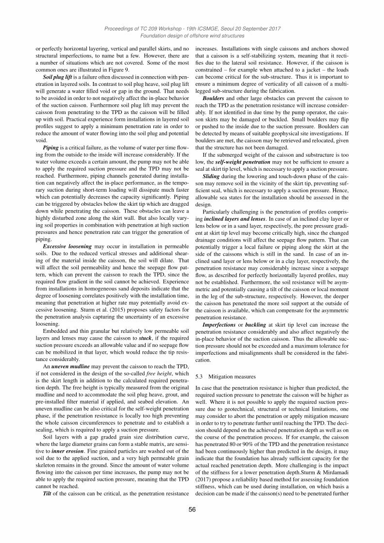
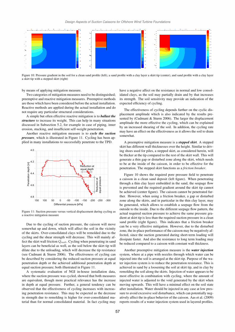
Sliding during the lowering and touch-down phase of the cais-son may remove soil in the vicinity of the skirt tip, preventing suf-ficient seal, which is necessary to apply a suction pressure. Hence,allowable sea states for the installation should be assessed in thedesign.
Particularly challenging is the penetration of profiles compris-ing inclined layers and lenses. In case of an inclined clay layer orlens below or in a sand layer, respectively, the pore pressure gradi-ent at skirt tip level may become critically high, since the changeddrainage conditions will affect the seepage flow pattern. That canpotentially trigger a local failure or piping along the skirt at theside of the caissons which is still in the sand. In case of an in-clined sand layer or lens below or in a clay layer, respectively, thepenetration resistance may considerably increase since a seepageflow, as described for perfectly horizontally layered profiles, maynot be established. Furthermore, the soil resistance will be asym-metric and potentially causing a tilt of the caisson or local momentin the leg of the sub-structure, respectively. However, the deeperthe caisson has penetrated the more soil support at the outside ofthe caisson is available, which can compensate for the asymmetricpenetration resistance.
Imperfections or buckling at skirt tip level can increase thepenetration resistance considerably and also affect negatively thein-place behavior of the suction caisson. Thus the allowable suc-tion pressure should not be exceeded and a maximum tolerance forimperfections and misalignments shall be considered in the fabri-cation.
5.3 Mitigation measures
In case that the penetration resistance is higher than predicted, therequired suction pressure to penetrate the caisson will be higher aswell. Where it is not possible to apply the required suction pres-sure due to geotechnical, structural or technical limitations, onemay consider to abort the penetration or apply mitigation measurein order to try to penetrate further until reaching the TPD. The deci-sion should depend on the achieved penetration depth as well as onthe course of the penetration process. If for example, the caissonhas penetrated 80 or 90% of the TPD and the penetration resistancehad been continuously higher than predicted in the design, it mayindicate that the foundation has already sufficient capacity for theactual reached penetration depth. More challenging is the impactof the stiffness for a lower penetration depth.Sturm & Mirdamadi(2017) propose a reliability based method for assessing foundationstiffness, which can be used during installation, on which basis adecision can be made if the caisson(s) need to be penetrated further
56
Design Aspects of Suction Caissons for Offshore Wind Turbine Foundations
Figure 10: Pressure gradient in the soil for a clean sand profile (left), a sand profile with a clay layer a skirt tip (center), and sand profile with a clay layera skirt tip with a stepped skirt (right)
by means of applying mitigation measure.Two categories of mitigation measures need to be distinguished;
preemptive and reactive mitigation measures. Preemptive methodsare those which have been considered before the actual installation.Reactive methods are applied during the actual installation and donot require any particular structural considerations.
A simple but often effective reactive mitigation is to ballast thestructure to increase its weight. This can help in many situationsdiscussed in Subsection 5.2, for example in case of piping, innererosion, stucking, and insufficient self-weight penetration.
Another reactive mitigation measure is to cycle the suctionpressure, which is illustrated in Figure 11. Cycling has been ap-plied in many installations to successfully penetrate to the TPD.
Figure 11: Suction pressure versus vertical displacement during cycling asa reactive mitigation measure
Due to the cycling of suction pressure, the caisson will movesomewhat up and down, which will affect the soil in the vicinityof the skirts. Over-consolidated clays will be remolded due to thecycling and the shear strength will decrease. This will mainly af-fect the skirt wall frictionQwall. Cycling when penetrating in sandlayers can be beneficial as well, as the soil below the skirt tip willdilate due to the unloading, which will decrease the tip resistance(see Cudmani & Sturm 2006). The effectiveness of cycling canbe described by considering the reduced suction pressure at equalpenetration depth or the achieved additional penetration depth atequal suction pressure; both illustrated in Figure 11.
A systematic evaluation of NGI in-house installation data,where the suction pressure was cycled, showed that both measuresare equivalent, though more practical relevance has the increasein depth at equal pressure. Further, a general tendency can beobserved that the effectiveness of cycling increases with increas-ing penetration resistance. This may be expected as the decreasein strength due to remolding is higher for over-consolidated ma-terial than for normal consolidated material. In fact cycling may
have a negative affect on the resistance in normal and low consol-idated clays, as the soil may partially drain and by that increasesits strength. The soil sensitivity may provide an indication of theexpected efficiency of cycling.
The effectiveness of cycling depends further on the cyclic dis-placement amplitude which is also indicated by the results pre-sented by (Cudmani & Sturm 2006). The larger the displacementamplitude the more effective the cycling, which can be explainedby an increased shearing of the soil. In addition, the cycling ratemay have an effect on the effectiveness as it allows the soil to drainsomewhat.
A preemptive mitigation measure is a stepped skirt. A steppedskirt has different wall thicknesses over the height. Similar to driv-ing shoes used for piles, a stepped skirt, as considered herein, willbe thicker at the tip compared to the rest of the skirt wall. This willgenerate a thin gap or disturbed zone along the skirt, which needsto be at the inside of the caisson, in order to be effective for thepenetration. The stepped skirt functions as a friction breaker.
Figure 10 shows the required pore pressure field to penetratea caisson in a clean sand deposit (left figure). When penetratingthrough a thin clay layer embedded in the sand, the seepage flowis prevented and the required gradient around the skirt tip cannotbe achieved (center figure). The caisson cannot be penetrated fur-ther. However, when using a friction breaker, a gap or disturbedzone along the skirts, and in particular in the thin clay layer, maybe generated, which allows to establish a seepage flow from theoutside to the inside. Due to the different seepage flow pattern, theactual required suction pressure to achieve the same pressure gra-dient at skirt tip is less than the required suction pressure in a cleansand profile (right figure). This indicates that a friction breakercan be a very effective mitigation. However, due to the disturbedzone, the in-place performance of the caisson may be negatively af-fected, since the suction generated during short-term loading willdissipate faster. And also the resistance to long term loading maybe reduced compared to a caisson with constant wall thickness.
Another preemptive mitigation measure is the water injectionsystem, where at a pipe with nozzles through which water can beinjected into the soil is arranged at the skirt tip. Purpose of the wa-ter injection system is to reduce the penetration resistance. This isachieved in sand by a loosening the soil at skirt tip, and in clay byremolding the soil along the skirts. Injection of water appears to bemost effective in combination with cycling, where the amount ofinjected water is adjusted to the void generated by the skirt whenmoving upwards. This will have a minimal effect on the soil stateafter installation. Water should be injected in any case at low pres-sure to avoid excessive soil disturbance, which can potentially neg-atively affect the in-place behavior of the caisson. Aas et al. (2009)reports results of a water injection system used in layered profiles.
57
Proceedings of TC 209 Workshop - 19th ICSMGE, Seoul 20 September 2017Foundation design of offshore wind structures
6 FOUNDATION SERVICEABILITY
The foundation serviceability is probably one of the most impre-cisely predictable aspects in geotechnical engineering. Service-ability in this context means settlements, lateral displacements, androtation or tilt, respectively. Most critical is the tilt of an OWT as itaffects the operation of the turbine. Pure settlements are typicallyless critical, though some secondary steel components such as theJ-tube or the boat lander may be affected. The lateral displace-ments are typically small, and have practically no relevance in theprojects considered so far. Thus main focus is given in the follow-ing on differential settlements or tilt of multi-legged substructuresor mono-caissons, respectively.
In order to assess the Serviceability Limit State (SLS), corre-sponding limit values need to be defined. These are typically givenby the turbine supplier. In addition, the maximum tilt may be lim-ited in order to reduce operational loads, which is in particular rel-evant for multi-legged OWTs; increased average tilt yield typicallyan increased average tension load.
Three different types of settlement/tilt components need to bedistinguished:
• Static settlement/tilt due to the submerged weight of theOWT.
• Peak settlement/tilt due to a ULS loads.
• Accumulated (average) settlement/tilt due to cyclic loadingfrom wind, wave and operation loads.
Following traditional geomechanics, the static settlement/tiltcan be further distinguished into immediate-, consolidation- andcreep-settlements/tilt. The corresponding values can be computedusing well established geotechnical calculations procedures.
The peak settlement/tilt can be assessed by means of a mono-tonic pushover FE analysis. The soil model needs to be cali-brated in order to reproduce the correct stress-strain-behavior ofthe soil. Where necessary, the decrease of strength and stiffnessdue to cyclic loading needs to be included. This may be done forexample by using a total-stress-based model with adjusted stress-strain curves based on cyclic contour diagrams, or an effective-stress-based model to which a pore pressure field is superimposed;see also Section 3. The peak settlement/tilt represents actually themaximum expected value, meaning that the load case consideredis in general the same used in the ULS capacity analysis, but with-out applying load and resistance factors. Practically, this value isless relevant, as the settlement – and more important the tilt – willimmediately decrease again in the subsequent unloading. Further,the OWT may not be in operation during the ULS event, for whichreason the allowable serviceability limit criteria may not apply.
Most relevant is the assessment of the accumulated average set-tlement/tilt, which, however, is also one of the most challengingcomponents. Thereto, different strategies can be applied. One ofthe most conservative assumptions is to take all load cycles whichoccur during the lifetime of an OWT and sort them in ascendingorder. This sorted cyclic load history can be applied in a calcula-tion procedure, for example in the NGI method (Jostad et al. 2014,2015b), or in an FE analysis using the high-cyclic accumulationmodel (Niemunis et al. 2005, Wichtmann et al. 2010).
Since small load cycles will typically not contribute signifi-cantly to the accumulated total displacements, a different approachhas been followed in more recent projects. The design storm usedin the ULS analysis, which is based on a 50 years wind wave event,has been extrapolated to other storm events with different recur-rences using a Gumble distribution. That enables to calculate the
displacements for a given cyclic history, but at different scalingfactors. The accumulated total displacements can be than deter-mined by summing up the the calculated displacements for the dif-ferent storm events multiplied with the number of occurrences ofthe corresponding event.
However, both approaches miss out important aspects. Differ-ent to engineering materials such as steel or concrete, soils are sen-sitive to the order of cyclic loading. While large cyclic load ampli-tudes can cause a degradation of the soil strength and stiffness, canthe soil regain strength and stiffness when subjected to lower cyclicload amplitudes, which can be described as self-healing. The influ-ence of varying strength and stiffness of the soil on the settlementand tilt depending on the cyclic loading conditions is described inSturm (2009) and Sturm (2011) at the example of skirted shallowfoundations. It is introduced the concept of the so-called cyclicattractor, which is a value being asymptotically approached by agiven cyclic load history with constant amplitude. Given that thefoundation is stable for all relevant cyclic load histories, the valueof the cyclic attractor is proportionally to the composition and in-tensity of the cyclic load history. Thus, for the assessment of thecyclic accumulated average tilt of a stable OWT, only the cyclicattractor for the largest cyclic load event needs to be determined,meaning that only one cyclic load history needs to be consideredin the design. Cyclic attractors can be found for the accumulatedaverage tilt of shallow foundations. However, no attractors existfor vertical settlements of shallow foundations.
7 FOUNDATION STIFFNESS
The local foundation stiffness is the link between the geotechnicaland structural designer. Foundation stiffness is an output of thegeotechnical analysis, but is not part of the actual sizing, i.e. ca-pacity serviceability and installation analysis. However, the resultsof the stiffness analysis will affect the design basis as illustrated inFigure 2. As detailed in Subsection 1.2, foundation stiffness canbe provided as single secant stiffness values, nonlinear tangentialstiffness values, or full linear or non-linear stiffness matrices in-cluding coupling terms if necessary. This needs to be agreed inupfront with the involved disciplines and may be included in theload document. Further, it need to be agreed on the load cases forwhich the foundation stiffness shall be assessed.
Foundation stiffness can be established using simplified analyt-ical methods or advanced FEM based methods. Gazetas (1991) hasproposed a large number of closed form equations for assessing thestiffness of different foundation types and ground conditions. Incontrast to the simplified methods, which consider linear soil prop-erties, the FEM allows to capture the non-linearity of the soil andthe flexibility of the structure, i.e. the soil-structure-interaction.The methods used for assessing the foundation stiffness should beadjusted based on the stage of a project and anticipated degree ofoptimization. In an early stage of a project, i.e. feasibility and con-cept study, simplified analytical methods may be used, whereas ina FEED and Detailed Design the FEM may be more appropriate.
Typically the foundation stiffness is provided as a range withhigh-, best- and low-estimate. The width of the range should benarrowed down during the project and every design iteration. Noattempts should be made by the geotechnical designer to assumeany particular soil profile which may be conservative for the struc-tural design. The selected soil profiles should rather reflect theinherent uncertainties of the soil state after installation and loadconditions.
Two different type of stiffness values need to be distinguished;stiffness values for the structural utilization (denoted in the follow-ing ULS load case) and stiffness values for the load assessment,
58
Design Aspects of Suction Caissons for Offshore Wind Turbine Foundations
0 100 200 300Norm. fatigue life t/tBE [%]
tLEtHE
50 100 150 200Norm. ULS utilization η/ηBE [%]
1
2
3
4
5
6
7
8 9
1
2
3
4
5
6
7
8
9
Sketch of jacket
1
2
3
4
5
6
7
8
9ηLEηHE
Figure 12: Impact of the HE and LE ULS and FLS stiffness on the jacket response
Figure 13: Example of a global model used for assessing local foundation stiffness
structural fatigue analysis and eigenmode analysis (denoted in thefollowing FLS load case). In general the ULS stiffness is non-linear due to the high mobilization of the foundation, wheres theFLS stiffness appears often to be linear due to the significant lowerload amplitudes. The soil profiles used in both the simplified andthe advanced analysis need to reflect the different loading condi-tions. The FLS load case is governed by the cyclic amplitude,where the average or mean load is of less important.
Table 2: Variation of the HE and LE ULS and FLS stiffness nor-malized by the corresponding Best Estimate (BE) stiffness
ULS FLS
High Estimate (HE) 288% 189%
Low Estimate (LE) 37 % 69%
Figure 12 shows the impact of the high-, best- and low-estimatefoundation stiffness on both the fatigue life and the structural uti-lization of a jacket supported by three suction caissons. Basis forthis analysis are the structural and geotechnical properties at the
end of the first iteration of a generic FEED study. The correspond-ing values are normalised by the best-estimate values. The corre-sponding normalized stiffness values are listed in Table 2.
It becomes apparent that the structural utilization scales approx-imately proportional with the ULS foundation stiffness. The vari-ation in utilization, however, is not reflecting the relatively largerange in ULS foundation stiffness values, meaning that the jacketis less sensitive to variations in foundation stiffness. In contrast tothat, is the impact of the high- and low-estimate FLS stiffness onthe fatigue life very pronounced. Even though, the low estimateFLS stiffness is 69% of the best-estimate FLS stiffness, the fatiguelife decreases to less than 10%.
This example illustrates, that an optimization of an OWT can bechallenging, if the range of foundation stiffness values is too large.Furthermore the implications of assumptions in the geotechnicaldesign on the structural design can be hardly estimated withoutperforming corresponding structural analysis.
When assessing the foundation stiffness for a mono-caisson us-ing the FEM, the loads provided in the design basis can be di-rectly applied to the caisson. When using the calculated foundationstiffness values in the subsequent structural analysis the updated
59
Proceedings of TC 209 Workshop - 19th ICSMGE, Seoul 20 September 2017Foundation design of offshore wind structures
loads are typically of similar order and ratio. That means the load-stiffness iteration – outer loop in Figure 1 – converge relativelyfast.
This is somewhat more complicated for multi-legged sub-structures. Depending on the footprint width, caisson dimensions,load conditions, and ground conditions, the loads can be redis-tributed between the different legs due to both the flexibility ofthe sub-structure – i.e. the jacket – and the interaction of the cais-sons in the ground. Using FE models of single caissons only willnot capture the redistribution correctly. More accurate would beto model both the caissons, the sub-structure and the soil. This isdenoted global FE model and is shown in Figure 13. The differ-ence between a global model and an integrated model is the type ofanalysis. A global model is typically used in monotonic push-overanalysis, whereas an integrated model is used in a time domainanalysis.
Advantage of a global model is, that the loads and foundationstiffness values can converge relatively fast in just some few load-stiffness iterations. However, such analysis are time consuming,and – depending on the stage of a project – single caisson modelsmay be used instead, though the accuracy is less good. Based onrecent experience, it is recommended to use global FE model inFEED and detailed design at some representative locations of anoffshore wind farm. The identification of relevant locations canbe reasonably well done using the simplified methods or single FEmodels, as the error is in general proportional.
It may be noted that global FE models are particular relevantfor assessing ULS foundation stiffness due to the large mobiliza-tion. For FLS load cases, single caissons models are sufficient. Anexception is the assessment of foundation damping, both for ULSand FLS. If FE analysis is used for determine foundation damping,the complete soil may be modeled to capture the interaction andlarger soil mass.
In addition should be mentioned that attempts are undertaken touse macro elements in structural analysis. However, the macro ele-ments require a calibration of the particular site and caisson geom-etry, which can be done for some models using the above describedmethods.
8 SOIL REACTIONS
Soil reactions are, like foundation stiffness, an output of thegeotechnical design, but are not considered in the geotechnical siz-ing of the caisson. However, the results of the stiffness analysiscan affect the design basis as illustrated in Figure 2. Soil reactionsare typically provided as loads distributed over the skirt(s) and lidwhich is in contact with the soil. The assessment of load reactionsis difficult and depends on many factors, such as the flexibility ofthe caisson, the soil layering, the recent cyclic load history, and theactual applied load for which the soil reactions shall be provided.
Soil reactions are used for the structural design of the caisson,and need to be provided for two different cases; for installation andfor in-place conditions. The soil reactions during installation willtypically govern the required thickness and shape of the skirt wall –assessed in buckling analysis – whereas the in-place soil reactionswill primarily govern the design of the caisson lid. Of particularimportance is the distribution of the loads carried by the lid and theskirts.
Figures 14 and 15 show the result of FE analysis of five suctioncaissons with different geometries and soil conditions, subjectedto short-term compression or tension loading, respectively. Theload conditions are representative for a compression or tension legof a multi-legged sub-structure. From Figure 14 becomes appar-ent, that the load taken by the lid scales proportionally with the
0
10
20
30
40
50
60
70
-40 -20 0 20 40 60 80 100
Inte
gra
ted
lid
pre
ssu
re /
ve
rtic
al lo
ad
[
%]
Vertical load / ULS compression load [%]
L01L02L03L04L05
Figure 14: Ration between the loads carried by the lid and the skirts asfunction of the load amplitude
-40
-20
0
20
40
60
80
100
-0.01 0 0.01 0.02 0.03 0.04 0.05 0.06 0.07
Ve
rtic
al lo
ad
/ U
LS
co
mp
ressio
n lo
ad
[
%]
Lid deflection [mm]
L01L02L03L04L05
Figure 15: Deflection of the lid as function of the load amplitude
applied load. Small load amplitudes are taken solely by the skirts.The increase in lid pressure is linear and larger for tension loading,though a considerable scatter can be observed on the tension side.
Figure 15 shows the displacements of the caisson at the load-ing point, which is in this case the top of the lid. It appears to bevery linear for low and medium sized load amplitudes, whereasit becomes pronounced non-linear for larger loads. Variationsof the lid and caisson stiffness showed, that the linear responseat low and medium sized loads is directly proportionally to thecaisson stiffness. The soil non-linearity becomes first visible atlarger loads. This demonstrates the importance to select the correctgeotechnical-structural interface point discussed in Section 1.2.
Thought the results are encouraging, the calculation of the ac-tual values using the FEM is very time consuming and sensitiveto the modeling. The stresses depend on the size, number, shape,and type of continuum element used in the analysis. Further, thetip resistance is difficult to assess due to the ratio of wall thicknessto caisson diameter, which requires exceptionally small elementsalong the skirt and below the tip. Thus, the FEM may be used as acomplementary method for assessing the soil reactions.
In conventional offshore geotechnical engineering, soil reac-tions are established based on engineering judgement and are pro-vided as so-called unit loads. Unit loads scale proportionally withthe applied total load. Assumptions are made on the distribution;similar to the one shown in Figure 14. Upper and lower estimatesof the distribution need to be provided.
Soil reactions for the installation can be derived from the ac-
60
Design Aspects of Suction Caissons for Offshore Wind Turbine Foundations
tual penetration analysis, where both skirt wall friction, skirt tipresistance, and required suction pressure are calculated. Morecomplicated is to assess the soil support during installation. Itmay be assumed that almost no support is provided for penetra-tion in sand where significant flow gradients in the soil plug isexpected (drained penetration). Some support may be assumed forundrained penetration, which may be estimated based on suitablelaboratory tests.
9 OTHER ASPECTS
9.1 Grouting
An issue often discussed is the necessity of grouting. Grout is usedto fill the void between the lid and the soil at the inside of thecaisson. Most suction caissons and anchors installed so far weregrouted with only some few exception. Main reason of using groutfor suction caissons of bottom fixed OWTs is to reduce or avoidpotential (differential) settlements, and pumping-effects. Due tocyclic vertical loading, the water cushion below the lid is exposedto continuous pressure pulses, which can trigger a local piping fail-ure along the skirts. In addition, a lack of soil/grout support belowthe lid will cause large local stresses and moments in the lid. Allloads need to be transferred trough the lid into the skirts. This re-quires a thick, massive lid, to avoid large deflections and fatigueissues.
In order to improve the bearing behavior of the lid and andto avoid the afore mentioned negative effects when omittinggrout, structural components may be applied to replace the grout.Stopper-pods, which are elements made of steel, hard rubber, orcomposite materials, can be attached under the lid. The caissonneed to penetrate until the pods are in contact with the mudlineenabling to transfer loads from the lid into the soil. Alternatively,small ribs or T-beams may be welded under the lid dividing thebase into compartments. The structural elements may be slightlycone-shaped to allow partially penetration into the ground in orderto compensate for inclined mudline or uneven soil heave. If, anuneven soil surface is expected, a jetting system may be used toflush the upper soil and by that generating a slurry mixture whichslowly consolidated during the final phase of the installation.
Disadvantage with using structural and jetting systems is, thatthe soil which is in contact with the structural components is soft,and the stresses in the lid may be concentrated to some few pointsonly. Based on current experience, the use of grout seems to beappropriate to optimize the lid geometry. However, the cost sav-ings due to an optimized lid geometry, needs to be compared to thecosts of the additional offshore work for the grouting.
9.2 Integrated design approach
As mentioned in the several sections, so-called integrated analysisare performed in OWT design (e.g. Krathe & Kaynia 2016, Pageet al. 2016, Skau et al. 2017). Such analysis are particularity suitedfor structural analysis, such as in the load or eigenmode assess-ment. Integrated analysis are not appropriate for the foundationsizing, though some macro-elements may indicate this possibil-ity. The foundation response can be very sensitive to soil layeringand size of the caisson and skirt, which cannot be considered bythe macro-elements. Furthermore, also other aspects than capacityand serviceability may be design driving as detailed in the corre-sponding sections in this contribution.
Until today, the geotechnical sizing is uncoupled from the struc-tural analysis and it is not expected that this may change in the nearfuture without compromising an optimization of the caisson geom-etry.
9.3 Earthquake loading
In some parts of the world, earthquake loading and earthquake in-duced liquefaction needs to be considered in the design. Both canbe considered in the design using existing methods. The loads fromthe earthquake represent just another load case to which particularsoil conditions need to be assigned in the corresponding analysis.Kaynia (2017) provides a comprehensive introduction to the de-sign of OWTs subjected to earthquake loading.
9.4 Observational method
OWTs supported by caissons are a relatively new concept andlong-term experience does not exist yet. Thus, the observationalmethod may be considered in current projects. It can be appliedduring both installation and operation. In order to use the obser-vational method, it is important that the failure is ductile, whichallows to initiate mitigation measures(s) in time.
The observational method is a combination of predictions andmeasurements. The behavior of the OWT is calculated using ex-isting methods. Further, ranges of allowable values need to be de-fined. If exceeded, mitigation measures need to be initiated, whichneed to be planned in the forehand.
Examples of mitigation measures during installation are pre-sented in Subsection 5.3. The decision value is typically the re-quired suction pressure, which shall be provided as a range withhigh and low estimate. If the high estimate value is exceeded, themitigation measures may need to be applied. The same conceptcan be applied for the serviceability. When a maximum tilt is ex-ceeded the OWT may need to be rectified.
For a successful application, it is important to plan both an ap-propriate health monitoring system and mitigation measures. As-pects of monitoring systems are presented by Sparrevik & Strout(2015). The usefulness of such systems is presented by Schonberget al. (2017) at the example of the Borkum Riffgrund 1 SuctionBucket Jacket.
9.5 Wind farm design
So far, only single OWT foundations were considered herein. Aniterative approach as outlined in Section 1.1 at each turbine loca-tion of an Offshore Wind Farm (OWF) would require considerabletime, which may not be possible in the given project time frame.Thus, a clustering may be introduced. Typically, the clusteringis a based on the water depth, since the loads are expected to bevery similar for a given depth. Foundation capacity and installa-tion analysis can be relatively quickly performed. The results ofthese can be used for the sizing. If FEM is used for the capacityanalysis, as described by Jostad & Andersen (2015), the foundationstiffness can be qualitatively estimated. Based on that, the softestand stiffest location within a cluster can be identified. These twocan then used in the stiffness and soil reaction analysis, represent-ing the parameters used in the iteration process, given that the samesub-structure will be applied in the cluster.
10 OUTLOOK
In this article a general overview of the geotechnical design of suc-tion caissons for OWTs has been provided. The different phasesof the design were detailed, and the relevant aspects were outlined.The general design of suction caissons is reasonably well under-stood and many authors have proposed numerous methodologiesfor specific geotechnical calculations, such as capacity, installa-tion and stiffness analysis. Only some few were mentioned in thisarticle; mainly those which are familiar to the author from personal
61
Proceedings of TC 209 Workshop - 19th ICSMGE, Seoul 20 September 2017Foundation design of offshore wind structures
experience. The reader is encouraged to get himself an overviewof the numerous methods proposed in the literature. The articleat hand may serve as a guideline to evaluate the suitability of amethod for the particular design aspect.
Due to the increased interest in suction caissons for OWTs,a number of researchers and practitioners are currently workingto continuously advance the knowledge. Several of the currentlydesigned and installed OWTs are equipped with comprehensivehealth monitoring systems, which will provide further inside intothe short- and long-term behavior of suction caissons.
ACKNOWLEDGMENT
The authors gratefully acknowledge the support by his colleaguesat NGI in the numerous projects which provided the basis for thisarticle. Thanks goes to Knut H. Andersen and Youhu Zhang forthe review of the manuscript.
11 REFERENCES
Aas, P., Saue, M. & Aarsnes, J. (2009), Design predictions andmeasurements during installation of suction anchors with andwithout water-flow system to help installation through layeredsoil profiles, in ‘Offshore Technology Conference, 40. Hous-ton’, number OTC-20294-MS.
Andersen, K. (2015), Cyclic soil parameters for off-shore foundation design : The third issmge mcclel-land lecture, in V. Meyer, ed., ‘Frontiers in OffshoreGeotechnics III, Oslo, Norway’, pp. 5–82. Revisedversion in: http://www.issmge.org/committees/technical-committees/applications/offshore and click on AdditionalInformation.
Andersen, K., Jostad, H. & Dyvik, R. (2008), ‘Penetration resis-tance of offshore skirted foundations and anchors in dense sand’,Journal of geotechnological and geoenvironmental engineering134(1), 106–116.
Andersen, K., Puech, A. & Jardine, R. (2013), Cyclic resistantgeotechnical design and parameter selection for offshore engi-neering and other applications, in ‘ISSMGE - TC 209 Workshop- Design for cyclic loading: Piles and other foundations - Pro-ceedings of TC 209 Workshop, 18th ICMGE, Paris’.
BSH (2015), Minimum requirements concerning the constructivedesign of offshore structures within the Exclusive EconomicZone (EEZ), number 7005, 2 edn, BSH.
Byrne, B. (2000), Investigations of suction caissons in dense sand,PhD thesis, Department of Engineering Science, The Universityof Oxford.
Colliat, J., Dendani, H. & Schroeder, K. (2007), Installation ofsuction piles at deepwater sites in angola, in ‘Offshore Site In-vestigation and Geotechnics: Confronting New Challenges andSharing Knowledge (SUT-OSIG)’.
Cotter, O. (2009), The installation of suction caisson foundationsfor offshore renewable energy systems, PhD thesis, Universityof Oxford, Magdalen College.
Cotterill, C., Phillips, E., James, L., Forsberg, C., Tjelta, T., Carter,G. & Dove, D. (2017), ‘The evolution of the dogger bank, northsea: A complex history of terrestrial, glacial and marine environ-mental change’, Quaternary Science Reviews (171), 136–153.
Cudmani, R. & Sturm, H. (2006), An investigation of the tip re-sistance in granular and soft soils during static, alternating anddynamic penetration, in ‘Int. Sym. on vibratory pile driving anddeep soil compaction, TRANSVIB’.
DNV-GL (2016), Support structures for wind turbines, StandardDNVGL-ST-0126.
Dove, D., Roberts, D., Evans, D., Tappin, D., Lee, J., Long, D.,Mellett, C. & Callard, S. (2016), Refining glacial statigraphyin the southern north sea - new bathymetric model brings re-newed value to legacy seismic, in ‘Near Surface Geoscience2016 - Second Applied Shallow Marine Geophysics Confer-ence’, EAGE.
Foglia, A., Govoni, L., Gottardi, G. & Ibsen, L. (2014), Investi-gations on macro-element modelling of bucket foundations foroffshore wind turbines, DCE Technical Memorandum 48, Aal-borg: Department of Civil Engineering, Aalborg University.
Forsberg, C., Lunne, T., Vanneste, M., James, L., Tjelta, T., Bar-wise, A. & Duffy, C. (2017), Synthetic cpts from intelligentground models based on the integration of geology, geotechnicsand geophysics as a tool for conceptual foundation design andsoil investigation planning, in ‘Offshore Site Investigation andGeotechnics: Smarter Solutions for Future Offshore Develop-ments (SUT-OSIG)’.
Gazetas, G. (1991), Foundation vibrations, in H.-Y. Fang,ed., ‘Foundation Engineering Handbook’, Springer Sci-ence+Business Media.
Houlsby, G. & Byrne, B. (2005a), ‘Design procedures for instal-lation of suction caissons in clay and other materials’, Proceed-ings of the Institution of Civil Engineers - Geotechnical Engi-neering 158(GE2), 75–82.
Houlsby, G. & Byrne, B. (2005b), ‘Design procedures for installa-tion of suction caissons in sand’, Proceedings of the Institutionof Civil Engineers - Geotechnical Engineering 158(GE3), 135–144.
IEC (2009), Wind turbines - part 3: Design requirements for off-shore wind turbines, Standard IEC 61400-3:2009, InternationalElectrotechnical Commission.
Johansson, P., Aas, P. & Hansen, S. (2003), Field model tests fora novel suction anchor application, in ‘6. International Sympo-sium on Field Measurements in Geomechanics, Oslo, Norway’,pp. 145–153.
Jostad, H. & Andersen, K. (2015), Calculation of undrained hold-ing capacity of suction anchors in clays, in V. Meyer, ed., ‘Fron-tiers in Offshore Geotechnics III, Oslo, Norway’, pp. 263–268.
Jostad, H., Andersen, K., Khoa, H. & Colliat, J. (2015a), Interpre-tation of centrifuge tests of suction anchors in reconstituted softclay, in V. Meyer, ed., ‘Frontiers in Offshore Geotechnics III,Oslo, Norway’, pp. 269–276.
Jostad, H., Grimstad, G., Andersen, K., Saue, M., Shin, Y. & You,D. (2014), ‘A fe procedure for foundation design of offshorestructures – applied to study a potential owt monopile foun-dation in the korean western sea’, Geotechnical Engineering45(4), 63–72.
Jostad, H., Grimstad, G., Andersen, K. & Sivasithamparam, N.(2015b), A fe procedure for calculation of cyclic behaviourof offshore foundations under partly drained conditions, inV. Meyer, ed., ‘Frontiers in Offshore Geotechnics III, Oslo, Nor-way’, pp. 153–172.
Kaynia, A. (2017), Earthquake response of offshore wind turbines,in ‘International Conference on Performance-based Design inEarthquake Geotechnical Engineering (PBD-III)’.
Kelly, R., Houlsby, G. & Byrne, B. (2006), ‘A comparison of fieldand laboratory tests of caisson foundations in sand and clay’,Géotechnique 56(9), 617–626.
Krathe, V. & Kaynia, A. (2016), ‘Implementation of a non-linearfoundation model for soil-structure interaction analysis of off-shore wind turbines in fast’, Wind Energy 20(4), 695–712.
Langford, T., Solhjell, E., Hampson, K. & Hondebrink, L. (2012),Geotechnical design and installation of suction anchors for theskarv fpso, offshore norway, in ‘Offshore Site Investigation and
62
Design Aspects of Suction Caissons for Offshore Wind Turbine Foundations
Geotechnics: Integrated Geotechnologies - Present and Future(SUT-OSIG)’, pp. 613–620.
Leinenkugel, H. (1976), Deformations- und Festigkeitsverhal-ten bindiger Erdstoffe. Experimentelle Ergebnisse und ihrephysikalische Deutung, PhD thesis, University of Karlsruhe.
Nguyen-Sy, L. (2005), The theoretical modelling of circular shal-low foundations for offshore wind turbines, PhD thesis, Univer-sity of Oxford, Magdalen College.
Nguyen-Sy, L. & Houlsby, G. (2005), The theoretical modellingof a suction caisson foundation using hyperplasticity theory, in‘Frontiers in Offshore Geotechnics I, Perth, Austrlia’, pp. 417–423.
Niemunis, A., Wichtmann, T. & Triantafyllidis, T. (2005), ‘A high-cycle accumulation model for sand’, Computers and Geotech-nics 32(4), 245–263.
Norén-Cosgriff, K., Jostad, H. & Madshus, C. (2015), Idealizedload composition for determination of cyclic undrained degra-dation of soils, in V. Meyer, ed., ‘Frontiers in Offshore Geotech-nics III, Oslo, Norway’, pp. 1097–1102.
Page, A. M., Schafhirt, S., Eiksund, G., Skau, K., Jostad, H. &Sturm, H. (2016), Alternative numerical pile foundation mod-els for integrated analyses of monopile-based offshore wind tur-bines, in ‘26. International Offshore and Polar Engineering Con-ference (ISOPE)’, pp. 111–119.
Salciarini, D., Bienen, B. & Tamagnini, C. (2011), A hy-poplastic macroelement for shallow foundations subject to six-dimensional loading paths, in ‘International Symposium onComputational Geomechanics (ComGeo II), Cavtat-Dubrovnik,Croatia’, pp. 721–733.
Salciarini, D. & Tamagnini, C. (2009), ‘A hypoplastic macroele-ment model for shallow foundations under monotonic and cyclicloads’, Acta Geotechnica 4(3), 163–176.
Saue, M., Aas, P., Andersen, K. & E., S. (2017), Installation ofsuction anchors in layered soils, in ‘Offshore Site Investigationand Geotechnics: Smarter Solutions for Future Offshore Devel-opments (SUT-OSIG)’.
Schonberg, A., Harte, M., Aghakouchak, A., Brown, C., Andrade,M. & Liingaard, M. (2017), Suction bucket jackets for offshorewind turbines: applications from in situ observations, in ‘In Pro-ceedings of TC209 Workshop (Foundation design of offshorewind structures): 19th International Conference on Soil Me-chanics and Geotechnical Engineering, Seoul, South Korea’.
Senders, M. & Randolph, M. (2009), ‘Cpt-based method for theinstallation of suction caissons in sand’, Journal of geotechno-logical and geoenvironmental engineering 135(1), 14–25.
Skau, K., Chen, Y. & Jostad, H. (2017), ‘A numerical study of ca-pacity and stiffness of circular skirted foundations in clay sub-jected to combined static and cyclic general loading’, Géotech-nique .
Solhjell, E., Blaker, Ø., Knudsen, S. & Rahim, A. (2014), Geotech-nical design and installation of suction anchors for the goliatfpso, offshore norway, in ‘Offshore Technology ConferenceAsia, Kuala Lumpur, Malaysia’, number OTC-24989-MS.
Sparrevik, P. (2002), Suction pile technology and installation indeep waters, in ‘34. Offshore Technology Conference (OTC),Houston, US’, number OTC 14241.
Sparrevik, P. & Strout, J. (2015), Novel monitoring solutions solv-ing geotechnical problems and offshore installation challenges,in V. Meyer, ed., ‘Frontiers in Offshore Geotechnics III, Oslo,Norway’.
Sturm, H. (2009), ‘Numerical investigation of the stabilisation be-haviour of shallow foundations under alternate loading’, ActaGeotechnica 4(4), 283–292.
Sturm, H. (2011), ‘Geotechnical performance of a novel grav-ity base type shallow foundation for offshore wind turbines’,Geotechnik 34(2), 85–96.
Sturm, H. & Mirdamadi, A. (2017), Reliability based stiffnessanalysis for application during installation of suction cais-sons, in ‘Proceedings of the 36th International Conferenceon Ocean, Offshore and Arctic Engineering, OMAE’, numberOMAE2017-62043.
Sturm, H., Nadim, F. & Page, A. (2015), A safety concept forpenetration analyses of suction caissons in sand, in V. Meyer,ed., ‘Frontiers in Offshore Geotechnics III, Oslo, Norway’,pp. 1393–1398.
Svanø, G., Eiksund, G., Kavli, A., Langø, H., Karunakaran, D.& Tjelta, T. (1997), Soil-structure interaction of the draupner ebucket foundation during storm conditions, in ‘8. InternationalConference on the Behaviour of Offshore Structures, Delft’,Vol. 1, pp. 163–176.
Wichtmann, T., Niemunis, A. & Triantafyllidis, T. (2010), Appli-cation of a high-cycle accumulation model for the predictionof permanent deformations of the foundations of offshore windpower plants, in ‘Frontiers in Offshore Geotechnics II, Perth,Austrlia’.