38
29/10/2014 Electrification Infrastructure Whole Life Cost Reduction Congress 2014 Design Best Practices for New HS Routes Jan Hauben, Paul Tobback, Sam Breugelmans, David Van de Sype

29/10/2014
Electrification Infrastructure Whole Life Cost Reduction Congress 2014 Design Best Practices for New HS Routes Jan Hauben, Paul Tobback, Sam Breugelmans, David Van de Sype

Introduction
29/10/2014 2
CEO
I-TMS I-AM I-B
TUC RAIL
I-FBA I-HRO I-ICT I-CPA

Introduction
29/10/2014 3
200km newly built high-speed railway lines with design speed of 320 km/h electrified in 2 x 25 kV AC (50Hz). 114km modernised railway lines with design speed up to 200 km/h electrified in 3 kV DC.
314 km of high speed network
integrated in the existing railway infrastructure
(1992 – 2009)

Introduction
What is the difference between HS and CR?
Nothing?
Power and energy: - 𝐹↓𝐷 = 1/2 𝜌𝑣↑2 𝐶↓𝐷 𝐴= 𝐸↓𝐷 - 𝑃↓𝐷 = 1/2 𝜌𝑣↑3 𝐶↓𝐷 𝐴
Speed 30 m/s - ED = 1.6 kWh / km - PD = 175 kW
29/10/2014 4
Speed 90 m/s - ED = 14.6 kWh / km - PD = 4.7 MW

Introduction
What is the difference between HS and CR? Maximum operating speed < 70% of wave propagation speed
v↓c =√T↓CW /m↓CW =√σ↓CW /ρ↓CW => Interaction between contact wire and pantograph becomes important
29/10/2014 5
Material Vmax [kmph]
Cu ETP 287
Cu Ag 0.1 341
Cu Sn 0.2 373
Cu Mg 0.5 395
Cu Cr Zr 450
ACSR 586

Electrical design – supply voltage
29/10/2014 6
DC
Quasi-DC
AC

Electrical design – supply voltage
TSI ENE CR: 25 kV 50Hz = standard supply voltage
TSI ENE HS is less explicit
Why was 3 kV the limit for DC?
- Series motors of 1500 VDC
- Diode reverse breakdown voltage
- Circuit breakers
29/10/2014 7

Electrical design – supply voltage
Current state of the art for traction:
⇒ DC voltages larger than 10kV are feasible ⇒ Need for traction transformer?
29/10/2014 8
6.5 kV 750 A

Electrical design – supply voltage
State of the art for circuit breakers
29/10/2014 9
ABB: Single cell of HVDC breaker 9 kA @ 80 kV

Electrical design – supply voltage
Advantages DC - DC transmission = more efficient - No zero crossings of power - No inverse current in 3-phase network - No inductance e.g. 𝑍 =0.139+𝑗0.366 Ω/km - No skin effect in rails 𝑍↓𝐴𝐶 ≈0.2+𝑗0.2 Ω/km, 𝑅↓𝐷𝐶 ≈0.03 Ω/km
Disadvantages DC - Regenerative breaking - Electrochemical corrosion due to stray currents
29/10/2014 10

Electrical design – supply voltage
Antenna supply of 30 km at 25 kV AC
Voltage drop AC: (1590 + j 2540) V => ΔV ≈ 1700 V
29/10/2014 11
25 kV
4.17 Ω j 10.98 Ω
(250 – j 50) A

Electrical design – supply voltage
Antenna supply of 30 km at 25 kV DC
Voltage drop DC: ΔV = 940 V => double-end feed: ΔV = 470 V
10 kV-15kV DC similar performance as 25 kV AC
29/10/2014 12
250 A 25 kV
3.78 Ω

Electrical design – load flow
29/10/2014 13
Load flow inputs
- Track characteristics (slopes, curves, …)
- Train characteristics
- Timetables
- Possible locations for substations
- Circuit impedances
- Catenary geometry

Electrical design – load flow
Load flow outputs (TraXim):
29/10/2014 14

Electrical design – load flow
Usage of results:
Currents: - current ratings of transformers, busbars, OCL, etc.
Voltages: - Compared to EN 50163 and EN 50388
29/10/2014 15

Electrical design – load flow
What is the load flow based upon?
What about the human factor?
29/10/2014 16
I see a lot of diesel trains

Electrical design – train voltages
Catenary impedance is mainly inductive: 𝑍 =0.139+𝑗0.366 Ω/km
Line converter may deliver reactive power (capacitive behaviour)
29/10/2014 17

Electrical design – train voltages
29/10/2014 18
Allowable see EN 50388 Annex E
Electrical design – train voltages
29/10/2014 19
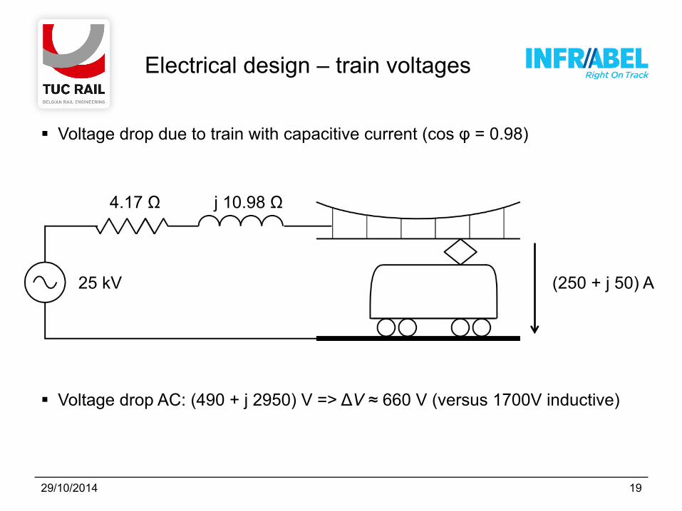
Voltage drop due to train with capacitive current (cos φ = 0.98)
Voltage drop AC: (490 + j 2950) V => ΔV ≈ 660 V (versus 1700V inductive)
25 kV
4.17 Ω j 10.98 Ω
(250 + j 50) A

Electrical design – train voltages
Future trains may be designed to deliver capacitive power
Capacitive power may be determined by measured voltage at pantograph
Voltage drop becomes less of an issue
Currents are most important
⇒ Calculate voltages with actual traffic and unfavourable cos φ?
⇒ Demand capacitive behaviour of future trains?
29/10/2014 20

Electrical design – currents
Transformers and autotransformers
- Design as ONAN for actual worst case load
- If needed conversion to ONAF in the future
- Increase of power of approx. 25%
29/10/2014 21

Electrical design – currents
29/10/2014 22
Current carrying capacity (ampacity) of OCL is determined by : - Resistance characteristics of conductors (for DC) - Geometry of conductors due to skin-and proximity effects (for 50 Hz AC)
Influence of environmental conditions (EN 50125-2:2003)
OCL 1 : Bz II 70 MW CuAg 120 CW OCL 2 : BzCd 94 MW CuAg 150 CW
Parameter BE DK Infrastructure Manager Infrabel Banedanmark
mean Tambiant 15 °C 10 °C
max Tambiant 40 °C 50 °C
Surrounding air velocity 1 m/s 0,6 m/s
Solar radiation 700 W/m² 1120 W/m²
Ampacity OCL 1 745 A 616 A Ampacity OCL 2 883 A 731 A

Electrical design – currents
29/10/2014 23
MW AW CW RF Ampacity Bz II 50 - CuAg 100 - 650 DC
CuCd 94 CuCd 104 CuAg 2 x 10⁷ - 1504 DC
CuCd 94 - CuAg 2 x 120 AMS 366 2314 DC
Bz II 70 - CuAg 120 - 770 AC 16⅔Hz
Bz II 120 - CuMg 120 - 1040 AC 50Hz
BzCd 94 - CuMg 150 - 1140 AC 50Hz

Mechanical design – components
Contact wire:
29/10/2014 24
Maximum operation speed < 70% of wave propagation speed (TSI ENE) v↓c =√T↓CW /m↓CW =√σ↓CW /ρ↓CW EN 50119:2009 EN 50149:2012
Material Vmax [kmph] Remark
Cu ETP 287
Cu Ag 0.1 341
Cu Sn 0.2 373
Cu Mg 0.5 395
Cu Cr Zr 450 non EN 50149
CSD-170 Japan
540 Ø 6.9 steel core 80% IACS
ACSR 586 non EN 50149 wear sensitive (Al-oxide)
CS-110 Japan
665 Ø 8 steel core 60% IACS

Mechanical design – components
Contact wire: Average wear CW 150:
Local wear (hard points) - +/-20 points on L1 - Measured wear: 1 mm
=> Expected EOL for CuAg after +/- 40 years
29/10/2014 25
Line Material Measured wear
Period Traffic
L1 Cu Ag 0.1 0.5 mm 18 years 50 trains/day
L2 Cu Mg 0.5 0.12 mm 7 years 23 trains/day

Mechanical design – components
Droppers: 15 defective droppers per year on L1
29/10/2014 26

Mechanical design – components
Droppers: (Jürgen Sogier, I-AM)
29/10/2014 27
10cm 2cm
Labo
2cm
10cm
EN 50119

Mechanical design – components
Droppers: Cu-ETP: failure after 70 000 to 300 000 cycles
CuMg or CuCd: no failure after 4 000 000 cycles
Thermal problems in 3 kV
- Contact resistance variation in clamps
29/10/2014 28

29/10/2014 29
Messenger wire:
Possible reasons - Bridge with metallic substructure - Contact wire wear - Renewal of droppers (pre-sag after renewal?) - 2 raised pantographs on loco?
Mechanical design – components
Uplift simulation with Kairos

Protected MW
Insulated dropper (Kevlar)
Mechanical design – components
29/10/2014 30

Mechanical design – sensitivities
Contact Force Simulation (Kairos)
- Non-Gaussian distribution, yet standard deviation σ is widely used (TSI ENE, EN 50318, EN 50367 …)
- Skew • Fm - 3σ < Fmin too restrictive • Fm + 3σ < Fmax possibly dangerous
local CW wear - Kurtosis
• Fm ± 3σ too restrictive
- EN 50119:2009 AC • Fmax < 300 N, v ≤ 200 kmph • Fmax < 350 N, v > 200 kmph
29/10/2014 31

Mechanical design – sensitivities
Contact Force Simulation results
- Standard deviation σ is no good parameter
- Criterium1: Minimum contact force => loss of contact
- Criterium2: Maximum contact force => local wear of CW
29/10/2014 32

# Pantographs Pantograph spacing
- TSI ENE HS: • 2 pantographs, • 200m spacing
- TSI ENE CR: • up to 6, • spacing minimum 35m (160kmph < v < 200kmph)
- EN 50367: • up to 5 AC (DK, NO, SE) and 6 DC (FR), • spacing minimum 35m (160kmph < v < 250kmph)
Mechanical design – sensitivities
29/10/2014 33
38 m 107.1 m 176.1 m

Mechanical design – sensitivities
# Pantographs Simulation conclusions
- # pantographs is not limiting (! Uplift)
- Important: • Uplift mode frequency (span length) • train speed (! Tunnels) • pantograph spacing sequence
29/10/2014 34
Kairos: 4 pantographs@250km/h

Mechanical design – sensitivities
Wind
R3 mixed on L162 - Resonance of leeward OCL - Wake Induced Vibration ?
DB OCL Re200
- Ice galloping - Aeroelastic instability :
lift and drag coefficient instability - Den Hartog Criterion: d𝐶↓𝐿 /d𝛼 + 𝐶↓𝐷 <0 sensitivity due to dynamically flexible
registration arms
29/10/2014 35

Mechanical design – sensitivities
R3 mixed - 2 contact wires BF-107 CuAg0.1 - Messenger wire 94mm² CuCd0.7 - Similar wire tension, mass
Identical eigenfrequencies - Similar dimensions
Similar wind forces
Experiments - CW midpoint - change in CW/MW tension
(tensioning equipment) + S2 contact wire clamp
eliminating eigenmodes CW
29/10/2014 36

Mechanical design – sensitivities
Wind R3 mixed on L162
- EM 130 measurements
Phenomenon - Aeolian vibrations (~ transmission lines) - Possible fractures in multistranded MW
29/10/2014 37

Conclusions
Don’t forget about DC Perform load flow calculations with known (reasonable) traffic and
unfavourable cosφ - Demand capacitive behaviour of future trains - Account for future conversion of ONAN to ONAF
Small modifications => impact reliability (infant mortality) Simulations of contact pantograph-OCL are important
- Uplift - Hard points - Loss of contact - Forget about σ
Reasonable demands (all designs are conservatif)
29/10/2014 38


