44
Project Final Report for ECE 658 Component Based Software Systems GROUP 11 Seongha Han (20520583) Design Collaboration with security

Project Final Report for
ECE 658 Component Based Software Systems
GROUP 11
Seongha Han (20520583)
Design Collaboration with security

1 | P a g e
Contents 0. ABSTRACT .................................................................................................................................................. 4
I. INTRODUTION ............................................................................................................................................ 4
1) Product and Collaboration .................................................................................................................... 4
2) Definition of PLM Features ................................................................................................................... 5
II. DESCRIPTION ............................................................................................................................................. 6
1) Cad Content Security ........................................................................................................................ 6
2) Collaboration with Policy .................................................................................................................. 7
III. EXSITING APPROACH ................................................................................................................................ 7
1) Security Management for CAD data ..................................................................................................... 7
3) Policy Based Collaboration Management ......................................................................................... 8
IV. BENEFIT OF THESE METHODS .................................................................................................................. 8
V. DATA/PROCESS FLOW............................................................................................................................... 9
VI. LIMITATION OF PROOF OF CONCEPT .................................................................................................... 10
VII. TASK FLOW............................................................................................................................................ 11
VIII. DEFINE PLATFORM INDEPENDENT MODEL ......................................................................................... 12
IX. PLATFORM DEPENDENT MODEL ............................................................................................................ 13
X. CLASS DIAGRAM ...................................................................................................................................... 15
1) Template Element and Template Security Process. ........................................................................... 15
2) Collaborator and Collaboration Policy ................................................................................................ 16
3) Distribution ......................................................................................................................................... 17
XI. SEQUENCE DIAGRAM ............................................................................................................................. 18
1) Security Process .................................................................................................................................. 18
2) Distribute Process ............................................................................................................................... 20
XII. LIFECYCLE DESIGN ................................................................................................................................. 21
XIII. WORKFLOW DESIGN ............................................................................................................................ 23
1) Check Template Model ....................................................................................................................... 23
2) Execute Template Security Process .................................................................................................... 24
3) Lifecycle/Workflow Mapping .............................................................................................................. 25
XIV. SEPARATION USING DEDICATED QUEUE ............................................................................................. 25
1) Benefit ................................................................................................................................................. 26
2) How it works ....................................................................................................................................... 27

2 | P a g e
2.1) Separation CollaborationMethodServer in existing BackgroundMethodServer ......................... 27
2.2) Add dedicated queue ................................................................................................................... 28
2.3) Send task to dedicated queue ..................................................................................................... 28
XV. ADMINISTRATION PAGES ..................................................................................................................... 29
1) Main page for data creation and confirmation .................................................................................. 29
2) EPMDocument .................................................................................................................................... 30
3) Template Element ............................................................................................................................... 31
4) Collaborator ........................................................................................................................................ 32
5) Collaboration Policy ............................................................................................................................ 33
6) Collaborator Policy .............................................................................................................................. 34
XVI. TEST SCENARIO 1 – TEMPLATE SECURITY PROCESS ............................................................................ 35
1) Prepare Test EPMDocument ............................................................................................................... 35
2) Change state ....................................................................................................................................... 36
3) View template process result ............................................................................................................. 37
XVII. TEST SCENARIO 2 – DISTRIBUTE PROCESS .......................................................................................... 38
1) Prepare Collaborator .......................................................................................................................... 38
2) Create Collaboration Policy ................................................................................................................ 38
3) Create Collaborator Policy .................................................................................................................. 39
4) Prepare target date for distribution ................................................................................................... 39
5) Execute distribution ............................................................................................................................ 40
6) View distribution result ...................................................................................................................... 40
6.1) Check Collaboration History ........................................................................................................ 40
6.2) Check Intermediate Data for Sending to Legacy ......................................................................... 41
XVIII. CONCLUSION ..................................................................................................................................... 41
XIX. REFERENCE ........................................................................................................................................... 42
Table of Figures Figure 1 : List of parts consisting of Hyundai Santa Fe[2] ............................................................................. 4
Figure 2 : Enterprise PLM features[7] ........................................................................................................... 5
Figure 3 : CAD model relation[6] .................................................................................................................. 6
Figure 4 : steps of distribution with policy .................................................................................................... 7
Figure 5 : Data/Process flow ........................................................................................................................ 9

3 | P a g e
Figure 6 : Task flow for building system...................................................................................................... 11
Figure 7 : Platform independent model ...................................................................................................... 12
Figure 8 : Platform Specific Model .............................................................................................................. 13
Figure 9 : Windchill service architecture[4] ................................................................................................ 14
Figure 10 : Class diagram for Template element and Template Process .................................................... 15
Figure 11 : Class Diagram for Collaborator Policy and Collaborator ........................................................... 16
Figure 12 : Class Diagram for Distribution ................................................................................................. 17
Figure 13 : Sequence Diagram for Security Process ................................................................................... 18
Figure 14 : Sequence Diagram for Distribution Process ............................................................................. 20
Figure 15 : Definition of EPMDocument Lifecycle ...................................................................................... 21
Figure 16 : Mapping Windchill Lifecycle Definition Tool ............................................................................ 22
Figure 17 : Windchill Workflow Definition for Check Template Model ...................................................... 23
Figure 18 : Windchill Workflow Definition for Processing Template .......................................................... 24
Figure 19 : Lifecycle and Workflow mapping for ‘Processing Template’ state ........................................... 25
Figure 20 : Separation of security process .................................................................................................. 26
Figure 21 : Definition of CollaborationMethodServer for Security Process in cbsProject.xconf ................ 27
Figure 22 : Windchill Queue creation for Security Process......................................................................... 28
Figure 23 : Implementation Code of Calling Method for Dedicated Queue ............................................... 28
Figure 24 : Administration Page Main ........................................................................................................ 29
Figure 25 : EPMDocument Management.................................................................................................... 30
Figure 26 : Create new EPMDocument ....................................................................................................... 30
Figure 27 : Template Element Management .............................................................................................. 31
Figure 28 : Create new Template Element ................................................................................................. 31
Figure 29 : Collaborator Management ........................................................................................................ 32
Figure 30 : Create new Collaborator ........................................................................................................... 32
Figure 31 : Collaboration Policy Management ............................................................................................ 33
Figure 32 : Create new Collaboration Policy ............................................................................................... 33
Figure 33 : Collaborator Policy Management ............................................................................................. 34
Figure 34 : Map Collaborator with Policy ................................................................................................... 34
Figure 35 : Create test EPMDocument ....................................................................................................... 35
Figure 36 : Change state of target EPMDocument ..................................................................................... 36
Figure 37 : Check Process Result ................................................................................................................. 37
Figure 38 : Prepared Data for Testing Distribution ..................................................................................... 39
Figure 39 : Result of Collaboration History ................................................................................................. 40
Figure 40 : Result of Send to Legacy ........................................................................................................... 41

4 | P a g e
0. ABSTRACT Design collaboration in manufacturing industry is more and more significant factor of company’s profit
these days. International division of labour is very common in current globalized world, and most
automotive OEMs such as Toyota, GM, and Hyundai have a lot of suppliers[5]. There are many research
topics in design collaboration including concurrent engineering, integration vendor specific CAD models,
and AVL(approved vendor list)/AML(approved manufacturer list) etc. However, there are reverse story
in collaboration. Some design deliverables must be used internally because they are company’s own
properties. This paper deals with both security aspects of design deliverables and collaboration aspects
among multiple collaborators.
I. INTRODUTION
1) Product and Collaboration
Figure 1 : List of parts consisting of Hyundai Santa Fe[2]

5 | P a g e
Figure 1 shows the part lists which are mode by different suppliers for Hyundai Santa Fe. There are more
than 30 large parts consisting of single car, and multiple vendors in different countries worked each
other for producing a single car.
2) Definition of PLM Features
Figure 2 : Enterprise PLM features[7]
All approaches in this paper are based on PLM environments. PLM is abbreviation of product lifecycle
management, and Figure 2 describes the general components consisting of PLM. The key components
related with this paper are CAD, BOMs & Parts and Enterprise Change. CAD is abbreviation of computer
aided design, and CAD contents are direct target to secure during collaboration. Parts are logical unit of
management for building products, and Parts can be represented by CAD model. BOM is abbreviation of
bill of materials, and it describes the relationship among Parts in parent-child relation. In other words, all
products can be represented by BOM, and BOM consist of Parts relationship, and each part can have
CAD documents.

6 | P a g e
II. DESCRIPTION
1) Cad Content Security
Figure 3 : CAD model relation[6]
As mentioned before, some CAD models must be used internally, but this does not mean these models
must not be used in collaboration. This paper approaches the content replacement of original CAD
document, and replacement method can be simplification or just removal. Figure 3 show the definition
of relation of pro engineer. Assume that designer want to hide the relation during collaboration because
he or she thinks definition of relation is really important top secret of his company. In this case, security
process should remove the relation and replace relation result with calculated value. There are many
features which should be replaced in collaboration, but this paper will not tackle CAD dependent
algorithms but only concentrate on content replacement approach. In this paper, CAD model need
security is call “Template” model in this paper.

7 | P a g e
2) Collaboration with Policy
Figure 4 : steps of distribution with policy
Figure 4 explains steps of collaboration and distribution processes. Key attribute for this approach is to
define policy. Policy determines how collaborators collect data including security process. Basically, all
these operations run in PLM environments, and each step is connected with PLM component.
III. EXSITING APPROACH
1) Security Management for CAD data
There are many solutions to support CAD content security, and there may be also many in-house
applications. Generally, most important and security needed information are in 3D model. The easiest
way to overcome security problem is using only 2D drawing file, and this is really general case in reality.
Sometimes, viewable file distribution can be another solution, and most CAD solutions such as AutoCAD,
Pro-Engineer, CATIA, and UGS have functionality to create viewable document from original CAD model.
In addition to CAD type based approach, DRM is another key factor to guarantee collaboration security.
DRM basically supports user, role, and data encryption methods. Generally, CAD model consists of
hierarchical assembly structures, it is common to separate viewing using role based authorization

8 | P a g e
management in DRM environments[3]. All above methods, however, is not perfect because they do not
provide the functionalities of handling 3D CAD model itself.
3) Policy Based Collaboration Management
Approved Vendor List Management and Approved Manufacturer List is one of the key features in PLM
system, and there are many tools, solutions, or products based on collaboration management. Windchill
Supplier Management Solution is one of the sub-packages in Windchill PLM, and it provides well defined
and useful functions[1]. In addition to commercial solution, there are many in-house systems in reality.
Introduction of solution, however, is generally expensive, and it sometimes has supernumerary
functions and needs complicated post actions such as management, operation, and training. In case of
in-house systems, it is hard to integrate with PLM solution because CAD data handling really depends on
solution provider’s technology.
IV. BENEFIT OF THESE METHODS
Methods in this paper about CAD data handling aims direct content replacement approach. Because
most CAD tool suppliers are very exclusive each other and direct CAD data handling needs CAD
dependent techniques, it is really true that it is hard to provide common functions of content
replacement. Nevertheless, it is also true there is a way to customize the CAD content directly. The most
common example is Engineering Order Number stamping. When engineering order is in release process,
all related CAD models are need to be stamped by dedicated number for identification. This operation
accompanies modification of attributes of CAD file directly. Template security process is in extensions of
this approach. Though general security process needs complex modification of CAD file, the basic
principle is exactly the same. All CAD models which contain security information will be dually managed
by original and secured model. Dual management is key benefit of security process method. In addition,
security process method is designed and implemented based on existing PLM solution. PLM functions

9 | P a g e
such as lifecycle and workflow definition were considered together, and this means that this method is
more flexible or reusable. Role based distribution process is simpler than commercial solutions, and it
focuses on data distribution process only. Most commercial solutions assume that main manufacturer
company and its suppliers use same solution or single system. Introduction of solution might be really
huge work, but data distribution process in this paper is lighter and more flexible.
V. DATA/PROCESS FLOW
Figure 5 : Data/Process flow
Figure 5 represents data and process flow this paper explains. From requirement analysis or problem
statement, some engineering changes may be needed. These needs can be defined by engineering
change request, and this request commonly consists of design change, part change, or BOM change.
When it comes to design change, design template can be accompanied if company has design template

10 | P a g e
libraries. If the request is accepted as reasonable, engineering change order is published, this order
contains detail information about the real tasks. When order is released after approval process, all data
in this order can be distributed to defined collaborator. In general, there are three types of collaborator
which are vendor, other department, and subsidiary.
VI. LIMITATION OF PROOF OF CONCEPT
This paper deals with the story about CAD model and its content handling. Definitely, demonstration
using real CAD tool can be reasonable enough. However, because of time and resource problem,
operations or features with regard to CAD tool is replaced with simple substitutes. From this limitation,
creation of CAD document is affected automatically because creation of CAD document is basic function
of CAD tool under the PLM environment. Furthermore, manual creation of CAD document is not be
provided as default function in PLM solution. Therefore, creation of CAD document is customized in this
paper. This customization, however, does not impact on proving concept of this paper. From above
limitation, CAD file is also affected by customization of CAD document creation. Generally content
handling of real CAD file can be done by vendor provided toolkit, yet this toolkit application technique
needs specific background knowledge and experiences about CAD solution. This paper regards simple
text file as real CAD file. That means content handling of CAD file is replaced by simple modification of
text file. Though real CAD file is not used in this paper, target system in this paper runs in real PLM
system. This paper explains and describes processes in the PLM perspectives not the detail algorithm of
CAD file handling.

11 | P a g e
VII. TASK FLOW
Figure 6 : Task flow for building system
Figure 6 explains tasks for building system. First step is defining high level architecture of system. This
architecture can be represented by PIM (platform independent model) and PSM (platform specific
model). After defining high level architecture, detail design process is followed. Design process contains
the UML diagrams, and this paper describes class and sequence diagrams for important features. The
implementation of this paper is not done from scratch. This paper introduces specific PLM solution, and
implementation is based on this running environment. Therefore, except direct customization, mapping
specific functions and existing solution is mandatory steps during implementation. These mapping
activities contain server configuration, queue handling, and lifecycle/workflow definition. After finishing
mapping, final step is implementing designed class, testing, and verifying results.

12 | P a g e
VIII. DEFINE PLATFORM INDEPENDENT MODEL
Figure 7 : Platform independent model
Figure 7 shows the platform independent model of target system. Though it is not represented,
architectural style of entire system is basically based on n-tier. Boxes filled with dark represent designed
components, and other filled with white represent existing PLM components. There are four main
components which are TEMSys, TPMSys, DistributeSys, and CPMSys. TEMSys is abbreviation of Template
Element Management System, and this component is related with template element definition. TPMSys
is abbreviation of Template Process Management System, and this component is in charge of the detail
execution method during template security process. CPMSys is abbreviation of Collaboration Policy
Management, and this component deals with collaborator, collaboration policy, and policies of each
collaborator. Finally, DistributeSys is responsible for distribution process include the concrete method of

13 | P a g e
data gathering and how collaboration policies operate during distribution. CADSys component executes
CAD related functions, PartSys component executes Part related functions, BOMSys component
executes BOM data related functions, and ECMSys component executes Engineering Change
Management data process.
IX. PLATFORM DEPENDENT MODEL
Figure 8 : Platform Specific Model
Figure 8 shows the platform specific model, and target platform is Windchill solution. ‘Windchill
Component’ stereotype represents these are existing components in Windchill solution,

14 | P a g e
‘UWCollaboration’ stereotype means these are designed components for building target system. CADSys
in PIM is represented as EPMDocumentSys in PSM because CAD document is described as
EPMDocument in Windchill. By the same rationale, PartSys is represented as WTPartSys, BOMSys is
represented as ProductConfigurationSys, and ECMSys is represented as EngineeringChangeOrderSys.
Figure 9 : Windchill service architecture[4]
For better understanding of Windchill solution, it needs to know what Windchill is. Figure 9 is the service
architecture of Windchill solution. In this picture, it is notable that Windchill service is based on J2EE
pure internet infrastructure. In other words, Windchill is a kind of J2EE application such as JBoss,
Weblogic, and Websphere. But Windchill has its own functions which includes common business
services and integral applications. Part, BOM, ECO in PSM model is sub functions of Windchill service.

15 | P a g e
Though Windchill can be called as a kind of J2EE application server, EJB technologies is not used in
Windchill application, and Windchill has its own technologies analogous with EJB. The most important
characteristics of Windchill is PLM solution which provides huge functionalities for supporting the
system in the manufacturing industry.
X. CLASS DIAGRAM
There are three key features in target system. First is about template feature and process definition,
second is about collaboration process definition, and last but not least is about distribution process. This
paper describes the object relation as class diagram for these three major features.
1) Template Element and Template Security Process.
Figure 10 : Class diagram for Template element and Template Process

16 | P a g e
Figure 10 describes the relation of template element and template security process. ITemplateElement
is the interface class which defines all methods about template element, and UWTemplateElement is
implemented class for interface ITemplateElement. TemplateElement is entity class which defines the
attributes for template element. ITemplateProcess is the interface class describes the methods about
template security process, and UWTemplateProcess class implements the interface ITemplateProcess.
During executing template security process, UWTemplateProcess uses TemplateSecurityManager. This
TemplateSecurityManager gets defined template elements, and is in charge of real execution process.
2) Collaborator and Collaboration Policy
Figure 11 : Class Diagram for Collaborator Policy and Collaborator
The relation of collaborator and collaboration policy is described in figure 11. ICollaboration is interface
class defines all methods about collaborator, collaboration policy, and collaborator policy.
UWCollaboration is implemented class for the interface ICollaboration. Collaborator, CollaborationPolicy,
and CollaboratorPolicy are entity class which describe the attributes of each class.

17 | P a g e
3) Distribution
Figure 12 : Class Diagram for Distribution
Figure 11 describes the classes related with distribution. IDstribute is interface class defines methods for
distribution process, and UWDistribute is implemented class for that interface. Target data of
distribution process is defined by distribute element. AbstractDistributeElement is abstract class for
describing distribute element, and UWDistributeElement inherits AbstractDistributeElement. The
relation between distribute element and collaboration policy is defined by distribute policy mapper.
IDistributePolicyMapper is interface class defines how distribute element is connected with
collaboration policy, and UWDistributePolicyMapper is implemented class for that interface. When
distribution process needs to extend some functions, it will be done by extension of this distribute policy
mapper class. The difference between distribute element and policy mapper is in its level of abstraction.
Distribute element just defines what target element exists, but distribute policy mapper defines

18 | P a g e
concrete extraction method in the system. For example, distribute policy mapper for eco data do not
gather all eco data but extract only ‘RELEASED’ state eco data. ISendToLegacy is interface class for
immediate data waiting for real transmission, and UWSendToLegacy is implemented class for that
interface class. Extracted data for sending to Collaborator is stored temporarily using by this interface
method in intermediate table. The characteristic of this intermediate table is that this is common
relational database format. All other entity classes in class diagram basically are designed by Windchill
service framework.
XI. SEQUENCE DIAGRAM
There are two key functions in this paper. One is template security process, and another is distribution
based on collaboration policy. This paper provides two sequence diagrams for each key function.
1) Security Process
Figure 13 : Sequence Diagram for Security Process

19 | P a g e
Figure 13 shows the sequence diagram for template security process. If EPMDocument has attribute
‘TEMPLATE_BASED’ and the value of this attribute is not null and not empty, this EPMDocument must
be processed template security process during distribution. The exact trigger is done by state change of
target EPMDocument. If state of target EPMDocument is changed to ‘VERIFICATION_DONE’, workflow
connected this state is spawned automatically and execute state change to ‘PROCESSING_TEMPLATE’.
Then, workflow method of the state ‘PROCESSING_TEMPLATE’ calls ‘sendTargetSecurityTask’ method of
‘UWTemplateProcess’. The method ‘sendTargetSecurityTask’ calls ‘processTemplateSecurityTask’
method of TemplateSecurityManager, then ‘processTemplateSecurityTask’ method gets defined
template element from method ‘getTemplateElement’ of UWTemplateElement object. Using this
template element information, TemplateSecurityManager object executes template security task. When
everything executes well, workflow change the state of target EPMDocument to
‘PREPARE_PUBLICATION’.

20 | P a g e
2) Distribute Process
Figure 14 : Sequence Diagram for Distribution Process
Figure 14 shows the sequence diagram for distribution process. The start of distribution process is done
by ‘UWDistributeBatch’ object. As the object name shows, this is batch processing object for distribution.
First step of batch processing is to gather collaborators using by ‘getCollaboratorList’ method of
‘UWCollaboration’ object. Then, for gathered collaborators, ‘UWDistributeBatch’ object execute method
‘transferData’ of UWDistribute object, and ‘UWDistribute’ object gather policy list for given
collaborators using method ‘getCollaboratorPolicyList’. Then, ‘UWDistribute’ object gather distribute
element lists using method ‘getDistributeElementList’ of ‘UWDistributeElementPolicyMapper’ object.
Extracted distribute element lists from above results are put to intermediate table using ‘putData’

21 | P a g e
method of UWSendToLegacy object. After data distribution for extracted data is done, ‘UWDistribute’
object record the history using method ‘recordCollaborationHistory’.
XII. LIFECYCLE DESIGN
Lifecycle management for key object is one of the most important functions of PLM system. The
composition of lifecycle is from conceptual definition of each state, and this conceptual model can be
realized by using Windchill lifecycle defining tool. Because template security processing which is key
function of this paper is content handling operation of EPMDocument, the target object of lifecycle
design is EPMDocument object. Of course, there is existing default lifecycle for EPMDocument in
Windchill system, but that does not contain states about template security process. Therefore, the
lifecycle of EPMDocument must be customized to show the proof of concept of this paper.
Figure 15 : Definition of EPMDocument Lifecycle
Figure 15 is conceptual definition for EPMDocument. First state of EPMDocument is ‘In Work’, and this
means target object is on working stage. In this state, the owner of EPMDocument will change the
model multiple times as he or she wants to change. If designer decide to finish his or her design change,
the state of EPMDocument is changed to ‘verification done’, and this means designer finished

22 | P a g e
verification of EPMDocument. If EPMDocument used template features, next step must be ‘Processing
Template’, and template security process is done in this stage. After template security processing, at last,
EPMDocument can be distributed to defined collaborators. Before collaboration, however,
EPMDocument should be accompanied by approval process as data in engineering change process.
‘Prepare Publication’ state means EPMDocument can be used as data in approval process. When
EPMDocument is approved by approver, EPMDocument state is changed to ‘Released’, or
EPMDocument state is changed to ‘Rejected’. Finally, EPMDocument is not used anymore, and then the
state will be changed to ‘Obsolete’.
Figure 16 : Mapping Windchill Lifecycle Definition Tool

23 | P a g e
Figure 16 shows that conceptual definition of EPMDocument is mapped by the Windchill lifecycle design
tool. As above picture shows, there are many functions about access control for each state, but this
paper will not tackle authorization related functions.
XIII. WORKFLOW DESIGN
Windchill workflow engine is efficient tool for designing runtime behaviors of specific business object.
Workflow alone is meaningless, and all workflow must be mapped to specific lifecycle state. This means
workflow defines actions of particular lifecycle state. If lifecycle managed object is changed to specific
state, and connected workflow exists on that state, at the same time of state change, connected
workflow is spawned and executed. This paper defines two workflows for template security process.
One is for checking template based model or not, and another is actual template security task.
1) Check Template Model
Figure 17 : Windchill Workflow Definition for Check Template Model

24 | P a g e
Figure 17 shows the workflow definition of ‘UW_Check_Template_Model’ using by Windchill workflow
authoring tool. Like above picture, Windchill workflow design is composed by definition of node and
connector, and some executable java code can be attached to define actual business process. If state of
EPMDocument is changed to ‘VERIFICATION DONE’, then above workflow process is executed. This
workflow just check if EPMDocument is template based model or not. If target object is template based
model, then workflow change its state to ‘PROCESSING_TEMPLATE’, or change to
‘PREPARE_PUBLICATION’.
2) Execute Template Security Process
Figure 18 : Windchill Workflow Definition for Processing Template
Figure 18 shows the workflow definition for template security process. This workflow consists of simple
expression robot which contains java code for calling template security process.

25 | P a g e
3) Lifecycle/Workflow Mapping
Figure 19 : Lifecycle and Workflow mapping for ‘Processing Template’ state
Figure 19 shows how the workflow and lifecycle state mapping is done. This picture shows ‘Processing
Template’ lifecycle state of EPMDocument has workflow ‘UW_TemplateProcess’.
XIV. SEPARATION USING DEDICATED QUEUE
Windchill solution provides the method of separation of running virtual machine for dedicated queue.
Windchill queue can be regarded as instance of Java message queue, and because PLM environment
generally handles large amount of data, queue management is one the important features considerable
in design and maintenance.
26 | P a g e
1) Benefit
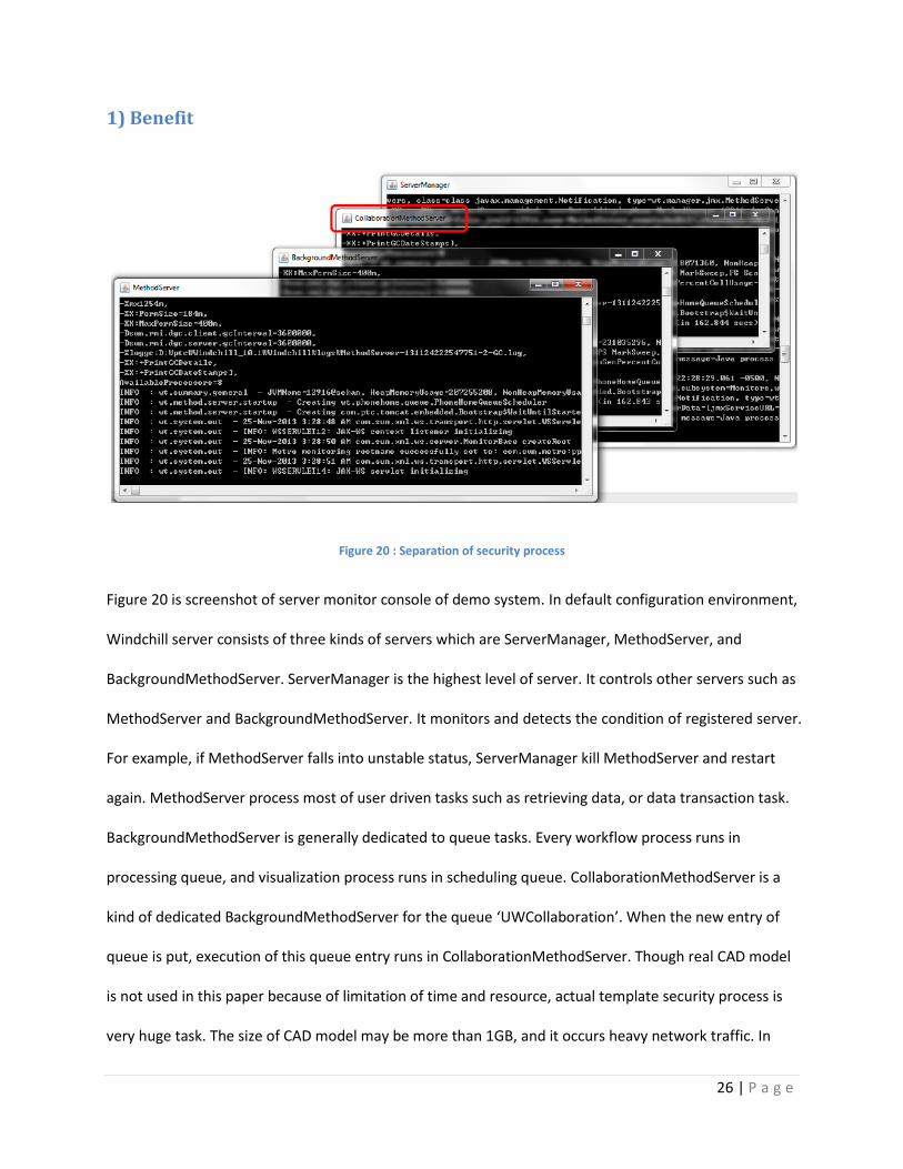
Figure 20 : Separation of security process
Figure 20 is screenshot of server monitor console of demo system. In default configuration environment,
Windchill server consists of three kinds of servers which are ServerManager, MethodServer, and
BackgroundMethodServer. ServerManager is the highest level of server. It controls other servers such as
MethodServer and BackgroundMethodServer. It monitors and detects the condition of registered server.
For example, if MethodServer falls into unstable status, ServerManager kill MethodServer and restart
again. MethodServer process most of user driven tasks such as retrieving data, or data transaction task.
BackgroundMethodServer is generally dedicated to queue tasks. Every workflow process runs in
processing queue, and visualization process runs in scheduling queue. CollaborationMethodServer is a
kind of dedicated BackgroundMethodServer for the queue ‘UWCollaboration’. When the new entry of
queue is put, execution of this queue entry runs in CollaborationMethodServer. Though real CAD model
is not used in this paper because of limitation of time and resource, actual template security process is
very huge task. The size of CAD model may be more than 1GB, and it occurs heavy network traffic. In

27 | P a g e
addition to file size, the number of CAD model in actual manufacturing environment is relatively huge.
This means template security process may cause serious damage to server, and sometimes may result in
entire system down. Therefore, separation of running server can be method of safety for system health
avoiding cascade catastrophes.
2) How it works
Separation of queue execution consists of following steps. First step is configuration of separated
BackgroundMethodServer. Second step is creation of dedicated queue, and the last put entry in that
queue.
2.1) Separation CollaborationMethodServer in existing BackgroundMethodServer
Figure 21 : Definition of CollaborationMethodServer for Security Process in cbsProject.xconf
Figure 21 shows the configuration file for setting CollaborationMethodServer separation. The key point
of this configuration is name of queue group which is ‘Collaboration’. Other configuration defines the
heap size, port number, etc.

28 | P a g e
2.2) Add dedicated queue
Figure 22 : Windchill Queue creation for Security Process
Figure 22 is the screenshot of creation for queue ‘UWCollaboration’. In above picture, the name of
group is mapped to the name of queue group in Figure 21.
2.3) Send task to dedicated queue
Figure 23 : Implementation Code of Calling Method for Dedicated Queue

29 | P a g e
Figure 23 is actual java code for putting entry in dedicated queue ‘UWCollaboration’. It is notable that
method ‘doSecurityJob’ is defined during putting entry. When ‘UWCollaboration’ queue executes its
entry, ‘doSecurityJob’ is called, and template security process is done in this method.
XV. ADMINISTRATION PAGES
In order to test core function of this system, creation and view the test data is necessary. Below pages
and figures show the detail function and its usage.
1) Main page for data creation and confirmation
Figure 24 : Administration Page Main
Figure 25 shows the main administration page. Main page list up all functionalities provided to manage
collaboration system data. From ‘EPM Document List’ to ‘Collaboration Policy List’, each link provides
listing up and creation function for each data entity. Remain threes deal with execution of distribution
and checking the result of distribution.

30 | P a g e
2) EPMDocument
Figure 25 : EPMDocument Management
Figure 26 represents all EPMDocument list in the system, and it provides brief information of
EPMDocument. As mentioned earlier, EPMDocument is core object of Windchill system; therefore, more
detail information of each EPMDocument can be given by OOTB EPMDocument information page. In this
picture, ‘primary content’ column is key column for testing and verifying EPMDocument security process.
Comparing original primary content and secured primary content can explain how the template security
process which is one of the two key features in this paper is possible.
Figure 26 : Create new EPMDocument
Creation of EPMDocument is generally integrated with CAD authoring tools such as Pro-Engineer, CATIA
in real case, but because CAD authoring tools could not be used, EPMDocument creation page was
implemented for replacing the functionality of CAD authoring tools. Primary content is mainly real CAD
file, but only text file is meaningful in this paper.

31 | P a g e
3) Template Element
Figure 27 : Template Element Management
Template elements can be defined as target elements need to be secured during collaboration. This
page lists up existing template elements in the system. Though corresponding post operation for each
template element during security processing is mostly complicated and needs CAD tool dependent
running environment in reality, these complex operations were simplified as content replacement of
simple text file in this paper. In other words, if template element is defined as Figure 27, expected result
will just modify add text message in primary content of original EPMDocument.
Figure 28 : Create new Template Element
Figure 28 is screenshot of template element creation page. Because element name is directly related
with template security processing, definition of element name should not be arbitrary. As a sample,
‘ANALYSIS_FEATURE’ and ‘TOLERANCE_ANALYSIS’ can be used in this project. Additional definition of

32 | P a g e
element name needs related implementation how to execute security process for newly added one.
Definitely, there are more cases in reality. Execute method is one of ‘REMOVE’ or ‘SIMPLIFY’. Target
group means the name of filtering group for applying security process. For example, assume
‘ANALYSIS_FEATURE’ element is important in ‘Cylinder Block’ design team, but it does not need to be
template element in ‘Transmission’ design team. For the same ‘ANALYSIS_FEATURE’ element, some
EPMDocuments needs security processing, and sometimes it’s not necessary.
4) Collaborator
Figure 29 : Collaborator Management
Figure 29 shows the lists of collaborator defined in the system. Collaborator can be different
department in the same company or different vendor. The exact meaning of collaborator is the data
receiver from main system. All defined collaborator will be the target of distribution if corresponding
collaborator policy exists.
Figure 30 : Create new Collaborator

33 | P a g e
Figure 30 shows the creation collaborator page. Indeed there are more attributes for defining
collaborator, but only 4 attributes were used for simplicity because target system in this paper is
dedicated to data distribution only.
5) Collaboration Policy
Figure 31 : Collaboration Policy Management
Collaboration policy defines the rule for gathering distribution data. Because the definition of policy is
related with real distributing action, policy ID should be defined with executable process so that it can
correlate with distribution implementation. In this paper, ‘ECN’, ‘PART’, ‘EPM’ are available choices.
Security check attributes determine whether injection of security process is needed or not. Though it is
meaningful in EPMDocument data only in current process definition, it is also available for ‘PART’ or
‘ECN’ if additional security process is defined later.
Figure 32 : Create new Collaboration Policy

34 | P a g e
Figure 32 shows the collaboration policy creation page, if value of security check is true, security process
is added during gathering distribution data. In the reverse case, target data itself will be distributed to
collaborator.
6) Collaborator Policy
Figure 33 : Collaborator Policy Management
Collaborator policy maps collaborator with collaboration policy. Figure 33 shows the mapped policy for
collaborator ‘VX_101’.
Figure 34 : Map Collaborator with Policy
Figure34 shows the collaborator policy creation page, and only pre-defined collaborator and policy is
listed up in select box.

35 | P a g e
XVI. TEST SCENARIO 1 – TEMPLATE SECURITY PROCESS
Template security process is content replacement handling for designated EPMDocument. Regardless of
distribution rule, all EPMDocuments which contains template element defined in ‘Template Element
Management’ must be processed before the state ‘PREPARE PUBLICATION’. The identifier whether
EPMDocument is template based model or not is designated attribute ‘TEMPLATE_BASED’ of
EPMDocument. If the value of ‘TEMPLATE_BASED’ is not null and not empty, EPMDocument is regarded
as template based model, and it means post template security process must be following during state
change.
1) Prepare Test EPMDocument
Figure 35 : Create test EPMDocument
In order to demonstrate the template security process, target EPMDocument has to be prepared. As
mentioned earlier, general EPMDocument creation process is automated by CAD tools check-in process.
If designer designs CAD model and he check-in that model into system, EPMDocument is created
automatically using designated attributes defined in CAD model. In this paper, however, integration with
36 | P a g e
CAD tools is out of scope; therefore, creation EPMDocument is replaced with customized function like
Figure 35. In this figure, ‘TEMPLATE_BASED’ attribute is ‘T’, and this means target EPMDocument needs
template security processing. In addition to ‘TEMPLATE_BASED’ attribute, ‘PRIMARY CONTENT’ is
another key attribute for demonstration. As mentioned in limitation of this paper, the file of ‘PRIMARY
CONTENT’ must be text formatted, and the rationale of this constraint is to verify the change of content
clearly. In above picture, original content of EPMDocument is just text file contains simple words.
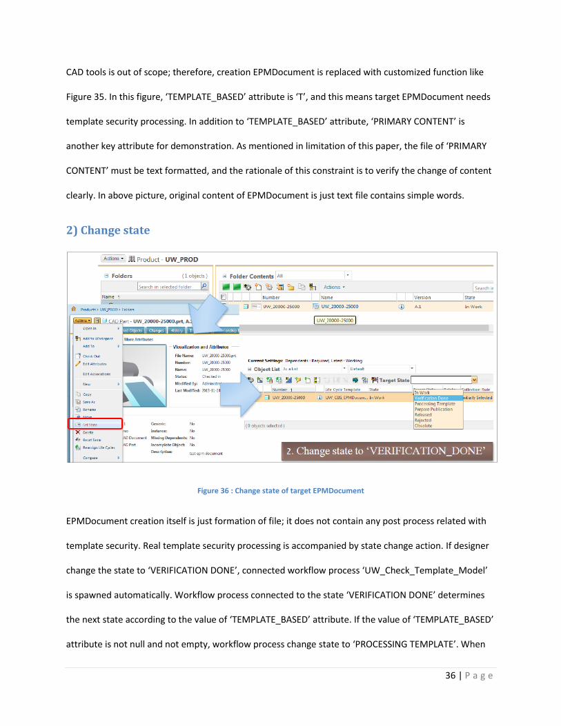
2) Change state
Figure 36 : Change state of target EPMDocument
EPMDocument creation itself is just formation of file; it does not contain any post process related with
template security. Real template security processing is accompanied by state change action. If designer
change the state to ‘VERIFICATION DONE’, connected workflow process ‘UW_Check_Template_Model’
is spawned automatically. Workflow process connected to the state ‘VERIFICATION DONE’ determines
the next state according to the value of ‘TEMPLATE_BASED’ attribute. If the value of ‘TEMPLATE_BASED’
attribute is not null and not empty, workflow process change state to ‘PROCESSING TEMPLATE’. When

37 | P a g e
the state of EPMDocument is changed to ‘PROCESSING TEMPLATE’, connected workflow
‘UW_TemplateProcess’ is spawned, and this workflow execute template security job. Figure 36 explains
how to change the state of EPMDocument.
3) View template process result
Figure 37 : Check Process Result
Figure 38 shows the result of template security process for EPMDocument ‘UW_20000-25000’. There
are three check points in this process. First, check separation of virtual machine for process is correct. In
this picture, there are execution logs of process, and target background method server is
‘CollaborationMethodServer’. As mentioned in separation dedicated queue chapter, separation of
running virtual machine is one of the key features in this paper, and this picture shows the result is the
same as expected one. Second, check new file named ‘{Original EPMDocument File Name}_TP’ is
created, and it is worthy of notice. The exact result of template security process is creating new
EPMDocument. Template security process does not change anything of original EPMDocument because
original must be managed by original designer continuously. Dual management for EPMDocument is key

38 | P a g e
aspect of this paper. Third, check the primary content is changed well by pre-defined template element
features. In above picture, pre-defined template feature is ‘ANALSYS_FEATURE’ and execute method is
‘REMOVE’. The content of processed EPMDocument contains the text ‘ANALSYS_FEATURE was removed’,
and this shows the result is the same as expected one.
XVII. TEST SCENARIO 2 – DISTRIBUTE PROCESS
1) Prepare Collaborator
Collaborator ID Collaborator Name Collaborator Type Collaborator Description
VX_101 Miss Fortune Third Vendor Wheel manufacturing vendor
Collaborator VX_101 was prepared for testing.
2) Create Collaboration Policy
Policy ID Policy Name Policy Description Security Check
EPM_Policy EPM Policy This policy describes the rule for distributing CAD
Document
True
ECN Engineering
Change Order
Policy
This policy describes the rule for distributing Change
Order Data.
False
There are two collaboration policies for testing. One is for ‘EPMDocument’, and the other is for
‘Engineering Change Notice’. In addition, EPMDocument policy will be followed by security process like
above table.

39 | P a g e
3) Create Collaborator Policy
Collaborator ID Policy ID
VX_101 ECN
VX_101 EPM_Security
There are two mappings for testing. Collaborator VX_101 has two policies which is for ECN and EPM
with Security.
4) Prepare target date for distribution
Figure 38 : Prepared Data for Testing Distribution
Figure 38 shows the administrative page which contains the target data and the way how to execute
distribution. There are three types of data in above picture, first is Engineering Change Order (Notice)
List, second is Part List, and third is EPMDocument List. All these data are objects are in ‘RELEASED’ state

40 | P a g e
in the system, and distribution of these data will be filtered by definition of collaborator and its policies.
The red boxed link ‘DO Distribute’ executes distribution.
5) Execute distribution
In figure 38, clicking the red boxed link executes distribution. In the target data, some data will be
distributed to target collaborator under the defined collaboration policies.
6) View distribution result
Checking result whether is valid or not consists of two steps; first is checking collaboration history data,
and second is checking sending to legacy data.
6.1) Check Collaboration History
Figure 39 : Result of Collaboration History
Figure 39 shows the collaboration history data for previous distribution. The execution of distribution
was processed on November 25, 2013 about collaborator VX_101 having two policies which are EPM
with security and ECN. Although the collaboration history is brief, this is key data for checking if
distribution was processed successfully or not.

41 | P a g e
6.2) Check Intermediate Data for Sending to Legacy
Figure 40 : Result of Send to Legacy
All distribution target data which are already filtered by collaboration policies is not directly sent to
collaboration system. These data is first moved to intermediate spaces, this is generally called interface
table. Figure 40 shows the intermediate table data to be sent by scheduler or manual processing. Of
course, moving from original system to collaborator system is out of scope, but above picture can prove
enough how distribution process is done. Because VX_101 has policies about EPMDocument and ECN,
there is no Part data, and it is notable to check the EPMDocument number in EPMDocument List. The
target EPMDocument is ‘UW_20000-25000_TP’, and suffix ‘_TP’ means that target data is secured
EPMDocument.
XVIII. CONCLUSION
Security is one of the biggest hot topics these days, and most outflows of industry technology result
from human fallacies pursuing unfair profits. These security affairs can be less if system can support

42 | P a g e
basic protection functions. Template security process topic mentioned in this paper is about security
protection activities, it focuses on CAD content security. Though proof of concept for template security
process is shown without actual CAD file demonstration, design and implementation of concept can
show enough how this approach operates. In addition, policy based collaboration method in this paper
aim at light-weight service than existing products. Furthermore, collaboration approach in this paper
assumes existence of legacy system, and prepares intermediate spaces before actual distribution. This
means that It can be applicable to any platform of collaborator environment because it provides the
data as common relational database table format which can be accessed in various way. Definitely,
when more tight management of collaborating environment is needed, commercial products can be
better choice.
XIX. REFERENCE
[1] 3HTI, “Windchill®Supplier Management Solution”. Retrieved from http://www.3hti.com/wp-
content/uploads/datasheets/Windchill-Supplier-Management-Datasheet-3HTI.pdf
[2] Automotive News, “Suppliers to the 2013 Hyundai Santa Fe” April 2013. Retrieved from
http://www.autonews.com/article/20130408/CUTAWAY/130409921/suppliers-to-the-2013-
hyundai-santa-fe#axzz2llXwggCn
[3] Cera, C. D., Kim, T., Braude, I., Han, J., & Regli, W. C. (2004). Hierarchical role-based viewing for multi-
level information security in collaborative CAD (No. DU-CS-04-01). DREXEL UNIV PHILADELPHIA PA
DEPT OF COMPUTER SCIENCE.
[4] Cisco, “Cisco Distributed Research and Development Solution Deployment Guide for PTC Windchill”.
Retrieved from
http://www.cisco.com/en/US/docs/solutions/Verticals/Distributed_RD/dist_rd.html#wp67954

43 | P a g e
[5] Dannenberg, J., & Kleinhans, C. (2004). The coming age of collaboration in the automotive industry.
Mercer Management Journal, 17, 88-94.
[6] G. Sudhir, GRABCAD, “Tutorial - Relations in Pro Engineer Wildfire aka Creo Elements Pro? ” Feb 2011.
Retrieved from http://grabcad.com/questions/tutorial-relations-in-pro-engineer-wildfire-aka-
creo-elements-pro
[7] S. Oleg, Beyond PLM, “Aras PLM lines up against Windchill, Enovia, and TeamCenter” May 2011.
Retrieved from http://beyondplm.com/2011/05/07/aras-plm-lines-up-against-windchill-enovia-
and-teamcenter/


