55
Design Concept of the facilities to manage river or to occupy the River manage river or to occupy the River space Kamoto Minoru Chief Researcher ICHARM/PWRI ICHARM/PWRI 1

Design Concept of the facilities to manage river or to occupy the Rivermanage river or to occupy the River
space
Kamoto MinoruChief ResearcherICHARM/PWRIICHARM/PWRI
1

ContentsContents
• Names of the river• Dike, inspection passage, super leveeDike, inspection passage, super levee• Revetment, gabion, riprap• Groundsill• Sluice waySluice way• Weir• Bridge
2

ReferenceReference
• Ministry of Land Infrastructure Transport and Tourism Ordinance for Structural Standards of River Administration Facilities (STRUCTURAL RULES) JapanRULES), Japan
• River and Dam Technical Standards, Japan
3

Names of the riverNames of the river
FreeboardDHWL
Riverside landRight side
Protected landLeft side
Protected Land
River Conservancy
Protected landProtected Land
2 3 1 3 2
River Area River Conservancy Area
1 Low water bed, Low‐flow Channel
2 Base of Dike
3 High water bed, River terrace
4

Koisegawa Yasato IbarakiKoisegawa, Yasato, Ibaraki, Japan
5
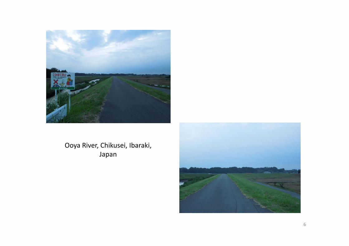
Ooya River, Chikusei, Ibaraki, Japan
6

DikeDike
• A dike is an embankment or levee constructed along the banks of a stream, river, lake or gother body of water for the purpose of protecting from overflowing floodwater byprotecting from overflowing floodwater by confining the stream flow in the regular channel River improvement should bechannel. River improvement should be planned with non‐diked river if possible to have efficient drainage conveyance.
7

RIVERSIDE LANDSIDE
Freeboard
Dike Crest ShoulderShoulderRIVER SIDE LAND SIDE
DFL Freeboard
Slope
Slope Ground LevelDike Height
S
Toe of Dike Slope
Base of DikeToe of Dike Slope
Parts of DikeParts of Dike8
1
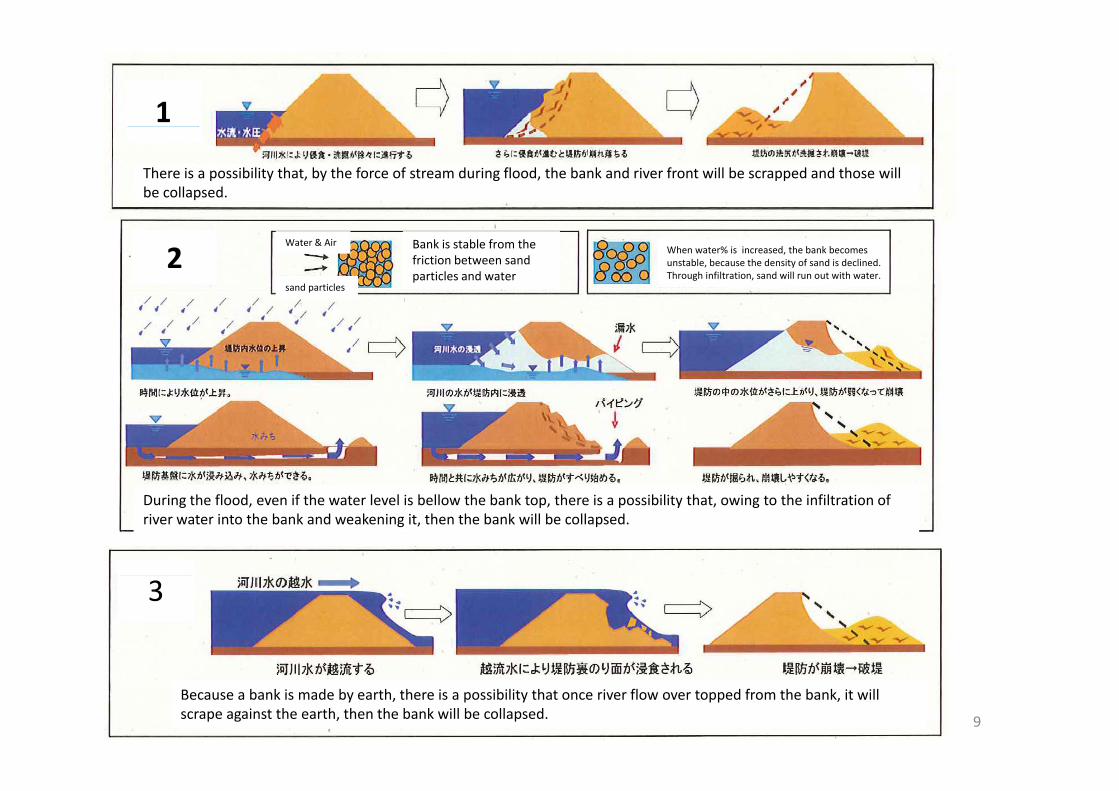
There is a possibility that, by the force of stream during flood, the bank and river front will be scrapped and those will be collapsed.
2 Bank is stable from the friction between sand particles and water
When water% is increased, the bank becomes unstable, because the density of sand is declined. Through infiltration, sand will run out with water.
Water & Air
sand particles
During the flood, even if the water level is bellow the bank top, there is a possibility that, owing to the infiltration of river water into the bank and weakening it, then the bank will be collapsed.
3
9
Because a bank is made by earth, there is a possibility that once river flow over topped from the bank, it will scrape against the earth, then the bank will be collapsed.

2:11
2 :
22
Minimum Slope of Dike
10

Mild Slope Levee at Shinanogawa in Nagaoka City
11

Design flood discharge Freeboard g g
Q3
(m)
(m3/s)
Less than 200 0.6
200 and up to 500 0.8
500 and up to 2 000 1 0500 and up to 2,000 1.0
2,000 and up to 5,000 1.2
5,000 and up to 10,000 1.5
10 000 and over 2 010,000 and over 2.012

Design flood discharge, Q Crest Width g g , Q(m3/sec) (m)
Less than 500 3Less than 500 3500 and up to 2,000 42 000 d t 5 000 52,000 and up to 5,000 55,000 and up to 10,000 610,000 and over 7
13

Impervious Type Revetment(W t bbl )
Pervious soil or dryrubble masonry
Toe Drain
(Wet rubble masonry) rubble masonry
Seepage line
Drain
Dike: Example of Countermeasure Against Seepage
14
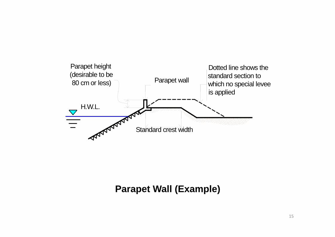
P t h i htParapet height(desirable to be 80 cm or less) Parapet wall
Dotted line shows the standard section towhich no special leveeis applied
H.W.L.
is applied
Standard crest width
Parapet Wall (Example)
15

Gogyo River, Chikusei city, Ibaraki, Japan 2013 Sep. 7th
16

A b id (i l di ti t) h ll bA bridge (including connection part) shall be a structure which will not hinder the structure of inspection passage.
17

Water pipe bridge at Kokai River2013 Sep. 7th
18

19

M t M ilMetro ManilaTullahan River
20

Super Levee 21

RevetmentRevetment
• Function of revetment is to protect the collapse of riverbank due to erosion, scouring p gand/or riverbed degradation.
22

Slope covering workTransition work(Gabion Mattress)
Flow Di
End protectionworkDirection
Foundationwork (cut-off walls)
Foot Protectionwork (apron)
Components of Revetment
23
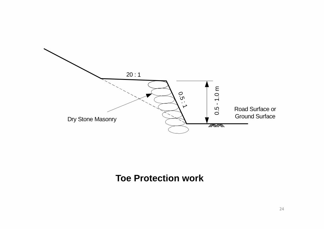
20 : 1
m0.5 : 1
Road Surface orG d S f0.
5 - 1
.0 m
Ground Surface0
Dry Stone Masonry
Toe Protection work
24
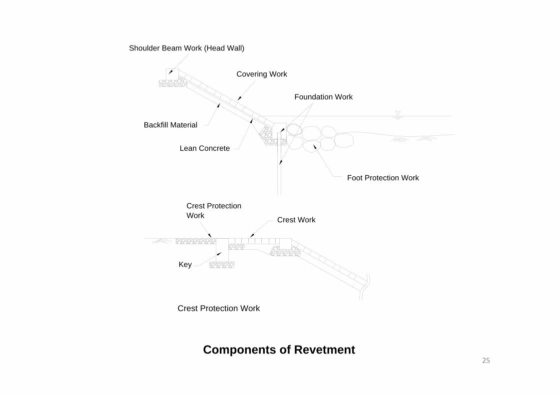
Shoulder Beam Work (Head Wall)
Foundation Work
Covering Work
Lean Concrete
Backfill Material
Foot Protection Work
Crest ProtectionWork Crest Work
Key
Crest Protection Work
Components of Revetment25
• Gabions (from Italian gabbionemeaning "big cage"; from Italian gabbia and Latin caveameaning "cage") are cages, cylinders, or boxes filled with rocks, concrete or sometimes sand and soil that are used in civil
i i d b ildi d ilit li tiengineering, road building, and military applications. For erosion control caged riprap is used. For dams or foundation construction cylindrical metal structuresfoundation construction, cylindrical metal structures are used. In a military context, earth or sand‐filled gabions are used to protect artillery crews from enemy fire.
• (From Wikipedia, the free encyclopedia)
26

27

• Riprap also known as rip rap rubble shot rock• Riprap—also known as rip rap, rubble, shot rock, rock armour or Rip‐rap—is rock or other material used to armor shorelines streambeds bridgeused to armor shorelines, streambeds, bridge abutments, pilings and other shoreline structures against scour water or ice erosionagainst scour, water or ice erosion.
• It is made from a variety of rock types, commonly granite or limestone and occasionally concretegranite or limestone, and occasionally concrete rubble from building and paving demolition. It can be used on any waterway or watercan be used on any waterway or water containment where there is potential for water erosionerosion.
• From Wikipedia, the free encyclopedia
28

29

Spur DikeSpur Dike
• A spur dike is a river structure with the following functions :1) To increase as the flow roughness and to reduce the flow velocity around the riverbank.reduce the flow velocity around the riverbank.2) To redirect river flow away from the riverbank.
• Based on the above functions, the spur dikes are installed with the following purposes:1) To prevent bank erosion and damage to revetment.2) To deepen water depth for navigation.) p p g
30

DeflectedUpstream
At right angles
Overflow Type
Overflow and Non - overflow
spur
yp Type
Flow Direction- Sedimentation Area
- Scouring Area
31
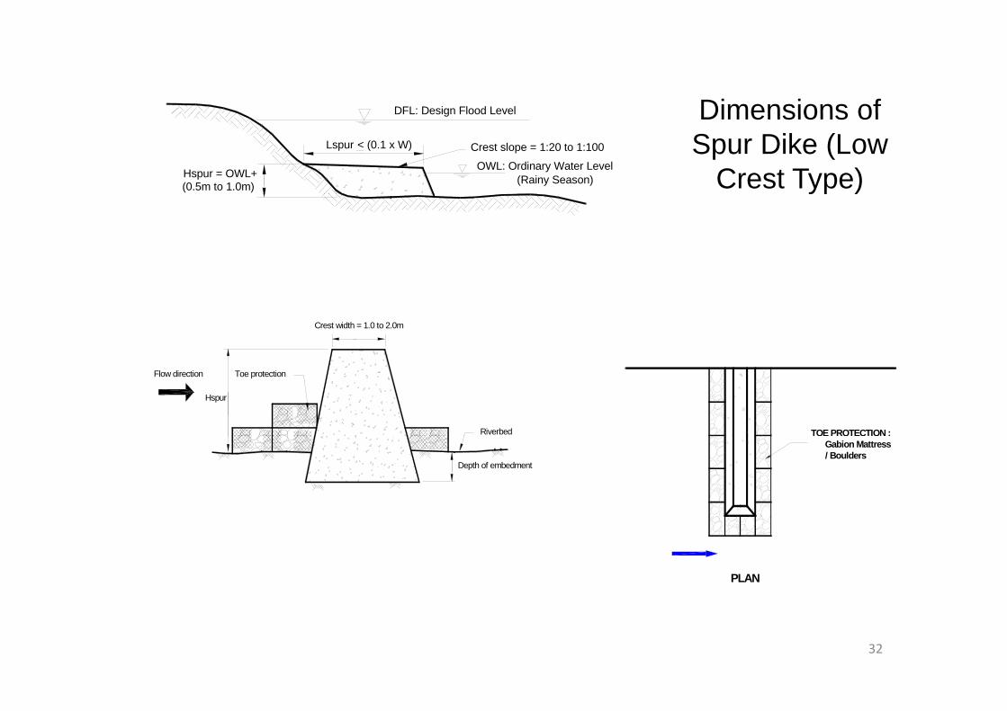
DFL: Design Flood Level Dimensions ofDFL: Design Flood Level
Crest slope = 1:20 to 1:100
OWL: Ordinary Water Level
(0.5m to 1.0m) (Rainy Season)
Lspur < (0.1 x W)
Hspur = OWL+
Dimensions of Spur Dike (Low
Crest Type)y )
Crest width = 1.0 to 2.0m
TOE PROTECTION :Riverbed
Toe protection
Hspur
Flow direction
Gabion Mattress / Boulders
Depth of embedment
PLAN
32

GROUNDSILL
• A groundsill is a river structure to prevent the riverbed degradation, to stabilize the riverbed gand to maintain the longitudinal and cross‐sectional profilessectional profiles.
33

Designed RiverbedBed protection (upstream)W.S.
g
ExistingRiverbedBedprotection2 meters ( ) Existing RiverbedBed protection,
soft type like gabionApron
(Max.)
Bed protection,hard type, like concrete
Cut-off wall, to prevent pipingyp ,
GROUNDSILLGROUNDSILL
34
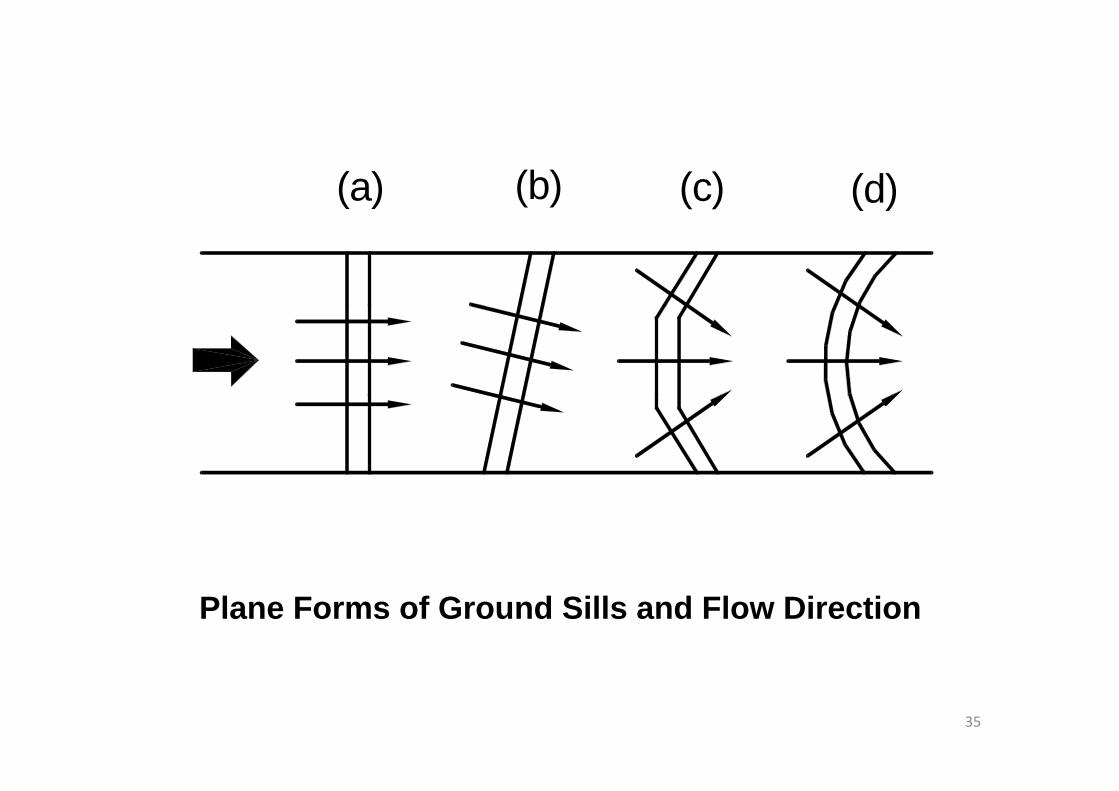
(a) (b) (c) (d)
Plane Forms of Ground Sills and Flow Direction
35

Sluice WaySluice Way
• Sluiceway is a structure that connects the culvert passing through the dikes and its gate.p g g gSluiceway is categorized into two (2) types according to its purpose: one is to drain theaccording to its purpose: one is to drain the inland water into river, and the other is to draw the water (as an intake structure) fromdraw the water (as an intake structure) from the river for irrigation use or some other purposes.
36

Design Flood Level
Gate Drainage
Sluiceway for Drainage
37

Kokai River from MLIT office
38

WEIRWEIRb i i d i d t lt th fl• a barrier across a river designed to alter the flow
characteristics. In most cases, weirs take the form of a barrier, smaller than most conventional dams, across a , ,river that causes water to pool behind the structure and allows water to flow over the top. Weirs are commonly used to alter the flow regime of the rivercommonly used to alter the flow regime of the river, prevent flooding, measure discharge and help render a river navigable.
• The weir is classified into an intake weir, diversion weir, tide weir, etc., and it is further classified into fixed weirs and movable weirs according to the weir’sweirs, and movable weirs according to the weir s intended purpose.
39

• (1) Weir is a structure which safeguards the action of water flow at a level equal to or loweraction of water flow at a level equal to or lower than the design high‐water level (or the design high‐tide level in case of the high‐tide section)high‐tide level in case of the high‐tide section).
• (2) The flow of flood at a water level equal to or lower than the design high water level and thelower than the design high‐water level and the adjacent river bank and the structure of river facilities should not be hindered by the weirfacilities should not be hindered by the weir.
• (3) It shall be designed in consideration of prevention of scour in river bed which connectsprevention of scour in river bed which connects to the weir.
40

Aoki Weir
Photos in 2013 Sep 10
Location Sakuragawa City, Ibaraki, JapanLocation Sakuragawa City, Ibaraki, JapanName of river SakuraBeneficial area 61 haHeight of the weir 5 mgManager of Facility Yamato & Sakura Water Supply AssociationLength of the weir 19 mStyle of the weir Semi Fixed Weir (Steel Slide Gate)
41
Style of the weir Semi Fixed Weir (Steel Slide Gate)Construction year 1998

Hojo Weir
Location Tsukuba CityPhoto in 2013 Sep 10 2013 Oct. 19
Location Tsukuba CityName of river SakuraBeneficial area 231.8 haHeight of the weir 3.1 mgManager of Facility Tsukuba City Land Improvement
OrganizationLength of the weir 36.3 mStyle of the weir Inflatable Rubber WeirConstruction year 1999
42

Design flood discharge Span length (m)
(m3/sec)
Less than 500 15
500 and up to 2,000 20
2,000 and up to 4,000 30
4,000 and over 40
43

The Impact of structures within the river on flood flow.
Taunsa Barrage in Pakistan Completed in 1958, rehabilitation from 2003 to suply irrigation for 8000km2. 65 Gates (including p y g ( grocks) Width 1325m
1. Review the infrastructures within the rivere e e as uc u es e e2. Width of Natural river and flow discharge volume3. The level of river water upstream and downstream of the structure.4 Erosion and Accretion in the vicinity of the structure
44
4. Erosion and Accretion in the vicinity of the structure5. Emergency discharge release 6. Identify the issues of designing structures within the river

BridgeBridge• A structure built to span a river for the purpose of providing
itpassage over it.• (1) Abutment and pier to be built within the river area shall be
a structure which will be safe against the action of river flow gat a water level equal to or lower than the design water level (or the design high tide level in a high tide section).
• (2) Abutment and pier shall not disturb the flood flow at a• (2) Abutment and pier shall not disturb the flood flow at a water level equal to or lower than the design high water level.
• (3) They shall not severely hinder the structure of adjacent river banks and facilities.
• (4) And they shall be designed in consideration of prevention of scour in river bed adjoining the abutment or the pierof scour in river bed adjoining the abutment or the pier.
45

Abutment
FreeboardCrest Width Crest WidthFreeboard
Bank
Usually, depth ratio is 1/(18‐20). Be careful for high banking in soft
Depth
Sground Span
46

Bridge at Koise Gawa, Yasato, Ishioka City
47
g , , yIbaraki Prefecture, Japan

Pier
Position of Piers
In case Design Discharge Q≦500 m3/sQ≦500 m /s
10m can be reduced to 5 mPier can be positioned Pier cannot
be positioned
Depth of footingDepth of footing
More than 2m score is
More than 2mMore than 1m
More than 2m score is found, below the planned level or deepest score level
48
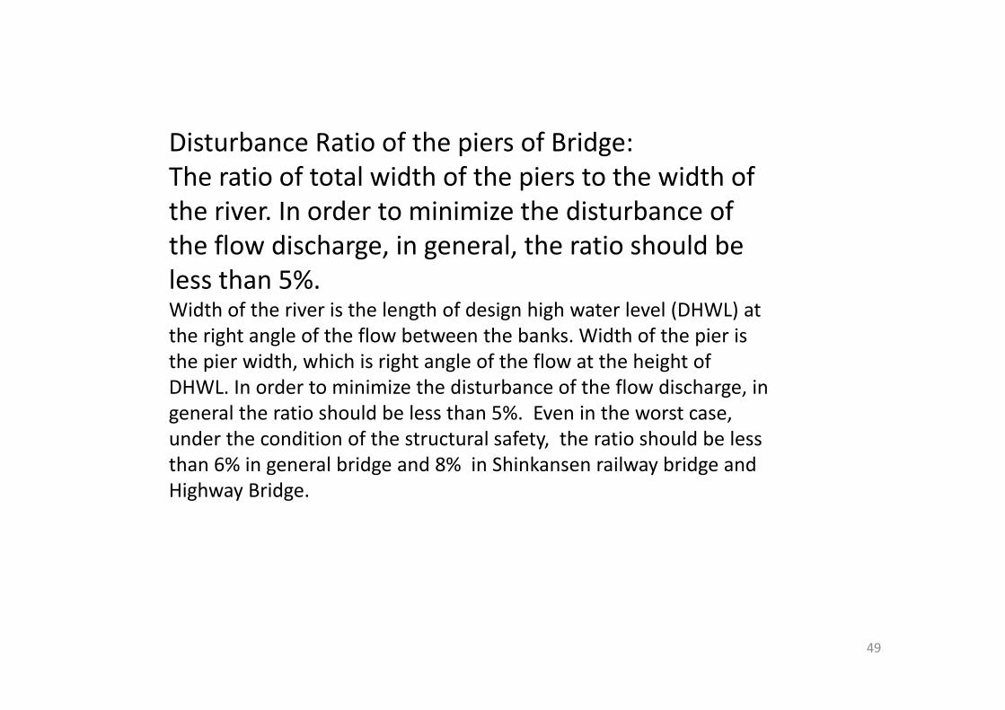
Disturbance Ratio of the piers of Bridge:The ratio of total width of the piers to the width of the river. In order to minimize the disturbance of the flow discharge, in general, the ratio should be l th 5%less than 5%. Width of the river is the length of design high water level (DHWL) at the right angle of the flow between the banks. Width of the pier is h i id h hi h i i h l f h fl h h i h fthe pier width, which is right angle of the flow at the height of DHWL. In order to minimize the disturbance of the flow discharge, in general the ratio should be less than 5%. Even in the worst case, under the condition of the structural safety the ratio should be lessunder the condition of the structural safety, the ratio should be less than 6% in general bridge and 8% in Shinkansen railway bridge and Highway Bridge.
49

Ooya River, Chikusei City
50Gogyo River, Chikusei City
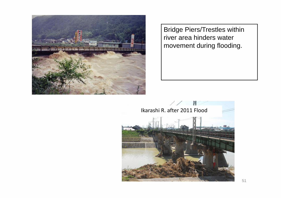
Bridge Piers/Trestles withinBridge Piers/Trestles within river area hinders water movement during flooding.
Ikarashi R. after 2011 Flood
51

L : Length between the piers or abutment (Between front of the Abutment to middle of the pier
or between middle of the piers)
To have great impact for RiverTo have great impact for River Management
YesNo
L ≧ 20 + 0.005QQ ≧ 500 m^3/sYesYes
No
L ≧20m Width of the River≧30m
L≧15L≧12 5 m
YesNo
L ≧15m L ≧12.5 m
52
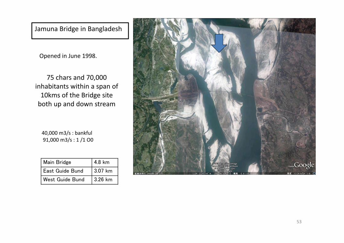
Jamuna Bridge in Bangladesh
Opened in June 1998.
75 chars and 70,000 inhabitants within a span of 10kms of the Bridge site10kms of the Bridge site both up and down stream
40,000 m3/s : bankful91,000 m3/s : 1 /1 O0
Main Bridge 4.8 km
East Guide Bund 3.07 km
West Guide Bund 3.26 km
53

During Construction Changed the design ofDuring Construction, Changed the design of Guide bund Slope at Jamuna Bridge in
Bangladesh
Sirajiganji
Bhuapur
Sand bar
Hard point
Hard point
Spur
SpurSpur
road
Guide Bund
Bridge
54
Reclaimed area

Thank for your attentiony
Please referPlease refer http://whrm‐kamoto.com/top.html
Philippines: Design Standard Guideline
55


