HAL Id: hal-01236568 https://hal.archives-ouvertes.fr/hal-01236568 Submitted on 1 Dec 2015 HAL is a multi-disciplinary open access archive for the deposit and dissemination of sci- entific research documents, whether they are pub- lished or not. The documents may come from teaching and research institutions in France or abroad, or from public or private research centers. L’archive ouverte pluridisciplinaire HAL, est destinée au dépôt et à la diffusion de documents scientifiques de niveau recherche, publiés ou non, émanant des établissements d’enseignement et de recherche français ou étrangers, des laboratoires publics ou privés. Design Configurations and Creation of Lattice Structures for Metallic Additive Manufacturing Abdul Hadi, Frédéric Vignat, François Villeneuve To cite this version: Abdul Hadi, Frédéric Vignat, François Villeneuve. Design Configurations and Creation of Lattice Structures for Metallic Additive Manufacturing. 14ème Colloque National AIP PRIMECA, Mar 2015, La Plagne, France. hal-01236568
Transcript
HAL Id: hal-01236568https://hal.archives-ouvertes.fr/hal-01236568
Submitted on 1 Dec 2015
HAL is a multi-disciplinary open accessarchive for the deposit and dissemination of sci-entific research documents, whether they are pub-lished or not. The documents may come fromteaching and research institutions in France orabroad, or from public or private research centers.
L’archive ouverte pluridisciplinaire HAL, estdestinée au dépôt et à la diffusion de documentsscientifiques de niveau recherche, publiés ou non,émanant des établissements d’enseignement et derecherche français ou étrangers, des laboratoirespublics ou privés.
Design Configurations and Creation of LatticeStructures for Metallic Additive Manufacturing
Abdul Hadi, Frédéric Vignat, François Villeneuve
To cite this version:Abdul Hadi, Frédéric Vignat, François Villeneuve. Design Configurations and Creation of LatticeStructures for Metallic Additive Manufacturing. 14ème Colloque National AIP PRIMECA, Mar 2015,La Plagne, France. �hal-01236568�
Abstract— Additive manufacturing brings a whole new world of opportunities and changes in manufacturable parts. These changes include the capability to manufacture architectured materials. This paper focuses on the types of periodic lattice structures in designing metallic additive manufacturing parts. The different configurations and its’ designs. The outcome of this study will serve as a basis and pre-study to help the creation of CAD assistive tools and libraries to design lattice structure.
Additive manufacturing creates new possibilities in free form design[1]. For example, the creation of lattice structures. The realization of lattice structures is no longer limited by conventional manufacturing constraints [2][3]. These lattice structure parts can be categorized as architectured materials. There are various types of lattice structures. Depending on its’ configurations, each one has its’ own characteristics and application.
Due to the different mechanical properties and attributes that these structures bring, architectured materials can be defined as a new material. Therefore, it is very beneficial to use architectured materials in additive manufacturing parts. For example, it enables engineers to design lightweight structures by incorporating lattice structures in the parts manufactured[3] and also improve system performances [4], for example heat dissipation [5] and good acoustic insulation [6]. These parts can be used for end-user technical components and no longer just prototypic parts [2].
This paper focuses on defining the configurations of lattice structures and the input and output information to define each model. It also focuses on the characteristics of each type and how each part can be adapted and fine-tuned to reach specific requirements. These possibilities are unlimited, so the paper will only discuss on the most commonly used lattice structures and purposes.
The outcome of this study will serve as a basis and pre-study to help the creation of CAD assistive tools, libraries to design lattice structures and Additive Manufacturing file format. A study has shown that current CAD tools are not well
adapted to design lattice structures easily and quickly [7]. New assistive tools and file formats need to be created for additive manufacturing.
II. ARCHITECTURED MATERIALS FOR METALLIC ADDITIVE
MANUFACTURING
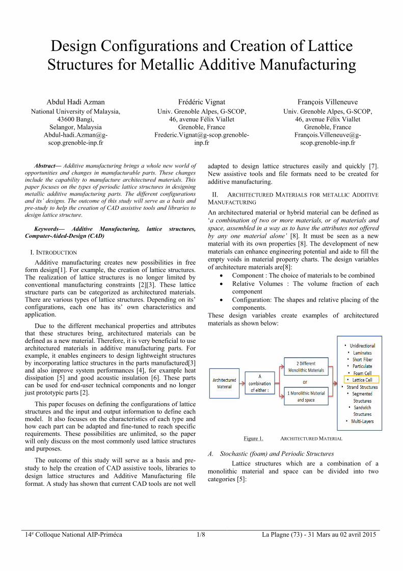
An architectured material or hybrid material can be defined as ‘a combination of two or more materials, or of materials and space, assembled in a way as to have the attributes not offered by any one material alone’ [8]. It must be seen as a new material with its own properties [8]. The development of new materials can enhance engineering potential and aide to fill the empty voids in material property charts. The design variables of architecture materials are[8]:
Component : The choice of materials to be combined Relative Volumes : The volume fraction of each
component Configuration: The shapes and relative placing of the
components. These design variables create examples of architectured materials as shown below:
Figure 1. ARCHITECTURED MATERIAL
A. Stochastic (foam) and Periodic Structures
Lattice structures which are a combination of a monolithic material and space can be divided into two categories [5]:
14e Colloque National AIP-Priméca 2/8 La Plagne (73) - 31 Mars au 02 avril 2015
Stochastic (foam) structures Periodic structures
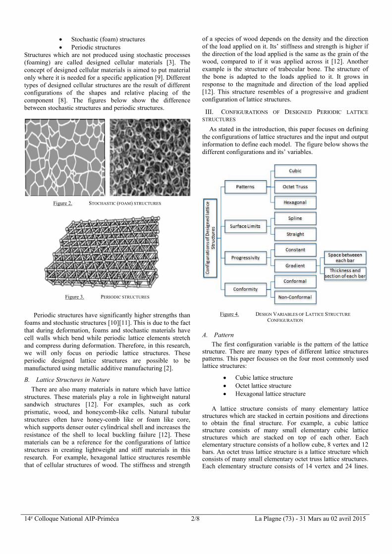
Structures which are not produced using stochastic processes (foaming) are called designed cellular materials [3]. The concept of designed cellular materials is aimed to put material only where it is needed for a specific application [9]. Different types of designed cellular structures are the result of different configurations of the shapes and relative placing of the component [8]. The figures below show the difference between stochastic structures and periodic structures.
Figure 2. STOCHASTIC (FOAM) STRUCTURES
Figure 3. PERIODIC STRUCTURES
Periodic structures have significantly higher strengths than
foams and stochastic structures [10][11]. This is due to the fact that during deformation, foams and stochastic materials have cell walls which bend while periodic lattice elements stretch and compress during deformation. Therefore, in this research, we will only focus on periodic lattice structures. These periodic designed lattice structures are possible to be manufactured using metallic additive manufacturing [2].
B. Lattice Structures in Nature
There are also many materials in nature which have lattice structures. These materials play a role in lightweight natural sandwich structures [12]. For examples, such as cork prismatic, wood, and honeycomb-like cells. Natural tubular structures often have honey-comb like or foam like core, which supports denser outer cylindrical shell and increases the resistance of the shell to local buckling failure [12]. These materials can be a reference for the configurations of lattice structures in creating lightweight and stiff materials in this research. For example, hexagonal lattice structures resemble that of cellular structures of wood. The stiffness and strength
of a species of wood depends on the density and the direction of the load applied on it. Its’ stiffness and strength is higher if the direction of the load applied is the same as the grain of the wood, compared to if it was applied across it [12]. Another example is the structure of trabecular bone. The structure of the bone is adapted to the loads applied to it. It grows in response to the magnitude and direction of the load applied [12]. This structure resembles of a progressive and gradient configuration of lattice structures.
III. CONFIGURATIONS OF DESIGNED PERIODIC LATTICE
STRUCTURES
As stated in the introduction, this paper focuses on defining the configurations of lattice structures and the input and output information to define each model. The figure below shows the different configurations and its’ variables.
Figure 4. DESIGN VARIABLES OF LATTICE STRUCTURE
CONFIGURATION
A. Pattern
The first configuration variable is the pattern of the lattice structure. There are many types of different lattice structures patterns. This paper focusses on the four most commonly used lattice structures:
A lattice structure consists of many elementary lattice
structures which are stacked in certain positions and directions to obtain the final structure. For example, a cubic lattice structure consists of many small elementary cubic lattice structures which are stacked on top of each other. Each elementary structure consists of a hollow cube, 8 vertex and 12 bars. An octet truss lattice structure is a lattice structure which consists of many small elementary octet truss lattice structures. Each elementary structure consists of 14 vertex and 24 lines.
14e Colloque National AIP-Priméca 3/8 La Plagne (73) - 31 Mars au 02 avril 2015
This figure below shows an elementary cubic and octet truss lattice structure.
Figure 5. ELEMENTARY CUBIC, OCTET TRUSS AND HEXAGONAL
LATTICE STRUCTURE
Many elementary lattice structures are positioned to obtain a full sized lattice structure. For example in the figures below:
Figure 6. CUBIC AND OCTET TRUSS LATTICE STRUCTURE
Figure 7. HEXAGON UNIT LATTICE STRUCTURE
B. Surface Limits
The surface limits variable can be divided into 3 categories:
Regular shaped structure with no outer boundary limits.
Boundary limited by a flat surface Boundary limited by a spline surface
These lattice structures can be designed and manufactured
in accordance to complex curvatures and tailored to the constraints of the parts’ functional surface.
Figure 8. LATTICE STRUCTURE LIMITED TO A FLAT SURFACE
Figure 9. LATTICE STRUCTURE LIMITED TO A SPLINE
C. Progressivity
Lattice structures can be uniform or gradient. For uniform lattice structures, the size and dimensions of each elementary structure are constant throughout the whole part. As for gradient lattice structures, the dimensions of each elementary lattice structure and the section of the bars vary throughout the part. A gradient lattice structure changes the density of the part. This ability to optimize the architectured lattice structure using gradient structures creates different densities in each area of the part. With the same material, a lattice with higher density will have higher strength and stiffness, but will add more mass to the overall part. By locally optimizing the properties of the architectured structure, it is possible to meet the requirements of specific application of forces in the area of a part.
This gradient form can be oriented to follow the
direction and magnitudes of the forces applied to the part and obtain the part’s required strength and stiffness. In areas where high stress is applied, a higher density architectured lattice structure will be needed. Therefore, smaller size elementary lattice structures with increased thickness of the bars are designed in this area to increase its’ strength and stiffness. While in areas where only a small amount of stress is applied, less dense lattice structures are needed. These figures below are examples of uniform and gradient lattice structures:
Figure 10. PROGRESSIVE SPACING BETWEEN EACH BARS
Figure 11. PROGRESSIVE THICKNESS AND SPACING BETWEEN EACH BAR
14e Colloque National AIP-Priméca 4/8 La Plagne (73) - 31 Mars au 02 avril 2015
D. Conformity
Architectured lattice structures can follow different shapes and surfaces, conforming to spline or flat surfaces. This characteristic is categorized as conformal lattice structures. Conformal lattice structures are oriented in accordance to the form and direction of the part’s surface. Whereas non-conformal lattice structures are oriented and positioned independently with the form of the part’s surface.
Figure 12. CONFORMAL LATTICE STRUCTURE
Figure 13. NON-CONFORMAL LATTICE STRUCTURE
IV. PROPOSED METHODOLOGY TO CREATE LATTICE
STRUCTURE MODELS
In this section, the proposed methodology to create lattice structure models is presented by (i) identifying the problems and limits of previous design methods and by (ii) using the Input-Process-Output approach.
A. Problems and Limits of Previous Design Methods
A lattice structure can be represented in a CAD software by its’ surfaces and forms. In previous design methods using current CAD software, the method would be to create an elementary lattice structure and repeat it along the X, Y and Z axis. However, as studies have shown, this would not only be a time consuming method, but it is also not suitable to represent the forms and surfaces of the lattice structure in CAD software due to the large number of forms involved [7]. Therefore, in this paper, the proposed design method is to create and represent only the point and line elements of the lattice structure.
B. Proposed Methodology
1) Input-Process-Output Approach
The input-process-output model describes the information process for the creation of lattice structure models. A program or process using the input-process-output model receives input
from the user, does some computations on the inputs, and returns the results of the computations. This approach is used in the proposed method to create the lattice structures. The input data is the information entered by the user via the Lattice Structure Generator interface as shown in figure 16. Processing takes place in the program of the generator. Output is the processed information generated by the program. The outcome is usable output information to represent and generate the lattice structure.
Figure 14. INPUT-PROCESS-OUTPUT APPROACH
The proposed methodology is to create and represent only the points and lines linking each point of the lattice structure without creating its surface forms. The output information is a text file which a viewer and CAD software interprets for visualization. The CAD software represents the lattice structure with an image or texture to avoid the need to create the forms’ surfaces in the CAD software.
2) Input Data and Output Information In the proposed idea, the input data consists of the
configuration design variables of the lattice structures. These variables determine and define the types and models of the lattice structure. During the design phase, the design variables are chosen to create a lattice structure which meets the functional requirements of the parts. The output information is the information which contains information of the lattice structure in readable text file format. This information is then imported and visualized in a viewer. The figure below shows the input data and output information.
Figure 15. INPUT DATA AND OUTPUT INFORMATION
The table below describes each input variable in detail: N° Input Description Value
14e Colloque National AIP-Priméca 5/8 La Plagne (73) - 31 Mars au 02 avril 2015
The table below describes each output information in detail: N° Output Description
1 Number of Points
2 Number of Lines
3 Co-ordinates of each point
4 Lines linking each point
Tableau 2. OUTPUT VARIABLE DISCRIPTION
This figure below is the Lattice Structure Generator interface in which the input data is entered. From the input data inserted, the program processes the information to create the output information using an algorithm which is explained in the next section.
Figure 16. LATTICE STRUCTURE GENERATOR INTERFACE TO CREATE
LATTICE STRUCTURES
The output information is a VTK file format. The Visualization Toolkit (VTK) file format is a readable text file which contains datasets for computer graphics. It provides a simple method to communicate data between software. It consists of five basic parts:
File version and identifier Header File format Dataset Structure Dataset attributes
Below is an example of a VTK file for a cubic lattice
structure. On the left are the X, Y, Z coordinates of each point. On the right are the lines which connect each point. From the input given, the task will be to obtain the coordinates of the points and the lines linking them as shown above.
Figure 17. OUTPUT INFORMATION
The VTK file output information is imported in a viewer software such as Paraview. The viewer processes the information and generates from the file a lattice structure.
Figure 18. VISUALIZATION OF VTK FILE OUTPUT INFORMATION IN A
VIEWER
From the different input variables in the table 1, the table below shows the amount of different lattice structure types that can be made from all the configuration variables.
Figure 19. NUMBER OF POSSIBLE DIFFERENT LATTICE STRUCTURE
CONFIGURATIONS
14e Colloque National AIP-Priméca 6/8 La Plagne (73) - 31 Mars au 02 avril 2015
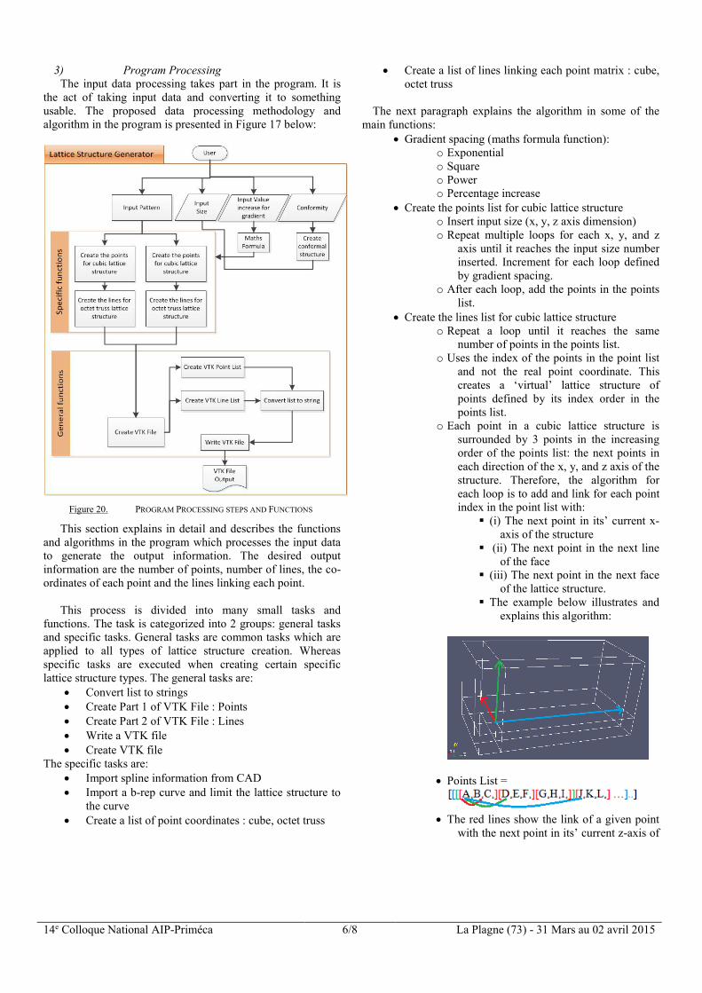
3) Program Processing The input data processing takes part in the program. It is
the act of taking input data and converting it to something usable. The proposed data processing methodology and algorithm in the program is presented in Figure 17 below:
Figure 20. PROGRAM PROCESSING STEPS AND FUNCTIONS
This section explains in detail and describes the functions and algorithms in the program which processes the input data to generate the output information. The desired output information are the number of points, number of lines, the co-ordinates of each point and the lines linking each point.
This process is divided into many small tasks and functions. The task is categorized into 2 groups: general tasks and specific tasks. General tasks are common tasks which are applied to all types of lattice structure creation. Whereas specific tasks are executed when creating certain specific lattice structure types. The general tasks are:
Convert list to strings Create Part 1 of VTK File : Points Create Part 2 of VTK File : Lines Write a VTK file Create VTK file
The specific tasks are: Import spline information from CAD Import a b-rep curve and limit the lattice structure to
the curve Create a list of point coordinates : cube, octet truss
Create a list of lines linking each point matrix : cube, octet truss
The next paragraph explains the algorithm in some of the main functions:
Gradient spacing (maths formula function): o Exponential o Square o Power o Percentage increase
Create the points list for cubic lattice structure o Insert input size (x, y, z axis dimension) o Repeat multiple loops for each x, y, and z
axis until it reaches the input size number inserted. Increment for each loop defined by gradient spacing.
o After each loop, add the points in the points list.
Create the lines list for cubic lattice structure o Repeat a loop until it reaches the same
number of points in the points list. o Uses the index of the points in the point list
and not the real point coordinate. This creates a ‘virtual’ lattice structure of points defined by its index order in the points list.
o Each point in a cubic lattice structure is surrounded by 3 points in the increasing order of the points list: the next points in each direction of the x, y, and z axis of the structure. Therefore, the algorithm for each loop is to add and link for each point index in the point list with:
(i) The next point in its’ current x-axis of the structure
(ii) The next point in the next line of the face
(iii) The next point in the next face of the lattice structure.
The example below illustrates and explains this algorithm:
Points List =
The red lines show the link of a given point
with the next point in its’ current z-axis of
14e Colloque National AIP-Priméca 7/8 La Plagne (73) - 31 Mars au 02 avril 2015
the points list. The next position in the points list is an increment of the current point index plus one (index+1)
The green lines show the link of the given point with the next point of the next parallel line of the same face of the structure. The next point index in the points list in an increment of current point index plus the length of the structure along x-axis (index+size_z)
The blue lines show the link of the given point with the next point index in the next parallel face of the lattice structure. The next point index in the points list in an increment of current position plus the multiplication of the length of the x and y axis (index+size_z*size_y)
Create VTK File:
o Gets the points list and lines list defined previously, convert and write it following the VTK file format.
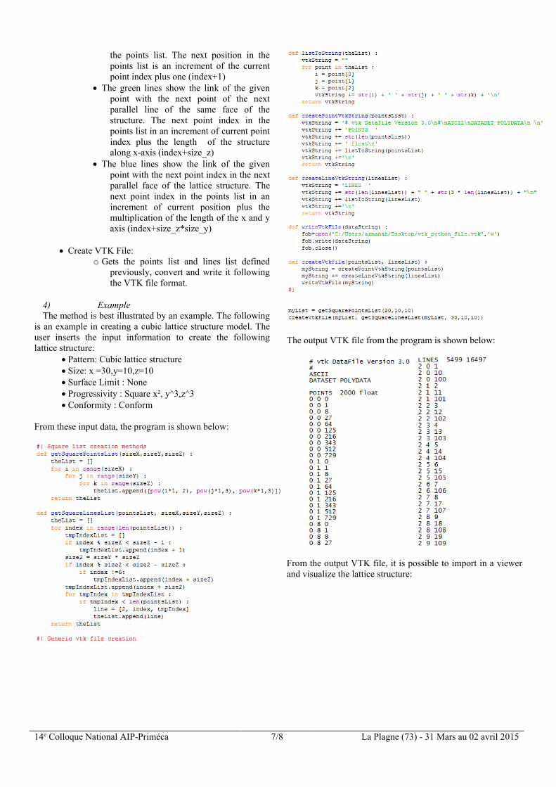
4) Example The method is best illustrated by an example. The following
is an example in creating a cubic lattice structure model. The user inserts the input information to create the following lattice structure:
Pattern: Cubic lattice structure Size: x =30,y=10,z=10 Surface Limit : None Progressivity : Square x², y^3,z^3 Conformity : Conform
From these input data, the program is shown below:
The output VTK file from the program is shown below:
From the output VTK file, it is possible to import in a viewer and visualize the lattice structure:
14e Colloque National AIP-Priméca 8/8 La Plagne (73) - 31 Mars au 02 avril 2015
Figure 21. LATTICE STRUCTURE CREATED
V. CONCLUSION AND PERSPECTIVES
Two advances are presented in this paper. First, the configurations of lattice structures parts for metallic additive manufacturing were presented. Second, a new proposed methodology to create lattice structure models.
New requirements in part designs for additive
manufacturing results in new needs for computer-aided-design software. Current CAD software are not tailored for these new requirements. This paper serves as a pre-study and basis for future works to create new CAD assistive tools to design for additive manufacturing and to create a new CAD file format for additive manufacturing.
VI. RÉFÉRENCES
[1] D. Brackett, I. Ashcroft, and R. Hague, “Topology optimization for additive manufacturing,” in Solid Freeform Fabrication Symposium, 2011, pp. 348–362.
[2] B. Vayre, F. Vignat, and F. Villeneuve, “Metallic additive manufacturing: state-of-the-art review and prospects,” Mech. Ind., vol. 13, no. 2, pp. 89–96, May 2012.
[3] G. Reinhart and S. Teufelhart, “Load-Adapted Design of Generative Manufactured Lattice Structures,” Phys. Procedia, vol. 12, pp. 385–392, Jan. 2011.
[4] D. Cooper, M. Stanford, K. Kibble, and G. Gibbons, “Additive manufacturing for product improvement at Red Bull Technology,” Mater. Des., vol. 41, pp. 226–230, Oct. 2012.
[5] A. G. Evans, J. W. Hutchinson, and N. a. Fleck, “The topological design of multifunctional cellular metals,” Prog. Mater. …, vol. 46, no. 3–4, pp. 309–327, 2001.
[6] M. P. Wolcott, “Cellular solids: Structure and properties,” Materials Science and Engineering: A, vol. 123. pp. 282–283, 1990.
[7] A. H. Azman, F. Vignat, and F. Villeneuve, “Evaluating Current CAD Tools Performances in the
Context of Design for Additive Manufacturing,” no. 44, pp. 1–7, 2014.
[8] M. Ashby, “Designing architectured materials,” Scr. Mater., vol. 68, no. 1, pp. 4–7, Jan. 2013.
[9] D. Rosen, “Computer-aided design for additive manufacturing of cellular structures,” Comput. Aided. Des. Appl., vol. 4, no. 5, pp. 585–594, 2007.
[10] M. Ashby, A. Evans, N. Fleck, L. Gibson, J. Hutchinson, H. Wadley, and F. Delale, “Metal Foams: A Design Guide,” Appl. Mech. Rev., vol. 54, no. 6, p. B105, Nov. 2001.
[11] M. F. Ashby, “The properties of foams and lattices.,” Philos. Trans. A. Math. Phys. Eng. Sci., vol. 364, no. 1838, pp. 15–30, Jan. 2006.
[12] L. Gibson, “Biomechanics of cellular solids,” J. Biomech., vol. 38, no. 3, pp. 377–399, Mar. 2005.