.... s, DESIGN CRITERIA FOR X-CRV HONEYCOMB PANELS - A PRELIMINARY STUDY Vincent Caccese University of Maine ES5 August 2, 1996 Irene Verinder Mechanical Design and Analysis Branch Structures and Mechanics Division Engineering Directorate https://ntrs.nasa.gov/search.jsp?R=19970025441 2019-02-01T15:45:52+00:00Z
Transcript
.... s,
DESIGN CRITERIA FOR X-CRV HONEYCOMB PANELS -A PRELIMINARY STUDY
Vincent Caccese
University of MaineES5
August 2, 1996
Irene Verinder
Mechanical Design and Analysis BranchStructures and Mechanics Division
University of MaineDept. of Mechanical Engineering
Engineering
Structures and Mechanics
Mechanical Design and Analysis
Irene Verinder
August 2, 1996
NAG 9-867
7-1
ABSTRACT
The objective of this project is to perform the first step in developing struem.ml designcriteria for composite sandwich panels that are to be used in the aeroshell of the crew returnvehicle (X-CRV). The preliminary concept includes a simplified method for assessing theallowable strength in the laminate material. Ultimately, it is intended that the design criteriabe extended to address the global response of the vehicle. This task will require execution
of a test program as outlined in the recommendation section of this report.
The aeroshell of the X-CRV is comprised of composite sandwich panels consisting offiberite face sheets and a phenolic honeycomb core. The function of the crew return vehicleis to enable the safe return of injured or ill crewpersons from space station, the evacuationof crew in case of emergency or the return of crew if an orbiter is not available. Asignificant objective of the X-CRV project is to demonstrate that this vehicle can bedesigned, built and operated at lower cost and at a significantly faster development time.Development time can be reduced by driving out issues in both structural design andmanufacturing concurrently. This means that structural design and analysis progresses in
conjunction with manufacturing and testing.
Preliminary tests results on laminate coupons are presented in the report. Based on theseresults a method for detection material failure in the material is presented. In the long term,
extrapolation of coupon data to large scale structures may be inadequate. Test coupons usedto develop failure criteria at the material scale are typically small when compared to theoverall structure. Their inherent small size indicates that the material failure criteria can be
used to predict localized failure of the structure, however, it can not be used to predictfailure for all failure modes. Some failure modes occur only when the structure or one of itssub-components are studied as a whole. Conversely, localized failure may not indicatefailure of the slructure as a whole and the amount of reserve capacity, if any, should beassessed.
To develop a complete design criteria experimental studies of the sandwich panel areneeded. Only then can a conservative and accurate design criteria be developed. Thiscriteria should include effects of flaws and defects, and environmental factors such as
temperature and moisture. Preliminary results presented in this report suggest that asimplified analysis can be used to predict the strength of a laminate. Testing forenvironmental effects have yet to be included in this work. The so called "rogue flaw test"
appears to be a promising method for assessing the effect of a defect in a laminate. Thismethod fits in quite well with the philosophy of achieving a damage tolerant design.
7-2
1.0 INTRODUCTION
The aerosheU of the crew return vehicle (X-CRV) vehicle is comprised of compositesandwich panels consisting of fiberite face sheets and a phenolic honeycomb core. A firststep in developing structural design criteria for these sandwich panels is the primary focusof this report. It includes a simplified method for assessing the allowable strength in thelaminate material. Ultimately it is intended that the design criteria be extended to addressthe global response of the vehicle. This task will require execution of a test program asoutlined in the recommendation section of this report.
The function of the crew return vehicle is to enable the safe return of injured or illerewpersons from space station, the evacuation of crew in case of emergency or the returnof crew if an orbiter is not available. The shape of the X-CRV is based upon theUSAF/Martin X-24A lifting body vehicle. A significant objective of the X-CRV project isto demonstrate that this vehicle can be designed, built and operated at lower cost and at asignificantly faster development time.
Substantial cost and weight savings can be achieved in aerospace vehicles through the useof composite materials. For example, the NASA/DoD advanced composites technologies
program has a projected goal of 30%-50% weight reduction and a 20%-25% cost savingswhen compared to a baseline aluminum wing and fuselage structure of a commercialvehicle in production (Smith et. al, 1995). The predicted savings are to be achieved by asynergism of innovative design and manufacturing techniques. Similar efficiencies are alsoanticipated for an aerospace vehicle such as the X-CRV. To this end, the experimentalversion of the crew return vehicle, the X-CRV, uses a composite sandwich as the structuralelement for the outer mold line (OML). One of the primary advantages in construction ofthis type over aluminum structures is that the part size can be relatively large. The costsavings accrue due to a reduction of labor required to fabricate and assemble these parts.Development time can be reduced by driving out issues in both structural design andmanufacturing concurrently. Furthermore, structural design and analysis progresses inconjunction with manufacturing and testing.
1.1 Development of Design Criteria
The focus of this report is to summarize a preliminary assessment of a simple andoperational criteria that can be used in the structural design of the X-CRV composite outeraerosheU. A structural design criteria can first be developed based upon classical mechanicsfailure criteria. These criteria are used to predict failure of the material locally. Preventingmaterial failure is a fast step in assuring the structural integrity.
Test coupons used to develop failure criteria at the material scale are typically small whencompared to the overall structure. This is especially true in a vehicle such as the X-CRV.
When these test coupons are fabricated they are effectively cut away from a larger sampleof the base material. Their inherent small size indicates that the material failure criteria can
be used to predict localized failure of the structure, however, it can not be used to predictfailure for all failure modes. Some failure modes occur only when the structure or one of its
subeomponents are studied as a whole. These failure modes and are not predicted bycoupons tests. Conversely, localized failure may not indicate failure of the structure as awhole and the amount of reserve capacity, if any, should be assessed.
In the long term, extrapolation of coupon data to large scale structures may be inadequate.Experimental verification of the failure criteria using components representative of the
7-3
globalstructural response is imperative. Testing of two-way panels is recommended foruse in the verification process. The validity and conservativeness of the design criteria canthen be assessed with confidence and results of panel tests can be correlated to finiteelement models of the structure.
In the end, the design criteria employed should be one that is reasonably accurate andoperationally simple. In choosing this criteria a realistic look at the design process isrequired. Ideally, a more complicated engineering solution is typically thought of as beingmore accurate. In an ideal situation the more complicated solution may be the engineerschoice because intuition tells us that it will yield a more optimum design at the expense of
some design time. Realistically, however, designs are subject to change caused byupdates to the desired service, cost concerns, and to correct for errors. Feeding thisinformation back into a more complicated analytical model may not be desirable. It willincrease the likelihood of errors and delay the design. Therefore, the choice of a
reasonably accurate, conservative, simpler criteria is better, especially for preliminarydesign.
1.2 Failure Criteria
The rationale behind mechanics failure criteria is that data from relatively simple tests can
be used to predict the failure of a material as it is subjected to more complex states of stressand strain. Failure criteria are based largely upon observation of test data and can be
thought of as operational rather than mechanistic. Failure criteria are empirical expressionsthat are related to the material failure process.
In polymer composites, better correlation between predictions and experiments have beenobserved when failure criteria is applied to the laminate rather than on a ply-by-ply basis(Norr et. al, 1983). In other words, a more accurate evaluation of the structural responsewill be determined from tests and analysis performed at the macroscopic scale. The
ultimate strength of a laminate can be predicted using the relevant strength data for a singleply. This, however, is a relatively complex problem. It is more appropriate to rely upontest data for laminate strength values. The basic material tests for the laminate consists of
standard coupon tests that are typically used to quantify material properties. These test aredone on a routine basis and data from these tests are input into the failure model. The sameholds true for evaluation of a composite sandwich and it will be more accurate to evaluatethis sandwich material at a scale large enough to represent the behavior of the strnctural
component.
There are numerous material failure criteria that have been developed in the pasL Rowlands
(1985) gives a comprehensive summary of a multitude of criteria. Two of the criteria usedfrequently in the analysis of composite materials, the maximum strain criteria (St. Venant)and the Tsai-Wu criteria, will be emphasized in this report.
For the most pan, failure criteria all agree in failure prediction when the material issubjected to simple states of stress such as uniaxial tension, uniaxial compression or pureshear. They differ when the effects of combined loading are to be predicted. Furthermore,failure criteria are to be used with caution because they will not predict all failure modes,
especially those that occur at the sub-component or component scale.
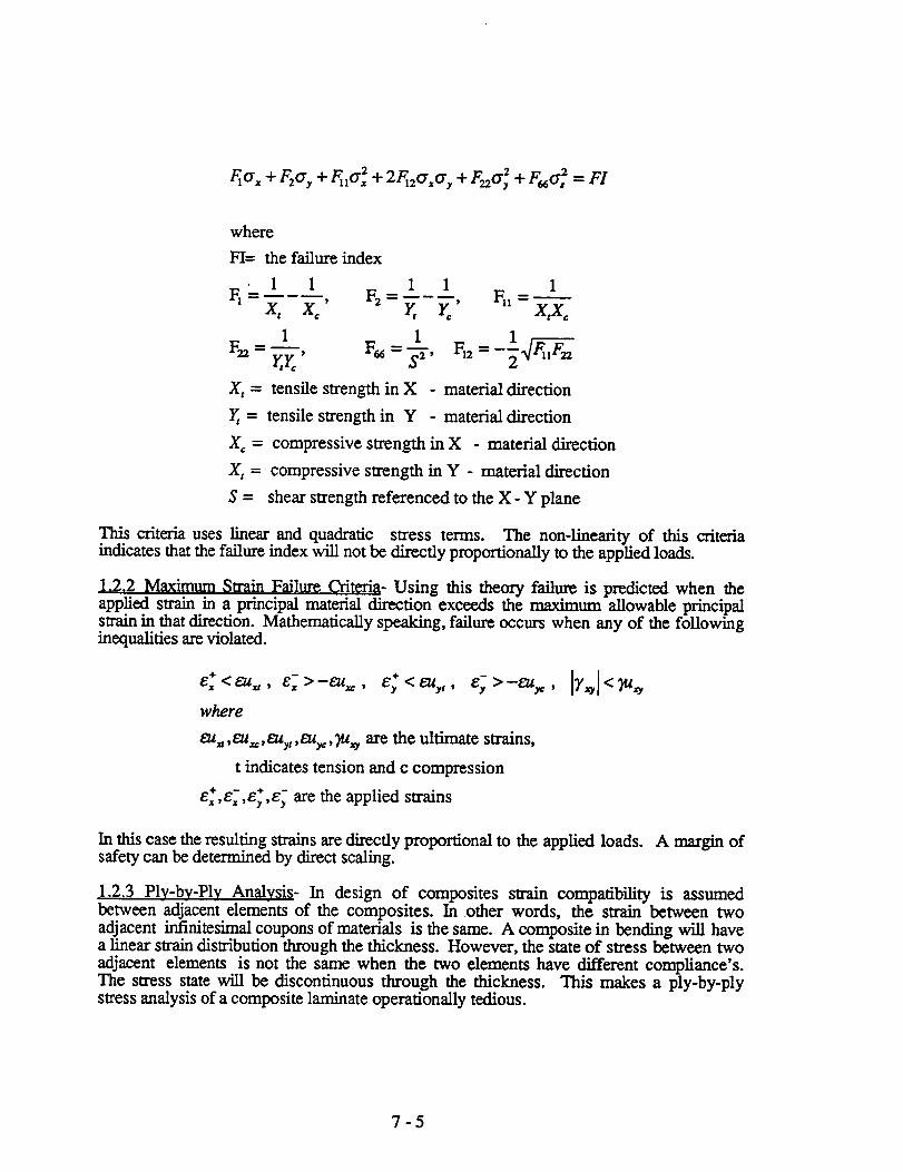
1.2.1 Tsai-Wu failure criteria - The Tsai-Wu failure criteria for orthortopic lamina can bewritten as follows:
This criteria uses linear and quadratic stress terms. The non-linearity of this criteriaindicates that the failure index will not be directly proportionally to the applied loads.
1.2.2 Maximum Slrain Failure Criteria- Using this theory failure is predicted when theapplied strain in a principal material direction exceeds the maximum allowable principalstrain in that direction. Mathematically speaking, failure occurs when any of the followinginequalities are violated.
4- 4-
e_ <EU.,, e_>-eu_., e_ <t_ty t, e_>-£u_,
where
_u=,eu_,t_uyt ,eu_:, Fz_ are the ultimate strains,
t indicates tension and c compression
e_,e_,e_,e_ are the applied strains
In this case the resulting strains are directly proportional to the applied loads. A margin ofsafety can be determined by direct scaling.
1.2.3 Ply-by-Ply Analysis- In design of composites strain compatibility is assumedbetween adjacent elements of the composites. In other words, the swain between twoadjacent infinitesimal coupons of materials is the same. A composite in bending will havea linear strain distribution through the thickness. However, the state of stress between two
adjacent elements is not the same when the two elements have different compliance's.The stress state will be discontinuous through the thickness. This makes a ply-by-plystress analysis of a composite laminate operationally tedious.
7-5
1.3 Damage Tolerant Criteria
In developing values for allowable material behavior a damage tolerant design is desiredwhere a component will maintain its structural integrity while a given defect is present.Damage tolerant design relies on accepting that damage will occur, on implementing asystem to detect damage, and on a design where adequate strength is maintained in thedamaged structure. Damage tolerance in composites is complex primarily due to the non-homogeneous nature of the material. Behavior of most carbon fiber reinforced compositesis nearly linear up to failure and the failures are sudden. In manufacturing of composites alarger number of defects may exist when compared to metallic structures.
Influence of an allowable defect can be incorporated into the design process. Defects in
composites can occur due to manufacturing preparation and production, machining,processing and of the assembly of the component. Some of these defects include voids,delaminations, disbonds, foreign object inclusions, resin starved or rich areas, incompleteresin cure, misaligned fiber orientation, fiber gaps, wrinkled layers, and poor surfaceconditions. In sandwich panels additional defects may include poor core splice, disbondsfrom facesheets, crushed core and core gaps. Assembly defects may result from scratches
gouges, incorrect drilling of holes and tool impact damage. The decision to repair or rejectthe component will be based upon the size and nature of the defect and its influence on thestructural performance. Accurate methods of evaluating the effect of the defect on thestructure and detection of the defect in the fhst place are required.
Undesirable structural response due to accumulation of damage under hysteresis loading,impact and fatigue should be mitigated. Damage due to impact depends upon the energylevel of the impact. High energy impacts will typically produce visible damage andprocedures can be set in action to mitigate the effects of this type of damage on thestructure. Low energy impact damage can be detrimental to the long-term life of thestructure and this damage is often difficult to detect. In composites damage is expected tooccur at quite low impact energy levels. This is especially true for sandwich panels.Thickening of the facesheets will help to lessen damage. Impact from an object such as a
toolbox dropped from 1 foot may produce significant damage in the composite structure.
Tension fatigue is not normally a problem in composites. Tests have shown that forspecimens with holes tension fatigue life is not a major concern. Specimens loaded to 90%of their ultimate tensile strength have achieved fatigue life of over 1 million cycles (Hoskinand Baker, 1986). On the other hand, compression specimens have shown a reducedfatigue life similar to that of metals. One million cycles was not achieved unless thecompressive stress was limited to less than 40 percent of the ultimate strength.
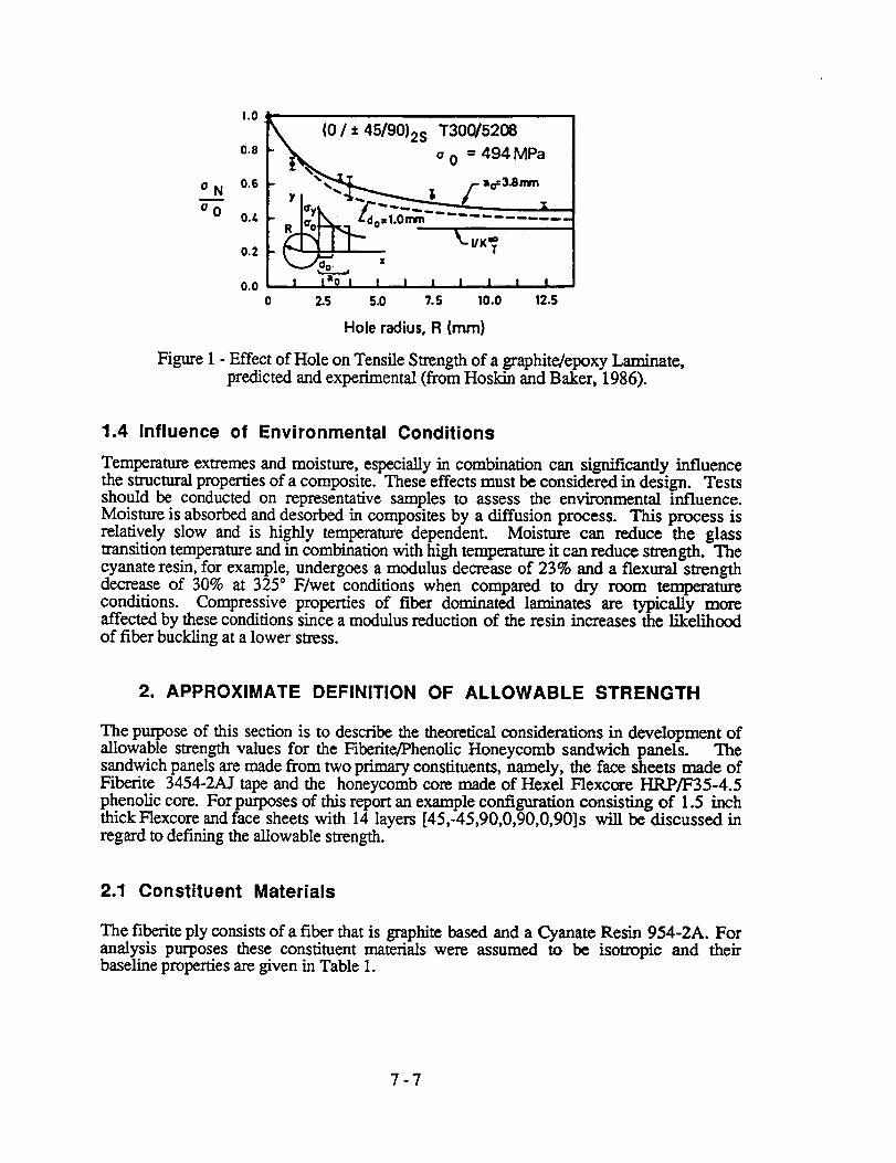
Damage tolerant design takes into account the type and size of defect that may be present inthe structure. Once the size and nature of the allowable defect is established, its effect on
the structure can be accounted for in the design process. Figure 1 shows the effect of sucha hole on the failure strength. In this case a 0.25 inch hole will reduce the failure strengthto 60% of its unflawed value. A crack of a 0.25 inch length will have a similar effect on
the tensile strength of the material.
One method for reducing the design allowables in composites design is the rogue flaw test.In this test a 1/4 inch diameter hole (flaw) is incorporated into a 1 inch wide tensile
specimen. In doing so, stress concentrations will occur around the flaw and the ultimatestrength and strain will be reduced by a substantial amount. This results in allowables thatcan be used at the material scale. Other damage tolerant criteria can be developed following
a similar philosophy.
7-6
o N
o 0
1.0
0.8
0.6
0./.
0.2
0.0
._(0 / + 45/90)2S T300/5208
o o = 494 MPa
_'_ /- ao=3.Bmm
I°'yk . f. -."Z" .....R ' -: .........
K._._o__.., xI la9 I I I I I J : I
2.5 5.0 ?.5 10.0 12.5
Hole radius, R (mm)
Figure 1 - Effect of Hole on Tensile Strength of a graphite/epoxy Laminate,predicted and experimental (from Hoskin and Baker, 1986).
1.4 Influence of Environmental Conditions
Temperature extremes and moisture, especially in combination can significantly influencethe structural properties of a composite. These effects must be considered in design. Testsshould be conducted on representative samples to assess the environmental influence.Moisture is absorbed and desorbed in composites by a diffusion process. This process isrelatively slow and is highly temperature dependent. Moisture can reduce the glasstransition temperature and in combination with high temperature it can reduce strength. Thecyanate resin, for example, undergoes a modulus decrease of 23% and a flextwal strengthdecrease of 30% at 325* F/wet conditions when compared to dry room temperatureconditions. Compressive properties of fiber dominated laminates are typicalty moreaffected by these conditions since a modulus reduction of the resin increases the likelihoodof fiber buckling at a lower stress.
2. APPROXIMATE DEFINITION OF ALLOWABLE STRENGTH
The purpose of this section is to describe the theoretical considerations in development ofallowable strength values for the Fiberite/Phenolic Honeycomb sandwich panels. Thesandwich panels are made from two primary constituents, namely, the face sheets made ofFiberite 3454-2AJ tape and the honeycomb core made of Hexel Flexcore HRP/F35-4.5phenolic core. For purposes of this report an example configuration consisting of 1.5 inchthick Flexcore and face sheets with 14 layers [45,-45,90,0,90,0,90]s will be discussed inregard to defining the allowable strength.
2.1 Constituent Materials
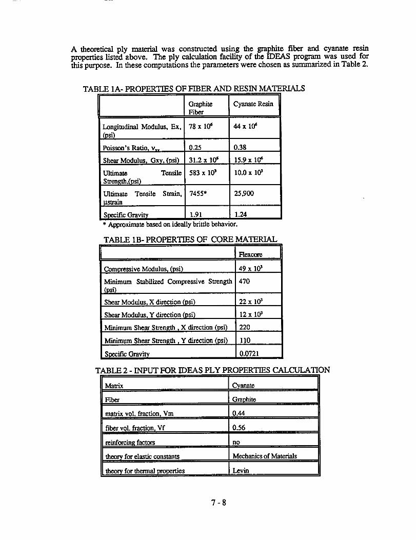
The fiberite ply consists of a fiber that is graphite based and a Cyanate Resin 954-2A. Foranalysis purposes these constituent materials were assumed to be isotropic and theirbaseline properties are given in Table 1.
7-7
A theoretical ply material was constructed using the graphite fiber and cyanate resinproperties listed above. The ply calculation facility of the IDEAS program was used forthis purpose. In these computations the parameters were chosen as summarized in Table 2.
TABLE 1A- PROPERTIES OF FIBER AND RESIN MATERIALS
Graphite Cyanate ResinFiber
Longitudinal Modulus, Ex. 78 x 10_ 44 x 10_
(psi)
0.25 0.38Poisson's Ratio) v_v
Shear Modulus) Gxy) (psi)
Ultimate Tensile
Strength,(psi)
Ultimate Tensile Strain,
_train
31.2 x 10⁶ 15.9 x 10⁶
583 x 103 10.0 x 10³
7455* 25,900
Specific Gravi W 1.91 1.24
* Approximate based on ideally brittle behavior.
TABLE 1B- PROPERTIES OF CORE MATERIAL
Compressive Modulus r (psi)
Minimum Stabilized Compressive Strength
(psi)
Shear Modulus, X direction (psi)
Shear Modulus, Y direction (psi)
Minimum Shear Strenl_th r X direction (psi)
Minimum Shear Strength, Y direction (psi)
Spocific Gravity
470
22x 103
12 x 103
220
110
0.0"/21
TABLE 2 -INPUT FOR IDEAS PLY PROPERTIES CALCULATION
Ma_ix Cyanate
Fiber Graphite
matrix vol. fraction, Vm 0.44
fiber vol. fraction, Vf 0.56
reinforcing factors no
theory for elastic constants Mechanics of Materials
theory for thermal properties Levin
7-8
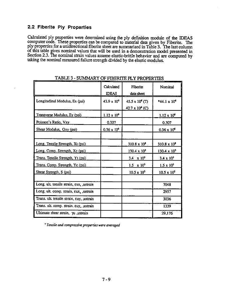
2.2 Fiberite Ply Properties
Calculated ply properties were determined using the ply defia'tition module of the IDEAScomputer code. These properties can be compared to material data given by Fiberite. Theply properties for a unidirectional fiberite sheet are summarized in Table 3. The last column
of this table gives nominal values that will be used in a demonstration model presented inSection 2.3. The nominal strain values assume elastic-brittle behavior and are computed bytaking the nominal measured failure strength divided by the elastic modulus.
TABLE 3 - SUMMARY OF FIBER1TE PLY PROPERTIES
Calculated
IDEAS
Longitudinal Modulus, Ex (psi) 43.9 x 10⁶
Transverse Modulus, Ey (psi) 1.12 x 10⁶
Poisson's Ratio, Vxy 0.307
Shear Modulus, Gxy (psi) 0.36 x I(Ys
Long. Tensile Strens_,h, Xt (psi)
Long. Comp. Strength r Xe (psi)
Trans. Tensile Strength, Yt (psi)
Trans. Comp. Strength r Yc (psi)
Shear Stren_h, S (psi)
Long. ult. tensile strain, eux_ ,ustrain
Long. ult. comp. strain, euxo ,uslrain
Trans. ulL tensile strain, euyt ,ustrain
Trans. ulL eomp. strain, euy, ,ustrain
Ultimate shear strain, "yu,ustrain
° Tensile and compressive properties were averaged
Fiberite
data sheet
310.8 x l0s
130.4 x los
3.4 xlos
1.5 xlos
10.5 x los
Nominal
• 44.1 x 10⁶
1.12 x 10⁶
0.307
0.36 x 10⁶
310.8 x los
130.4 x los
3.4 x 10s
1.5 x los
10.5 x los
7048
2957
3036
1339
29,176
7-9
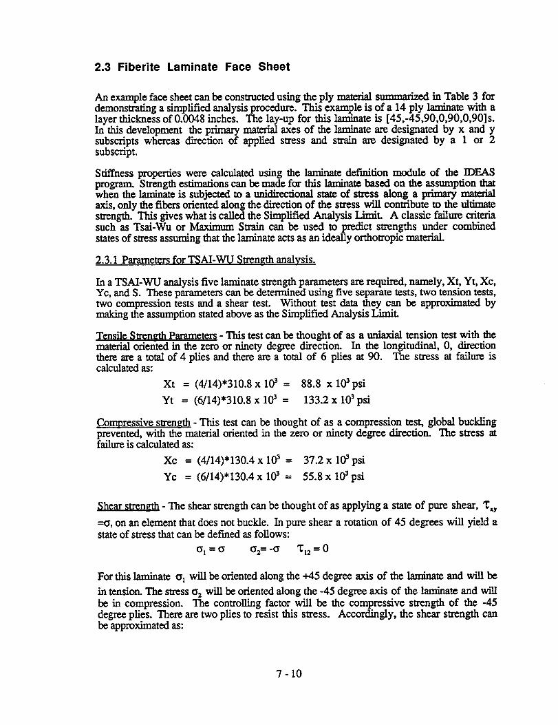
2.3 Fiberite Laminate Face Sheet
An example face sheet can be constructed using the ply material summarized in Table 3 fordemonstrating a simplified analysis procedure. This example is of a 14 ply laminate with alayer thickness of 0.0048 inches. The lay-up for this laminate is [45,-45,90,0,90,0,90] s.In this development the primary material axes of the laminate are designated by x and ysubscripts whereas direction of applied stress and strain are designated by a 1 or 2subscript.
Stiffness properties were calculated using the laminate definition module of the IDEASprogram. Strength estimations can be made for this laminate based on the assumption thatwhen the laminate is subjected to a tmidirectional state of stress along a primary materialaxis, only the fibers oriented along the direction of the stress will contribute to the ultimatestrength. This gives what is called the Simplified Analysis l.lm_t. A classic failure criteriasuch as Tsai-Wu or Maximum Strain can be used to predict strengths under combinedstates of stress assuming that the laminate acts as an ideally orthotropic material.
2.3.1 Parameters for TSAI-WU Strength analysis.
In a TSAI-WU analysis five laminate strength parameters are required, namely, Xt, Yt, Xc,Yc, and S. These parameters can be determined using five separate tests, two tension tests,two compression tests and a shear test. Without test data they can be approximated bymaking the assumption stated above as the Simplified Analysis Limit.
Tensile Strength Parameter_ - This test can be thought of as a uniaxial tension test with thematerial oriented in the zero or ninety degree direction. In the longitudinal, 0, directionthere are a total of 4 plies and there are a total of 6 plies at 90. The stress at failure iscalculated as:
Xt = (4/14)'310.8 x 103 -- 88.8 x 10³psi
Yt = (6/14)'310.8 x 103 = 133.2 x 10³ psi
Compressive strength - This test can be thought of as a compression test, global bucklingprevented, with the material oriented in the zero or ninety degree direction. The stress atfailure is calculated as:
Xc = (4/14)'130.4 x 103 = 37.2 x 10³ psi
Yc = (6/14)'130.4 x 103 - 55.8 x 10³ psi
Shear strength - The shear strength can be thought of as applying a state of pure shear, '171y
--_, on an element that does not buckle. In pure shear a rotation of 45 degrees will yield astate of stress that can be defined as follows:
(_1= ¢_ 02= "¢_ _12 = 0
For this laminate ol will be oriented along the +45 degree axis of the laminate and will be
in tension. The stress o 2 will be oriented along the -45 degree axis of the laminate and will
be in compression. The controlling factor will be the compressive strength of the -45degree plies. There are two plies to resist this stress. Accordingly, the shear strength canbe approximated as:
7 - 10
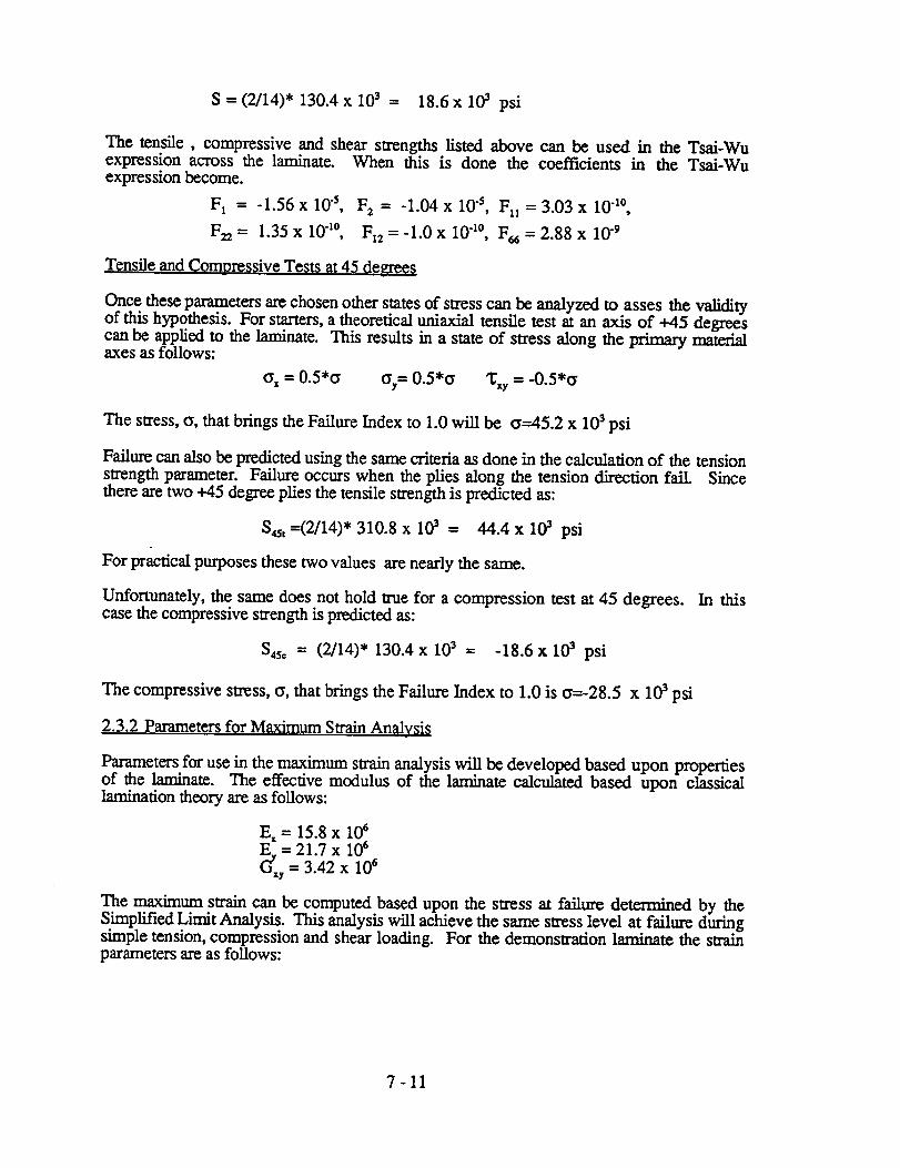
S - (2114)*130.4 × 103 = 18.6x 10³ psi
The tensile, compressive and shear strengths listed above can be used in the Tsai-Wuexpression across the laminate. When this is done the coefficients in the Tsai-Wuexpression become.
F 1 -- -1.56 x 10 "s, F 2 = -1.04 x 10 "s, F11 = 3.03 x 10 "1°,
F_, = 1.35 x 10 "l°, Fl2 = -1.0 x 10 "1°, F_ = 2.88 x 10 -9
Tensile and Compressive Tests at 45 de_'ees
Once these parameters are chosen other states of stress can be analyzed to asses the validityof this hypothesis. For starters, a theoretical uniaxial tensile test at an axis of +45 degreescan be applied to the laminate. This results in a state of stress along the primary materialaxes as follows:
¢_ = 0.5"¢_ ¢_y= 0.5*6 _y = -0.5*a
The stress, c, that brings the Failure Index to 1.0 will be o--45.2 x 10³ psi
Failure can also be predicted using the same criteria as done in the calculation of the tensionstrength parameter. Failure occurs when the plies along the tension direction fail. Sincethere are two +45 degree plies the tensile strength is predicted as:
S4s t =(2/14)* 310.8 x 103 - 44.4 x 10³ psi
For practical purposes these two values are nearly the same.
Unfortunately, the same does not hold true for a compression test at 45 degrees. In thiscase the compressive strength is predicted as:
S4sc = (2/14)* 130.4 x 103 = -18.6x 10z psi
The compressive stress, _, that brings the Failure Index to 1.0 is _=-28.5 x 10³ psi
2.3.2 Parameters for Maximum Strain Analvsi_
Parameters for use in the maximum strain analysis will be developed based upon propertiesof the laminate. The effective modulus of the laminate calculated based upon classicallamination theory are as follows:
E, = 15.8 x l0 sE, = 21.7 x 10⁶
G'_y = 3.42 x 10⁶
Th.e maximum strain can be computed based upon the stress at failure determined by theSmaplified Limit Analysis. This analysis will achieve the same stress level at failure duringsimple tension, compression and shear loading. For the demonstration laminate the strainparameters are as follows:
7-11
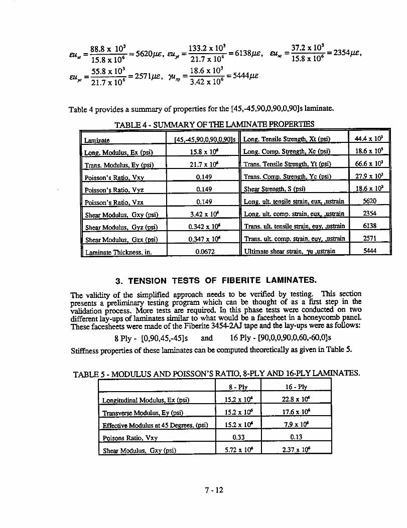
88.8 x 10³ 133.2 x 10³
eu._ = 15.8 x 106 = 5620//e, euy, = 21.7 x 106 = 6138/.te,
55.8 x 10³ 18.6 x 10³
eu_: 21.7x10⁶ 2571/.te, _ 3.42x 10⁴ 5444#e
37.2 x 10³
15.8 x 106= 2354/.te,
Table 4 provides a summary of properties for the [45,-45,90,0,90,0,90]s laminate.
TABLE 4 - SUMMARY OF THE LAMINATE PROPERTIES
T.qminate
i Long. Modulus, Ex (psi)
Trans. Modulus, Ey (psi)
Poisson's Ratio I Vx7
Poisson's Ratio, VTz
Poisson's Ratio r Vzx
Sh__._rModulus r Gxy (psi)
Shear Modulus, Gyz (psi)
Shear Modulus r Gzx (psi)
laminate Thickness, in.
[45r-45190r0T90,0,90] s
15.8 x 10_
21.7 x 10⁶
0.149
0.149
0.149
3.42 x 10⁶
0.342 x 10_
0.347 x 10⁶
0.0672
Long. Tensile Strength, Xt (psi)
Long. Comp. Strength, X¢ (psi)
Trans. Tensile Strengthr Yt (psi)
Trans. Comp. Stren_th_Yc (psi)
Shear Stren_da, S (psi)
Long. ult. tensile strain, curn rustrain
Long. ult. eomp. strain, eux_ ,uslrain
Trans. ult. tensile strainr euTr,ustrain
Trans. ult. comp. strain, euy= rustrain
Ultimate shear strain, _ rustrain
44.4 x l&
18.6 x 10³
66.6x 10³
27.9 x 10a
18.6 x 10³
5620
2354
6138
2571
5444
3. TENSION TESTS OF FIBERITE LAMINATES.
The validity of the simplified approach needs to be verified by testing. This section
presents a preliminary testing program which can be thought of as a first step in thevalidation process. More tests are required, h this phase tests were conducted on twodifferent lay-ups of laminates similar to what would be a faeesheet in a honeycomb panel.These facesheets were made of the Fiberite 3454-ZAJ tape and the lay-ups were as follows:
8 Ply - [0,90,45,-45]s and 16 Ply - [90,0,0,90,0,60,-60,0]s
Stiffness properties of these laminates can be computed theoretically as given in Table 5.
TABLE 5 - MODULUS AND POISSON'S RATIO, 8-PLY AND 16-PLY L,AMINATES.
Longitudinal Modulus, Ex (psi)
Transverse Modulus, Ey (psi)
Effective Modulus at 45 Degrees, (psi)
Poisons Ratio, Vxy
;hear Modulus, Gxy (psi)
8 - Ply
15.2 x 10⁶
16- Ply
22.8 x 10e
15.2 x 10⁶ 17.6 x 10s
15.2 x 10e 7.9 x 10e
0.33 0.13
5.72 x 10_ 2.37 x 10⁶
7 - 12
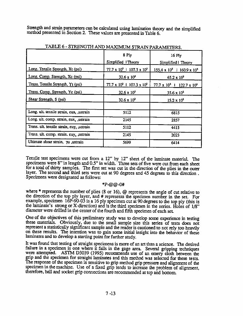
Strengthandstrain parameters can be cnlculated using lamination theory and the simplifiedmethod presented in Section 2. These values are presented in Table 6.
Tensile test specimens were cut from a 12" by 12" sheet of the laminate material. Thespecimens were 8" in length and 0.5" in width. Three sets of five were cut from each sheet
for a total of thirty samples. The ftrst set was cut in the direction of the plies in the outerlayer. The second and third sets were cut at 90 degrees and 45 degrees to this direction.Specimens were designated as follows:
*P-@@-0#
where * represents the number of plies (8 or 16), @ represents the angle of cut relative tothe direction of the top ply layer, and # represents the specimen number in the set. Forexample, specimen 16P-90-03 is a 16 ply specimen cut at 90 degrees to the top ply (this isthe laminate's strong or X-direction) and is the third specimen in the series. Holes of 1/8"diameter were drilled in the center of the fourth and fifth specimen of each set.
One of the objectives of this preliminary study was to develop some experience in testingthese materials. Obviously, due to the small sample size this series of tests does notrepresent a statistically significant sample and the reader is cautioned to not rely too heavilyon these results. The intention was to gain some initial insight into the behavior of theselaminates and to develop a starting point for further study.
It was found that testing of straight specimens is more of an art than a science. The desired
failure in a specimen is one where it fails in the gage area. Several gripping techniqueswere attempted. ASTM D3039 (1995) recommends use of an emery cloth between thegrip and the specimen for straight laminates and this method was selected for these tests.
The response of the specimen is sensitive to grip method grip pressure and alignment of thespecimen in the machine. Use of a fixed grip tends to increase the problem of alignment,therefore, ball and socket grip connections are recommended at top and bottom.
7 -13
Even with all of these precautions taken a majority of the specimens failed near to the griparea. Intuition tells us that this will most likely be the case. Failure in a specimen willinitiate at a flaw or due to a stress concentration in the specimen. The likelihood is smallthat a flaw will be more severe than the stress concentration near the grips.
Other recommended methods for gripping are use of tabs or fabrication of tapered
specimens. The tabs will help mitigate damage to the outer layers of the laminate and mayhelp to reduce the concentration of stress at the grips. The effectiveness of the tabs canonly be assessed by testing. Fabrication of tapered specimens is possible. Care should betaken to make the taper gentle enough so that stress concentrations am not excessive at the
taper. This would only move the problem fi:om one region to another. If a comprehensivelaminate testing program is to be undertaken an attempt at developing a tapered specimenshould be made. If this is not successful or practical it should be followed by studying the
feasibility of using tabs.
In testing of simulated flawed specimens with holes the gripping problems do not exist.These test results arc expected to be more consistent, and they were. Failure will virtually
always occur through the flawed region.
3.1 Test Results
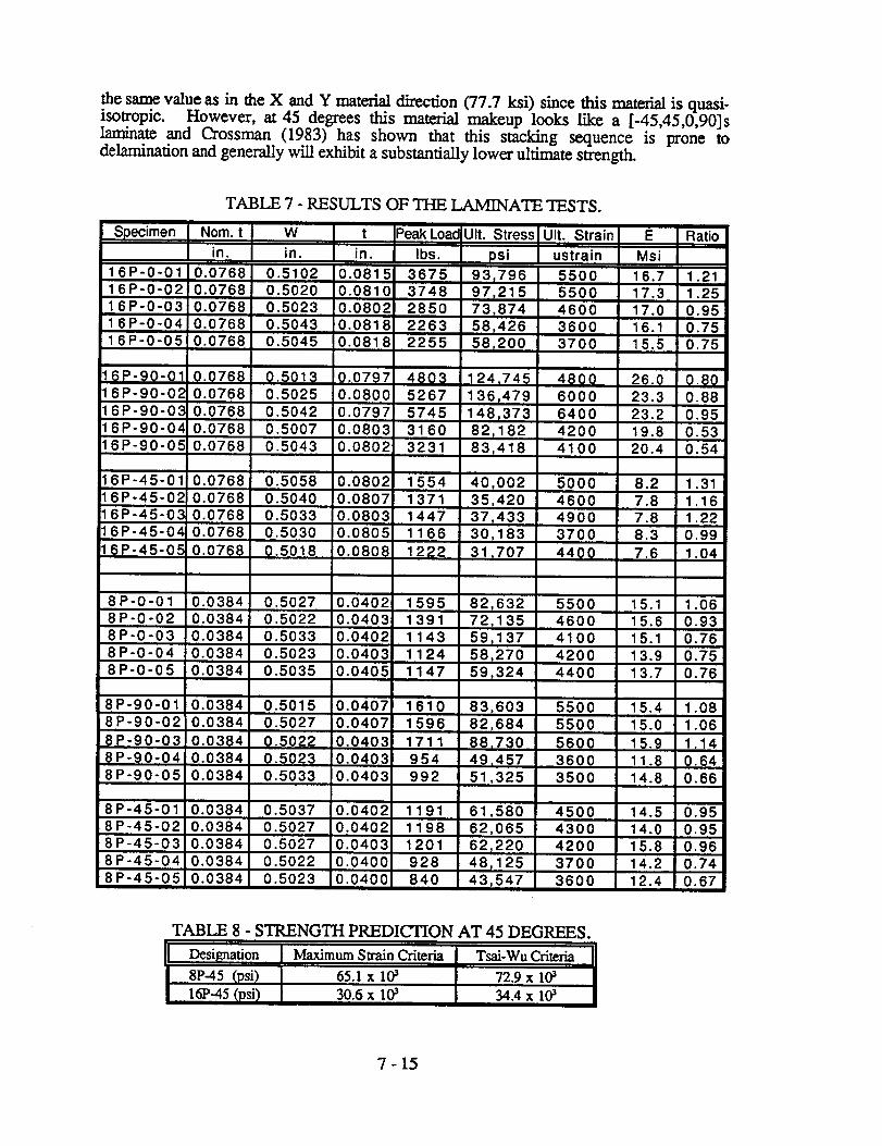
Results of the Fiberite laminate tests are summarized in Table 7, including the results of
both the straight specimens and the specimen with holes. The computations of modulus ofelasticity, E, and ultimate stress were based upon the nominal thickness. The last column
of this table provides a ratio of the strength, of the laminate to the strength determined by thesimplified method. For the off axis specanens cut at 45 degrees (8P-45 and 16P--45) theratio was based upon the limiting value of stress determined by the maximum strain criteriausing the parameters presented in Table 6.
Referring to the predicted modulus of elasticity presented in Table 5 and the experimentallydetermined modulus given in Table 7 it can be seen that this parameter can be predictedwith good accuracy using classic lamination theory. The average percent difference in thisprediction is -0.3% for the 8-Ply laminate, -3% for 16P-0, 6% for 16P-90 and -0.2% for16P-45.
In the 16-ply laminate tested on its strong axis (16P-90, Figure 3) one-half of the plies inthis case are oriented in the strong direction. The cross plies being at 60 degrees indicatesthat a relatively small amount of load sharing will be contributed by these plies. Also, thiscauses the simplified analysis limit to be relatively close to the lamination theory limit.Difficulties were observed in achieving the strength indicated by the simplified analysislimit as none of the three tests achieved this limit. In the other direction (16P-0, Figure 4)
the simplified analysis limit was achieved in two of the three tests and the lower strength inthe third tests was due to problems at the grips. In this case substantial load sharing occurs
by the cross plies which are located at an angle of thirty degrees. The 8-ply material(Figures 5-6) is a quasi-isotropic material and one would expect the same behavior in eitherdirection. In this lay-up significant load sharing exists due to the 45 degree plies. Four ofthe six tests achieved the simplified analysis limit.
In the off-axis tests at 45 degrees (8P-45 and 16P-45) the strength can be predicted using
the parameters presented in Table 6. Table 8 gives a summary of these predicted strengthsusing both the maximum strain and the Tsai-Wu criteria. The maximum strain criteria givesa more conservative prediction of the strength in this orientation. In the tests, the strength
of 16-ply material exceeded these predictions as indicated by a ratio greater than 1 in Table7. For the 8-ply material it may appear, at first glance, that both the maximum straincriteria and the Tsai-Wu criteria are overly conservative and that the strength should reach
7 -14
the same value as in the X and Y material direction (77.7 ksi) since this mate_ is quasi-
isotropic. However, at 45 degrees this material makeup looks like a [-45,45,0,90]s
laminate and Crossman (1983) has shown that this stacking sequence is prone to
delaminafion and generally will exhibit a substantially lower ultimate strength.
Designation J Maximum Strain Criteria J Tsai-Wu Criteria 11
8P-45 (psi) I 65.lx10a I 72.9xl& I16P-45 (lasi) 30.6 x 10a 34.4 x 10a
7 - 15
The rogue flaw tests of specimens with holes generally achieved 53%-70% (see Table 7)of the value predicted by simplified analysis. In the tests of 16P-45 this percentage wasgreater primarily due to an underpredicfion of the strength in this dh'ection by the maximumstrain criteria. Theoretically, the stress concentration factor for this hole is gratex than 3.The test results indicate a strength reduction factor less than 2 thereby indicating asignificant redistrubution of stress around the hole prior to failure.
4. RECOMMENDATIONS
The principal outcome of this preliminary study is to recommend an extensive testingprogram for the XCRV composite sandwich panels. These recommendations amsummarized as follows:
1. Perform an exhaustive search of the literature for experimental results which
may pertain to this material.
2. Perform a comprehensive test program to evaluate the structural response of theX-CRV sandwich panels at the sub-component and component scale. Correlatethese test results to finite element analysis. Include environmental effects,
defects and impact.
. Supplement the laminate coupon tests with additional tests of the laminate andsandwich core system. These tests will help to interpret the results of 2) above.They should be made of constituents used in the above study.
4. Develop a comprehensive design criteria based upon the results of the abovestudies.
5. CONCLUSIONS
A comprehensive design criteria can not be developed from material coupon tests alone.Structural response from tests at the sub-component and component level are required.This is especially true in composites and composite sandwich panels where theoreticalstrength analysis is complex. There are a multiplicity of failure modes that depend uponstructural geometry, load path and practical issues such as manufacturing techniques.
Experimental study of the sandwich panel as a whole is needed so that the global structuralresponse be understood. Only then can a conservative and accurate design criteria bedeveloped. The design procedure should be operationally simple and related to the methodsof the analytical tool that will be used in design, typically finite element analysis. Thiscriteria should include provisions for detecting any and all possible failure modes, bothlocal and global. Conversely, localized material failure may not indicate failure of thestructure or the component as a whole. Component testing will result in an assessment ofreserve capacity.
A rational approach is required for preliminary design which is often performed in theabsence of test results. Preliminary results presented in this report suggest that a simplifiedanalysis can be used to predict the strength of a laminate coupon. Care should be exercisedin choosing strength and strain parameters especially when there is not a significant numberof plies in the laminate at an angle of 45 degrees or less. Environmental effects have yet tobe included in this work. The so called "rogue flaw test" appears to be a promising method
for assessing the effect of a defect in a laminate. This method fits in quite well with thephilosophy of achieving a damage tolerant design.
7 -16
REFERENCES
Crossman, F.W., "Analysis of Delamination", in Failure Analysis and Mechanisms ofFailure of Fibrous Composite Structures , NASA Science and Technical InformationBranch, NASA Conference Publication No. 2278, pp. 191-240.
Finn, S. R., Dickson, J. N., Vause, R. F. D, Carbery, J., Bowman, L.M. , Dost, E. F.and Starnes Jr., J. H.,(1995), "Analysis of a Pathfinder Shell Subjected to InternalPressure and Mechanical Loads," Proceedings of the Fifth NASA/DoD AdvancedComposites Technology Conference, NASA Conference Publication No. 3294, V1, P1,pp. 33-73.
Grimes, G.C., Dusablon, E.G., Malone, R.L., and Buban, J.P., (1993) "Tape CompositeMaterial Allowables in Airframe Design/Analysis", Composites Engineering, PergamonPress, Great Britain, V.3, N 7-8, pp. 777-804.
Hoskin, B.C., and Baker, A. A., (1986) Composite Materials for Aircraft Structures,American Institute of Aeronautics and Astronautics, New York, N.Y.
McCarthy, J. E.,(1983) "Commercial Transport Aircraft Composite Structures", in F_ureAnalysis and Mechanisms of Failure of Fibrous Composite Structures, NASA Science andTechnical Information Branch, NASA Conference Publication No. 2278, pp. 7-66.
and Mechanisms of Failure of Fibrous Composite Structures , NASA Science andTechnical Information Branch, NASA Conference Publication No. 2278, pp. 1-5.
Rowlands, R.E. (1985), "Strength Failure Theories and Their Experimental Correlation",
Chapter 2, Failure Mechanics of Comoosites. Elsevier Science Publishers B.V.,Amsterdam, The Netherlands. pp. 71-125.
Sih, G.C., and Skudra, A.M.,ed. (1985), "Failure Mechanics of Composites", ElsevierScience Publishers B.V., Amsterdam, The Netherlands.
Smith, P. J., Ilcewicz, L. B., and Olson, J.T. (1995), "Advanced Technology CompositeFuselage," Proceedings of the Fifth NASA/DoD Advanced Composites TechnologyConference, Nasa Conference Publication No. 3294, V 1, P1, pp 1 -31.
"Standard Test Methods for Tensile Properties of Polymer Matrix Composite Materials",(1995) ASTM D3039/D3039M, American Society of Testing Materials, Philadelphia, Pa.
"Standard Test Methods for Shear Properties of Sandwich Core Materials", (1995) ASTMC273-94, American Society of Testing Materials, Philadelphia, Pa.
"Standard Test Methods for Flexural Properties Sandwich Construction", (1995) AS'I'MC393-94, American Society of Testing Materials, Philadelphia, Pa.