National Aeronautics and Space Administration www.nasa.gov 1 Design Curve Generation for 3D SiC Fiber Architecture J. Lang and J. DiCarlo NASA Glenn Research Center Cleveland, Ohio Research Supported by the NASA Fundamental Aeronautics Program Aero Sciences Project Presented at 38th Annual Conference on Composites, Materials, and Structures Cape Canaveral, Florida, January 28, 2014 https://ntrs.nasa.gov/search.jsp?R=20140016969 2020-03-14T19:04:28+00:00Z
Transcript
National Aeronautics and Space Administration
www.nasa.gov 1
Design Curve Generation for 3D SiC Fiber Architecture
J. Lang and J. DiCarlo
NASA Glenn Research Center Cleveland, Ohio
Research Supported by the
NASA Fundamental Aeronautics Program Aero Sciences Project
Presented at 38th Annual Conference
on Composites, Materials, and Structures Cape Canaveral, Florida, January 28, 2014
� In recent studies, NASA has shown that there are multiple performance advantages in using 3D architectures for advanced SiC/SiC composites. These advantages primarily arise from the use of thru-thickness fibers that provide composites with improved delamination resistance, improved impact resistance, and improved thru-thickness strength and thermal conductivity.
� It was also shown that if the matrix had reduced porosity, key structural and formation properties of advanced SiC/SiC composites are controlled and predictable from the fiber tow geometric characteristics and volume fractions within the fiber architecture. � This important observation initiated in-house studies aimed at developing user-friendly software tools that can be used for designing virtual 3D-woven architectures that will best meet the key fiber-controlled multi-directional property requirements of specific CMC components.
National Aeronautics and Space Administration
www.nasa.gov 3
� Describe recent progress in the development of NASA’s 3D design tool:
� Development of preform design curves for designing and validating virtual SiC/SiC composite panels containing down-selected 3D modified layer-to-layer architectures of high-stiffness high-performance Hi-Nicalon Type S SiC fibers
� Design curves allow an understanding and prediction of the effects of fiber geometry on key properties of 3D preforms, such as fiber fractions in three directions, preform height, and minimum fiber bend radius to avoid fiber fracture
� Fabrication of the down-selected preforms and validation of the design curve predictions for the key process and geometric properties of the preforms.
� Initial approach for extending the design tool to predict the key multi-directional property of Matrix Cracking Strength (MCS) for SiC/SiC reinforced by these architectures.
Presentation Outline
National Aeronautics and Space Administration
www.nasa.gov 4
Key Tow Shapes and Dimensions in 2D and 3D Woven Architectures
Assumption: Tows are completely conformable while retaining 60% fiber packing Tow Shape Rectangular
(also square) Elliptical
(also circle) Half
Lenticular Diamond
Tow Schematics
Typical Architectures
where Tow Shape will appear
3D orthogonal and angle interlock:
stuffers and weavers
2D fabric: stuffers
3D orthogonal and angle interlock: surface stuffers
3D angle interlock:
warp and fill stuffers
Tow Height (h) x Tow Width (w) for (n) bundled tows
(Total Tow Area = n Ao)
hw =1.0 (n Ao )
hw =1.3 (n Ao )
hw �1.4 (n Ao )
hw = 2.0 (n Ao )
National Aeronautics and Space Administration
www.nasa.gov 5
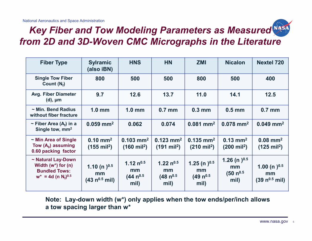
Key Fiber and Tow Modeling Parameters as Measured from 2D and 3D-Woven CMC Micrographs in the Literature
Fiber Type Sylramic (also iBN)
HNS HN ZMI Nicalon Nextel 720
Single Tow Fiber Count (Nf)
800 500 500 800 500 400
Avg. Fiber Diameter (d), μm
9.7 12.6 13.7 11.0 14.1 12.5
~ Min. Bend Radius without fiber fracture
1.0 mm 1.0 mm 0.7 mm 0.3 mm 0.5 mm 0.7 mm
~ Fiber Area (Af) in a Single tow, mm2
0.059 mm2 0.062 0.074 0.081 mm2
0.078 mm2 0.049 mm2
~ Min Area of Single Tow (A0) assuming 0.60 packing factor
Note: Lay-down width (w*) only applies when the tow ends/per/inch allows a tow spacing larger than w*
National Aeronautics and Space Administration
www.nasa.gov
NASA Computer-Based Visualization Tool for Basic 3D Architecture Types
Through Thick Angle Interlock w/o Warp Stuffers
Ply-to-Ply Angle Interlock, TEAM Inc recommendation
Through Thick Angle Interlock w/ Warp Stuffers
3D Orthogonal -1 float
Warp Weaver
Fill Stuffer Warp Stuffer
National Aeronautics and Space Administration
www.nasa.gov 7
3D Architecture Design Activities and Process Constraints
Objective: Generate design curves for the key process, geometric, and mechanical properties of 3D architectures for virtual composites based on the following constraints that are applicable to SiC/SiC CMC reinforced by high-performance high-stiffness SiC fibers: � Keep fibers as straight as possible in-plane for highest in-plane MCS and rupture strength �Avoid fiber fracture caused by bending and abrasion of the best stoichiometric SiC fibers: Warp weaver bend radius > fiber fracture radius �Maximize total fiber volume fraction for sufficient multi-directional reinforcement �Assure sufficient fiber content in the x, y, z directions to meet typical component multi-directional structural requirements. Key: high effective z fiber fraction for thru-thickness properties
National Aeronautics and Space Administration
www.nasa.gov
Current Down-selected 3D Architectures for SiC/SiC Composites
� Based on performance characteristics desired such as total volume content, panel height, tow float, tow bundle, directional fiber volume content, and ease of fabrication, design tool was used to down-select three types of 3D modified layer-to-layer architectures of high-stiffness high-performance Hi-Nicalon Type S SiC fibers. � Preforms of these architectures were fabricated by TEAM and will eventually be used to fabricate SiC/SiC panels for property evaluation. � Design tool predictions were compared to those measured on the final preforms.
Warp Weaver
Fill Stuffer Warp Stuffer
National Aeronautics and Space Administration
www.nasa.gov 9
Process Property Curves for Modified 3D Layer-to-Layer Angle Interlock
HNS Limit
10
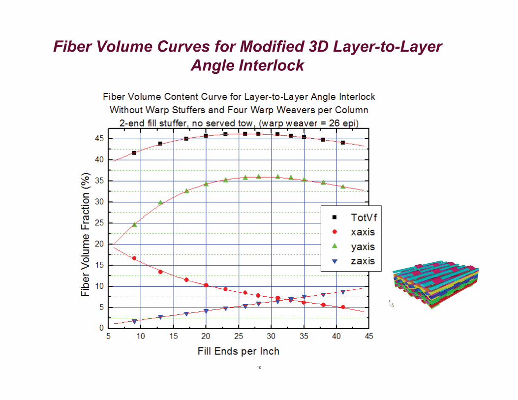
Fiber Volume Curves for Modified 3D Layer-to-Layer Angle Interlock
National Aeronautics and Space Administration
www.nasa.gov
Design Tool Prediction of T.E.A.M., Inc Preforms
National Aeronautics and Space Administration
www.nasa.gov 13
Design Tool* for Predicting and Optimizing Architecture Effects on Matrix Cracking Strength for Dense SiC/SiC
Key Architecture Factors Controlling Multi-Directional MCS: f0 = effective fiber volume fraction in test direction (needs to be maximized) h� (mm) = maximum height of tows perpendicular to test direction (needs to be minimized)
Thru-Thickness Cracking
Tow Height h
T
� + 48
� ~ residual stress on
matrix
* G. N. Morscher, J. A. DiCarlo, J. D. Kiser, and H. M. Yun, ‘‘Effects of Fiber Architecture on Matrix Cracking for Melt-Infiltrated SiC/SiC Composites,’’ Int. J. Appl. Ceram. Technol., 7 [3] 276–290 (2010).
Architecture recommendation by TEAM Inc. Modified layer-to-layer
National Aeronautics and Space Administration
www.nasa.gov 14
MCS Prediction for Modified 3D Layer-to-Layer Angle Interlock
National Aeronautics and Space Administration
www.nasa.gov
Summary and Future Directions
� The design tool provides design curves that allow a simple and quick way to examine multiple factors that can influence the processing and key properties of the preforms and their final SiC-reinforced ceramic composites without over obligating financial capital for the fabricating of materials.
� Tool predictions for process and fiber fraction properties have been validated for a HNS 3D preform.
� The virtualization aspect of the tool will be used to provide a quick generation of solid models with actual fiber paths for finite element evaluation to predict mechanical and thermal properties of proposed composites as well as mechanical displacement behavior due to creep and stress relaxation to study load sharing characteristic between constitutes for better performance.
� Tool predictions for the fiber controlled properties of the SiC/SiC CMC fabricated from the HNS preforms will be valuated and up-graded from the measurements on these CMC.


![Chapter 2 SiC Materials and Processing Technology€¦ · 34 2 SiC Materials and Processing Technology Table 2.1 Key electrical parameters of SiC [1] Property 4H-SiC 6H-SiC 3C-SiC](https://static.documents.pub/doc/80x56/5f4fd11797ddad63bf719816/chapter-2-sic-materials-and-processing-technology-34-2-sic-materials-and-processing.jpg)


