Page 1
DESIGN AND DEVELOPMENT OF HIGH BEAM REDUCTION
SYSTEM
Esuyawkal Melaku Temesgen
A Thesis Submitted to
The Department of Mechanical Systems and Vehicle Engineering
School of Mechanical, Chemical and Materials Engineering
Presented in Partial Fulfillment of the Requirement for the degree of Master of
Science in Automotive Engineering
Office of Graduate Studies
Adama Science and Technology University
July, 2021GC
Adama, Ethiopia
Page 2
DESIGN AND DEVELOPMENT OF HIGH BEAM REDUCTION
SYSTEM
Esuyawkal Melaku Temesgen
Advisor: Amana Wako (Ph.D)
A Thesis Submitted to
The Department of Mechanical Systems and Vehicle Engineering
School of Mechanical, Chemical and Materials Engineering
Presented in Partial Fulfillment of the Requirement for the degree of Master of
Science in Automotive Engineering
Office of Graduate Studies
Adama Science and Technology University
July, 2021GC
Adama, Ethiopia
Page 3
Page i of 97
DECLARATION
I hereby declare that this Master Thesis entitled “Design And Development Of High Beam
Reduction System” is my original work. That is, it has not been submitted for the award of
any academic degree, diploma or certificate in any other university. All sources of
materials that are used for this thesis have been duly acknowledged through citation.
_______________ _______________ _______________
Name of the student Signature Date
Page 4
Page ii of 97
RECOMMENDATION
I, the advisor of this thesis, hereby certify that I have read the revised version of the thesis
entitled “Design and Development of High Beam Reduction System” prepared under my
guidance by Esuyawkal Melaku submitted in partial fulfillment of the requirements for the
degree of Mater’s of Science in Automotive Engineering.
Therefore, I recommend the submission of revised version of the thesis to the department
following the applicable procedures.
_______________ _______________ _______________
Major Advisor Signature Date
Page 5
Page iii of 97
APPROVAL PAGE
I, the advisors of the thesis entitled “Design And Development Of High Beam Reduction
System” and developed by Esuyawkal Melaku, hereby certify that the
recommendation and suggestions made by the board of examiners are appropriately
incorporated into the final version of the thesis.
_____________________________ _____________________ ___________________
Advisor Signature Date
We, the undersigned, members of the Board of Examiners of the thesis by Esuyawkal
Melaku have read and evaluated the thesis entitled “Design and Development of High
Beam Reduction System” and examined the candidate during open defense. This is,
therefore, to certify that the thesis is accepted for partial fulfillment of the requirement of
the degree of Master of Science in Automotive Engineering.
_____________________________ _____________________ ___________________
Chairperson Signature Date
_____________________________ _____________________ ___________________
Internal Examiner Signature Date
_____________________________ _____________________ ___________________
External Examiner Signature Date
_____________________________ _____________________ ___________________
Head of the Department Signature Date
_____________________________ _____________________ ___________________
School Dean Signature Date
_____________________________ _____________________ ___________________
Post Graduate Dean Signature Date
Page 6
Page iv of 97
ACKNOWLEDGMENT
Foremost, I want to offer this endeavor to my Almighty God for the wisdom he spills up on
me, the strength, peace of my mind, and good health to finish this research.
I would like to express my special gratitude and thanks to my advisor Dr. Amana Wako for
imparting his knowledge and expertise through guidance and supervision in this study.
I would like to express my special gratitude and thanks to Ato Esayas Meshesh for
imparting his knowledge and expertise through guidance and supervision in this study.
I would like to express my eternal appreciation towards my parents and family for all their
unconditional supports and patience. Thank you for being ever so understanding and
supportive.
I would like to thank Anbessa City Bus Enterprise, especially, employees working in the
department of engineering their willingness to participate in the study. I would like to thank
my dear friends and colleagues.
Page 7
Page v of 97
TABLE OF CONTENTS
CONTENTS PAGE
DECLARATION ................................................................................................................... i
RECOMMENDATION ........................................................................................................ ii
APPROVAL PAGE ............................................................................................................. iii
ACKNOWLEDGMENT ...................................................................................................... iv
LIST OF TABLES ............................................................................................................. viii
LIST OF FIGURES ............................................................................................................. ix
ACRONOMY ...................................................................................................................... xi
CHAPTER ONE ................................................................................................................... 1
INTRODUCTION ................................................................................................................ 1
1.1. Background of the study ......................................................................... 1
1.2. Statement of the Problem ....................................................................... 4
1.3. Objectives ............................................................................................... 5
1.3.1. General Objective .................................................................................................... 5
1.3.2. Specific Objectives ................................................................................................ 5
1.4. Significance of the study ........................................................................ 5
1.5. Scope of the thesis work ......................................................................... 5
1.6. Limitation of the study ........................................................................... 5
CHAPTER TWO .................................................................................................................. 7
2.1. LITERATURE REVIEW ....................................................................... 7
2.1.1. Battery .................................................................................................................. 13
2.1.2. Light Dependent Resistor ..................................................................................... 13
2.1.3. Sensitivity of Light Dependent Resistor .............................................................. 14
2.1.4. Transistor BC547 ................................................................................................. 15
2.1.5. Light Emitting Diode ........................................................................................... 16
2.1.6. Diode (1N4001) ................................................................................................... 16
2.1.7. Variable Resistor .................................................................................................. 17
2.1.8. Buzzer .................................................................................................................. 17
2.1.9. Relay .................................................................................................................... 17
2.1.10. Automotive Headlight .......................................................................................... 18
2.1.11. Low Beam ............................................................................................................ 19
Page 8
Page vi of 97
2.1.12. High Beam ........................................................................................................... 20
2.1.13. Illuminance (lux) .................................................................................................. 21
2.1.14. Luminous Flux (Lm) ............................................................................................ 21
2.1.15. Luminous Intensity (Candela) or cd..................................................................... 22
2.1.16. Electrical Breadboard ........................................................................................... 22
2.2. Microcontroller.................................................................................... 22
2.2.1. Arduino Uno .......................................................................................................... 23
2.2.2. Arduino Uno Technical Specifications ................................................................ 26
2.2.3. Jumper Wire ......................................................................................................... 26
2.3. Research Gap ........................................................................................ 27
CHAPTER THREE............................................................................................................. 28
MATERIALS AND METHODS ........................................................................................ 28
3.1. Materials ............................................................................................... 28
3.1.1. Materials required for design development of high beam reduction ................... 28
3.1.2. Engine Isuzu 4HKI-TCC ..................................................................................... 28
3.1.3. Electrical System.................................................................................................. 29
3.2. Methods ........................................................................................................................ 29
3.3. Population and Sampling ............................................................................................. 30
3.3.1. Target population ................................................................................................... 30
3.3.2. Sample frame ......................................................................................................... 30
3.3.3. Sample Unit............................................................................................................ 31
3.3.4. Sampling Technique .............................................................................................. 31
3.3.5. Sample Size ............................................................................................................ 31
3.4. Sources of Data ............................................................................................................ 32
3.4.1. Method of data collection ...................................................................................... 32
3.5. Data Analysis and Interpretation.................................................................................. 32
3.6. Arduino Uno Microcontroller Programming ............................................................... 33
3.6.1. Controlling Statements ........................................................................................... 34
3.6.2. Analog and Digital Functions ................................................................................ 36
3.6.3. Flowchart of the program ....................................................................................... 36
3.6.4. Simulation .............................................................................................................. 37
3.6.5. Prototype Construction .......................................................................................... 37
3.6.6. Process Description ................................................................................................ 37
Page 9
Page vii of 97
3.6.7. Proteus Software .................................................................................................... 38
3.6.8. Procedure and working flow of the thesis .............................................................. 38
CHAPTER FOUR ............................................................................................................... 39
RESULT AND DISCUSSION ........................................................................................... 39
4.1. Demographic Characteristics of Respondents ................................................ 39
4.2. Age of driver vs Type of vehicle their drive .................................................. 40
4.3. Driving Time at Night ............................................................................... 40
4.4. Difficult to see object on the road due to high beam light ................................ 41
4.5. Solution of Driver ..................................................................................... 42
4.6. Problem High Beam Glare.......................................................................... 43
4.7. Type of Accident Happen at Night Due to High Beam Glare ........................... 44
4.8. Isuzu NPR 75-190 Headlight System ........................................................... 45
4.9. The intensity of Headlight of Vehicle ........................................................... 46
4.10. Distance and Illuminance Intensity Relationship ............................................ 47
4.11. Vehicle Light Lumen vs. LDR Resistance ..................................................... 48
4.12. Vehicle Light Lumen vs. LDR Resistance value ............................................ 49
4.13. Light Dependent Resistor and Voltage Output Analysis .................................. 50
4.14. Voltage Divider Network ........................................................................... 51
4.15. Summary ................................................................................................. 56
CHAPTER FIVE................................................................................................................. 57
CONCLUSION, AND RECOMMENDATION ................................................................. 57
5.1. Conclusion ............................................................................................... 57
5.2. Recommendation ...................................................................................... 57
REFERENCE ......................................................................................................................... i
Appendix II; Timestamp (ms) VS Illuminance (Lux) ......................................................... vi
Appendix III; Arduino sketch for High beam to low beam ............................................... xix
Appendix IV; Circuit Diagram of Newly Developed System .......................................... xxv
Page 10
Page viii of 97
LIST OF TABLES
TABLE PAGE
Table 2. 1.Electrical Characteristics of LDR ........................................................................ 15
Table 2. 2. Arduino Uno microcontroller datasheet ............................................................. 26
Table 3. 1. List of material for the system…………………………………………………28
Table 3. 2. Vehicle specification .......................................................................................... 29
Table 3. 3. Sample size summary ......................................................................................... 32
Table 3. 4. Operator and their description ............................................................................ 34
Table 3. 5. Data types and their size and range .................................................................... 34
Table 4. 1. Demographic Characteristic of Respondent…………………………………...39
Table 4. 2. Difficulty to see the object on the road due to beam light.................................. 41
Table 4. 3. A solution has taken by drivers .......................................................................... 42
Table 4. 4. Problems happen by high beam glare ................................................................. 43
Table 4. 5. Type of accident happen during drive at night due to high beam glare ............. 44
Page 11
Page ix of 97
LIST OF FIGURES
FIGURE PAGE
Figure 2. 1. Different visions of eye ..................................................................................... 10
Figure 2. 2. Accident report of Asia due to Troxler effect in 2013 ...................................... 11
Figure 2. 3. Illumination (Lux) vs resistance in Ω ............................................................... 14
Figure 2. 4. Resistance K Ω vs Illuminance Intensity (Lux) ................................................ 15
Figure 2. 5. Filament for the low beam is fitted with a shell ................................................ 18
Figure 2. 6. Different vehicle light lumens and lamps have a throw different distance (m) 19
Figure 2. 7. Low beam of Car headlight ............................................................................... 20
Figure 2. 8. High Beam of Car headlight ............................................................................. 21
Figure 2. 9. Electrical Breadboard ........................................................................................ 22
Figure 2. 10. Arduino Uno ATmega328P ............................................................................ 24
Figure 2. 11. Jump wire ........................................................................................................ 27
Figure 3. 1. Flowchart of the program……………………………………………………..37
Figure 3. 2. Block diagram of high beam reduction system………………………………. 38
Figure 4. 1. Age of driver vs Type of vehicle their drive………………………………….40
Figure 4. 2. Driving time of driver at night……………………………………………….. 41
Figure 4. 3. A solution has taken by the driver……………………………………………. 43
Figure 4. 4. Existing Isuzu NPR 75-190 headlight wire diagram…………………………. 45
Figure 4. 5.Timestamp (ms) Vs Illuminance (Lux) ……………………………………… 46
Figure 4. 6. Average data for Low Beam Headlight……………………………………… 47
Figure 4. 7. Illuminance (Lux) Vs Distance (m) ………………………………………… 47
Figure 4. 8. When the vehicle at a far distance……………………………………………. 48
Figure 4. 9. When vehicle approach………………………………………………………. 48
Figure 4. 10. Vehicle Light Lumen vs. LDR Resistance value…………………………… 49
Figure 4. 11. Circuits of LDR and variable Resistor……………………………………… 50
Figure 4. 12. LDR resistor (Ω) Vs Voltage output (v) …………………………………… 51
Page 12
Page x of 97
Figure 4. 13. Newly Designed High Beam reduction system circuit diagram……………. 52
Figure 4. 14. The material used for the System…………………………………………… 53
Figure 4. 15. System functioning light……………………………………………………. 54
Figure 4. 16. Parking light switch ON ……………………………………………………. 54
Figure 4. 17. Low beam light switch ON ………………………………………………… 55
Figure 4. 18. High beam light switch ON with low beam ………………………………... 55
Figure 4. 19. Warning light switch ON with low beam…………………………………… 56
Page 13
Page xi of 97
ACRONOMY
AATA Addis Ababa Transport Authority
AATM Addis Ababa Traffic Management
AC Alternative Current
DC Direct Current
EBG Equatorial Business Group
ECU Electronic Control Unit
EEPROM Electrically Erasable Programmable Read-Only Memory
FTA
FMVSS
Federal Transport Authority
Federal Motor Vehicle Safety Standards
I/O Input Out Put
ICSP In circuit Serial Programming
IDE Integrated Development Environment
LDR Light Dependent Resistor
LED Light Emitting Diode
MISO
MHz
Master In Slave Out
Mega Hertz
MOSI Master-Out, Slave-In
NHTSA National Highway Traffic Safety Administration
PWM Pulse Width Modulation
RTAs Road Traffic Accidents
SCL Serial Clock Line
SD Secure Digital
SPSS Statistical Package For The Social Sciences
SRAM Static Random Access Memory
TD Derba Transport
TT Tana Transport
USB Universal Serial Bus
VSM Virtual System Modeling
Page 14
Page xii of 97
ABSTRACT
The vehicle lighting system is the most important vehicle electrical system. The headlight
helps to increase the visibility of the driver at night time and to enhance the driver to see an
object on the road and roadside clearly at a long distance. While driving at night has a
great problem on an opposite vehicle due to high beam headlights of vehicles pose a great
danger during night driving. Driver’s experiences a sudden glare for a short time. This is
caused due to the high intense headlight beam from the other vehicle coming towards him
from the opposite direction. This glare causes temporary blindness to a person resulting in
road accidents during the night like vehicle rollover, vehicle to vehicle collision, and, a
vehicle collided with the un-movable object and, loss of its lane. To mitigate this problem
by design and develop a high beam reduction system. This system automatically reduces
high beam to low beam by sensing the approaching opposite vehicle light intensity to LDR
sensor-based mechanism is utilized to develop the system. The system used the Arduino
UNO board and application-specific sensors LDR. The light sensor takes the “lux” reading
of the headlight rays from the opposing vehicle and checks for a threshold value assigned
in the coding. Based on the threshold value the beam switches from high to low state and
vice-versa when both the vehicles pass by each other. The LDR senses the light of the
opposite vehicle and warns the driver using a buzzer. If the driver does not take action the
system will reduce the high beam to low beam. Also when the opposite coming vehicle with
high beam and the newly designed system give different warning colored light which is
when the light intensity of opposite coming vehicle with high beam. This research has been
conducted by field observation on a vehicle that is driving at nighttime and ask the driver
to know the severity of the problem and analyzing the existing head lighting system. Design
and developing a high beam reduction system, simulate by proteus professional 8.7
software and assemble the part, and show the prototype.
Keywords: - Arduino UNO Microcontroller, Glaring effect, LDR, Temporary Blindness
Page 15
Page 1 of 97
CHAPTER ONE
INTRODUCTION
1.1. Background of the study
Light is electromagnetic radiation within a certain portion of the electromagnetic
spectrum. The word light refers to visible light, which is visible to the human eye and it
is responsible for the sense of sight. Visible light has a wavelength in the range of 400-
700 nanometers (nm), between the infrared (with longer wavelengths) and the ultraviolet
(with shorter wavelength). Light can be produced by nature or by humans. Artificial light
is typically produced by lighting systems that transform electrical energy into light.
The most fundamental reason for using light at night is to enable people walking
outdoors after dark to see obstacles on their path ahead and thereby avoid colliding with
them or tripping over them (Boyce, 2019). Because at night time it’s difficult to do their
activity properly. At nighttime human being,'s eye vision minimizes the ability to
identify objects easily or the human eye completely does not see objects during
nighttime.
Driving in the dark is very different from driving during daylight hours. Night driving is
difficult for many drivers. The human eye’s field of vision is much smaller without the
help of natural light. By enabling vision the use of light at night delivers several benefits
to people. Such benefits include greater safety for pedestrians and drivers, reduced fear
of crime, more use of outdoor facilities after dark, enhanced economic growth, and the
creation of built and natural environments that are a source of beauty and entertainment
(Boyce, 2019).
Vehicle travel at night for transporting goods and passengers from one place to another
place. Especially vehicles which carry goods travel from one place to another place not
only in the daytime. Also, travel at night time. Because different goods are perishable
that lose their value. Vehicle headlight illuminates the area ahead of a vehicle, including
overhead signs. They also make the vehicle itself visible to other road users.
So vehicle uses their headlight to assists the driver for better vision during night travel.
These headlights of a vehicle has a great role for the driver to identify obstacle on the
Page 16
Page 2 of 97
road and roadside object. Obstacles like pedestrians, constructed roads, holes on the road,
road crossing animals, etc. Also a lighting system of a vehicle not only use for night
vision but is also used for different purposes on the vehicle for example used for
transferring road information for another vehicle as well as it is used for showing the
direction the driver wants to go, vehicle size and height, and position. The driver has
control of the headlight which can be switched from high beam to low beam during
pitch-black conditions where there are no other sources of light, high beam is used to. On
the other case like when another vehicles oncoming from the opposite direction uses a
low beam.
In our country the road serves as a two-way traffic, vehicles are plying on both sides of
the road. When high beam light from the headlight of a vehicle coming from the opposite
direction falls on a driver, it glares him for a certain amount of time. This confuses that
driver. This discomfort will result in the involuntary closing of the driver’s eyes
momentarily. This fraction of distraction is the prime cause of many road accidents. In
contrast to the problem of distracted driving, most drivers and popular media seem less
concerned about the limitations of visibility at night. Nowadays many accidents at night
are caused due to the high intensity of headlight from the opposite vehicles. So many
health issues like eye problems, headaches, mental stress, etc. are caused due to high
headlight intensity (Sourav, et al. 2019).
Glare is a sensation caused by the bright light in one’s field of view. Glare can reduce
one’s ability to see, create feelings of discomfort, or both. The term headlight glare is
defined hereas visibility reductions or discomfort caused by viewing oncoming vehicle
headlights or headlight in rearview mirrors reflection.
Glare reduces seeing distance because it causes light scatter in the eyes, which in turn
reduces the contrast of roadway objects. This effect is known as disability glare. The
greater the intensity of the glaring light and the closer the glaring light is to where one is
looking, the greater the disability glare will be. Due to disability glare can lead to
different effects. These are decreasing visibility distance. Which means the distance at
which an object can be seen. This distance is reduced when disability glare is present,
increasing reaction times. As the intensity of oncoming high beam light increases,
drivers’ reaction times to objects in and along the roadway become longer.
Page 17
Page 3 of 97
The other one increasing recovery time. After drivers pass an oncoming vehicle, the
glare has a lasting effect that increases the time it takes for the drivers’ eyes to recover
their ability to detect objects. During that time, the visibility distance is reduced and
reaction times are increased.
Several factors associated with a recent vehicle and lighting developments may explain
the driving public’s passion regarding nighttime glare. These include increasing light
intensity levels, headlight mounting height on larger vehicles, novel headlight color
appearance (specifically the bluish appearance of some headlight), smaller headlight size,
variations in headlight an increase in the presence of auxiliary lightings, such as fog
lamps. The glare that is uncomfortable but does not cause significant visual degradation
is termed discomfort glare, whereas glare that causes a reduction in contrast due to
intraocular light scatter (degradation of the visual image due to stray light within the eye)
is termed disability glare (Friedland, 2012).
The visual system changes as people age, resulting in differences that are important in
the context of nighttime driving and headlight glare. These differences can be
categorized as optical and neurological. As people age, less light enters the eye due to
smaller pupils and thicker, less transparent optical media. This latter effect results in
more scattered light in the presence of a glaring light for older drivers. This increased
scatter results in lower perceived contrast of a potential hazard against its background for
an older driver than for a younger one. Older drivers also take longer for their eyes to
recover their sensitivity after being exposed to glare.
Nighttime fatality rates have been 3 to 4 times higher than daytime rates for decades.
Although the difference in road safety between day and night involves multiple factors,
including increased incidence of fatigue and alcohol consumption, the entire population
experiences poor visibility when driving at night. Crash data show that poor visibility at
night is the leading contributor to fatal collisions with pedestrians, cyclists, and most
likely other low-contrast obstacles. most drivers do not use high-beam headlights when
appropriate (Mikoski, et al. 2019).
Due to which over five lakh accidents take place in the country out of which, 41% are
due to road mishaps during the night, and 18% are due to vehicle headlight glare
(Sharma, et al. 2016).
Page 18
Page 4 of 97
To improve drive at night and reduce the occurrence of potential safety accidents, a high
beam reduction system for vehicle high-low beams arises. These systems can be helpful
to improve the driver's front vision and illumination condition and reduce the driver’s
manual operation and fatigue load. There are many types of high beam reduction systems
based on the method of operation of each include analog, digital, using different sensor types
like proximity sensors, light-dependent resistor sensors, infrared, and so on.
1.2. Statement of the Problem
In our country, road traffic accidents occur every day with a higher rate at night. This is
because visibility at night is much less than drive daytime. To increase their visibility
driver use high beam light. Driver faces a huge problem due to high beam light falls
directly on their eyes when driving at night time. This high beam effect includes
temporary blindness, fading effect of image, glare and can cause of road traffic accident.
In Ethiopia, during night-time road traffic accident was very high. According to Addis
Ababa police commission official report from 2011 – 2017 road traffic accident increase
year to year during night. In 2017 about 16322 road traffic accident happen during night
time. The reason for this road accident was happened due to a high beam which comes
from the opposite oncoming vehicle losing its visibility for a short time. To avoid such
glare of high beam driver will try to turn the steering to another side. Hence they collide
with other vehicles, pedestrians, and an un-movable objects like curbstone, roadside
pavement, rollover which is some accident can cause total damage and death for a human
being. Also when drivers drive a vehicle for a long time they forget to reduce the high
beam to low beam and some drivers careless to reduce the glare of the high beam.
Page 19
Page 5 of 97
1.3. Objectives
1.3.1. General Objective
The general objective of this thesis is to design and develop a high beam reduction
system.
1.3.2. Specific Objectives
The objective of this thesis was achieved through the following specific objectives:
To design and develop a high beam reduction system.
To test the performance of the newly developed system.
1.4.Significance of the study
The final result of this study indicates the use new design and developed high beam
instead of the existing system. After the accomplishment and implementation of the
study, it is expected to have the following basic significances:
Reduce the effect of high beam glare on the driver and road user.
Reduce accidents caused by high beams.
To increase the safety of driver and pedestrians
To reduce forgetfulness of high beam due to long driving at night time.
Minimize problems which come by the careless driver who are not reducing the
high beam
1.5. Scope of the thesis work
The spatial scope of this thesis will to design and development a high beam
reduction system for ISUZU NPR 75-190.
ISUZU NPR is light in weight and used to carry goods from one place to another.
This vehicle work always at night time from agricultural area carrying perishable
goods like chat, different vegetable, and fruits are reaching the market area at right
time.
1.6. Limitation of the study
In executing this thesis work, there were different limitations. From those limitations, the
following are the major ones:
Unavailability of material that used for practical assembly. Specially the LDR
sensor with required specification.
Page 20
Page 6 of 97
Inflation in costs of transport and different electronics components. Due to the
global pandemic disease COVID-19.
The budget for the thesis was a great limitation.
Page 21
Page 7 of 97
CHAPTER TWO
2.1. LITERATURE REVIEW
Low beam light is used when the vehicle in a city or when much more of the vehicle
moves at a limited speed at a city or congested road during the night. This light up a
small area in front of you, usually about 70 meters. The effect of the low beam did not
show clearly the object at a longer distance and decrease the driver visibility at night.
Therefore driver uses another option which is to increase his visibility.
These lights are known as high beams. It cast a brighter light in a wider area, around
106.68 meters or more. Which is used to show an object (or vehicle which comes from in
opposite direction, pedestrians, animals, the road condition if the driver does know the
road before) to detects and take off for himself and others.
This high beam light has a great impact on the driving visibility as shown above but also
it has a negative impact if we do not use it properly or if we don’t use it at the right time
and right place. Also, it may Couse of an accident in different ways because when two
vehicles move at night and go in the opposite direction on a two-way road one of its uses
high beam light, for head moved the vehicle to increase visibility and for the opposite
vehicle driver decrease his visibility during the moment this kind of incident can cause of
vehicle lose it lane, rollover, collide with each other, collide with an object near the
roadside, pedestrian lose their life by loose lane vehicle.
Also pedestrian cannot see what come in front of them because of this high beam light
effect during the night. Low beams provide less illumination and are used at night to
illuminate the forward path when other vehicles are present. High beams provide
significantly more light and are used to illuminate the vehicle’s forward path when other
vehicles are not present (Asaduzzaman, et al. 2013).
High beam of a vehicle is an important device which is used to identify road obstacle
from far away and driver to identify the obstacle and take action before reaching the
obstacle. A high beam is used for illuminating a road that doesn’t have very much traffic
on it. In that way, the driver can see further ahead for any road obstructions. High beam
is also used when a driver is on an unfamiliar road and if there isn’t much in the way of
lighting such as street lamps (Asaduzzaman, et al. 2013). The headlight beam is assumed
to be enclosed horizontally by the horizontal spread angle (α), where only external
boundaries are considered; bounded vertically by the upward vertical spread angle (β);
Page 22
Page 8 of 97
and the distance ahead circumscribed to the headlight range (Santos et al. 2019). Vehicle
lighting systems are very important, particularly where road safety is concerned. If
headlights were suddenly to fail at night and at high speed, the result could be
catastrophic. A key point to remember with vehicle lights is that they must allow the
driver to: See in the dark and be seen in the dark (or conditions of poor visibility).
Sidelights, tail lights, brake lights, and others are relatively straightforward. Headlights
present the most problems, namely that, on the dipped beam they must provide adequate
light for the driver but without dazzling other road users (Denton, 2007). Night driving is
difficult for many people.
Driving in the dark is very different from driving during daylight hours. The human
eye’s field of vision is much smaller without the help of natural light. If a driver feels
less than confident driving at night, the light from a front-lighting system will help
improve his or her night vision and safely reach the destination (Chen & Chiu, 2018).
Vehicle headlamps are a primary safety system. Research data from the National
Highway Traffic Safety Administration (NHTSA) indicates that roughly 25 percent of
automotive travel occurs at night. However, nearly 52 percent of all driver fatalities and
71 percent of all pedestrian deaths occur during dark driving times (NHTSA, 2018).
This data leads to the conclusion that driving in dark or low-light conditions increases
the likelihood of a collision at least partially due to limited forward illumination by
current automotive lighting systems combined with the speeds at which drivers travel.
Human eyes are very sensitive to light. If eyes suddenly get in contact with light after
darkness, cornea present in the eyes gets contract i.e. vision gets blank and requires some
time to recover vision.
Much time the situation comes when suddenly vehicle approaches from the front with
the headlight in upper mode causes blindness to the eyes of the driver, during that time
vehicle cover some distance and accident may occur. This temporary blindness of the
eyes is called a glaring effect (Journal & Special, 2016).
Glare illuminance is vertical illuminance at an oncoming driver’s eyes. Headlights of
vehicles are inherent for night driving. These bright headlights which assist the driver for
vision, while driving at night, pose a great threat to the other road users coming in the
opposite direction. The bright light of the vehicles causes discomfort in the form of glare
to the oncoming driver (Verifikasi, et al. 2005).
Page 23
Page 9 of 97
The terms photopic, mesopic and scotopic refer to three ranges of human vision
adaptation level, which differ in anatomical response, spectrum and their effect on visual
acuity.
Photopic: This term refers to cone vision and generally covers adaptation levels of 3
candelas per square meter (cd/m2) and higher. Adaptation level is the overall brightness
of your environment that your eyes have adjusted to. Translated into illuminance, if the
average reflectance of your environment is 30%, an adaptation level of 3 cd/m2 (candelas
per square meter) would result from illuminance of approximately 30 lux (3 footcandles).
The combined peak sensitivity of the cones is at 555 nm, in the yellow-green part of the
visible spectrum. The lumen, the basic metric of visible light, is defined by the combined
cone response only.
Mesopic: This term refers to a range of human vision with both rods and cones active.
There is no hard-line transition at either end, but for most intents and purposes the
mesopic range is generally considered to be from 3 cd/m2 down to 0.01 cd/m2.
Scotopic: This term refers to rod vision and corresponds to an adaptation level below
0.01 cd/m2. The peak sensitivity of the rods is at 507 nm, in the blue-green part of the
visible spectrum. While there may be some (very little) cone activity at 0.01 cd/m2, once
the light level drops to 0.001 cd/m2, only the rods are active. At this point, the ability to
discern colors is gone. In addition, since there are no rods at the fovea and the cones
there are not receiving enough light to be stimulated, the ability to discern fine details is
gone. This light level is what you will find on a moonless night out in the desert, far from
any town or highway luminaires. Drive out, turn off the car lights, and wait for your eyes
to adapt. With light only from the stars overhead, you will be able to see large objects
like boulders and shrubs and perhaps a rabbit scampering by. But no colors, and you
can't read the newspaper! Scotopic vision plays a major role in night vision. Human eye
consist of two types of photoreceptor cells- rod cells and cone cells.Scotopic vision
occurs due to rod cells. Rod cells can function in less intense of light. There are
approximately about 90 million rod cells are present in a human eye. Rod cells are
usually present at an outer edge of the human eye. Rod cells are usually more sensitive
than cone cells so it plays a very little role in color vision. This is the main reason that
the colors are not so obvious in the dim light.Scotopic vision is also called as night
vision. The intensity of light is measured in lumens per steradian(lm/sr) or candela (cd).
Page 24
Page 10 of 97
The luminance level of scotopic vision is 10-3 to 10-6 cd/m2.It distinguishes shapes and
not the colors. Photopic vision is also known as day vision or bright light vision
(Lakshmi, et al.2019).
Figure 2. 1. Different visions of eye
Source: (Lakshmi, et al.2019)
Troxler’s effect is also known as Troxler fading. It is an optical illusion affecting Visual
perception. When a constant amount of light falls on the neuron inside the eyeball, that
individual neuron gets desensitized to the stimulus and also reduces the signal strength to
the brain. Thus, the view will not be clear which may lead to temporary blindness that
may lead to collision or accident during night driving.
In the medical world, the Troxler effect is used to describe a kind of temporary
blindness. It is otherwise known as the 'fading effect'. A study shows that if our eyes are
exposed to a very bright light source of around 10,000 lumens, we experience glare. This
glare is produced due to over-exposure of the rods and cones inside our eye.
Even after the source of glare is removed, an after-image remains in our eye that creates
a blind spot. This phenomenon is called the Troxler effect. This means that the driver's
reaction time is increased by 1.4 seconds. For example, let us assume a motorist traveling
at 60miles per hour takes 0.5 seconds to react to a hazard and will stop within 41 feet.
Page 25
Page 11 of 97
Due to the Troxler effect, the same person traveling under the same conditions will take
0.9 seconds longer to react and hence will come to a complete halt only at 123 feet.
There is a huge difference of 82 feet. This is more than enough to cause a disaster on the
road (Sharma, et al. 2016).
Due to this Troxler affects different country accident reports shows the severity of the
problem. According to Forbes, the statistics shown in Figure below give the details of the
accidents that had occurred in the year 2013 in Asia due to over-bright light.
Figure 2. 2. Accident report of Asia due to Troxler effect in 2013
Source: (Sharma, et al. 2016).
The major cause of accidents during the night, as the opposing driver will not be able to
see the road clearly due to the brightness of the oncoming vehicle's lights (Verifikasi et
al, 2005). Increases in headlamp intensity to improve forward visibility will
simultaneously, but necessarily, increase glare (Bullough, 2015).
One problem that drivers experience at night when traversing a road is the headlights of
another vehicle. When another vehicle approaches a driver from the rear or the front of
the driver's vehicle, the headlights of the approaching car can create significant
temporary vision impairment. As the driver's eyes adjust to the intense light source, the
driver is at an increased risk of an accident (Data, et al. 2007). Glare is the visual effect
of scattering light within (or in front of) the eye caused by a relatively bright light source
in the field of view.
13.7
11.6
18.9
17.4
17.7
0 5 10 15 20
Sirilanka
Bangladish
India
Pakistan
Indionesia
Percentage
Co
un
try
Sirilanka Bangladish India Pakistan Indionesia
Page 26
Page 12 of 97
The scattered light (veiling) reduces retinal contrast across the visual field and thus
reduces overall visibility (disability glare), in addition to causing distraction and
annoyance (discomfort glare). If the glare is strong, it may cause a total wash-out of the
scene. The contrast reduction makes it difficult to perform various visual tasks related to
driving, such as detecting pedestrians detecting other on-road objects and, following the
lane. Disability glare, as well as discomfort glare caused by oncoming headlights, has
been associated with nighttime traffic accidents (Hwang & Peli, 2013).
Nighttime fatality rates have been 3 to 4 times higher than daytime rates for decades
(NHTSA, 2007). Although the difference in road safety between day and night involves
multiple factors, including increased incidence of fatigue and alcohol consumption, the
entire population experiences poor visibility when driving at night (Mikoski et al. 2019).
Crash data show that poor visibility at night is the leading contributor to fatal collisions
with pedestrians, cyclists, and most likely other low-contrast obstacles. Moreover, the
evidence indicates that drivers do not compensate behaviorally for limited visibility at
night. Research has shown, for example, that
(a) Traffic speeds are roughly the same in day and night conditions
(b) Most drivers do not use high-beam headlights when appropriate and
(c) Drivers don’t notice the deleterious effects of dirty headlights that are common
in inclement winter weather. These findings suggest that drivers are unaware of normal
limitations of night vision and, therefore, they seem overconfident in their ability to drive
safely (Mikoski, et al. 2019).
The headlight of vehicles poses a great danger during night driving. The drivers of most
vehicles use high, bright beams while driving at night. This causes discomfort to the
person traveling from the opposite direction and therefore experiences a sudden glare for
a short time. This is caused due to the high intense headlight beam from the other vehicle
coming towards the one from the opposite direction (Varudharajulu & Ma, 2018).
Generally, the glare of high beams during the night time was can cause different road
accidents. So safety measure was necessary to mitigate the effect of the glare of high
beam.
Page 27
Page 13 of 97
2.1.1. Battery
A battery is a device that stores chemical energy and converts it to electrical energy and
it uses as a source of power for a vehicle. Batteries are widely used as sources of direct
current electrical energy in automobiles, boats, aircraft, ships, portable electric/electronic
equipment, and lighting equipment. The vehicle battery is used as a source of energy in
the vehicle when the engine is not running (Denton, 2007).
In some instances, they are used as the only source of power; while in others, they are
used as a secondary or standby power source (Bhatia, 2012). It consists of two or more
voltaic cells that are connected in series to provide a steady dc voltage at the battery’s
output terminals. A battery consists of several cells assembled in a common container
and connected to function as a source of electrical power. The automobile storage battery
is a common example of a secondary cell (Bhatia, 2012).
2.1.2. Light Dependent Resistor
A Light Dependent Resistor also we call is known as a photo resistor or LDR is a device
whose resistivity is a function of the incident electromagnetic radiation.it is a
semiconductor material that is between conductor and non-conductor material. A
semiconductor is somewhere between an insulator and a conductor: it has a band gap,
typically of order 1 e V (Methods, 2013). It works on the principle of photoconductivity.
The Light-dependent resistor works on the principle of photo-conductivity.
LDR is a sensor that changes its resistance according to the amount of intensity of light
falling on it. Increasing the intensity of light decreases the resistance and increases the
conductivity of LDR. The output of LDR is an analog output The Light-Dependent
resistor works on the principle of Photoconductivity i.e. the conductivity of the LDR
increases by increasing the intensity of light falling on it. When the LDR is kept in dark,
its resistance is very high that is up to 1012Ω. At the same time, when the LDR is placed
in sunlight, there is a drastic fall in the resistance of LDR (Lakshmi, et al. 2019).
LDR is a resistor that can be controlled by light. The resistance of the LDR decreases
when incoming light is incident on the circuit and resistance increases when there is no
source of a light present (kumar,et al. 2021). Photoconductivity is an optical
phenomenon in which the material’s conductivity is increased when light is absorbed by
the material. LDR’s are light-dependent devices whose resistance is decreased when light
falls on them and that is increased in the dark. When a light-dependent resistor is kept in
dark, its resistance is very high.
Page 28
Page 14 of 97
This resistance is called dark resistance. It can be as high as 1012 Ω and if the device is
allowed to absorb light its resistance will be decreased drastically. These are the light-
sensitive devices that are used for detecting the presence or absence of light in a wide
range of applications, or to measure the intensity of light falling on it (Ciffee, et al.
2021). This LDR has a wide range of application and have low cost and simple structure
and are often used as light sensors. Other applications of photoresistors include Light
intensity meters, Alarm clocks, also used for Automatic street lights, and so on. (Al-
Subhi, et al. 2019)
Figure 2. 3. Illumination (Lux) vs resistance in Ω
A light-dependent resistor changes its resistance according to the light which falls on it
from the opposite vehicle or car. The relation between the intensity of light and
resistance of LDR is: RL = 500
LUX Now the light intensity of 1000 LUX causes
temporary blindness in the eyes. Hence we substitute LUX=1000 in the above equation
(Sharma, et al. 2016). The system device was able to automatically switch the headlight
to a low beam when it sensed a vehicle approaching from the opposite side using an LDR
sensor. It was observed that the maximum spread angle of the headlight was 135o
(Arpita, et al. 2018).
2.1.3. Sensitivity of Light Dependent Resistor
The sensitivity of a photodetector is the relationship between the light falling on the
device and the resulting output signal. In the case of a photocell, one is dealing with the
relationship between the incident light and the corresponding resistance of the cell.
(Applications & Function on light dependent resistor, 28-Jul-08
Page 29
Page 15 of 97
Figure 2. 4. Resistance K Ω vs Illuminance Intensity (Lux)
Table 2. 1.Electrical Characteristics of LDR
Parameter Conditions Min Typ Max Unit
Cell resistance 1000 LUX
10 LUX
-
-
40
0
9
-
-
Ohm
K
Ohm
Dark Resistance - - 1 - M Ohm
Dark Capacitance - - 3.5 - pF
Rise Time 1000 LUX
10 LUX
-
-
2.8
18
-
-
ms
ms
Fall Time 1000 LUX
10 LUX
-
-
48
12
0
-
-
ms
ms
Voltage AC/DC
Peak
- - 320 V max
Current - - 75 mA max
Power
Dissipation
100 mW max
Operating
Temperature
-
60
- +75 Deg. C
2.1.4. Transistor BC547
A transistor is a type of semiconductor device which is used to both conduct and insulate
electric current or voltage. A transistor acts as a switch and an amplifier. It is normally
used for the amplification of current. The larger current at the emitter and collector can
be controlled by the small amount of current at the base. It is composed of three layers of
semiconductor materials or more specifically terminals that help to make a connection to
an external circuit and carry the current. A voltage or current that is applied to any one
pair of terminals of a transistor controls the current through the other pair of terminals.
There are three terminals for a transistor. They are;
Base: This is used to activate the transistor.
Collector: It is the positive lead of the transistor.
Emitter: It is the negative lead of the transistor.
Page 30
Page 16 of 97
BC547 is an NPN Bipolar Junction Transistor. Mostly it is used for switching purposes
as well as for amplification purposes. This transistor similar to the other transistors
BC547 is also used for the amplification of current. BC547 is working when the input
voltage is applied at its terminal, some amount of current starts to flow from the base to
the emitter and controls the current at the collector.
2.1.5. Light Emitting Diode
LED lights are just tiny light bulbs that fit easily into an electrical circuit. But unlike
incandescent bulbs, they don't have filaments that burn out, they use less electricity, and
they don't get especially hot. They're illuminated solely by the movement of electrons in
a semiconductor material, and they last just as long as a standard transistor. The life span
of an LED surpasses the short life of an incandescent bulb by thousands of hours.
LEDs have several advantages over conventional incandescent lamps, but their main
advantage is efficiency. In incandescent bulbs, the light-production process involves
generating a lot of heat (the filament must be warmed to illuminate). This energy is
completely wasted unless you're using the lamp as a heater because a huge portion of the
available electricity isn't going toward producing visible light. LEDs generate very little
heat, relatively speaking.
A much higher percentage of the electrical energy is going directly to generating light,
which cuts down the electricity demands considerably Per watt, LEDs output more
lumens (or quantities of visible light) than regular incandescent bulbs. Light-emitting
diodes have a higher luminous efficacy (how efficiently electricity is converted to visible
light) than incandescent – a 60-watt incandescent bulb can generate between 750-900
lumens, but you can get the same output from a LED bulb using only 6-8 watts. And that
same LED bulb can last 25,000 hours, but the 60-watt incandescent is only likely to light
up for about 1,200 hours. In other words, one LED bulb can last as long as 21 60-watt
incandescent bulbs burned consecutively (You, et al. 2018).
2.1.6. Diode (1N4001)
The diode is a semiconductor device is which acts is as a one-way switch for current. It
used to allow current to flow easily in one direction, this means that it restricts current
from flowing in the opposite direction. The diode is a semiconductor component that
functions as a single-way current switch (Madupoju, et al. 2021).
Also, it is used for rectifying current AC to DC. The rectifier is an electronic device that
transforms alternating current (AC) into a direct current (DC), which flows out of one
Page 31
Page 17 of 97
direction only (Madupoju et al., 2021). Also, 1N4001 diode is used for reverse voltage
protection, a staple for many power, DC to DC step up, and breadboard projects. 1N4001
is rated for up to 1A/50V. A diode allows electrical current to flow in one direction --
from the anode to the cathode. A 1N4001 diode is used to protect the transistor from
reverse voltages created in the relay coil (Service, 2016).
2.1.7. Variable Resistor
Resistors are broadly classified as fixed and variable resistors. A variable resistor is a
resistor of which the electric resistance value can be adjusted. It can be change resistance
from zero to a certain maximum value. A variable resistor is in principle an electro-
mechanical transducer and normally works by sliding contact or wipe over a resistive
element. They are commonly used as volume controls and voltage regulators. When
resistance increases in the variable resistor the current through the circuit decreases and
vice versa. Therefore A variable resistor is a resistor whose resistance value can be
changed.
2.1.8. Buzzer
A buzzer or beeper is a signaling device, usually electronic, typically used in
automobiles, household appliances such as a microwave oven, or game shows. It most
commonly consists of several switches or sensors connected to a control unit that
determines if and which button was pushed or a preset time has elapsed, and usually
illuminates a light on the appropriate button or control panel, and sounds a warning in the
form of a continuous or intermittent buzzing or beeping sound. This device installs on a
vehicle when the driver changes gear to reverse direction.
Initially, this device was based on an electromechanical system that was identical to an
electric bell without the metal gong. Often these units were anchored to a wall or ceiling
and used the ceiling or wall as a sounding board. Another implementation with some
AC-connected devices was to implement a circuit to make the AC into a noise loud
enough to drive a loudspeaker and hook this circuit up to a cheap 8-ohm speaker.
Nowadays, it is more popular to use a ceramic-based piezoelectric sounder like a Son
alert which makes a high-pitched tone. Usually, these were hooked up to "driver" circuits
which varied the pitch of the sound or pulse the sound on and off (Arpita, et al. 2018).
2.1.9. Relay
Relays are the switches that aim at closing and opening the circuits electronically as well
as electromechanically. It controls the opening and closing of the circuit contacts of an
Page 32
Page 18 of 97
electronic circuit. A relay is an electromagnetic switch operated by a relatively small
electric current that can turn on or off a much larger electric current.
The heart of a relay is an electromagnet. Relay is a kind of electric lever: switch it on
with a tiny current and it switches on another appliance using a much bigger current.
Many sensors are incredibly sensitive pieces of electronic equipment and produce only
small electric currents. But often we need them to drive bigger pieces of apparatus that
use bigger currents.
Relays bridge the gap, making it possible for small currents to activate larger ones. That
means relays can work either as switches turning things on and off or as amplifiers
converting small currents into larger ones (Arpita, et al. 2018). When the relay contact is
open (NO), the relay isn’t energizing with the open contact. However, if it is closed
(NC), the relay isn’t energize given the closed contact. However, when energy
(electricity or charge) is supplied, the states are prone to change.
2.1.10. Automotive Headlight
A headlight is a lamp attached to the front of a vehicle to illuminate the road ahead.
Automotive front lighting solutions have been focusing on how to achieve optimal
illumination of the road space in front of the driver. A good front lighting function
provides maximum visibility with minimum inconvenience for other road users (Service,
2018).
Figure 2. 5. Filament for the low beam is fitted with a shell
Source: (vehicle light source, 2018.)
The objective is to illuminate the road and its surroundings as much as possible so that
the driver can identify obstacles and pedestrians on the roadway. Conversely, they should
protect preceding or oncoming drivers from excessive glare (Beam & Beam, 2019).
Page 33
Page 19 of 97
Glare during driving is a serious problem for drivers. This is caused due to the sudden
exposure of our eyes to very bright light; the bright headlights of vehicles in this case.
This causes temporary blindness called the Troxler effect. Eventually, this becomes the
major reason for night accidents.
Figure 2. 6. Different vehicle light lumens and lamps have a throw different distance (m)
source :(Chenani, et al. 2017)
The headlamp is attached to the front side of the vehicle to provide a light vision of the
road ahead. The light beam from the headlamp is called a headlight. Two types of beams
emerge from the headlamp. They are low beam and high beam.
2.1.11. Low Beam
The low beam which is also called a dipped beam, passing beam, meeting beam
headlamp provides a distribution of light designed to provide lateral and forward
illumination that is limited which helps to control the glare for the other road users
(Lakshmi, et al. 2019). Low beams provide a light distribution to give adequate forward
and lateral illumination without dazzling the oncoming vehicles (Service, 2018).
Low beams also known as a dipped beam or passing beam, provide an asymmetrical
illumination pattern that ensures sufficient lateral and forward illumination while
minimizing glare towards oncoming cars and other road users.The Society of
Automotive Engineers (SAE) specification for headlamps was J579 (31) but this has
been canceled instead of an effort to harmonize headlight design worldwide. Both SAE
J579 and the Federal Motor Vehicle Safety Standards (FMVSS 108) standards apply to
all vehicles registered in the U.S. regardless of the design of the headlamp filament or
Page 34
Page 20 of 97
light source. The output of two- and four-headlamp systems in the U.S. is limited by
these specifications. Lower beam (each lamp):15,000- 20,000 candelas (Chrysler, et al.
2003).
Figure 2. 7. Low beam of Car headlight
Source: (Lakshmi, et al.2019)
2.1.12. High Beam High Beam is also called the main beam, a driving beam, a full-beam that provides a
bright, center-weighted distribution of light and it does not possess any control of light
that is directed towards the other road users. A high beam is only suitable for the road
with no other users, as the glare from the high beam may dazzle the other drivers
(Lakshmi, et al. 2019). A high beam is necessary to illuminate the rod ahead of the
automobile to reveal objects ahead from a safe distance but improper lighting
arrangements of the vehicles on the road cause difficulty in driving at night. Bad driving
habits and infrequent use of beam shifting/signals further enhances this problem and
often remain the main reason for road accidents at night (Arpita et al. 2018).
Under high-beam, head lighting conditions with peak luminous intensities (for each
headlight) of 60,000 cd (a typical peak luminous intensity of North American high beam
headlights), 116,250 cd, or 227,000 cd (which is close to the maximum permitted peak
intensity based on European requirements (Bullough, 2015). The Society of Automotive
Engineers (SAE) specification for headlamps was J579 (31) but this has been canceled
instead of an effort to harmonize headlight design worldwide. Both SAE J579 and the
Federal Motor Vehicle Safety Standards (FMVSS 108) standards apply to all vehicles
registered in the U.S., regardless of the design of the headlamp filament or light source.
The output of two- and four-headlamp systems in the U.S. is limited by these
Page 35
Page 21 of 97
specifications to the following: Upper beam (each lamp): 20,000 - 75,000 candelas
(Chrysler, et al. 2003).
Figure 2. 8. High Beam of Car headlight
Source: (Lakshmi, et al.2019)
2.1.13. Illuminance (lux)
Illuminance refers to the incidence of the light flux on a surface, per unit of surface. The
flux from a luminaire travels in various directions through space until it strikes a surface.
The amount of light falling per unit area of the surface is called the illuminance and is
measured in lumens per square meter or lux (lx).
If the luminaire is at a reasonable distance from the surface it can be regarded as a point
source, and the illuminance (lux) on a surface perpendicular to the intensity direction is
simply the intensity I (cd) divided by the square of the distance D (m) (road transport
lighting for developing countries, 2007). The unit of illumination is the lumen per square
meter (lux). A single lux is equal to one lumen per square meter.
2.1.14. Luminous Flux (Lm)
The total amount of light emitted in all directions by the light source. The lumen is unit
lumen (lm) gives the total luminous flux of a light source by multiplying the intensity (in
candela) by the angular span over which the light is emitted. Luminous flux", which
comes from a lamp, is measured in lumens (lm). This quantity allows for the fact that the
sensation of "light" experienced by the human eye/brain system depends on the
wavelength of the radiation entering the eye (road transport lighting for developing
countries, 2007).
Page 36
Page 22 of 97
2.1.15. Luminous Intensity (Candela) or cd
Candela is the base measurement for describing luminous intensity. It tells you how
bright the light source is which shows how far away from an object you can be and while
still being able to see it. The luminous intensity of a candle is 1 candela. The flux
emitted in a given direction within a very small solid angle "surrounding" the direction,
divided by the solid angle, is the intensity in that direction. The unit of measurement,
lumens per steradian, is called the candela (cd) (road transport lighting for developing
countries, 2007).
2.1.16. Electrical Breadboard
A breadboard is a great way to construct electronic projects easily and in less time
without the need for soldering. A problem that is faced by beginners in the field of
electronics is that they cannot solder the components neatly on printed circuit boards.
One bad solder joint can lead to the project not working. Another problem faced by them
is that if they try to solder and make a project, it does not work because of poor soldering
or the circuit that was taken from a book or magazine lacked instructions or it was wrong
(Al-Subhi, et al. 2019).
Figure 2. 9. Electrical Breadboard
2.2. Microcontroller
A microcontroller refers to a single device; however, it contains the entire
microcomputer on that single chip. Therefore, a microcontroller will have a processor,
onboard memory, and a variety of IO devices. While using a microcontroller instead of a
microcomputer simplifies the overall 16 design, to accomplish this it sacrifices
flexibility. A microcomputer can be configured to have specific quantities of memory or
devices attached.
Arduino ATMEGA-328 microcontroller has been programmed for various applications.
By using the power jack cable, the Arduino microcontroller has been programmed so that
the execution of the program may take place. Arduino ATMEGA-328 microcontroller
consists of 14 input and output analog and digital pins (from this 6 pins are considered to
Page 37
Page 23 of 97
be PWM pins), 6 analog inputs, and the remaining digital inputs. A power jack cable is
used to connect the Arduino board with the computer. Externally battery is connected
with the Arduino microcontroller for the power supply. Arduino is an open-source
microcontroller from which there is no feedback present in the microcontroller. This
Arduino board consists of an I2C bus that can be able to transfer the data from the
Arduino board to the output devices.
These Arduino boards are programmed over RS232 serial interface connections with
atmega Arduino microcontrollers. The operating volt ranges from 5v. The input voltage
recommended for the Arduino microcontroller is from 7v and the maximum of 12v. The
DC input current given to the Arduino board is in the range of 40mA (Sudhan, et al.
2015).
The microcontroller was introduced in the electronics industry to make our tasks easy
which comes with even a remote connection with automation in any way.
Microcontrollers are widely used in embedded systems and make devices work
according to our needs and requirements.
2.2.1. Arduino Uno
Arduino Uno is a microcontroller board based on the ATmega328P. It has 14 digital
input/output pins (of which 6 can be used as PWM outputs), 6 analog inputs, a 16 MHz
ceramic resonator (CSTCE16M0V53-R0), a USB connection, a power jack, an ICSP
header, and a reset button. It contains everything needed to support the microcontroller;
simply connect it to a computer with a USB cable or power it with an AC-to-DC adapter
or battery to get started.
Arduino is an open-source programmable circuit board that can be integrated into a wide
variety of maker space projects both simple and complex. This board contains a
microcontroller that can be programmed to sense and control objects in the physical
world. By responding to sensors and inputs, the Arduino can interact with a large array
of outputs such as LEDs, motors, and displays. Because of its flexibility and low cost,
Arduino has become a very popular choice for makers and maker spaces looking to
create interactive hardware projects.
Arduino Uno is an open embedded source system as shown in figure 2.7 it is a small
computer system integrated on the minute chip. Arduino is an essential part of this
system which is used to control the whole process of the system by reading and
Page 38
Page 24 of 97
manipulating the input from sensors. It has six analog input pins that used a sine wave
signal. Also, 16 input/output pins were used for the digital signal. Six digital output pins
from the 16 digital input/output pins which used for pulse width modulation (PWM)
which used digital pulse signal. It can be powered up by using a USB cable, battery, or
DC-AC adapter. The operating voltage of Arduino Uno is 5 volts with a current of 20
mA (Al-Subhi, et al. 2019).Here are the components that make up an Arduino board and
what each of their functions is.
1. Reset Button – It is used to restart the program from the first line of its sketch. A reset
button is not a power supply button and is controlled by the microcontroller. Note that
this reset button cannot be controlled or changed by the program that we burn on the
bootloader.
2. AREF – AREF means Analogue reference. It allows us to feed the Arduino a
reference voltage from an external power supply. For example, if we want to measure
voltages with a maximum range of 3.3V, we would feed a nice smooth 3.3V into the
AREF pin – perhaps from a voltage regulator IC.
3. Ground Pin – There are several GND pins on the Arduino, any of which can be used
to ground your circuit. 5V (4) & 3.3V (5): The 5V pin supplies 5 volts of power, and the
3.3V pin supplies 3.3 volts of power. Most of the simple components used with the
Arduino run happily off of 5 or 3.3 volts.
Figure 2. 10. Arduino Uno ATmega328P
4. Digital Input/output – The digital inputs and outputs (digital I/O) on the Arduino are
what allow you to connect the Arduino sensors, actuators, and other ICs. Arduino to do
some really useful things, such as reading switch inputs, lighting indicators, and
Page 39
Page 25 of 97
controlling relay outputs. Arduino has 0-13 Pins and it can be used for digital input or
output
5. PWM – Pulse Width Modulation, or PWM, is a technique for getting analog results
with digital means. Digital control is used to create a square wave, a signal switched
between on and off. The pins marked with the (~) symbol can simulate analog output
6. USB Connection – USB cable type A/B. Use it to connect Arduino Uno, Arduino
Mega ATmega328, Arduino 101, or any board with the USB female port of your
computer. It is used for powering up your Arduino and uploading sketches.
7. TX/RX – The TX and RX on the Digital 0 and Digital 1 pins are designated for
connecting to your own serial devices, whether a USB cable is connected or not. From
the official Uno page: Serial: 0 (RX) and 1 (TX). Used to receive (RX) and transmit
(TX) TTL serial data.
8. ATmega Microcontroller – ATMEGA328P is a high performance, low power
controller from Microchip. ATMEGA328P is an 8-bit microcontroller based on AVR
RISC architecture. It is the most popular of all AVR controllers as it is used in Arduino
boards. This is the brains and is where the programs are stored
9. Power LED Indicator – This LED lights up anytime the board is plugged in a power
source
10. Voltage Regulator – This controls the amount of voltage going into the Arduino
board
11. DC Power Barrel Jack – DC can only be used for power - but it's great for when
you want to connect your Arduino and leave it plugged in for a long-term project. You
can use any adapter that is Center Positive and 7 to 12VDC output - we recommend 9V
DC if possible.
12. 3.3V Pin – The ATmega MCU running at 5 V will sense 3.3 V as HIGH because of
the threshold level to convert voltage to logic state. ATmega will read the pin HIGH
from 0.6 * Vcc, so at 5 V Vcc the threshold is 3 V.
13. 5V Pin – This pin outputs a regulated 5V from the regulator on the board. The board
can be supplied with power either from the DC power jack (7 - 12V), the USB connector
(5V), or the VIN pin of the board (7-12V). Supplying voltage via the 5V or 3.3V pins
bypasses the regulator, and can damage your board.
Page 40
Page 26 of 97
14. Ground Pins – There are a few ground pins on the Arduino and they all work the
same.
15. Analog Pins – The Arduino can input and output analog signals as well as digital
signals. An analog signal can take on any number of values, unlike a digital signal which
has only two values: HIGH and LOW. The pin is the PIN used for the PWM output.
Value is a number proportional to the duty cycle of the signal. These pins can read the
signal from an analog sensor and convert it to digital.
2.2.2. Arduino Uno Technical Specifications
Table 2. 2. Arduino Uno microcontroller datasheet
Microcontroller ATmega328
Operating Voltage 5V
Input Voltage (recommended) 7-12V
Input Voltage (limits) 6-20V
I/O Pins 14 (of which 6 provide PWM output)
Analog Input Pins 6
DC Current per I/O Pin 40 mA
DC Current for 3.3V Pin 50 mA
Flash Memory loader 32 KB (ATmega328) of which 0.5 KB used by boot
SRAM 2 KB (ATmega328)
EEPROM 1 KB (ATmega328)
Clock 16 MHz
2.2.3. Jumper Wire
A jump wire cable is an electrical wire or group of them in a cable, with a connector or
pins at each which is normally used to interconnect the components of a breadboard or
other prototype or test circuit, internally or with other equipment or components, without
soldering. Individual jump wires are fitted by inserting their "end connectors" into the
slots provided in a breadboard, the header connector of a circuit board, or a piece of test
equipment. There are different types of jumper wires. These are female-female, male-
male, and male-female configurations. Male jumpers are designed to plug securely into
the holes in a breadboard. Female jumpers are useful for connecting male header posts
and pin terminals on components.
Page 41
Page 27 of 97
Figure 2. 11. Jump wire
2.3. Research Gap
A different researcher was done their research on the effect and safety measures and able
to show the severity of the problem and reduced the effect of the problem. According to
(Arpita et al., 2018) drivers of most vehicles use high bright beams while driving at
night. This causes inconvenience for the person traveling from the opposite direction. To
avoid such incidents. The proposed system can be demonstrated with the help of two
vehicles where the high beam of the vehicle can be controlled with help of other cars
coming in the opposite direction and vice versa using LDR sensor and zigbee
communication which avoid accidents to a greater extent.
According to (Asaduzzaman et al., 2013) the Automatic High Beam Controller can
switches the high beam of a vehicle to a low beam whenever it gets a signal from another
vehicle giving a high beam of light. If the opposite vehicle also has this device the
opposite vehicle will turn its high beam to low beam automatically. The device will also
work even it can detect the presence of any nearby object at the same time.
The drawback of IR and a proximity sensor is a sensor able to detect the presence of
nearby objects without any physical contact. In that, if any other object approach to the
sensor reduces high beam to low beam. Also according to (Lakshmi, et al. 2019)
automatic headlight dimmer uses LDR. Here, the high beam is automatically switched to
a low beam when a high beam of light another vehicle falls on the LDR.
Therefore the majority of a researcher when doing their research they could not consider
the driver because the driver must get information before the newly designed device
reduce high beam to low beam. So driver warring device was designed with the system
also they do not consider the opposite coming vehicle light intensity
Page 42
Page 28 of 97
CHAPTER THREE
MATERIALS AND METHODS
3.1. Materials
The high beam reduction system needs a number of electrical components for receiving a
analog signal from light dependent resistor and send to microcontroller and changing it to
digital output. Table 3.1 below lists the utilized materials for the high beam reduction
system.
3.1.1. Materials required for design development of high beam reduction
Table 3. 1. List of material for the system
S .No Items Quantity
1 Arduino Uno 1
2 +12v battery 1
3 Light Dependent Resistor, LDR 1
4 Transistor BC547 4
5 Relay 4
6 LED 5
7 Diode 4
8 Resistors 16
9 Variable Resistor 1
10 Rotary Switch 1
11 Buzzer 1
12 Electrical breadboard 1
13 Jumper wire 40
3.1.2. Engine Isuzu 4HKI-TCC
To conduct this research ISUZU NPR 75-190. The following data was the specification
of this vehicle.
Type: 4 cylinders 16 valve SOHC
Displacement: 5,193 cc
Page 43
Page 29 of 97
Compression ratio: 17.5:1
Bore x Stroke: 115 mm x 125 mm
Max power (DIN-NET): 140 kW (188HP) @ 2,600 RPM
(JIS Gross): 145 kW (194HP) @ 2,600 RPM
Max torque (DIN-NET): 513 Nm (378 lb.ft) @ 1,600 - 2,600 RPM
(JIS Gross): 531 Nm (392 lb.ft) @ 1,600 - 2,600 RPM
Induction system: Electronically controlled variable nozzle turbocharger with air-
to-air intercooler.
Fuel injection: Direct injection high-pressure common rail system.
Emission control system: Cooled EGR with Exhaust Diesel Particulate Diffuser
(DPD). ADR 80/03 (Euro V) compliant. EEV compliant.
Table 3. 2. Vehicle specification
Weight(Kg)
Model Rating Loading Limit Cab Chassis Weight
GVM GCM Fr
ont
Rear Front Rear Total
NPR 75-190 MWB 7500 11000 31
00
6000 1800 890 2690
Dimension(mm)
WB OAL FO
H
RO
H
EA CE RT ORT CH FF
A
RF
A
RFH KERB
TO
KERB
336
5
5985 111
0
1510 268
0
430
2
165
0
2115 227
0
67
5
790 830 12.4
3.1.3. Electrical System
12-volt electrical system.
4.5 kW starter motor.
2 x80D26L (630CCA) batteries connected in series.
3.2. Methods
To show the general and specific objectives of this design and development high beam
reduction methodology will be followed.
To know the existence of the problem the researcher goes to the field and observes how
much serious problem of vehicle high beam light for the opposite coming vehicle during
night time. After field observation, the researcher was read different literature on the
issue of vehicle headlight and their merit and demerits. Then identify high beam merit
Page 44
Page 30 of 97
and its problem. After all, identify the targeted population and drivers who are affected
by this high beam. So the researcher was decided on the population and sample for the
study.
The population for these study vehicle drivers who are driven at night time, long and
short distance were purposively selected and prepared questionnaires for heavy and light
duty freight vehicle drivers that drive the different direction of the country. Also, the
questionnaires were distributed to different company vehicle drivers, and collect primary
data collected by this method and field observation. The collected data analyzed using
SPSS 22.v software and interpreted to meaningful results.
After all the researcher was studying the current (existing) Isuzu NPR75-190 lighting
system and how much light intensity is measured by lux meter. Draw the existing
lighting system on proteus professional 8.7 software and simulate it. The newly designed
high beam reduction system was designed after the existing lighting system simulates on
proteus and the new system work analog.
These analog convert to digital by writing the algorithm for microcontroller by Arduino
programming software and interfacing program with corresponding Arduino Uno.
Finally, develop the new system on a small prototype and test the functionality.
3.3. Population and Sampling
3.3.1. Target population
Target population means the total number of subjects under the study. So target
populations of the study will be vehicle driver’s especially heavy and light duty freight
vehicle drivers. The researcher was used both probability sampling (simple random
sampling) and non-probability sampling (purposive) techniques will be applied to select
representatives of a vehicle driver. In the non-probability sampling, the heavy and light
duty freight vehicle drivers were purposively be selected for research questionnaires. The
questionnaires were consisting of both closed-ended and open-ended questions.
3.3.2. Sample frame
A list containing all such sampling units is known as a sampling frame. Thus sampling
frame consists of a list of items from which the sample is to be drawn (Kothari, 2004).
To confirm the generalization and validity of the study, taking sufficient sample size and
Page 45
Page 31 of 97
utilizing sample technique special concern will be given. The list of heavy and light-duty
freight vehicle drivers will be considered as a sample frame.
3.3.3. Sample Unit The elementary units or the group or cluster of such units may form the basis of the
sampling process in which case they are called sampling units. Therefore, the sampling
units will be the sample of all heavy and light duty freight vehicle drivers.
3.3.4. Sampling Technique In this study, a probability sampling method were used. Simple random sampling and
purposive sample techniques are employed to select units. Simple random sampling can
be used for small populations that contain more than 1000 sampling units.
3.3.5. Sample Size The size of the sample should neither be excessively large, nor too small. It should be
optimum. To take the appropriate and representative sample size the researcher decided
on the following statistical calculation. For this study, the statistical formula uses for
sample size N≥ 10,000 set by Kothari (2004), is used and applied as follows by
considering the level of acceptable margins of error at 5%. Therefore sample size:
𝑛 = 𝑧2𝑝𝑞
𝑒2 For N≥ 10,000)
Where,
N = population size
n = the desired sample size
z = standard normal variable at the required level of confidence at 95%=1.96
p = the proportion in the target population estimated to have characteristic being
measured
q =1-p the probability of failure
𝑒 − Is the acceptable margin of error for proportion being estimated it will be 5%.
Expecting to produce an accuracy level of 95%,
e= (100% - 95%) =1-0.95 =0.05,
z=1.96 and since there is no estimate available of the proportion in the target
population assumed to have the characteristic of interest, it is possible to predict the
proportion of target population ‘p’ to be 0.5 and ’q’ 0.5 will be taken (Sataloff et al., n.d.)
Therefore: assuming that the size of the population greater or equal to 10,000, the sample
size of the study is:
Where
Z = 1.96, p = 0.5, q = 1-0.5 = 0.5, and e = 0.05 Where: 𝑞 − Is 1 − 𝑝
Page 46
Page 32 of 97
𝑛 = 𝑧2𝑝𝑞
𝑒2𝑛 =
𝑧2𝑝(1 − 𝑝)
𝑒2
𝑛 = (1.96)2. (0.5)(1 − 0.5)
0.052= 384.16
Therefore:𝑛 = 384
The sample size of this study will be 384 heavy and light duty freight vehicle drivers
representing the total population at a 95% confidence interval. The researcher decides
54.9% of the share for heavy-duty freight vehicle drivers and 45.1 % for light-duty
freight vehicle drivers. Therefore, the sample size is summarized in the following table.
Table 3. 3. Sample size summary
No Respondents Population
Size
Percentage
share
Sample size
1 heavy duty freight vehicle
drivers
211 54.9% 0.549 ∗ 384 = 211
2 light duty freight vehicle
drivers
173 45.1 % 0.451 ∗ 384 = 173
Total 100 % 384
3.4. Sources of Data
To achieve the objectives of this study, both primary and secondary data will be used.
The primary data will obtain through questionnaires from heavy and light duty freight
vehicle drivers. The secondary source of data will include data and information from
previous studies such as existing official reports of, Addis Ababa transport authority
(AATA), and Addis Ababa traffic management (AATM, documents of the organization,
and other empirical researches in the area, and any other relevant document from the
libraries and internet.
3.4.1. Method of data collection
The data collection tools to gather primary data in this study were questionnaires, and
field observation. The questionnaires was prepared for the respondents who are selected
from heavy and light duty freight vehicle drivers. The questionnaires were consisted of
closed-ended questions
3.5. Data Analysis and Interpretation
The data w analyzed according to their type either quantitative or qualitative data. The
collected data enter into SPSS 22 software and Microsoft excels analysis. Due to the
nature of the data different statistical tools such as frequency, percentage; graphs, and the
Page 47
Page 33 of 97
pie chart was used and interpreted with meaningful explanations. Analysis and reviewing
different literature design development high beam reduction system was simulated by
Proteus 8 professional software.
3.6. Arduino Uno Microcontroller Programming
The programming is done by ARDUINO UNO commercial software which is called as
Arduino Integrated development environment (IDE). The C programming language is
fragmented into blocks of code called functions that form the main building blocks of
any program. In Arduino IDE there are two have two setups () and void loop (), each
containing statements that do specific actions performed in order from top to bottom.
Void setup ()
Void loop ()
Statements inside the void setup will be used to configure the state of input and output
pins, as well as other actions that we only need to run once. Conversely, loop () will
perform whatever actions are inside of it over and over again for eternity, assuming
limitless power as a pre-requisite.
Since the language that the Arduino microcontroller used is case sensitive a letter is
uppercase or lowercase must match exactly between what is entered and the syntax of the
function, variable, or other statement being used.
A variable declared inside the loop or another function is called a local variable but if it
is declared before the setup function it is known as a global variable. Arithmetic
Operators: +, -, *, /, Compound Operators: ++, --, +=, -=, *=, /= and Comparative
Operators are available in the program.
Page 48
Page 34 of 97
Table 3. 4. Operator and their description
Description Symbol Examples
Parenthesis ( ) (x+ y) *z
Increment, decrement ++ -- , , x++, y--
Multiplication, division, modulus * / % x * 1.5
Addition, subtraction + - y + 10
Less than, greater than comparisons < > <= >= if (x < 255)
Is, is not equal to == != if (x == HIGH)
Logical AND && if (x == HIGH && x > y)
Logical OR || if (x == HIGH || x > y)
Assignment and compound assignments = += -= *= /= x = y
Source of the table (Ciffee et al., 2021)
Table 3. 5. Data types and their size and range
Name Size Range
Boolean 1 bit true or false
byte 8 bits 0 to 255
char 8 bits -128 to 127
int 16 bits -32,768 to 32,767
long 32 bits -2,147,483,648 to 2,147,483,647
float 32 bits 3.4028235E+38 to 3.4028235E+38
unsigned char 8 bits 0 to 255
Unsigned int 16 bits 0 to 65,535
unsigned long 32 bits 0 to 4,294,967,295
3.6.1. Controlling Statements
The if statement checks for a condition and executes the following statement or set of
statements if the condition is 'true. If statement is the simplest of the control structures
and is among the most prominent method for Arduino decision making. It will perform a
block of code if a specific condition is met.
The basic syntax for an if statement looks as follows:
If (condition)
Statements
Page 49
Page 35 of 97
The for statement is used to repeat a block of statements enclosed in curly braces. An
increment counter is usually used to increment and terminate the loop. The for statement
is useful for any repetitive operation and is often used in combination with arrays to
operate on collections of data/pins.
The for statement, or for loop, is an iterative statement that allows the Arduino to
repeatedly perform lines of code in a loop a specified number of times. The basic syntax
of a for loop follows:
For (initialization (declaration); condition; increment)
Statements
The while statement is a substitute for the for loops. Even if for statement is fairly
common to Arduino programmers, but there are other ways to structure iterative loops.
Where the if statement executed a statement once if a condition was met, and the for-
loop cycles through a specified number of times, the while statement, or while loop, is
used to continuously execute a statement so long as the condition remains true. The basic
syntax of a while statement looks like the following:
While (condition)
Statements
Like if statements, switch case controls the flow of programs by allowing programmers
to specify different code that should be executed in various conditions. In particular, a
switch statement compares the value of a variable to the values specified in case
statements.
When a case statement is found whose value matches that of the variable, the code in that
case statement is run. The basic syntax of the switch statement is as follows:
Switch (expression)
Case constant:
Statements;
Default:
Page 50
Page 36 of 97
Map () function will take the value from the variable analog Value with expected values
that begin at 0 and go up to a maximum of 1023, and map these values to the new values
of 0 to 255(28-1). This statement effectively converts a range of values from 0 to1023
(210-1) to 0 to 255(28-1). The beginning and ending values can be changed accordingly.
The basic syntax of the map () function is:
Map (value, from Low, from High to Low, to High)
Delay () function is used to create a short pause in the middle of a program. The syntax
for the function follows.
Delay (time)
Inside the microcontroller on the Arduino board, three onboard hardware timers work in
the background to handle repetitive tasks like incrementing counters or keeping track of
program operations. The attach Interrupt () function enables hardware interrupts and
links a hardware pin to an ISR to be called when the interrupt is triggered. This function
also specifies the type of state change that will trigger the interrupt. Its syntax follows:
Attach Interrupt (interrupt, function, and mode)
3.6.2. Analog and Digital Functions
In digital functions, the writing and reading of signals are only HIGH and LOW which is
equal to 5V and 0V. The analog write ranges from 0 up to 255(28-1) and the reading range is
from 0- 1023(210-1).
3.6.3. Flowchart of the program
A flowchart is an illustrative representation of an algorithm. The flowchart can be helpful for
both writing programs and explaining the program to others.
Page 51
Page 37 of 97
Figure 3. 1. Flowchart of the program
3.6.4. Simulation
After accomplishing all the circuit design of the high beam reduction system, simulation
of the high beam reduction is done by using Proteus 8.7 professional simulation
software.
3.6.5. Prototype Construction
After all the design and simulation of the high beam reduction system, the prototype was
prepared to see the actual functionality of the system considering the opposite coming
vehicle headlight intensity.
3.6.6. Process Description
In the project, the Arduino Uno microcontroller is chosen for its big flash memory for
long program sketches and a greater number of digital and analog pins. Sensing the value
of LDR resistance and connecting a variable resistor in series voltage output on serial
monitor of the Arduino by connecting it with digital PIN A0.
The LDR sensor senses vehicle light intensity in a certain direction. Based on the sensor
reading, the microcontroller reads the voltage output of LDR light intensity of the sensor
Page 52
Page 38 of 97
and by saving the time in a volatile data type the previous time and the current time, the
time between two pulses which give the period of the light intensity will be calculated.
3.6.7. Proteus Software
Proteus is a simulation and design software used for lab Centre Electronics for Electrical
and Electronic design circuits. Proteus is the best simulation software for various
microcontrollers. It is mainly common software because of the availability of almost all
microcontrollers in it.
Proteus is a Design Suite also known as Virtual System Modeling (VSM) offering the
ability to simulate micro-controller code and also circuits. In this case, Proteus ISIS is for
simulation from the schematic form of the hardware and also the microcontroller code. It
is possible to develop and test designs before a physical prototype is constructed.
3.6.8. Procedure and working flow of the thesis
Figure 3. 2. Block diagram of high beam reduction system
Figure 3.2 block diagram shows that how the newly designed system work and clearify
the system.
Page 53
Page 39 of 97
CHAPTER FOUR
RESULT AND DISCUSSION
4.1. Demographic Characteristics of Respondents
A total of 384 questionnaires were distributed and collected over one month from
February 5 to March 5. From 384 total samples, 384 questionnaires were distributed to
vehicle driver profiles are tabulated. During the data, collection vehicle driver were
males this cover about (100%) and female respondents about zero percent (0%) because
female respondent was not participating to fill these questionnaires due to the researcher
purposively select vehicle driver at night time.
Majorities of drivers are with age between 20-30 years old 174(45.3 %) followed by
with age between 31-40 years old 126 (32.8%) years old. The majority of the respondent
was single about 255(66.4%) and 129(33.6%) were married. Also, the majority of a
driver having about 2-3 or 222 (57%) families and followed 4-5 this is about 108(28.1%)
family was managed by the driver. In this case, we can conclude that the respondents can
understand the questions and respond well.
Table 4. 1. Demographic Characteristic of Respondent
Demographic Item Frequency Percent (%)
Gender of driver Male 384 100%
Female 0 0%
Total 384 100%
Age of driver 20-30 174 45.3%
31-40 126 32.8%
41-50 46 12%
51-60 32 8.3%
>61 6 1.6%
Total 384 100%
Marriage Status driver Single 255 66.4%
Married 129 33.6%
Total 384 100%
Family Status of driver 2-3 222 57.8%
4-5 108 28.1%
>=6 54 14.1%
Total 384 100%
Page 54
Page 40 of 97
4.2. Age of driver vs Type of vehicle their drive
Figure 4.1 below indicated the type of vehicle and age categories of drivers that operate a
vehicle. of 211 which is about 54.9% of total heavy freight vehicle driver about 37.44%
were 20-30 years old drivers operate heavy freight vehicle, 36% were 31-40 years old,
13.27% were 41-50 years old, 11.37% were 51-60 years old and about 1.9% were greater
than 61 years old was drive heavy freight vehicle at night time.
Also From 173 which is about 45.1% of total light freight vehicle driver about 55% were
20-30 years old drivers operate heavy freight vehicle, 28% were 31-40 years old, 10.4%
were 41-50 years old, 4.6% were 51-60 years old and about 1.2% were greater than 61
years old was driving heavy freight vehicle at night time.
Therefore in both types of vehicle ages of driver from 20-30 years old was highly
participating in vehicle drive at night time and from 31-40 years are followed and so on.
Figure 4. 1. Age of driver vs Type of vehicle their drive
4.3. Driving Time at Night
The figure below shows the driving time of drivers during nighttime. From this figure
we understand driving at night time is a normal daily activity of drivers. About 19.53%
of driver drives their vehicle for four (4) hours; about 14.06% of drivers drive their
vehicle for six hours, about 13.02% drive their vehicle for five hours and so on.
The majority of drivers drive at night time minimum for one hour and maximum for
twelve (12) hours. This implies that drivers drive their vehicle on average about 61/2
45.3
32.8
12
8.3
1.6
0 10 20 30 40 50
20-30 yrs
31-40yrs
41-50yrs
51-60yrs
>61yrs
Percentage
Age
20-30 yrs 31-40yrs 41-50yrs 51-60yrs >61yrs
Page 55
Page 41 of 97
hours and get tired and forget to reduce the light of the vehicle from high beam to low
beam light. Due to this reason, high beam glare is caused by road traffic accidents at
night time.
Figure 4. 2. Driving time of driver at night
4.4. Difficult to see object on the road due to high beam light
Table 4. 2. Difficulty to see the object on the road due to beam light
Difficulty to see the object on the road due to opposite
coming vehicle high beam light Frequency Percent
(%)
Yes 366 95.3%
No 18 4.7%
Total 384 100%
From a total, 384 respondent sample about 366 respondent which is about 95.3% was
difficult to see the object on the road due to the opposite coming vehicle with high beam
light and about 18 respondent which is about 4.7% of the respondent was responded to
the opposite coming vehicle high beam light were not affect their vision to identify the
object on the road. From the above data shows that vehicle with high beam was a serious
challenge for drivers during a drive at night time.
0.0 2.0 4.0 6.0 8.0 10.0 12.0 14.0 16.0 18.0 20.0 22.0
1Hrs.
2Hrs.
3Hrs.
4Hrs.
5Hrs.
6Hrs.
7Hrs.
8Hrs.
9Hrs.
10Hrs.
11Hrs.
12Hrs.
Percentage
Dri
vin
g h
our
at n
ight
Page 56
Page 42 of 97
4.5. Solution of Driver
Table 4. 3. A solution has taken by drivers
A solution is taken by drivers Frequency Percent (%)
Reduce Speed 37 9.6%
High beam - Low beam, High - Low beam 28 7.3%
stop on road sidelines 40 10.4%
High- low beam, reduce speed and stop on road
sidelines
75 19.5%
I use high beam light also 82 21.4%
I use CD- disk which reflects the opposite come light 61 15.9%
I use a mirror to reflect the opposite coming high beam
light
30 7.8%
Install additional powerful high beam light and use if
the driver not reduce
12 3.1%
Reduce speed and high-low beam light 19 4.9%
Total 384 100%
From table 4.3 above different respondents of driver from the sample take a different
solution to overcome difficulty to see the object on the road when the high beam of
opposite coming vehicle. The figure shows that the respondent solution. About 37
respondent which is about 9.6% of driver reduce speed of their vehicle and try to
minimize road traffic accident due to high beam, about 28 respondent which is 7.3% of
driver take a solution by showing light of vehicle high beam to low beam and vice versa.
About 40 (10.4%) of respondent driver take a solution by stop their vehicle on the right
side of a road, 75 respondent which is about 19.5% of driver to avoid the problem by
high to low beam, reduce speed and stop on road sideline, 82 respondent which is about
21.4% of driver give a solution by their on high beam light to the opposite coming
vehicle,About 61 respondent which is about 15.9% of driver take a solution by using
back side CD-disk which is reflect the opposite coming vehicle high beam and the
opposite coming vehicle will reduce by back side reflection of CD-disk, 30 respondent
which is about 7.8% of driver take a solution by using mirror which quit similar with
back CD-disk reflection and to reflect the opposite coming vehicle high beam to itself
and the opposite coming vehicle driver his high beam to low beam, 12 respondent which
is about 3.1% of driver install additional power full high beam on the top of the vehicle
and if opposite coming vehicle driver will not reduce and drivers use this power full
Page 57
Page 43 of 97
beam light.
Figure 4. 3. A solution has taken by the driver
From the above figure, the solution of a driver has been positive and negative effects.
The positive solution to avoid RTA by reducing their vehicle speed, high to low beam
light flashing to the opposite coming vehicle will reduce by himself, stop on road
sideline, high to low beam reduce speed and stop on right side of the road have been a
positive solution but this solution also effect on the destination time of vehicle at a pre-
determined time. The negative effect of the solution which is taken by the driver was
using their high beam on opposite coming, use the backside of CD-disk to reflect the
opposite coming vehicle to itself, mirror and installing additional power full light. This
solution rather than reduces RTA it increase RTA on both side vehicle. Therefore it
needs another best solution.
4.6. Problem High Beam Glare
Different road traffic accidents will happen due to high beams.
Table 4. 4. Problems happen by high beam glare
Do you have a problem with this high beam? Frequency Percent (%)
Yes 319 83.1% No 65 16.9%
Total 384 100%
9.6
7.3
10.4
19.5
21.4
15.9
7.8
3.1
4.9
0 5 10 15 20 25
Reduce Speed
High beam - Low beam , High - Low…
Stop on road sidelines
High- low beam, reduce speed and…
Use high beam light
Use CD- disk which is reflect the…
Use mirror to reflect the opposite…
Install additional powerful high beam…
Reduce speed and high-low beam light
Page 58
Page 44 of 97
From 384 total samples of the respondent about problems that happen due to this
vehicle's high beam glare were 319 which is about 83.1% of the respondent was said yes
and about 65 which is 16.9% of respondent have been said no.
4.7. Type of Accident Happen at Night Due to High Beam Glare
Table 4.5 below shows that there are different types of road traffic accidents due to the
glare of high beams. From the total sample 12.2% of the respondent the problem happen
due to this high beam was vehicle rollover, about 3.4% of respondent enter in to bridge,
about 16.7% of respondent says there is no accident, about 15.1% respondent head
collision with the opposite coming vehicle, about 12.2% lose their lane, about 7.6%
change their direction, about 7% collide with a roadside sign, about 12% enter to the pit
and enter to work on progress road, about 5.2% collide with human and animals about
3.9% cannot see the object for short time also about 4.7% technical problem on their
vehicle due to high beam glare.
Table 4. 5. Type of accident happen during drive at night due to high beam glare
What type of accident happen during drive at night due
to high beam glare
Frequency Percent %
Vehicle Roll over 47 12.2%
Enter in to bridge 13 3.4%
No Accident 64 16.7%
Head to head collision with opposite coming vehicle 58 15.1%
Lose of my lane 47 12.2%
Change my direction 29 7.6%
Collide with road side sign 27 7.0%
Enter into the pit and enter into on work road 46 12%.
Human and animal collision 20 5.2%
For short time I cannot see any object 15 3.9%
Technical problem occur on my vehicle 18 4.7%
Total 384 100%
Page 59
Page 45 of 97
4.8. Isuzu NPR 75-190 Headlight System
Figure 4. 4. Existing Isuzu NPR 75-190 headlight wire diagram
Source : Own develop 2021
The figure above shows that the existing Isuzu NPR 75-190 headlight system uses a12V
DC battery. These 12V batteries are used for any activity of a vehicle like starting system
of a vehicle and are used for lighting during nighttime. This light system uses different
components like 12V batteries, Rotary (dimmer switch), fuse and relay, and headlight
bulb with wire.
This lighting system is only controlled by the driver manually. When the driver needs to
use light at dark he/she can manually switch on the parking light, when darkness is
increasing turn to on low beam light and turn to on high beam. When the driver turns on
the controlling switch it activates the parking relay and the relay will be energized and
act as a magnet. So the parking light bulbs turn on. Similarly both low beam and high
beam light will be on and off.
Page 60
Page 46 of 97
4.9. The intensity of Headlight of Vehicle
Figure 4. 5.Timestamp (ms) Vs Illuminance (Lux)
Source : Own develop 2021
The above figure shows that when tested by lux meter the intensity of the headlight of a
vehicle increases as the distance between decreases through the increasing function of
time. The result on the graph shows that when vehicles are approaching each other the
effect of a glaring light increases on both sides which will highly affect the visibility of
the drivers and everything at the front.
So if a remedy to decrease the intensity of the light is not taken, the intensity of the light
will grow exponentially which will be harmful full. The low beam headlight registered
different values due to the different patterns of light distribution. This was due to the low
beam being designed with its headlamp and bulb type producing low light. The findings
also found the average lux value for the low beam at the distance of 0m, 30m, 60m,
120m, and 150m to be 1.0, 0, 0, 0, and 0 for Proton Prevé; while the Perodua Myvi had
1.0, 0.5, 0, 0, and 0. Lux increased along with the distance as shown figure below.
(Prasetijo et al., 2018)
050
100150200250300350400450500550600650700750800850900950
10001050110011501200125013001350140014501500155016001650170017501800
1.6
20
58
E+
12
1.6
20
58
E+
12
1.6
20
58
E+
12
1.6
20
58
E+
12
1.6
20
58
E+
12
1.6
20
58
E+
12
1.6
20
58
E+
12
1.6
20
58
E+
12
1.6
20
58
E+
12
1.6
20
58
E+
12
1.6
20
58
E+
12
1.6
20
58
E+
12
1.6
20
58
E+
12
1.6
20
58
E+
12
1.6
20
58
E+
12
1.6
20
58
E+
12
1.6
20
58
E+
12
1.6
20
58
E+
12
1.6
20
58
E+
12
1.6
20
58
E+
12
1.6
20
58
E+
12
1.6
20
58
E+
12
1.6
20
58
E+
12
Illu
min
ance
(Lux
)
Timestamp (ms)
Timestamp (ms) Vs Illuminance(Lux)
Timestamp (ms) Vs…
Page 61
Page 47 of 97
Figure 4. 6. Average data for Low Beam Headlight
Source: Proton Prevé (a) and Perodua Myvi (b) source(Prasetijo et al., 2018)
4.10. Distance and Illuminance Intensity Relationship
Figure 4. 7. Illuminance (Lux) Vs Distance (m)
Source : Own develop 2021
Figure above shows that the relationship between distance and Illuminance intensity of
vehicle light. Illuminance intensity low means the opposite coming vehicle light present
at a far distance also when the two-vehicle approach to each other the distance very small
and the intensity of vehicle light very high. From the above figure vehicle at 200 meters,
it releases about 3.75 lux, and when the distance decrease the value of the vehicle's light
intensity will be about 6011.342 lux and more.
0102030405060708090
100110120130140150160170180190200210220230240250
Dis
tan
ce (
m)
Illuminance (Lux)
Illuminance (Lux) Vs Distance (m)
Illuminance (Lux) Vs Distance (m)
Page 62
Page 48 of 97
Figure 4. 8. When the vehicle at a far distance
Source: Captured by the researcher 2021
Figure 4. 9. When vehicle approach
Source: Captured by the researcher 2021
4.11. Vehicle Light Lumen vs. LDR Resistance
LDR changes its resistance according to the light which falls on it from the opposite
vehicle or car. The relation between the intensity of light and resistance of LDR is:
RL = 500
LUX
Due to the light intensity of the opposite coming vehicle LDR changes its resistance.
Therefore vehicle low beam has lumens intensity of about 15000cd which means it has
high lumens intensity. This implies that how much light hit on driver's eye in a specific
direction. Also, lux is a measure of how much light hits the surface and it measures by
lux meter. At 135o and 150 m, the vehicle low beam has an intensity of about 58200
lumens is equal to 0.667 lux.
Page 63
Page 49 of 97
RL = 500
LUX ……………………………………………..…………………. (1)
RL = 500
0.667
RL = 749.62Ω
RL ≈ 750Ω
Also when an opposite coming vehicle with low beam intensity about 700 lumen which
is equal to 0.00802 lux at 135o and 150 m.
RL = 500
LUX
RL = 500
0.00802
RL = 62,344.14Ω
RL ≈ 62,344Ω
4.12. Vehicle Light Lumen vs. LDR Resistance value
Figure 4. 10. Vehicle Light Lumen vs. LDR Resistance value
Source : Own develop 2021
02000400060008000
10000120001400016000180002000022000240002600028000300003200034000360003800040000420004400046000480005000052000540005600058000600006200064000660006800070000
70
0
80
0
90
0
10
00
11
00
12
00
13
00
14
00
15
00
16
00
17
00
18
00
19
00
20
00
25
00
26
00
28
00
30
00
32
00
34
00
36
00
38
00
15
00
0
20
00
0
LD
R R
esis
tan
ce
Vehicle Light Lumen Vs LDR…
Page 64
Page 50 of 97
Figure 4.10 above shows that when the opposite coming vehicle light increase due to the
distance between two vehicles decreases the light intensity was increased. Therefore the
opposite coming light hit on the LDR surface will be very high. Due to the high intensity
of light, the LDR resistance automatically varies and drops up to hundreds of ohms.
Conversely when two vehicles pass each other the resistance of LDR will be very high
up to 106 ohms. As the result, the lumens intensity and LRD resistance will have an
inverse relationship.
4.13. Light Dependent Resistor and Voltage Output Analysis
The photoresist is a highly light-sensitive device most often used to indicate the presence
or absence of light or to measure the light intensity. It acts like a variable resistor. When
LDR is connected in a series with another variable resistor we have to voltage divider
network. Therefore the amount of voltage drop across the series resistor, RV is
determined by the resistive value of the light-dependent resistor, RLDR. This ability to
generate different voltages produces a very handy circuit called a “Potential Divider”.
The current through a series circuit is common and as the LDR changes its resistive
value due to the light intensity, the voltage present at Vout will be determined by the
voltage divider formula. An LDR’s resistance, RLDR can vary from about 100Ω in the
sunlight to over 10MΩ in absolute darkness with this variation of resistance being
converted into a voltage variation at VOUT as shown.
From ohms law
V= IR ……………………………………………………………………………… (2)
I= V/R………………………………………………………………………….…... (3)
R= V/I……………………………………………………………………..……….. (4)
Figure 4. 11. Circuits of LDR and variable Resistor
Source : Own develop 2021
Page 65
Page 51 of 97
4.14. Voltage Divider Network
Vout = Vin Rv
RLDR+Rv……………………………………………………………… (5)
From equation (1) the value of LDR resistance at 135o and 150 m vehicle low beam has
intensity 700 lumen is equal to 0.00802 lux and resistance of LDR = 62,344Ω and the
value of series-connected variable resistor Rv = 2000 Ω. Using the above circuit we can
calculate voltage out put.
Now using equation (5) we get the value of voltage output or voltage drop across the
series resistor that is input into Arduino UNO A0 pin.
Vout = Vin Rv
RLDR + Rv
Vout = 12v 2000Ω
62334Ω+2000Ω
Vout = 0.373 V
Also when the value of LDR resistance at 135o and 150 m vehicle low beam has intensity
58200 lumen is equal to 0.667 lux and resistance of LDR = 750Ω
Vout = 12v 2000Ω
750Ω + 2000Ω
Vout = 8.73 V
Figure 4. 12. LDR resistor (Ω) Vs Voltage output (v)
Source : Own develop 2021
Page 66
Page 52 of 97
Figure 4.12 indicated that the relationship between resistances of LDR when the light hit
on LDR sensor and Voltage output. From the above figure, we understand when the
resistance of LDR very high the voltage output will very low which is an input for
Arduino UNO pin A0.
Figure 4. 13. Newly Designed High Beam reduction system circuit diagram
Source : Own develop 2021
The new design high beam reduction system is controlled by their control switch. Once
the switch activates by the driver the system start work and the functionality light turns
ON. When the value of light intensity at 135o and 150 m distance less than 0.00802 lux
the system will not give any response for any type of light like street light, hand
torchlight, etc.
When the light intensity is greater than 0.00802 lux and less than or equal to 0.667 lux
the buzzer activates and gives a warning sound for a driver. If the driver takes an action
and reduces the high beam light to a low beam the buzzer stop to a warning sound.
If the driver will not give a response and the value of light intensity greater than 0.667
lux at 135o and 150 m the voltage output very high. Due to incoming vehicle light
Page 67
Page 53 of 97
intensity increase, the resistance of LDR will be drop automatically. As the light level
increases the resistance of the LDR starts to decrease causing the base bias voltage at
Vout to rise. At some point determined by the potential divider network formed with
resistor Rv, the base bias voltage is high enough and input for Arduino Uno
microcontroller.
The system pin 10 will activate RL3 which controls high beam light. When no light
(when two vehicles pass each other) is present i.e. in darkness, the resistance of the LDR
is very high in the Mega ohms (MΩ) range so all almost zero voltage output and the
relay is de-energized or “OFF.
When relay de-energized high beam automatically returns to its original position and
gives high beam light. Also when the opposite coming vehicle with high beam and the
newly designed system give different warning color light which is when the light
intensity of opposite coming vehicle greater than 0.667 lux. The warning light was
yellow when the intensity of light increase that means when close to each other the red
warning light turns on automatically.
Figure 4. 14. The material used for the System
1. Arduino UNO 2. Light Dependent Resistor 3. System Control Switch 4. Buzzer
16
15
10 11 12
9
3 6
14
4 5
7
8
1
13
2
17
Page 68
Page 54 of 97
5. Relay 6. Resistor 7. Red color warning light 8. Yellow color warning light
9. System functioning light 10. Jumper wire 11. Variable Resistor 12. Rotary Switch
13. Transistor 14. Low Beam Light 15. Parking Light 16. High Beam Light
17. Breadboard
Figure 4. 15. System functioning light
Figure 4. 16. Parking light switch ON
Page 69
Page 55 of 97
Figure 4. 17. Low beam light switch ON
Figure 4. 18. High beam light switch ON with low beam
Page 70
Page 56 of 97
Figure 4. 19. Warning light switch ON with low beam
4.15. Summary
This high beam reduction system can counteract the frequent participants of road traffic
accidents during night time which are freight vehicles especially Isuzu NPR 75-190 by
excessive use of high beam. Since the design of the High beam reduction system
automatically makes warning signal to the driver by sensing the opposite coming vehicle
light intensity. If the driver will not reduce his/ her high beam light the newly designed
high beam reduction system automatically de-energizes the high beam relay and reduce
high beam light to low beam headlight up to the opposite coming vehicle pass. When the
opposite coming vehicle passes each other the system returns to the original position of
high beam.
The designed high beam reduction system also warns the opposite coming vehicle with
high-intensity light by giving different colored light. When the opposite coming vehicle
at a far distance the light intensity low and the yellow color light will be switch on and
when the opposite coming vehicle more approaches its light intensity increase may it can
cause glare for the front coming so to show this red color light switch on with yellow
light. When the two-vehicle pass each other the system goes to normal function.
Page 71
Page 57 of 97
CHAPTER FIVE
CONCLUSION, AND RECOMMENDATION
5.1. Conclusion
A high beam reduction system controller had been designed using the LDR sensing
technique. Thus, the system device automatically switches the headlight high beam to
low beam when it senses the opposite coming vehicle approaching Light Dependent
Resistor (LDR) sensor. Glare during driving is a serious problem for drivers and
therefore caused by the sudden exposure of our eyes to a very bright light of the
headlights of vehicles. This causes temporary blindness called the Troxler effect.
Eventually, this has become the reason for accidents occurring at night.
The design performs more traditional road traffic accident remedies for high beam glare
at night time; change light like high-low beam light, reduce speed, stop on the roadside,
use CD and mirror for reflection, install additional power full light which is vehicle
technology and enforcement. It was observed that:
The high beam reduction system measured the opposite coming vehicles' light
intensity which makes it easier for installation because it doesn’t need the
manufacturers ECU data high beam light detection.
The buzzer warns the driver when opposite coming vehicle light intensity in lux.
The new system integrates with the existing old system and attaches in front of
the driver's left side of the windshield.
The design can warn the opposite coming vehicle with the per set of light
intensity in lux.
The lighting system passes through the new design computer-controlled system.
5.2. Recommendation
In our country, there is no abiding law that regulates the intensity of lights in
the vehicle, even though illuminating light is a major cause of road traffic
accidents.
For making the full circuit in a single PCB the full design should be sent to
PCB makers and get the current designed PCB for the system instead of the
breadboard that was used in the project.
Page 72
Page 58 of 97
For making the design be implemented large quantity industries should
participate in manufacturing this high beam reduction system for the mass
production needed for implementing in all vehicles.
Further researches would be very useful in solving additional problems
successfully.
This research could be used as a resource full of information for future
researches and if funded it could solve a lot of RTAs during night time.
I strongly recommended this device install for all vehicles when came to
annual inspection.
Finally, for better functionality, the sensor will be attached to the base of the
windscreen.
Page 73
i
REFERENCE
Al-Subhi, B., Hasoon, F. N., Fadhil, H. A., Manic, S., & Biju, R. (2019). Smart vehicle
headlights control system. AIP Conference Proceedings, 2137(August).
https://doi.org/10.1063/1.5120994
Applications, A., & Applications, D. (n.d.). Light Dependent Resistor - LDR.
Arpita, K., Jain, A. M., & R, A. K. (2018). Automated Headlight Intensity Control and
Obstacle Alerting System. 6(13), 1–6.
Asaduzzaman, A. S. M., Islam, M. M., Paul, S., Alam, F., & Rahman, M. (2013). Automatic
High Beam Controller for Vehicles. 4(April 2013), 1–5.
Beam, L., & Beam, H. (n.d.). Photometric Specification of Automotive Headlamp
Photometric Specification of Automotive Headlamp.
Bhatia, I. A. (2012). Electrical Fundamentals - Introduction to Batteries. 233.
Boyce, P. R. (2019). The benefits of light at night. Building and Environment,
151(December 2018), 356–367. https://doi.org/10.1016/j.buildenv.2019.01.020
Bullough, J. D. (2015). High-Beam Intensity , Visual Performance and Safety-Related
Impacts. (October), 1–12.
Chen, Y. S., & Chiu, S. C. (2018). New method of automatic control for vehicle headlights.
Optik, 157, 718–723. https://doi.org/10.1016/j.ijleo.2017.11.137
Chenani, S. B., Vaaja, M. T., & Kurkela, M. (2017). Target detection distances under
different road lighting intensities. https://doi.org/10.1007/s12544-017-0234-z
Chrysler, S. T., Carlson, P. J., & Hawkins, H. G. (2003). HEADLAMP ILLUMINATION
PROVIDED TO SIGN POSITIONS. 7(2).
Ciffee, R., Sudha, G., Saranya, S., & Karthick Thyagesh, G. (2021). Zigbee based
automation systems for homes with the deployment of smart sensors. Materials
Today: Proceedings, (xxxx). https://doi.org/10.1016/j.matpr.2021.01.043
Data, R. U. S. A., Nigro, A. M., & Plains, W. (2007). (12) Patent Application Publication
(10) Pub. No.: US 2007/0008093 A1. 1(19).
De Santos-Berbel, C., & Castro, M. (2019). Effect of vehicle swiveling headlamps and
highway geometric design on nighttime sight distance. Mathematics and
Page 74
ii
Computers in Simulation, (xxxx). https://doi.org/10.1016/j.matcom.2019.08.012
Denton, T. (2007). Automobile Electrical and Electronic Systems. Automobile Electrical
and Electronic Systems. https://doi.org/10.4324/9780080492490
Friedland, H. T. (2012). The Effectiveness of Glare-Obscuring Glasses on Nighttime
Driving Performance.
Hwang, A. D., & Peli, E. (2013). Development of a headlight glare simulator for a driving
simulator. Transportation Research Part C, 32, 129–143.
https://doi.org/10.1016/j.trc.2012.09.003
Information, T. (n.d.). LIGHTING THE FUTURE STANDARD AND HIGH
PERFORMANCE AUTOMOTIVE HALOGEN BULBS Standard and High
Performance.
Journal, I., & Special, T. (2016). Automatic Headlight Dipper with Respect to Upcoming
Vehicles Response. 7(2), 169–172.
kumar Jayam, Y., Tunuguntla, V., Sreehari, J. B., & Harinarayanan, S. (2021). Artificial
photosynthesis using LDR controlled solar relay circuit. Materials Today:
Proceedings, (xxxx). https://doi.org/10.1016/j.matpr.2020.11.1020
Lakshmi, K., Nevetha, R., Ilakkiya, S. N., & Ganesan, R. (2019). Automatic Vehicle
Headlight Management System to Prevent Accidents Due To Headlight Glare. (9),
757–760. https://doi.org/10.35940/ijitee.G5807.078919
Madupoju, S. K., Satya, V., Teja, S., Thangadurai, N., Basavaraj, H., Sure, A. S., & Eda, A.
R. (2021). Materials Today : Proceedings Diode Modelling of Rectifier for Mobile
Charging Unit with Emission Coefficient Analysis. Materials Today: Proceedings,
(xxxx). https://doi.org/10.1016/j.matpr.2021.01.505
Methods, S. (2013). Lecture 14 两因素方差分析. 1–20.
Mikoski, P., Zlupko, G., & Owens, D. A. (2019a). Drivers’ assessments of the risks of
distraction, poor visibility at night, and safety-related behaviors of themselves and
other drivers. Transportation Research Part F: Traffic Psychology and Behaviour,
62, 416–434. https://doi.org/10.1016/j.trf.2019.01.011
Mikoski, P., Zlupko, G., & Owens, D. A. (2019b). Drivers ’ assessments of the risks of
distraction , poor visibility at night , and safety-related behaviors of themselves
Page 75
iii
and other drivers. Transportation Research Part F: Psychology and Behaviour,
62, 416–434. https://doi.org/10.1016/j.trf.2019.01.011
Prasetijo, J., Jawi, Z. M., Mustafa, M. A., Zadie, Z., Majid, H. A., & Roslan, M. H. (2018).
Impacts of Various High Beam Headlight Intensities on Driver Visibility and Road
Safety. 2(3), 306–314.
ROAD TRANSPORT LIGHTING FOR DEVELOPING COUNTRIES. (2007).
S, K. U. (2016). Raspberry Pi and Wifi Based Home Automation Server. International
Journal of Advance Engineering and Research Development, 3(02), 25–30.
https://doi.org/10.21090/ijaerd.030217
Sataloff, R. T., Johns, M. M., & Kost, K. M. (n.d.). No 主観的健康感を中心とした在宅
高齢者における 健康関連指標に関する共分散構造分析Title.
Service, V. (n.d.). Lighting Systems.
Sharma, A., Kumar, R., & Mansotra, V. (2016). Proposed Stemming Algorithm for Hindi
Information Retrieval. International Journal of Innovative Research in Computer
and Communication Engineering (An ISO Certified Organization), 3297(6),
11449–11455. https://doi.org/10.15680/IJIRCCE.2016
Sourav, C. P., Karthika, K. A., Saju, A., & Gayathri, T. (2019). Automatic Headlight
Intensity Controller. 7(V), 1592–1595.
Sudhan, R. H., Kumar, M. G., Prakash, A. U., Devi, S. A. R., & P., S. (2015). Arduino
Atmega-328 Microcontroller. Ijireeice, 3(4), 27–29.
https://doi.org/10.17148/ijireeice.2015.3406
Varudharajulu, A. K., & Ma, Y. (2018). A Survey on Big Data Process Models for E-
Business, E-Management, E-Learning, and E-Education. International Journal of
Innovative Research in Computer and Communication Engineering, 8825–8828.
https://doi.org/10.15680/IJIRCCE.2018
Verifikasi, D. A. N., Jari, C. A. P., & Sulong, G. B. I. N. (2005). Design and Development
of an Automatic Fingerprint Verification System. (8), 107–112.
You, A., Be, M. A. Y., & In, I. (2018). Analysis of battery consumption of Gentayu electric
car on different types of headlight Analysis of Battery Consumption of Gentayu
Electric Car on Different Types of Headlight. 060009(June).
Page 76
iv
Appendix I; Questionnaire
Adama University Of Science And Technology
School Of Mechanical, Material And Chemical Engineering
Department Of Mechanical System And Vehicle Engineering (MSc in Automotive
engineering)
Questionnaire to be answered by Vehicle drivers
Dear Respondents:
The information in this questionnaire is for educational purposes only and I respectfully
request that you place the answer in the box next to the options "√" and in the space
provided.
Thank you in advance for taking the time to complete this questionnaire.
Background information of respondent
1) Gender ፡ male female
2) Age ፡ 20-30 31-40 41-50 51-60 61>
3) Marital status: Are you married? Yes No
If yes, how many families do you have? 2-3 4-5 ≥6
4) What kind of vehicle driver are you?
1) Heavy-duty vehicle
2) Lightweight vehicle
5) Road length status
A) Long-distance driver not per kilometer (km)?
100 -150 151-200 251-300 350≥
B) Short-distance driver not per kilometer (km)?
20 -50 51-80 81-100
6) How long did you spend working as a driver? ------------------------
7) Do you drive at night? If so, how many hours do you drive? ------------
8) What do you do to avoid falling asleep while driving at night?
A) Do you pick khat? Yes no
If yes, why? 1-2 3-4 5-6
B) Do you drink alcohol? Yes no
Occasionally regularly
C) Do you get enough sleep? Yes no
Page 77
v
If yes, for what range? 1 hrs 2hrs 3 hrs 4 hrs ≥ 5 hrs
9) Do you find it difficult to see at night when driving in the opposite direction?
Yes no
If your answer is yes, how do you handle the long light coming in the opposite direction
(what kind of solution)?
-------------------------------------------------- -------------------------------------------------- --------
-------------------------------------------------- -------------------------------------------------- --------
------------------------------------------ -------------------------------------------------- ----------------
----------------------------------
10) Do you have a problem with this High beam?
-------------------------------------------------- -------------------------------------------------- --------
------------------------------------------
Page 78
vi
Appendix II; Timestamp (ms) VS Illuminance (Lux)
S.N Timestamp (ms)
Illuminance
(Lux) S.N Timestamp (ms)
Illuminanc
e (Lux)
1 1620577618206 3.75 41 1620577619974 6.116
2 1620577618207 3.75 42 1620577619976 6.116
3 1620577618208 3.75 43 1620577619981 6.116
4 1620577618209 3.75 44 1620577619983 6.116
5 1620577618354 3.7252 45 1620577620151 6.6312
6 1620577618355 3.7252 46 1620577620152 6.6312
7 1620577618356 3.7252 47 1620577620160 6.6312
8 1620577618357 3.7252 48 1620577620161 6.6312
9 1620577618534 3.6538 49 1620577620332 6.1904
10 1620577618535 3.6538 50 1620577620334 6.1904
11 1620577618537 3.6538 51 1620577620339 6.1904
12 1620577618537 3.6538 52 1620577620342 6.1904
13 1620577618717 3.688 53 1620577620511 6.6188
14 1620577618719 3.688 54 1620577620513 6.6188
15 1620577618725 3.688 55 1620577620517 6.6188
16 1620577618727 3.688 56 1620577620518 6.6188
17 1620577618898 2.7444 57 1620577620689 6.1532
18 1620577618901 2.7444 58 1620577620691 6.1532
19 1620577618906 2.7444 59 1620577620694 6.1532
20 1620577618908 2.7444 60 1620577620695 6.1532
21 1620577619078 3.1852 61 1620577620871 6.5816
22 1620577619081 3.1852 62 1620577620874 6.5816
23 1620577619085 3.1852 63 1620577620880 6.5816
24 1620577619088 3.1852 64 1620577620882 6.5816
25 1620577619255 5.045 65 1620577621051 6.1874
26 1620577619259 5.045 66 1620577621055 6.1874
27 1620577619264 5.045 67 1620577621060 6.1874
28 1620577619265 5.045 68 1620577621062 6.1874
29 1620577619435 6.6436 69 1620577621230 5.88
30 1620577619438 6.6436 70 1620577621234 5.88
31 1620577619444 6.6436 71 1620577621239 5.88
32 1620577619445 6.6436 72 1620577621240 5.88
33 1620577619614 6.1408 73 1620577621410 3.6854
34 1620577619617 6.1408 74 1620577621414 3.6854
35 1620577619622 6.1408 75 1620577621419 3.6854
36 1620577619624 6.1408 76 162057762142 3.6854
37 1620577619794 6.594 77 1620577621588 3.614
38 1620577619797 6.594 78 1620577621592 3.614
39 1620577619802 6.594 79 1620577621597 3.614
40 1620577619804 6.594 80 1620577621598 3.614
Page 79
vii
81 1620577621767 5.3678 121 1620577623564 7.7706
82 1620577621769 5.3678 122 1620577623568 7.7706
83 1620577621773 5.3678 123 1620577623574 7.7706
84 1620577621774 5.3678 124 1620577623576 7.7706
85 1620577621947 3.3438 125 1620577623744 7.7954
86 1620577621949 3.3438 126 1620577623748 7.7954
87 1620577621953 3.3438 127 1620577623753 7.7954
88 1620577621954 3.3438 128 1620577623754 7.7954
89 1620577622127 3.4802 129 1620577623924 7.3422
90 1620577622130 3.4802 130 1620577623928 7.3422
91 1620577622133 3.4802 131 1620577623934 7.3422
92 1620577622134 3.4802 132 1620577623935 7.3422
93 1620577622308 3.4554 133 1620577624098 7.7736
94 1620577622312 3.4554 134 1620577624099 7.7736
95 1620577622317 3.4554 135 1620577624101 7.7736
96 1620577622318 3.4554 136 1620577624101 7.7736
97 1620577622487 3.3438 137 1620577624278 7.305
98 1620577622491 3.3438 138 1620577624279 7.305
99 1620577622495 3.3438 139 1620577624280 7.305
100 1620577622497 3.3438 140 1620577624280 7.305
101 1620577622667 3.2694 141 1620577624458 7.0472
102 1620577622671 3.2694 142 1620577624458 7.0472
103 1620577622677 3.2694 143 1620577624459 7.0472
104 1620577622678 3.2694 144 1620577624460 7.0472
105 1620577622846 5.2934 145 1620577624642 6.2122
106 1620577622850 5.2934 146 1620577624645 6.2122
107 1620577622856 5.2934 147 1620577624650 6.2122
108 1620577622857 5.2934 148 1620577624652 6.2122
109 1620577623027 6.8518 149 1620577624818 6.2122
110 1620577623032 6.8518 150 1620577624819 6.2122
111 1620577623037 6.8518 151 1620577624824 6.2122
112 1620577623038 6.8518 152 1620577624825 6.2122
113 1620577623203 6.8518 153 1620577625002 4.4118
114 1620577623205 6.8518 154 1620577625005 4.4118
115 1620577623207 6.8518 155 1620577625011 4.4118
116 1620577623207 6.8518 156 1620577625013 4.4118
117 1620577623385 7.7458 157 1620577625181 4.03
118 1620577623389 7.7458 158 1620577625185 4.03
119 1620577623394 7.7458 159 1620577625190 4.03
120 1620577623396 7.7458 160 1620577625192 4.03
161 1620577625360 4.8278 201 1620577627160 6.948
Page 80
viii
162 1620577625364 4.8278 202 1620577627166 6.948
163 1620577625369 4.8278 203 1620577627168 6.948
164 1620577625370 4.8278 204 1620577627336 6.9604
165 1620577625540 3.4058 205 1620577627340 6.9604
166 1620577625543 3.4058 206 1620577627346 6.9604
167 1620577625548 3.4058 207 1620577627349 6.9604
168 1620577625550 3.4058 208 1620577627517 8.1152
169 1620577625720 3.4926 209 1620577627521 8.1152
170 1620577625724 3.4926 210 1620577627527 8.1152
171 1620577625729 3.4926 211 1620577627528 8.1152
172 1620577625730 3.4926 212 1620577627698 8.4722
173 1620577625899 3.8094 213 1620577627703 8.4722
174 1620577625903 3.8094 214 1620577627709 8.4722
175 1620577625908 3.8094 215 1620577627709 8.4722
176 1620577625910 3.8094 216 1620577627875 8.1742
177 1620577626078 3.3438 217 1620577627878 8.1742
178 1620577626081 3.3438 218 1620577627883 8.1742
179 1620577626086 3.3438 219 1620577627884 8.1742
180 1620577626087 3.3438 220 1620577628054 8.0656
181 1620577626258 3.4926 221 1620577628057 8.0656
182 1620577626261 3.4926 222 1620577628062 8.0656
183 1620577626265 3.4926 223 1620577628063 8.0656
184 1620577626267 3.4926 224 1620577628234 8.4598
185 1620577626438 3.4554 225 1620577628238 8.4598
186 1620577626442 3.4554 226 1620577628243 8.4598
187 1620577626447 3.4554 227 1620577628245 8.4598
188 1620577626619 5.2438 228 1620577628414 8.435
189 1620577626622 5.2438 229 1620577628417 8.435
190 1620577626627 5.2438 230 1620577628423 8.435
191 1620577626628 5.2438 231 1620577628425 8.435
192 1620577626798 5.697 232 1620577628593 8.9006
193 1620577626802 5.697 233 1620577628597 8.9006
194 1620577626807 5.697 234 1620577628602 8.9006
195 1620577626808 5.697 235 1620577628603 8.9006
196 1620577626977 6.532 236 1620577628772 8.9224
197 1620577626981 6.532 237 1620577628775 8.9224
198 1620577626985 6.532 238 1620577628780 8.9224
199 1620577626987 6.532 239 1620577628782 8.9224
200 1620577627157 6.948 240 1620577628952 8.9006
241 1620577628954 8.9006 281 1620577630753 10.0524
242 1620577628960 8.9006 282 1620577630758 10.0524
243 1620577628961 8.9006 283 1620577630759 10.0524
244 1620577629132 8.5188 284 1620577630927 10.3226
245 1620577629134 8.5188 285 1620577630931 10.3226
246 1620577629139 8.5188 286 1620577630936 10.3226
Page 81
ix
247 1620577629139 8.5188 287 1620577630938 10.3226
248 1620577629312 8.494 288 1620577631107 9.624
249 1620577629316 8.494 289 1620577631110 9.624
250 1620577629321 8.494 290 1620577631115 9.624
251 1620577629322 8.494 291 1620577631117 9.624
252 1620577629491 8.6274 292 1620577631284 10.3598
253 1620577629494 8.6274 293 1620577631287 10.3598
254 1620577629499 8.6274 294 1620577631292 10.3598
255 1620577629500 8.6274 295 1620577631293 10.3598
256 1620577629670 8.1618 296 1620577631464 10.4218
257 1620577629673 8.1618 297 1620577631466 10.4218
258 1620577629678 8.1618 298 1620577631470 10.4218
259 1620577629680 8.1618 299 1620577631471 10.4218
260 1620577629845 9.3414 300 1620577631643 10.8284
261 1620577629846 9.3414 301 1620577631645 10.8284
262 1620577629848 9.3414 302 1620577631649 10.8284
263 1620577629848 9.3414 303 1620577631650 10.8284
264 1620577630029 7.659 304 1620577631823 11.2568
265 1620577630033 7.659 305 1620577631825 11.2568
266 1620577630038 7.659 306 1620577631829 11.2568
267 1620577630039 7.659 307 1620577631831 11.2568
268 1620577630209 6.765 308 1620577632004 11.2196
269 1620577630213 6.765 309 1620577632011 11.2196
270 1620577630218 6.765 310 1620577632015 11.2196
271 1620577630220 6.765 311 1620577632017 11.2196
272 1620577630389 9.2794 312 1620577632185 10.4188
273 1620577630392 9.2794 313 1620577632189 10.4188
274 1620577630397 9.2794 314 1620577632194 10.4188
275 1620577630399 9.2794 315 1620577632195 10.4188
276 1620577630569 9.2174 316 1620577632361 10.518
277 1620577630574 9.2174 317 1620577632364 10.518
278 1620577630579 9.2174 318 1620577632369 10.518
279 1620577630580 9.2174 319 1620577632369 10.518
280 1620577630750 10.0524 320 1620577632543 10.5056
321 1620577632546 10.5056 361 1620577634336 6.52
322 1620577632551 10.5056 362 1620577634338 6.52
323 1620577632553 10.5056 363 1620577634339 6.52
324 1620577632718 10.518 364 1620577634519 9.0096
325 1620577632719 10.518 365 1620577634522 9.0096
326 1620577632721 10.518 366 1620577634528 9.0096
327 1620577632722 10.518 367 1620577634529 9.0096
328 1620577632903 10.813 368 1620577634699 11.94
329 1620577632907 10.813 369 1620577634703 11.94
330 1620577632913 10.813 370 1620577634708 11.94
331 1620577632915 10.813 371 1620577634709 11.94
Page 82
x
332 1620577633082 11.1452 372 1620577635068 12.4428
333 1620577633087 11.1452 373 1620577634878 11.288
334 1620577633092 11.1452 374 1620577634882 11.288
335 1620577633094 11.1452 375 1620577634887 11.288
336 1620577633262 10.9464 376 1620577634889 11.288
337 1620577633266 10.9464 377 1620577635057 12.4428
338 1620577633271 10.9464 378 1620577635061 12.4428
339 1620577633272 10.9464 379 1620577635066 12.4428
340 1620577633438 10.4932 380 1620577635068 12.4428
341 1620577633440 10.4932 381 1620577635237 12.6044
342 1620577633442 10.4932 382 1620577635242 12.6044
343 1620577633443 10.4932 383 1620577635247 12.6044
344 1620577633620 10.8968 384 1620577635248 12.6044
345 1620577633624 10.8968 385 1620577635416 12.949
346 1620577633629 10.8968 386 1620577635420 12.949
347 1620577633630 10.8968 387 1620577635425 12.949
348 1620577633800 10.4684 388 1620577635426 12.949
349 1620577633803 10.4684 389 1620577635596 13.8926
350 1620577633809 10.4684 390 1620577635599 13.8926
351 1620577633810 10.4684 391 1620577635604 13.8926
352 1620577633982 10.4312 392 1620577635605 13.8926
353 1620577633985 10.4312 393 1620577635776 13.8708
354 1620577633991 10.4312 394 1620577635779 13.8708
355 1620577633992 10.4312 395 1620577635784 13.8708
356 1620577634160 11.6822 396 1620577635786 13.8708
357 1620577634167 11.6822 397 1620577635955 14.3458
358 1620577634178 11.6822 398 1620577635959 14.3458
359 1620577634179 11.6822 399 1620577635964 14.3458
360 1620577634335 6.52 400 1620577635965 14.3458
401 1620577636134 14.262 441 1620577637928 14.4668
402 1620577636137 14.262 442 1620577637931 14.4668
403 1620577636143 14.262 443 1620577637934 14.4668
404 1620577636144 14.262 444 1620577637935 14.4668
405 1620577636314 13.4642 445 1620577638108 14.1098
406 1620577636318 13.4642 446 1620577638110 14.1098
407 1620577636323 13.4642 447 1620577638115 14.1098
408 1620577636324 13.4642 448 1620577638116 14.1098
409 1620577636494 13.7934 449 1620577638288 13.9952
410 1620577636499 13.7934 450 1620577638290 13.9952
411 1620577636503 13.7934 451 1620577638294 13.9952
412 1620577636504 13.7934 452 1620577638295 13.9952
413 1620577636673 14.138 453 1620577638467 9.2768
414 1620577636677 14.138 454 1620577638470 9.2768
415 1620577636682 14.138 455 1620577638473 9.2768
416 1620577636683 14.138 456 1620577638474 9.2768
Page 83
xi
417 1620577636853 15.1064 457 1620577638647 8.9848
418 1620577636856 15.1064 458 1620577638649 8.9848
419 1620577636861 15.1064 459 1620577638653 8.9848
420 1620577636862 15.1064 460 1620577638655 8.9848
421 1620577637033 15.3766 461 1620577638828 9.9536
422 1620577637036 15.3766 462 1620577638832 9.9536
423 1620577637044 15.3766 463 1620577638837 9.9536
424 1620577637046 15.3766 464 1620577638838 9.9536
425 1620577637212 15.3146 465 1620577639008 12.0024
426 1620577637215 15.3146 466 1620577639011 12.0024
427 1620577637221 15.3146 467 1620577639016 12.0024
428 1620577637222 15.3146 468 1620577639017 12.0024
429 1620577637392 14.7742 469 1620577639188 15.1282
430 1620577637396 14.7742 470 1620577639191 15.1282
431 1620577637401 14.7742 471 1620577639197 15.1282
432 1620577637402 14.7742 472 1620577639198 15.1282
433 1620577637571 13.728 473 1620577639365 16.342
434 1620577637575 13.728 474 1620577639368 16.342
435 1620577637580 13.728 475 1620577639373 16.342
436 1620577637582 13.728 476 1620577639374 16.342
437 1620577637752 13.5976 477 1620577639547 10.0032
438 1620577637755 13.5976 478 1620577639550 10.0032
439 1620577637759 13.5976 479 1620577639557 10.0032
440 1620577637760 13.5976 480 1620577639558 10.0032
481 1620577639723 9.6462 521 1620577641522 11.4748
482 1620577639726 9.6462 522 1620577641525 11.4748
483 1620577639729 9.6462 523 1620577641530 11.4748
484 1620577639730 9.6462 524 1620577641531 11.4748
485 1620577639905 12.4556 525 1620577641702 13.6818
486 1620577639908 12.4556 526 1620577641705 13.6818
487 1620577639914 12.4556 527 1620577641710 13.6818
488 1620577639915 12.4556 528 1620577641712 13.6818
489 1620577640085 10.8322 529 1620577641881 17.4224
490 1620577640089 10.8322 530 1620577641885 17.4224
491 1620577640094 10.8322 531 1620577641891 17.4224
492 1620577640095 10.8322 532 1620577641893 17.4224
493 1620577640264 9.6432 533 1620577642060 11.9652
494 1620577640268 9.6432 534 1620577642065 11.9652
495 1620577640273 9.6432 535 1620577642070 11.9652
496 1620577640274 9.6432 536 1620577642073 11.9652
497 1620577640440 10.028 537 1620577642240 10.2264
498 1620577640443 10.028 538 1620577642244 10.2264
499 1620577640449 10.028 539 1620577642249 10.2264
500 1620577640451 10.028 540 1620577642250 10.2264
501 1620577640624 9.6116 541 1620577642417 10.707
Page 84
xii
502 1620577640628 9.6116 542 1620577642419 10.707
503 1620577640634 9.6116 543 1620577642422 10.707
504 1620577640635 9.6116 544 1620577642423 10.707
505 1620577640804 10.2978 545 1620577642598 10.5886
506 1620577640809 10.2978 546 1620577642602 10.5886
507 1620577640814 10.2978 547 1620577642608 10.5886
508 1620577640815 10.2978 548 1620577642609 10.5886
509 1620577640983 10.1614 549 1620577642779 9.3252
510 1620577640987 10.1614 550 1620577642782 9.3252
511 1620577640992 10.1614 551 1620577642788 9.3252
512 1620577640993 10.1614 552 1620577642789 9.3252
513 1620577641163 10.0528 553 1620577642959 10.1572
514 1620577641166 10.0528 554 1620577642968 10.1572
515 162057764117 10.0528 555 1620577642968 10.1572
516 1620577641172 10.0528 556 1620577642969 10.1572
517 1620577641342 9.966 557 1620577643134 11.1358
518 1620577641345 9.966 558 1620577643135 11.1358
519 1620577641350 9.966 559 1620577643136 11.1358
520 1620577641352 9.966 560 1620577643137 11.1358
561 1620577643315 13.1696 601 1620577645113 20.2292
562 1620577643317 13.1696 602 162057764511 20.2292
563 16205776433 13.1696 603 1620577645123 20.2292
564 1620577643322 13.1696 604 1620577645124 20.2292
565 1620577643495 19.8128 605 1620577645293 16.442
566 1620577643497 19.8128 606 1620577645296 16.442
567 1620577643500 19.8128 607 1620577645302 16.442
568 1620577643501 19.8128 608 1620577645303 16.442
569 1620577643674 22.4174 609 1620577645474 16.923
570 1620577643677 22.4174 610 1620577645478 16.923
571 1620577643681 22.4174 611 1620577645483 16.923
572 1620577643682 22.4174 612 1620577645483 16.923
573 1620577643854 21.1198 613 1620577645653 20.0684
574 1620577643856 21.1198 614 1620577645656 20.0684
575 1620577643860 21.1198 615 1620577645661 20.0684
576 1620577643861 21.1198 616 1620577645662 20.0684
577 1620577644035 20.5644 617 1620577645832 19.8978
578 1620577644038 20.5644 618 1620577645834 19.8978
579 1620577644044 20.5644 619 1620577645840 19.8978
580 1620577644045 20.5644 620 1620577645841 19.8978
581 1620577644215 20.7008 621 1620577646011 19.0616
582 1620577644218 20.7008 622 1620577646014 19.0616
583 1620577644223 20.7008 623 1620577646019 19.0616
584 1620577644224 20.7008 624 1620577646020 19.0616
585 1620577644394 20.7752 625 1620577646191 20.1142
586 1620577644399 20.7752 626 1620577646194 20.1142
Page 85
xiii
587 1620577644404 20.7752 627 1620577646199 20.1142
588 1620577644405 20.7752 628 1620577646200 20.1142
589 1620577644575 22.7466 629 1620577646370 20.1364
590 1620577644578 22.7466 630 1620577646374 20.1364
591 162057764458 22.7466 631 1620577646379 20.1364
592 1620577644584 22.7466 632 1620577646380 20.1364
593 1620577644754 24.1126 633 1620577646550 20.617
594 1620577644757 24.1126 634 1620577646553 20.617
595 1620577644763 24.1126 635 1620577646559 20.617
596 1620577644764 24.1126 636 1620577646560 20.617
597 1620577644933 23.9758 637 1620577646729 20.7658
598 1620577644936 23.9758 638 1620577646733 20.7658
599 1620577644941 23.9758 639 1620577646738 20.7658
600 1620577644943 23.9758 640 1620577646740 20.7658
641 1620577646909 23.0266 681 1620577648705 27.8328
642 1620577646913 23.0266 682 1620577648709 27.8328
643 1620577646918 23.0266 683 1620577648714 27.8328
644 1620577646919 23.0266 684 1620577648717 27.8328
645 1620577647088 23.5418 685 1620577648884 27.8576
646 1620577647093 23.5418 686 1620577648888 27.8576
647 162057764709 23.5418 687 1620577648893 27.8576
648 1620577647099 23.5418 688 1620577648895 27.8576
649 1620577647268 22.9716 689 1620577649064 27.5532
650 1620577647272 23.9716 690 1620577649067 27.5532
651 1620577647278 22.9716 691 1620577649072 27.5532
652 1620577647279 22.9716 692 1620577649073 27.5532
653 1620577647449 23.907 693 1620577649244 25.3462
654 1620577647452 23.907 694 1620577649248 25.3462
655 1620577647457 23.907 695 1620577649253 25.3462
656 1620577647459 23.907 696 1620577649254 25.3462
657 1620577647628 24.804 697 1620577649423 26.5972
658 1620577647631 24.804 698 1620577649427 26.5972
659 1620577647636 24.804 699 1620577649432 26.5972
660 1620577647638 24.804 700 1620577649433 26.5972
661 1620577647809 26.2534 701 1620577649603 29.0962
662 1620577647811 26.2534 702 1620577649606 29.0962
663 1620577647816 26.2534 703 1620577649611 29.0962
664 1620577647817 26.2534 704 1620577649612 29.0962
665 1620577647987 26.409 705 1620577649782 31.148
666 1620577647992 26.409 706 1620577649785 31.148
667 1620577647996 26.409 707 1620577649790 31.148
668 1620577647997 26.409 708 1620577649791 31.148
669 1620577648166 27.0978 709 1620577649962 31.8328
670 1620577648169 27.0978 710 1620577649965 31.8328
671 1620577648174 27.0978 711 1620577649970 31.8328
Page 86
xiv
672 1620577648175 27.0978 712 1620577649972 31.8328
673 1620577648345 24.781 713 1620577650141 36.4864
674 1620577648349 24.781 714 1620577650145 36.4864
675 1620577648354 24.781 715 1620577650150 36.4864
676 1620577648356 24.781 716 1620577650152 36.4864
677 1620577648525 27.6562 717 1620577650321 37.1008
678 1620577648528 27.6562 718 1620577650324 37.1008
679 1620577648533 27.6562 719 1620577650330 37.1008
680 1620577648534 27.6562 720 1620577650331 37.1008
801 1620577654092 97.5808 841 1620577655888 128.4152
802 1620577654095 97.5808 842 1620577655892 128.4152
803 1620577654101 97.5808 843 1620577655897 128.4152
804 1620577654102 97.5808 844 1620577655898 128.4152
805 1620577654271 99.32 845 1620577656065 132.8736
806 1620577654276 99.32 846 1620577656067 132.8736
807 1620577654284 99.32 847 1620577656071 132.8736
808 1620577654285 99.32 848 1620577656072 132.8736
809 1620577654450 86.1448 849 1620577656244 136.2512
810 1620577654454 86.1448 850 1620577656247 136.2512
811 1620577654459 86.1448 851 1620577656251 136.2512
812 1620577654460 86.1448 852 1620577656252 136.2512
813 1620577654631 97.656 853 1620577656424 125.8088
814 1620577654635 97.656 854 1620577656427 125.8088
815 1620577654640 97.656 855 1620577656431 125.8088
816 1620577654641 97.656 856 1620577656432 125.8088
817 1620577654811 113.128 857 1620577656603 135.2336
818 1620577654814 113.128 858 1620577656606 135.2336
819 1620577654819 113.128 859 1620577656610 135.2336
820 1620577654821 113.128 860 1620577656611 135.2336
821 1620577654991 116.7912 861 1620577656785 150.9056
822 1620577654994 116.7912 862 1620577656789 150.9056
823 1620577654999 116.7912 863 1620577656794 150.9056
824 1620577655001 116.7912 864 1620577656795 150.9056
825 1620577655170 128.3056 865 16205776569608 159.0888
826 1620577655173 128.3056 866 1620577656961 159.0888
827 1620577655178 128.3056 867 1620577656962 159.0888
828 1620577655179 128.3056 868 1620577656963 159.0888
829 1620577655350 118.8808 869 1620577657139 168.9752
830 1620577655354 118.8808 870 1620577657140 168.9752
831 1620577655360 118.8808 871 1620577657140 168.9752
832 1620577655361 118.8808 872 1620577657141 168.9752
833 1620577655529 113.976 873 1620577657324 180.6712
834 1620577655532 113.976 874 1620577657328 180.6712
835 1620577655537 113.976 875 1620577657333 180.6712
836 1620577655538 113.976 876 1620577657334 180.6712
Page 87
xv
837 1620577655709 118.3576 877 1620577657503 218.3704
838 1620577655712 118.3576 878 1620577657507 218.3704
839 1620577655717 118.3576 879 1620577657511 218.3704
840 1620577655719 118.3576 880 1620577657513 218.3704
881 1620577657683 241.0096 921 1620577659479 232.4176
882 1620577657687 241.0096 922 1620577659482 232.4176
883 1620577657691 241.0096 923 1620577659487 232.4176
884 1620577657693 241.0096 924 1620577659488 232.4176
885 1620577657863 239.8192 925 1620577659658 249.032
886 1620577657867 239.8192 926 1620577659661 249.032
887 1620577657872 239.8192 927 1620577659666 249.032
888 1620577657873 239.8192 928 1620577659667 249.032
889 1620577658042 221.3304 929 1620577659833 284.5488
890 1620577658045 221.3304 930 1620577659834 284.5488
891 1620577658051 221.3304 931 1620577659835 284.5488
892 1620577658052 221.3304 932 1620577659836 284.5488
893 1620577658222 212.292 933 1620577660018 327.4144
894 1620577658225 212.292 934 1620577660020 327.4144
895 1620577658230 212.292 935 1620577660025 327.4144
896 1620577658232 212.292 936 1620577660027 327.4144
897 1620577658401 175.0768 937 1620577660197 314.4456
898 1620577658405 175.0768 938 1620577660200 314.4456
899 1620577658411 175.0768 939 1620577660205 314.4456
900 1620577658412 175.0768 940 1620577660206 314.4456
901 1620577658581 226.8064 941 1620577660376 308.9696
902 1620577658585 226.8064 942 1620577660379 308.9696
903 1620577658591 226.8064 943 1620577660385 308.9696
904 1620577658592 226.8064 944 1620577660386 308.9696
905 162057765876 223.952 945 1620577660556 338.176
906 1620577658763 223.952 946 1620577660559 338.176
907 1620577658768 223.952 947 1620577660564 338.176
908 1620577658769 223.952 948 16205776605666 338.176
909 1620577658940 221.544 949 1620577660735 420.4392
910 1620577658943 221.544 950 1620577660738 420.4392
911 1620577658948 221.544 951 1620577660744 420.4392
912 1620577658949 221.544 952 1620577660745 420.4392
913 162057765912 242.5504 953 1620577660915 451.0512
914 1620577659123 242.5504 954 1620577660918 451.0512
915 1620577659128 242.5504 955 1620577660923 451.0512
916 1620577659129 242.5504 956 162057766092412 451.0512
917 1620577659299 229.876 957 1620577661094 479.8656
918 1620577659302 229.876 958 1620577661098 479.8656
Page 88
xvi
919 1620577659307 229.876 959 1620577661103 479.8656
920 1620577659308 229.876 960 1620577661104 479.8656
961 1620577661274 437.6144 1001 1620577663068 630.9112
962 1620577661277 437.6144 1002 1620577663070 630.9112
963 1620577661283 437.6144 1003 1620577663074 630.9112
964 1620577661284 437.6144 1004 1620577663075 630.9112
965 1620577661454 388.948 1005 1620577663249 629.9096
966 1620577661457 388.948 1006 1620577663254 629.9096
967 1620577661462 388.948 1007 1620577663259 629.9096
968 1620577661464 388.948 1008 1620577663261 629.9096
969 1620577661634 467.2672 1009 1620577663429 682.636
970 1620577661638 467.2672 1010 1620577663436 682.636
971 1620577661643 467.2672 1011 1620577663442 682.636
972 1620577661644 467.2672 1012 1620577663443 682.636
973 1620577661813 534.884 1013 1620577663608 699.1512
974 1620577661817 534.884 1014 1620577663612 699.1512
975 1620577661823 534.884 1015 1620577663617 699.1512
976 1620577661824 534.884 1016 1620577663618 699.1512
977 1620577661993 610.5304 1017 1620577663788 712.0936
978 1620577661995 610.5304 1018 1620577663792 712.0936
979 1620577662001 610.5304 1019 1620577663799 712.0936
980 1620577662001 610.5304 1020 1620577663801 712.0936
981 1620577662172 566.6104 1021 1620577663968 677.1592
982 1620577662176 566.6104 1022 1620577663971 677.1592
983 1620577662181 566.6104 1023 1620577663980 677.1592
984 1620577662182 566.6104 1024 1620577663982 677.1592
985 1620577662352 536.3472 1025 1620577664148 515.0216
986 1620577662355 536.3472 1026 1620577664151 515.0216
987 1620577662360 536.3472 1027 1620577664156 515.0216
988 1620577662361 536.3472 1028 1620577664157 515.0216
989 1620577662530 616.3576 1029 1620577664327 606.1208
990 1620577662534 616.3576 1030 1620577664330 606.1208
991 1620577662538 616.3576 1031 1620577664335 606.1208
992 1620577662539 616.3576 1032 1620577664337 606.1208
993 1620577662711 596.3712 1033 1620577664506 564.9768
994 1620577662714 596.3712 1034 1620577664509 564.9768
995 1620577662719 596.3712 1035 1620577664514 564.9768
996 1620577662720 596.3712 1036 1620577664515 564.9768
997 1620577662890 655.3944 1037 1620577664686 577.2392
998 1620577662894 655.3944 1038 1620577664690 577.2392
999 1620577662899 655.3944 1039 1620577664695 577.2392
1000 1620577662900 655.3944 1040 1620577664696 577.2392
Page 89
xvii
1041 1620577664865 643.5608 1081 1620577666661 1592.404
1042 1620577664869 643.5608 1082 1620577666664 1592.404
1043 1620577664874 643.5608 1083 1620577666669 1592.404
1044 1620577664875 643.5608 1084 1620577666671 1592.404
1045 1620577665045 528.9632 1085 1620577666841 1664.1136
1046 1620577665048 528.9632 1086 1620577666844 1664.1136
1047 1620577665053 528.9632 1087 1620577666849 1664.1136
1048 1620577665054 528.9632 1088 1620577666850 1664.1136
1049 1620577665225 1444.22 1089 1620577667015 1684.1792
1050 1620577665228 1444.22 1090 1620577667015 1684.1792
1051 1620577665233 1444.22 1091 1620577667016 1684.1792
1052 1620577665234 1444.22 1092 1620577667016 1684.1792
1053 1620577665404 1467.8288
1054 1620577665408 1467.8288
1055 1620577665413 1467.8288
1056 1620577665414 1467.8288
1057 1620577665584 1627.036
1058 1620577665588 1627.036
1059 1620577665593 1627.036
1060 1620577665594 627.036
1061 1620577665764 813.8672
1062 1620577665766 813.8672
1063 1620577665771 813.8672
1064 1620577665773 813.8672
1065 1620577665943 1143.3503
1066 1620577665946 1143.3503
1067 1620577665951 1143.3503
1068 1620577665952 1143.3503
1069 1620577666123 1160.7968
1070 1620577666125 1160.7968
1071 1620577666130 1160.7968
1072 1620577666132 1160.7968
1073 1620577666302 1116.1425
1074 1620577666305 1116.1425
1075 1620577666312 1116.1425
1076 1620577666313 1116.1425
1077 1620577666482 1334.2625
1078 1620577666485 1334.2625
1079 1620577666490 1334.2625
1080 1620577666492 1334.2625
Page 90
xviii
050
100150200250300350400450500550600650700750800850900950
10001050110011501200125013001350140014501500155016001650170017501800
16
20
57
76
18
20
6
16
20
57
76
19
79
71
62
05
77
62
14
19
16
20
57
76
23
03
8
16
20
57
76
24
81
8
16
20
57
76
26
44
2
16
20
57
76
28
06
31
62
05
77
62
98
45
16
20
57
76
31
46
6
16
20
57
76
33
09
2
16
20
57
76
34
70
9
16
20
57
76
36
32
4
16
20
57
76
38
10
81
62
05
77
63
97
26
16
20
57
76
41
35
0
16
20
57
76
42
96
9
16
20
57
76
44
75
4
16
20
57
76
46
37
4
16
20
57
76
47
99
61
62
05
77
64
96
12
16
20
57
76
51
39
8
16
20
57
76
53
01
8
16
20
57
76
54
64
0
16
20
57
76
56
25
2
16
20
57
76
58
04
2
16
20
57
76
59
66
1
16
20
57
76
61
28
31
62
05
77
66
29
00
16
20
57
76
64
68
6
16
20
57
76
66
30
5
Illu
min
an
ce (
Lu
x)
Timestamp (ms)
Page 91
xix
Appendix III; Arduino sketch for High beam to low beam
/*This program sketch reads an interrupt pin from PIN number 1 which is a hardware interrupt
pin from LDR and measures the time pulses which are used to calculate the voltage
output of LDR With this reference the program compares the calculated light intensity
vehicle headlight.
*The first condition checks if the system is on or off
* If the system is on it will check if there is any signal in the light detecting resistor
* If the system detects an oncoming vehicle while the high beam is on it will enable the
buffer for some time
* if the driver does not respond it will change the light from high beam to low beam by
activating relay1
* If there is a vehicle incoming and high beam is one it will turn on the first led
* If the incoming vehicle dose not responded it will flash yellow light.
* If the incoming vehicle does not responded with yellow light red light flash to warn
the opposite coming vehicle.
bool state_lock = true;
bool BLINK = false;
bool manual_mode = true;
bool state2 = true;
bool state3 = true;
bool state4 = true;
bool blink_state = false;
bool red_light = false;
bool buzzer_state = true;
int ldr_state = 1;
void setup()
Serial.begin(9600);
pinMode(13,OUTPUT);
pinMode(12,OUTPUT);
pinMode(11,OUTPUT);
pinMode(10,OUTPUT);
pinMode(2,OUTPUT);
pinMode(3,OUTPUT);
pinMode(A1,INPUT);
Page 92
xx
void loop()
int power = digitalRead(A1);
int temp = analogRead(A3);
temp = map(temp,0,1023,0,90);
bool LOW_BEAM = 0;
bool HIGH_BEAM = 0;
bool PARKING_LIGHT = 0;
bool OFF = 1;
if(temp >= 20 && temp <= 30)
LOW_BEAM = 1;
else if(temp >= 30 && temp <= 60)
PARKING_LIGHT = 1;
else if(temp >= 60 && temp <= 90)
HIGH_BEAM = 1;
else
OFF =1;
if(LOW_BEAM == HIGH)
analogWrite(6,0);
buzzer_state = true;
else
if(buzzer_state == true)
buzzer_state = false;
state3 = true;
if(power == HIGH )
state_lock = true;
int ldr = analogRead(A0);
Serial.println(ldr);
if (ldr_state != ldr)
Page 93
xxi
ldr_state = ldr;
if(ldr <= 0.00802)
digitalWrite(2,LOW);
digitalWrite(3,LOW);
analogWrite(6,0);
blink_state = false;
state3 = true;
else if(ldr >= 0.00802 && ldr <= 0.667 )
manual_mode = true;
state2 = true;
state4 = true;
red_light = false;
if(state3 == true)
state3 = false;
blink_state = false;
digitalWrite(3,LOW);
Serial.println(ldr);
delay(100);
Serial.println("Car detected");
Serial.println("Buzzer on");
Serial.println(" ");
analogWrite(6,120);
else if(ldr > 0.667 && ldr <= 1)
manual_mode = false;
red_light = false;
digitalWrite(3,LOW);
if(state2 == true)
state2 = false;
state3 = true;
state4 = true;
blink_state = true;
Page 94
xxii
Serial.println(ldr);
delay(100);
Serial.println("the car is close !!");
Serial.println("The light system changed from high_beam to low_beam
automaticaly !!");
if(HIGH_BEAM == HIGH)
digitalWrite(12,HIGH);
digitalWrite(11,LOW);
digitalWrite(10,LOW);
digitalWrite(13,LOW);
Serial.println("warnning light on !!");
Serial.println(" ");
analogWrite(6,0);
else if(ldr > 1 )
if(state4 == true)
state4 = false;
Serial.println(ldr);
delay(100);
Serial.println("the car is very close !!");
Serial.println("red light on..");
red_light = true;
if(blink_state == true)
if(BLINK == true)
BLINK = false;
digitalWrite(2,HIGH);
if(red_light == true)
digitalWrite(3,HIGH);
delay(100);
else
Page 95
xxiii
BLINK = true;
digitalWrite(2,LOW);
if(red_light == true)
digitalWrite(3,LOW);
delay(100);
if(manual_mode == true)
if(LOW_BEAM == HIGH)
digitalWrite(12,LOW);
digitalWrite(11,LOW);
digitalWrite(10,LOW);
digitalWrite(13,HIGH);
else if(PARKING_LIGHT == HIGH)
digitalWrite(13,LOW);
digitalWrite(10,LOW);
digitalWrite(12,HIGH);
digitalWrite(11,HIGH);
else if(HIGH_BEAM == HIGH)
digitalWrite(13,LOW);
digitalWrite(10,HIGH);
digitalWrite(12,HIGH);
digitalWrite(11,LOW);
digitalWrite(2,LOW);
digitalWrite(3,LOW);
else if(OFF == HIGH)
digitalWrite(13,LOW);
digitalWrite(10,LOW);
digitalWrite(12,LOW);
digitalWrite(11,LOW);
digitalWrite(2,LOW);
digitalWrite(3,LOW);
Page 96
xxiv
else
if( state_lock)
state_lock = false;
Serial.println("the power is switch off");
digitalWrite(13,LOW);
digitalWrite(10,LOW);
digitalWrite(12,LOW);
digitalWrite(11,LOW);
digitalWrite(2,LOW);
digitalWrite(3,LOW);
Page 97
xxv
Appendix IV; Circuit Diagram of Newly Developed System


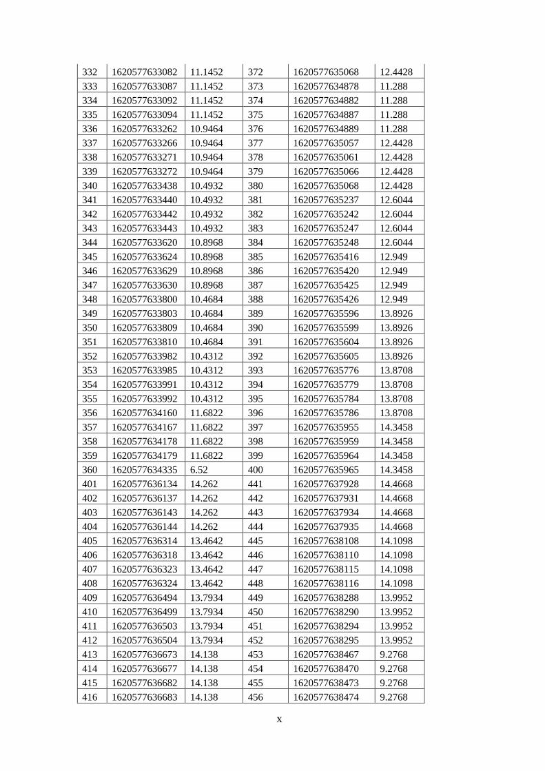


![HIGH BEAM [OUTDOOR]](https://static.documents.pub/doc/80x56/616a05cc11a7b741a34df4d0/high-beam-outdoor.jpg)

