IN DEGREE PROJECT DESIGN AND PRODUCT REALISATION, SECOND CYCLE, 30 CREDITS , STOCKHOLM SWEDEN 2019 Design for Additive Manufacturing - A methodology MALIN SANDELL SAGA FORS KTH ROYAL INSTITUTE OF TECHNOLOGY SCHOOL OF INDUSTRIAL ENGINEERING AND MANAGEMENT
Transcript
IN DEGREE PROJECT DESIGN AND PRODUCT REALISATION,SECOND CYCLE, 30 CREDITS
, STOCKHOLM SWEDEN 2019
Design for Additive Manufacturing - A methodology
MALIN SANDELL
SAGA FORS
KTH ROYAL INSTITUTE OF TECHNOLOGYSCHOOL OF INDUSTRIAL ENGINEERING AND MANAGEMENT
Design for Additive Manufacturing - A methodology
Malin Sandell Saga Fors
Master of Science Thesis TRITA-ITM-EX 2019:289 KTH Industrial Engineering and Management
Machine Design SE-100 44 STOCKHOLM
Examensarbete TRITA-ITM-EX 2019:289
Design för Additiv Tillverkning – En metodik
Malin Sandell
Saga Fors
Godkänt
2019-05-27
Examinator
Claes Tisell Handledare
Martin Sjöman
Uppdragsgivare
Konfidentiellt Kontaktperson
Konfidentiellt
Sammanfattning Additiv tillverkning (AM), även kallat 3D-printing, är benämningen på en grupp tillverkningstekniker där en produkt byggs lager för lager. Denna masteruppsats har utförts i samarbete med ett svenskt industriföretag som levererar lösningar inom tillverkningsindustrin, i rapporten kallat Företaget. Genom att utveckla nya designprocesser och metoder vill Företaget inkludera AM i sin tillverkningsstrategi. Syftet med detta masterexamensarbete var att utveckla en metodik för hur urval och utveckling av produkter anpassade för AM ska ske.
Utvecklingen av metodiken följer principerna för tjänstedesign, vilket innebär ett holistiskt tvärvetenskapligt arbetssätt där metoder från olika discipliner kombineras för att skapa en positiv upplevelse för slutanvändaren. Innan utvecklingsprocessens start gjordes en stor bakgrundsstudie för att införskaffa kunskaper kring AM. Därefter utvecklades en metod genom fem iterativa cykler där metoder som intervjuer, triggermaterial, frågeformulär, fallstudier och stakeholdermapping användes.
Masteruppsatsen resulterade i en handbok med information kring teknikerna och en metodik i fem steg för att välja när och varför AM bör användas som tillverkningsmetod. Första steget är att identifiera AM potentialen hos en produkt, vilket baseras på komplexitet, kundanpassning och produktionsvolym. I steg två ska produktkrav specificeras, exempel på sådana krav är ytfinhet och toleranser. Tredje steget i metoden handlar om en produkt-undersökning under vilken ett slutgiltigt beslut fattas angående om produkten kan och bör tillverkas. I fjärde steget sker valet av teknik baserat på de produktkrav som specificerats i steg två, genom att information ges angående teknikens möjligheter och begränsningar. Femte steget i metoden handlar om designen av AM produkter och förser konstruktören med enklare riktlinjer för designen.
Utveckling av en metodik kräver ett dynamiskt arbetssätt och principerna inom service design visade sig passa bra för detta projekt. Det visade sig också att den resulterade metodik behöver kompletteras med information i framtiden. Det behövs även fastställas tydliga mål för AM i företaget och vilket syfte implementeringen av denna nya process innebär
Master of Science Thesis TRITA-ITM-EX 2019:289
Design for Additive Manufacturing – A methodology
Malin Sandell
Saga Fors
Approved
2019-05-27 Examiner
Claes Tisell Supervisor
Martin Sjöman
Commissioner
Confidential Contact person
Confidential
Abstract Additive manufacturing (AM), sometimes called 3D-printing is a group of manufacturing technologies that build up a product using a layer by layer technique and provides new ways of manufacturing parts and products. The Company in this thesis wants to make AM a tool in their manufacturing toolbox. When introducing this manufacturing method, new processes and methods have to be developed. The purpose of this thesis is to develop a methodology that will help the designers when identifying parts that should be manufactured using AM.
The development of this methodology has followed the principles of service design which is a holistic interdisciplinary approach where methods from different disciplines are combined to create benefits to the end user experience. Before the development process, a large background study was performed to gather detailed information within the area of AM. The methodology concept was then developed through five iterative cycles where methods such as interviews, trigger material, questionnaire, case study and stakeholder mapping were used.
The thesis resulted in an AM handbook with information regarding the technology and a five step methodology for choosing when and why to use AM as a manufacturing method. Step one is to identify the AM potential in a product which is based on complexity, customization and production volume. Step two is to specify requirements of the products, this can be surface finish, tolerances etc. The third step in the design methodology is part screening, which is the making of the final decision about if the product should be printed and if it can be printed. The fourth step is to choose an AM technology based on the requirements specified in step two by providing information about the technologies’ restrictions and possibilities. Step five in this methodology is the design of AM products and provides simple design guidelines.
It has been shown that a dynamic task is best solved through working with dynamic methods, therefore service design approach is a flexible and good fit for this thesis. This design methodology is only a part of the AM-area and needs to be supplemented with other knowledge within the area. The first step after implementing this handbook is to investigate how the organization and business is affected when implementing AM.
NOMENCLATURE
Abbreviations
3D 3 Dimensional
2D 2 Dimensional
SLS Selective Laser Sintering
SLM Selective Laser Melting
MJF Multi Jet Fusion
BJ Binder Jetting
AM Additive Manufacturing
DfAM Design for Additive Manufacturing
CAD Computer Aided Design
SLA Stereolithography
DLP Digital Light Processing
CDLP Continuous Digital Light Processing
LOM Laminated Object Manufacturing
EBM Electron Beam Melting
MJ Material Jetting
NJP NanoParticle Jetting
DOD Drop On Demand
FDM Fused Deposition Modeling
LENS Laser Engineering Net Shape
EBAM Electron Beam Additive Manufacturing
TABLE OF CONTENTS 1 INTRODUCTION .................................................................................................................. 1
APPENDIX J: Step three: Part Screening - Appendix .............................................................. 1
APPENDIX K: Step four and five: Choice of technology & Design Guidelines – Appendix .. 1
1
1 INTRODUCTION In this chapter the reader will be given an introduction to the thesis, with a background as well as the purpose, delimitation and methods used.
1.1 Background The Company is a Swedish world leading supplier of solutions to manufacturing industries such as general engineering, manufacturing and process, construction, automotive, electronics, oil and gas. They provide products such as compressors, vacuum pumps and handheld tools to customers in more than 180 countries and has done so for more than 100 years. The Company has a long history of conventional manufacturing, using tools such as milling, welding or drilling for their products. These manufacturing methods are sometimes called subtractive manufacturing because they subtract material in order to create 3D (3-dimensional) objects. Additive manufacturing (AM) is a group of manufacturing technologies that build up a product using a layer by layer technique, adding material instead of subtracting it, see Figure 1.1 for a comparison between conventional manufacturing and AM.
Figure 1.1 - Comparison between subtractive manufacturing and AM (3dnatives)
Apart from contributing to less waste material than conventional manufacturing AM has a lot of potential such as high design freedom and the opportunity to manufacture complex parts, see chapter 2.1.3 Potential use of AM. The great possibilities of AM is followed by challenges such as how to make it cost effective as well as analysing when and how the method should be implemented to the designers (Conner et al. 2014, 64-76). AM provides new ways of manufacturing parts and products, but it also brings uncertainty from the design perspective. There are design strategies available that will guide the designers in developing products with a focus on conventional manufacturing methods. However, these design guidelines are not directly adaptable to AM. Processes and methods has to be developed to be able to introduce a new design strategy, Design for Additive Manufacturing (DfAM). (Bourge, Panarotto and Isaksson. 2018, p 997).
2
1.2 Purpose The purpose of the thesis is to develop a methodology for DfAM that will help the designers at The Company to understand when and why to use AM as a manufacturing method. It should also help them in their decision making when designing parts for AM and encourage them to use it as a tool for product development.
1.3 Objectives The methodology shall provide information as well as guidelines for how a product or a part should be designed or redesigned for AM, which technology and material to use, what manufacturing restrictions and opportunities exists. Both the information and the guidelines need to be adapted to the designers needs at The Company and the way they work today.
1.4 Delimitations According to Senvol database there are more than 1180 varieties of AM machines and 2317 different materials available (Senvol). Each machine is suitable for different applications and choosing the correct one for the purpose is important. Knowledge and experience is also important in order to make good decisions, which could make the choice a difficult task for new users (Wang, Blache and Xu 2017).
The Company wished for a methodology that covered both polymer and metal AM. In this thesis a limitation has been done to focus on four AM technologies, two metal technologies: Selective Laser Melting (SLM) and Binder Jetting (BJ), as well as two polymer technologies: Selective Laser Sintering (SLS) and Multi Jet Fusion (MJF). This limitation has been made based on recommendations from the experts met on the field studies, see chapter 2.2 Field studies. The decision was also made based on the fact that these are all common technologies that have been tested by designers at The Company with good results. It was decided to focus on technologies that can be used to create both functional prototypes and end-use-products, as well as visual prototypes.
Another aspect that has not been included in the thesis is the validation of quality and functionality of AM produced parts or the making of drawings and other material that the suppliers need. This is an area of AM that needs further research and is under development, see chapter 2.1.5 AM Design Considerations. It is also an area where The Company needs to make decisions regarding collaborations with suppliers as well as how they want to handle their material and the transfer of this to the suppliers, see chapter 6. Future work.
The resulting methodology will be a first version that needs further development and updates as the knowledge within the AM area grows. This is a natural part of any new project, the development is a continuously ongoing process.
3
1.5 Method The process of creating the design methodology followed the principles of service design which is different from the traditional academic way of thinking (Stickdorn and Schneider 2014). This way of working has no common definition yet but is flexible and focused on developing services for the user (Stickdorn and Schneider 2014). It is not about asking the users what they want, but rather to understand user needs and developing solutions for this (Granfelt Laurén and Borell 2018).
The user in this thesis has been the designers at The Company and the design methodology has been the service which is described more in detail in chapter 4. Result. Stickdorn and Schneider (2014) present in their book This is design thinking, eight different definitions of the subject which can be summarized as:
Service design is a holistic interdisciplinary approach where methods from different disciplines are combined to create benefits to the end user experience. This is made through the use of intangible and tangible mediums and is applied to, among other things, banks, transport and retail organizations. It is used to develop new and improve already existing services in order to make them more user-friendly, efficient, useful and desirable while facilitate the organization.
The book also describes five aspects of service design:
1. User-centered - Services should be experienced through the customer’s eyes.
2. Co-creative - All stakeholders should be included in the service design process.
3. Sequencing - The service should be visualized as a sequence of interrelated actions.
4. Evidencing - Intangible services should be visualized in terms of physical artefacts.
5. Holistic - The entire environment of a service should be considered.
The service designer needs to work iteratively in order to develop solutions that fit the user needs (Stickdorn and Schneider 2014). An iteration is another word for repetition and describes the process of repeating something in order to improve the result (Cambridge dictionary 2019). A simple way of describing one iteration is that something is first designed then tested, if the result is not satisfying the process is repeated with a redesign and new testing, see Figure 1.2.
Figure 1.2 - One iteration in two steps, designing and testing. Illustration made by thesis authors
There are many ways of describing a design process. One well-established process that can be used in service design projects is the Stanford d.School design thinking process, see Figure 1.3.
4
This method uses the same iterative workflow as described above, but broken down in five steps, and is used to develop innovative solutions to problems (Plattner, H). This method has been used in this thesis.
Figure 1.3 - The Stanford d.School design thinking process (Plattner, H)
The empathize phase in the process focus on getting to know the person that the service is designed for, how and why the person do things. The information found in the empathize phase is later defined as user needs in the define phase. The defining phase is all about finding patterns in the customer’s behavior and understand who the customer is. The next step is to ideate solutions that will meet the user need and behavior. These solutions are later visualized as prototypes. The purpose of the prototype is to share the proposed solutions with the users in order to get feedback. Then finally the solution needs to be tested and feedback received from the prototype. (Plattner, H)
In this thesis the process has been done in collaboration with the designers at The Company in different iterations. The thesis has moved forward through the five steps, although some steps have been repeated in iterations in order to get results closer to what the employees wish for. See chapter 3. Implementation for a more specific description of how the method was used in this thesis.
The thesis started with a literature review, web research and two field studies to gather detailed information within the area of AM. The information from the field studies was obtained through observations and interviews. Thereafter, interviews were carried out with designers at The Company in order to get an understanding of the user, which is the key in service design. The methodology concept was developed through iterations where interviews were combined with trigger materials. The concept was evaluated by the designers that had been interviewed through a survey. A case study was also performed where a product from The Company’s product range was redesigned for AM, based on the created design methodology. The purpose of the case study was to test the methodology and make some final changes. The used methods will be described briefly in the following sections and presented in detail later in the report.
1.5.1 Literature Review & Web Research The purpose of a literature review is to get a review of the state of the research today, within the subject of AM. It is also used to gain knowledge from the scientific articles and books published within the research area (Milton 2013). The literature review and a web research was performed with the purpose of gaining a deeper knowledge of the subject.
5
The Internet provides endless possibilities when gathering information within the chosen research area, however, it is important to be critical. Materials found on the internet should be reviewed according to the following questions (Milton 2013):
● Is there an author or is the source anonymous? ● What education or profession does the author have? ● Is the author linked to known intuition, education or newspaper? ● Does the information seem right? ● When was the source updated? ● Is the information objective? ● Is the information posted for promotional purposes? ● What audience is the information aimed for?
Keywords used were: AM, Additive Manufacturing, Design for additive manufacturing, DfAM, when to use, business, industry, production, benefit, challenges, methodology, design, strategy, technology, material, part selection, part screening and post process. To learn more about the result of the Literature Review and Web Research, read chapter 2.1 Literature Review & Web Research.
1.5.2 Field Studies Field studies were performed to gain an understanding of how other companies work with the same issue and learn from their weaknesses and strengths. It can also be used to gather information and knowledge about something that cannot be found with other information searching methods. Often, a visit is made at a company where a walk trough of the business is performed with the possibility to ask questions. (Milton 2013)
In this thesis, two field studies were made at two different companies. Three days were spent at Company A, who are focusing their business on development and implementation of AM through research and manufacturing. The purpose of the Company A visit was to gain knowledge about the AM technologies that they use (SLM and SLS) but also get an understanding of when to use AM. One afternoon was spent at Company B, which is a supplier of AM details in Sweden and work with both polymer and metal technologies. The visit to Company B was focused on understanding what the suppliers want and need from companies in order to manufacture parts and products. To learn more about the result of the field studies, read chapter 2.2 Field Studies.
1.5.3 Interviews A common way of getting qualitative data is to do interviews with the users of the product or methodology. In this thesis both unstructured and semi-structured interviews were used. The semi-structured interviews are based on pre-written questions to keep the interview within the desired area but allowing the interviewee to contribute with other information if desired. The unstructured interviews are based on open ended questions, allowing the interviewee to discuss and explain the main issue (Milton 2013).
6
Three rounds of interviews with six to seven designers were performed with the purpose to gain new insights or test concepts. The first interview had the purpose of learning more about The Company as well as their employees, work environment and general knowledge about AM. The second round focused on learning more about their product design processes through the usage of trigger material. The third round of interviews were performed with the purpose of testing/evaluating concepts. Trigger material was used here as well. The interviews with the designers were an important part of the thesis since the design methodology was adapted to them. The interviews were recorded and transcribed in order to empathize and define the information properly. To learn more about how the interviews were used in the thesis, read chapter 3. Implementation.
1.5.4 Trigger Material Trigger material is a visual material that can be used as an aid during an interview in order to provoke a reaction or opinion, create discussion and test an idea or to co-create (Granfelt Laurén and Borell 2018). It was used two times in this thesis to test the concept and provoke reactions or/and opinions about the content in the methodology. The first time trigger material was used it was in the shape of a blank paper and an empty stakeholder map. The second time it was a draft of a printed handbook with chapter headlines, some illustrations and a few post-it’s with some ideas on the content of the handbook. To learn more about how the trigger materials were used in the thesis, read chapter 3. Implementation.
1.5.5 Observation An observational research method is used to understand how people act and what they really need. Observing people in their natural environment rather than in a research environment gives a deeper knowledge and reveals a complexity that cannot be explained with words. The researcher is sitting beside the user and observing how the person works. This gives an indication of which parts of the work process that are difficult and which parts are easy. The researcher takes notes and asks questions if needed during the observation. (Milton 2013)
In this thesis observations were done during the field study at Company A. Observations were made with an AM designer that prepared files for AM production, with focus on orientation and support material. The purpose of this was to gain an understanding of how a designer with experience of AM product design thinks and what aspects he or she takes into consideration.
1.5.6 Questionnaire A questionnaire is a list of questions and used as a method to collect quantitative data. Questionnaires are a time efficient way of getting information from people but does usually have low response rate. (Milton 2013)
The design methodology created in this thesis was tested through a questionnaire that was sent out to 13 designers at The Company. The purpose of the questionnaire was to let the designers evaluate the concept after they had tested it.
7
1.5.7 Stakeholder mapping A stakeholder map is a visualization of the stakeholders involved during a particular service. It can be managers, customers, users or others who may be relevant for the service. This can be used to analyse and chart the interaction between different stakeholder groups (Stickdorn and Schneider 2014). A stakeholder map has been used in this thesis to analyse the stakeholders involved during the product design process at The Company.
1.5.8 Case study This method is used to test theoretical methods and concepts through using them in practical environments but can also be used to present and analyse data. A case study was performed with a product from The Company with the purpose to test the resulting concept. This product was evaluated and then redesigned for AM, using the design guidelines. The purpose of this was to test the methodology and see how well it worked, if something needed to be changed or added.
8
9
2 FRAME OF REFERENCE The information presented in this chapter has been used as a background for decision making while developing the AM design methodology.
2.1 Literature Review & Web Research
The findings from the literature review and web research has been categorized into five different categories:
● History of Additive Manufacturing ● Technologies ● Potential use of AM ● AM design benefits ● AM design considerations
2.1.1 History of Additive Manufacturing
AM, also referred to as 3D-printing, is a term that refers to the technologies of creating parts by adding layers of material, where each layer is a thin cross section of the wanted geometry, see Figure 2.1.
Figure 2.1 - AM part being manufactured layer by layer (Materdome3D)
The part is created from a 3D model in a Computer Aided Design (CAD) system. Since this cross section has a material thickness, the final product will not be a perfect copy of the original geometry. Imagine creating a ball through cutting circles of paper and gluing them together. You start with a small circle and then adding a larger circle on top of it. This change in dimension will result in a change in the overall surface as well. The final ball will not have the same perfectly smooth surface as one that has been molded. The thinner each material layer is, the smoother the surface of the final part will be. (Gibson, Rosen, Stucker 2015)
10
Today there are multiple AM technologies that differ in their way of creating and adding layers as well as their material options, see chapter 2.1.2 Technologies. These differences will affect the final accuracy, mechanical properties, size, production time as well as the amount of post processing needed. (Gibson, Rosen, Stucker 2015)
Since the introduction of AM to the general industries, the technologies have developed a lot in terms of accuracy, materials and overall quality. Throughout its history AM has been used for validation but with different purposes. Today it is mainly used to validate three things, the three F’s (Gibson, Rosen, Stucker 2015). AM was firstly used to make physical visualizing models, to help validation of design as well as communicate the designers intent in a way that sketches could not. This validation refers to validation of the first F, the Form (Gibson, Rosen, Stucker 2015). Fit is the second F and is something that AM has been used for as the technology became more dimensionally and geometrically accurate in terms of surface finish and tolerances (Dosser et al. 2017). When using AM for the purpose of validating form and fit it is usually done in a prototyping stage, with the purpose of manufacturing the final product through conventional methods. The third F, Function, refers to AM products that are made with the purpose of working in a final stage. This final F makes it clear that the AM technology is ready not only for testing prototypes but for end-use products as well. (Gibson, Rosen, Stucker 2015)
AM technologies have been used for rapid prototyping in many years, but for the last years it has also been used for industrial manufacturing (Dosser et al. 2017). AM was first introduced in 1987 with a technology called stereolithography (SLA) (Wohlers and Gornet 2014). Since then multiple other technologies have been developed. Since 2004 patents have expired and are still expiring, which was important for the development of the AM technologies. The expiration of patents has resulted in the development of cheaper and smaller machines, commercially accessible and introducing new, smaller companies to the market. This accessibility and cost reduction resulted in a growth of interest for the technologies. From this, the amount of accessible information and available online 3D printing services increased. Finally, with the growing interest the competition between firms also intensified, resulting in improved patents and faster and better machines. (Sculpteo 2016)
According to a study by Sculpteo (2018), 55% of the total AM application is in prototyping but 43% of the application is actually in production. The study had 1000 respondents from different industries such as:
● Industrial goods (17%) ● Consumer goods (12%) ● Aeronautical or Aerospace industry (7%) ● Healthcare and Education/Student (6%) ● Automotive, High tech, Mechanic & metal (5%)
The majority of the respondents were engineers or CEO/owners. What is interesting is that the market för AM is growing rapidly, 37% of the respondents were expecting to increase the AM expenses in 2018 by 1 to 50%, and 19% were expecting to increase them more than 100% the following year. Also, 93% of the respondents considered AM to be a competitive advantage.
11
According to the study the 3D printing related areas that are prioritized the most are: accelerating product development, offering customized products and limited series and increasing product flexibility. These are also the areas in which the organizations could improve the most.
2.1.2 Technologies Today there are multiple AM technologies available, catalogued into seven groups: binder jetting, directed energy deposition, material extrusion, material jetting, powder bed fusion, sheet lamination and vat photo polymerization (Wang, Blache, Xu 2017). All of these technologies have different technologies and material options, see Figure 2.2.
Figure 2.2 - AM technologies and technology groups. Illustration made by thesis authors
In this thesis a limitation has been done to only focus on four AM technologies, Selective Laser Sintering (SLS), Selective Laser Melting (SLM), Multi Jet Fusion (MJF) and Binder Jetting (BJ), see chapter 1.3 Delimitations. All of these technologies build parts layer by layer through first spreading a thin layer of material powder on a base plate and fuse the powder in a pattern representing a cross section of the final product. What sets the technologies apart are the different methods they use to perform this fusing.
12
Three of the chosen technologies, SLS, SLM and MJF, are based on the AM method called powder bed fusion. This method uses a thermal source to fuse material powder into a solid part. SLS and SLM both use a laser as their thermal source, see Figure 2.3. The main difference between SLS and SLM is that SLM uses metal powder whereas SLS use polymer powder. (3D Hubs)
Figure 2.3 - SLS and SLM technology (3D Hubs)
MJF uses a combination between a fusing agent and a high-power IR energy source. An inkjet nozzle depose the fusing agent on the thin layer of powder, in a pattern resembling a cross section of the wanted part. Another nozzle depose a detailing agent around the edges of the cross section, to prevent nearby material from sintering. The sintering of the cross section is then performed by the IR energy source, see Figure 2.4. MJF only produce parts made of polyamide powder. (3D Hubs)
Figure 2.4 - MJF Technology (The Technology House)
13
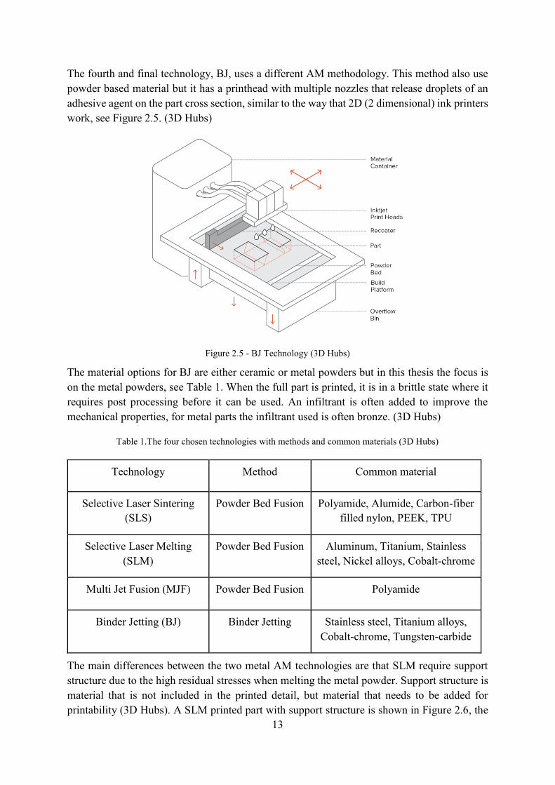
The fourth and final technology, BJ, uses a different AM methodology. This method also use powder based material but it has a printhead with multiple nozzles that release droplets of an adhesive agent on the part cross section, similar to the way that 2D (2 dimensional) ink printers work, see Figure 2.5. (3D Hubs)
Figure 2.5 - BJ Technology (3D Hubs)
The material options for BJ are either ceramic or metal powders but in this thesis the focus is on the metal powders, see Table 1. When the full part is printed, it is in a brittle state where it requires post processing before it can be used. An infiltrant is often added to improve the mechanical properties, for metal parts the infiltrant used is often bronze. (3D Hubs)
Table 1.The four chosen technologies with methods and common materials (3D Hubs)
The main differences between the two metal AM technologies are that SLM require support structure due to the high residual stresses when melting the metal powder. Support structure is material that is not included in the printed detail, but material that needs to be added for printability (3D Hubs). A SLM printed part with support structure is shown in Figure 2.6, the
14
support structure is all the material with the honeycomb structure. Support material is often made in structures like the one shown in Figure 2.6 to save material, time and costs. The support material is marked with the red ring. Support structure transports the heat and is removed through post processing. Orientation of the part in the printer chamber and design of the product can minimize the amount of support material. (3D Hubs)
Figure 2.6 - AM manufactured detail with support material (marked with the red ring) (The Manufacturer)
Part orientation and placement of support structure is also important and therefore the data file preparation is more time consuming. BJ does not need support structure, the support from the powder bed is enough and there is no heat treatment involved in the manufacturing process. This also means that parts can be stacked on top of each other with only a few layers of powder separating them. This phenomenon is called nesting and can be done in BJ, SLS and MJF. (3D Hubs). Figure 2.7 shows a nesting of bicycle pedals.
Figure 2.7 - Nesting of bicycle pedals in a SLS printing chamber (Formlabs)
Another advantage with BJ is that assemblies of parts and kinematic joints can be produced since the loose powder can be easily removed. Nesting is not possible for SLM and assemblies of parts as well as kinematic joints are harder to produce than with BJ due to the support structure. It also common that SLM produced parts shrink with a few percentage, which can lead to some part distortion. BJ does not shrink during the manufacturing process but the sintering post-processing can result in a shrinkage of up to 20%. This is compensated for in the machine software but can result in accuracy problems due to uneven sintering.
15
BJ is a lot more economical than SLM and has shorter lead times. On the other hand the mechanical properties are not as good and details may break since they are very brittle in the early state, before post processing. (3D Hubs)
The main difference between the two plastic AM technologies are the heating source, since SLS uses a laser and MJF the fusing agent in combination with infrared light. The result of the technologies are similar otherwise. Both have high accuracy, does not need support structures, costs are similar, both technologies face the risk of warping and the resulting product will have a slightly grainy surface that can be post-processed. MJF has slightly more homogenous mechanical properties in all directions although SLS have more material options and is studied and documented to a greater extent. MJF also has shorter lead times than SLS. (3D Hubs)
2.1.3 Potential use of AM
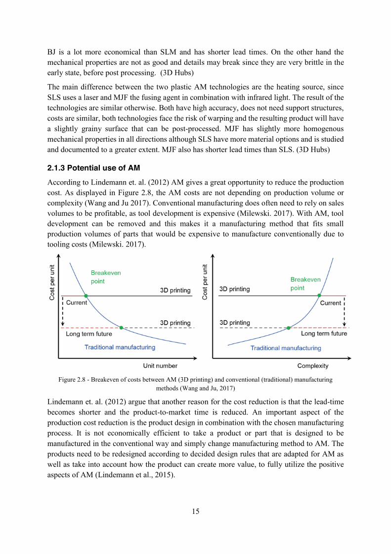
According to Lindemann et. al. (2012) AM gives a great opportunity to reduce the production cost. As displayed in Figure 2.8, the AM costs are not depending on production volume or complexity (Wang and Ju 2017). Conventional manufacturing does often need to rely on sales volumes to be profitable, as tool development is expensive (Milewski. 2017). With AM, tool development can be removed and this makes it a manufacturing method that fits small production volumes of parts that would be expensive to manufacture conventionally due to tooling costs (Milewski. 2017).
Figure 2.8 - Breakeven of costs between AM (3D printing) and conventional (traditional) manufacturing
methods (Wang and Ju, 2017)
Lindemann et. al. (2012) argue that another reason for the cost reduction is that the lead-time becomes shorter and the product-to-market time is reduced. An important aspect of the production cost reduction is the product design in combination with the chosen manufacturing process. It is not economically efficient to take a product or part that is designed to be manufactured in the conventional way and simply change manufacturing method to AM. The products need to be redesigned according to decided design rules that are adapted for AM as well as take into account how the product can create more value, to fully utilize the positive aspects of AM (Lindemann et al., 2015).
16
The choice of which part that is to be manufactured with AM is crucial in order for the process to be cost-effective (Lindemann et al., 2015). This process should be performed before the design process (Kumke et al., 2017). Conner et al. (2014) has identified three main criteria for a strategic AM part identification; production volume, customization and complexity. Production volume, customization and complexity should be the first three attributes to be analysed and will give a general idea regarding AM potential early in the project (Kumke et al., 2017). Production volume refers to the number of products manufactured during a given period of time. It can be millions of aluminum cans manufactured in one year or a single unique injection molded product. Customization refers to the products that are adapted to a unique need, for example it can be a prosthesis or bite rail. The complexity of a product is determined by the number of functions that are present in the product and how they are located. A reference system is shown in Figure 2.9 where the three attributes shows the reference frame of manufacture. (Conner et al., 2014)
Figure 2.9 - The manufacturing reference system with the eight manufacturing aspects (Conner et al., 2014)
The eight different manufacturing aspects shown in Figure 2.9 are:
1. Mass manufacturing has been the primarily focus in conventional manufacturing. Mass manufactured products are often simple parts or assemblies of multiple simple parts. There is no customization to obtain low production costs, because assembly lines and tools such as molds or fixtures are expensive. Before a part is to be mass-produced, a tool for the specific part is often manufactured, which contributes to long lead times and big tool investments costs. Although the tools are expensive, the production of millions of products justify the tool costs. Mass production is an established business model, it contributes to a low cost per produced part and is cost driven. Due to the lack of complexity and customization of products within the region of mass manufacturing, products in this region should not be manufactured with AM. (Conner et al., 2014)
17
2. Manufacturing of the few refers to the products that have low complexity and customization, similar to the products of mass manufacturing. The difference is that these have low production volume as well. The definition of low volume is not a strict number and it differs between industries and companies. In the vehicle industry, the upper number of low volume is 30 000 vehicles per year and in the aerospace sector this number about 200 aircrafts per year. It is a good advice to use the high or low production definitions based on industry. To be able to conduct a discussion, 10,000 units produced per year is defined by Conner et al. (2014) as a low production volume. The use of AM in the region will, in comparison to conventional manufacturing, result in lower production costs and reduced lead times. (Conner et al., 2014)
3. Complexity advantage is where the products with high complexity is described. High complexity in a product can increase functionality or provide a pleasing appearance. Multiple operations and different tools are required to manufacture complex products using conventional manufacturing, which also increase production times. The other way to manufacture complex products using conventional manufacturing is to manufacture less complex parts and assemble these into a product with high complexity. Products that are assembled using joints often have lower durability than products that are manufactured as one unit though, and higher assembly cost and overall lead times from order to finished product. Due to the increase in costs when manufacturing complex products, these are usually found in the medicine or aerospace industry. The reason for this is because an increased cost can be justified by the fact that the performance is increasing. With AM there is much higher complexity freedom compared to conventional manufacturing. Complex functions or geometries that are difficult to manufacture with conventional manufacturing methods could sometimes with simplicity be produced by AM. Some examples are:
● Functions like deep canals and varying wall thickness
● Complex geometries such as internal holes or arced walls
● Topologically optimized shapes and integrated moving parts
This makes it advantageous to manufacture complex products when AM is chosen. (Conner et al., 2014)
4. Mass complexity describes the complex and high volume produced products that are not customized. Hip replacement and cups for implants are examples of products that has mass complexity and are produced of the-shelf. Although AM is not best suited for high volume, if the product is very complex it can still be beneficial to use AM instead of conventional manufacturing methods within this area. (Conner et al., 2014)
18
5. Products that are customized for the individual has low complexity and low volume but high customization. Examples of these products are prosthetics with low complexity or when repairing parts with low complexity. Conventional manufacturing is often not advantageous when customized parts are to be manufactured. It is expensive to manufacture the tools and lead times are often longer on the tools than on the product itself. Therefore, AM has great potential in this area. AM is a key enabler to manufacture products according to the customers’ needs without using expensive tooling or fixtures. Symmetry and simplicity are beneficial when it comes to conventional manufacturing. Making complex products with conventional manufacturing methods is expensive and time-consuming. Having the opportunity to manufacture tailor-made products is important for society though. AM makes it possible to manufacture complex products and tailored products in a short time and with lower costs than with conventional manufacturing. (Conner et al., 2014)
6. With mass customization it can be beneficial to use AM. Conventional manufacturing is not advantageous to use when customized parts are to be manufactured. It is expensive to manufacture the tools and lead time is often longer on the tools than on the product itself. Therefore, AM has potential in this area. AM makes it possible to manufacture products according to the customer's needs without using expensive tools. (Conner et al., 2014)
7. The products in the artisan area are rather artworks than functional products, but can also include Formula One racing car components or complicated prostheses. AM provide new opportunities within this area due to its high design freedom. (Conner et al., 2014)
8. Products with complete manufacturing freedom is as of now not commercially available within AM. This will be fulfilled when it’s possible to produce products with high complexity that are highly customized without build volume limitations, as well as taking production volume and business models into consideration. Today AM is limited by for example the production rate and build volume, more research and development is needed to improve the processes. (Conner et al., 2014)
2.1.4 AM design benefits
AM provides design opportunities that conventional manufacturing does not, but the product or component needs to be redesigned and adapted for AM. The designer needs to know the answer to the question of how the product can create value and how to design it in order to utilize the positive aspects. Utilizing the full potential that AM technologies offer is an important part of the DfAM process (Lindemann et al., 2015).
19
Complex assemblies can often be integrated from several parts into one component with AM. By adding clearance around moving parts, mounting of hinge, chains and other moving constructions can be done as one part. Therefore, mounting complexity can be reduced when using AM (Gibson, Rosen, Stucker, 2010), which can save both time and money. See Figure 2.10 for a picture of a chain that is manufactured as one part.
Figure 2.10 - A chain printed as one part, example of integrated assembly (Zedax)
With the help of AM, complex internal features can be created, which in some cases may be impossible with conventional manufacturing. For example optimized cooling fluid channels or integrated air ducts can be created (Durakovic. 2018, 183-184), see Figure 2.11.
Figure 2.11 - AM manufactured part with complex internal structures (Popularmechanics)
AM also makes it possible to manufacture optimized geometry based on numerical optimization and simulation, topology optimization. Through this, the material is placed only in the places where it is needed, in order to achieve desired functionality. This is a useful application when minimized weight is a significant factor for the product (Durakovic. 2018, 183-184). A hydraulic block that has been redesigned with topology optimization to lower the weight is shown in Figure 2.12.
Figure 2.12 - A hydraulic block that has been topology optimized to lower the weight (gkn powder metallurgy)
20
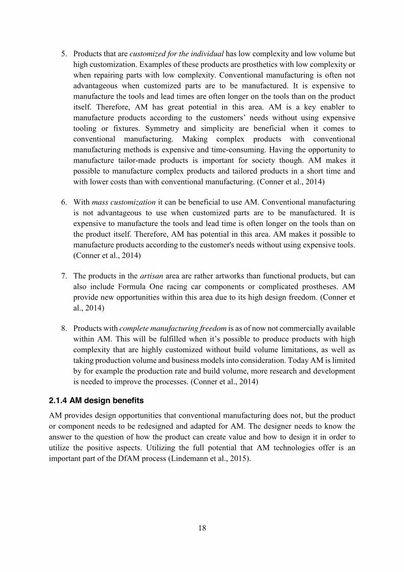
Another example of how the functionality can be improved through the geometrical benefits with AM is the creation of cellular materials. Cellular materials are materials with voids of structures that can create stiff, high-strength products with low mass. These cellular materials also provide good energy absorption as well as good thermal- and acoustic insulation (Rosen, 2014). The cellular materials are built in lattice structures, a structure made out of crossing patterns such as honeycombs or triangles (Recrosio, 2017), see Figure 2.13.
Figure 2.13 - AM product with internal lattice structure (Noizear)
2.1.5 AM design considerations
One area of concern when looking for potential use of AM is organization and implementation (Ruffo et al, see Mellor, Hao and Zhang 2013). There are limitations with AM that have to be taken into account and new design rules must be implemented early in the design process. The requirements for the product, such as surface finish, dimensional accuracy and force stress, must be clearly specified at an early stage. In order to make these decisions at an early stage of the design process, good knowledge and deep understanding of the manufacturing method with its benefits as well as drawbacks are required.
One difficulty with DfAM is that the designers need to look past their previous knowledge regarding design for conventional manufacturing and learn how to design for AM instead. Bourge, Panarotto and Isaksson (2018) found that there are many DfAM methods that are developed with the aim of supporting designers to design for AM. These methods often focus on generating new innovative designs and geometries, utilizing all new opportunities and capabilities with AM, which can make it difficult for designers to make decisions as they compare it to conventionally manufactured parts. They argue that in order to make a decision, the new design must prove to be better than the old one. A better design can be done by, for example, creating a higher performance, functionality or reducing the number of assembly parts thus reducing the manufacturing steps. This can be facilitated by having the same requirements and limitations on products manufactured with AM as on the product which is usually manufactured in the conventional way (Bourge, Panarotto and Isaksson. 2018, p 1002-1003).
21
There are a few design considerations that needs to be taken into account when designing a part for AM. Different technologies have different design considerations (3D Hubs), but this chapter focuses on the main considerations. These considerations are shown in Figure 2.14.
Figure 2.14. Design considerations for AM. Illustration made by thesis authors
The wall thickness refers to the fact that it cannot be too thin walls on a detail that is to be manufactured with AM. It is the same thing with pin diameter and hole size diameter, in order for the manufacturing method to give a good result, neither the pin diameter nor the hole diameter can be too small (3D hubs). If a hole is printed in the Z-direction it can be reshaped with an almond shape, see Figure 2.15. The almond shape is self-supporting due to its shape and does not need support structure. A hole can also be post processed by drilling in order to get the right size and finish (Paluzie Noe 2019).
Figure 2.15 - A hole with support structure to the left and a redesign of a hole to the right. (Paluzie Noe)
AM can result in material deformations when melted and solidified, a phenomena called warping. This is caused by internal material stresses during cooling of the manufacturing
22
process. There is a great risk that the material will warp if the part consists of large, long and flat surfaces. The warping can be avoided by orienting the detail differently in the printer, having enough support material that holds it in place and through heat processing. (3D hubs) Figure 2.16 shows how warping can look like.
Figure 2.16 - Warping of a plastic part (Prusa3D)
Overhangs are the part of the model that do not have support of material from below. All printers can manufacture different angles without the need of support material, but a rule of thumb is to not exceed 45 degrees (3D hubs). See Figure 2.17 for an explanation of what can happen with too much overhang without support structure.
Figure 2.17 - Overhangs in additive manufacturing (Solidworks)
Powder based AM technologies that have hollow parts or internal structures need escape holes through which excess powder can be removed. (3D Hubs)
To achieve desired final result, post-processing is often needed with most AM technologies. If support material is used, post-processing is always needed to remove it. Many technologies produce parts with good properties and surface qualities but often post-processing methods such as dyeing or polishing are used. Post processing can also make some components watertight and improve mechanical properties (3D hubs).
23
Orientation in the AM context means how the detail is placed in the print chamber. The orientation can affect the price of the product, the material characteristics of the component and the printability. The printability refers to the angle to the recoater, the part that spreads the powder. It is important to ensure that the detail is not placed parallel with the recoater, nor that the detail is built towards the recoater, see Figure 2.18. If the detail is placed parallel to the recoater, the powder will be distributed unevenly. (Paluzie Noe 2019).
Figure 2.18 - Orientation seen from the top (left) and from the side (right). Illustration made by thesis authors
Orientation can also affect the price of the product. It is the print time and the powder consumption that decides the costs, therefore it is best to place the item so that the height of the print becomes as low as possible (Paluzie Noe 2019). Quality aspects such as surface finish, accuracy and the ability to remove support material can also be affected by the orientation. Along the Z axis, print lines can occur, therefore it is good to turn the detail according to Figure 2.18. If a detail is printed diagonally, the surface facing upwards will have a better surface finish, see Figure 2.19.
Figure 2.19 - Orientation of a printed detail to get good surface finish on the up facing surface. Illustration made by thesis authors
24
Another consideration is the way designers communicate their design-intent and needed requirements to the supplier. Today 2D-drawings are used for conventional manufacturing but these drawings are not sufficient for an AM-machine, which needs a 3D model. New methods for delivering manufacturing requirements, adapted for both the potentials and considerations of AM, have to be developed. They should also support the needs for AM product definition such as needed requirements, geometries and dimensioning for complex freeform geometries and internal structures. (Witherell, P., Herron, J. and Ameta, G. 2016)
2.2 Field studies Another source of information was the two field studies to Company A and Company B, see chapter 1.4.3 Field Studies for more information regarding the companies. The findings from the field studies have been categorised into four different categories:
● Pre-Screening ● Technical Fit ● Economic Fit ● Design Guidelines
2.2.1 Pre-screening It is important to make a suitable decision when and where to use AM. Company A holds courses in part screening for companies that want to implement AM in their industry. This education consists of an analysis of the technical fit and the economic fit of a product and gives the participants understanding of the method's limitations and possibilities.
The technical fit analysis answer if the product can be printed and the economic fit analysis if it should be printed. It is important to emphasize that both knowledge and reflection are needed when deciding for AM or not. It is important to understand that there is no blueprint that fits all situations and there is no strict right or wrong when deciding which products to manufacture with AM.
These analyses should be made in the beginning of the design process. The Company needs to evaluate the potential with AM and how it can create value for their specific business. An analysis about technical and economic fit could decide whether the product is a good candidate for AM or not. This analysis should be performed mainly by the designers but with support from employees at the market department.
2.2.2 Technical fit The technical analysis is something Company A uses to provide guidelines about if the product can be printed or not. It is based on the chamber size of the printer, material restrictions and quality requirements. The first question that should be answered is if the product or component will fit in the printer. According to this method, smaller parts are in general better suited for AM than larger parts.
Another technical aspect is the material in which the product is to be printed. If the product is being manufactured conventionally today, the company must know what material the product
25
is manufactured in and if there is any corresponding AM material. The company needs to consider the most critical requirements of the part so that the material properties do not compromise these requirements. It is also important to know the geometry of the product and which requirements for surface finish and tolerances that exist. Another aspect that the material has an impact on is the use or certification of the product. If the product is to be used in a critical environment or has high requirements for certification, this must be taken into account.
The last aspect is qualitative requirements, for example whether the product has high or low surface roughness, snap fits or if there are internal channels. The company can determine if the product has low, medium or high potential for AM based on these three aspects.
2.2.3 Economic fit According to Company A the economic analysis should be based on cost per part and business value added and gives an indication regarding if the product should be printed or not. The matter that should be taken into account when the cost of AM is calculated is if the product is intended to be a prototype or if it is to be printed for end use. Initially, AM material is usually more expensive, but to be able to do a proper analysis the whole manufacturing process must be taken into account. AM can also shorten lead times and thus make the process cost effective even though the manufacturing of the product itself becomes more expensive.
To be able to calculate an estimated cost of the process, Company A uses the build rate and height of the product to calculate the build time of the product. The build rate can be found in a material database, for example the Senvol database, and has a different value for different materials (Senvol). The time is one of the parameters that has the greatest impact on the cost of the product, the longer it takes to print it, the more expensive it becomes. The other main influence on cost per part is machine utilization which is determined by the number of different products to be printed. If there is many different products it is necessary to prepare each piece again every time and it takes time. The part geometry such as shape complexity and process parameters such as build speed also influences the cost.
According to Company A it is important to utilize the surface of the building chamber on the print in the best way. The concept of nesting is common in AM. The more parts printed at the same time, the cheaper it will be. When printing in-house, nesting is an important concept to keep costs down. For a company to find what value AM adds, Company A refers to the importance of asking yourself what you are willing to pay for. A product can cost ten times more to manufacture with AM but can still provide value for the company in the form of shorter lead times or increased complexity.
2.2.4 Design guidelines Company A argued that design guidelines should be easy to follow and that there is not one way to design a product for AM. Therefore, it is good to have a checklist that the designers could go through when they have designed their product. This checklist should consist of questions that guides the designers to analytically reflect on the design when developing prototypes or products. This method is useful for designers who already have a basic knowledge of AM. According to Company A, the focus should be on both plastic and metal technologies and they believed that SLS, SLM and binder jetting would be relevant to look at.
26
As AM is constantly changing, the developed methodology should have the ability to apply to several technologies in the future.
Company B provided information of how to keep the communication between supplier and company. According to them, the following documentation is needed for them to be able to produce a product in the best way:
● A STEP file with a 3D image of the product ● A document with specification on:
○ The most important requirements, tolerances, surface finishes etc. ○ Material
According to Company B, if a product is designed for AM, it is often easy to understand how the product is intended to be oriented in the printer. This demands that both the designers and the supplier have knowledge regarding how to design for AM. The orientation of a product can, among other things, affect the surface finish, the strength and the price of the product.
The biggest mistake the designers make is in the way they provide Company B with information regarding the product. Too many documents are sent in the manufacturing proposal and many documents contain information that is not relevant to an AM manufacturing process. This result in too much time being spent on finding the information necessary and ends with telephone calls back and forth, which can create misunderstandings. Company B expresses that there is a lack of knowledge among the designers regarding what information is needed when a product is to be manufactured with AM. They also say that there is a general idea that products manufactured with AM become porous or have poorer strength, which is not true.
27
3 IMPLEMENTATION In this chapter the development process will be described. The reader will find a description of how the methods have been used, the results of this, which decisions have been made as well as why they were made. Each iterative step in the development process is described in detail.
As mentioned in chapter 1.4 Method the thesis has followed the Stanford d.School design thinking process for service design in an iterative way (Plattner, H). The thesis can be divided into five iterations where steps of the design thinking process has been performed and then re-done differently. See Figure 3.1 for a visualization of how the different steps have been performed iteratively in this thesis.
Figure 3.1 - The design process for developing the methodology. Illustration made by thesis authors
28
3.1 First Iteration - Work environment & AM The first iteration focused on the work environment and the knowledge about AM at The Company. This was done through the two first steps in the Stanford d.School method, empathize and define, see Figure 3.2. The purpose of the first iteration was to learn more about The Company, understand the work environment as well as the process when creating or updating products, the product design process. The general AM knowledge within The Company was also studied.
Figure 3.2 - The steps done in iteration 1
The empathize phase was done through one hour long semi-structured interviews with six different designers at The Company, see Appendix A for the interview questions. The designers had different backgrounds and responsibilities at The Company, see Table 2.
Table 2 - Designers interviewed in the first iteration
Role at The Company Time at The Company
Designer 1 Product Owner 2 years
Designer 2 Mechanical Engineer 3 years
Designer 3 Mechanical Engineer 3 years
Designer 4 Product Owner 9 years
Designer 5 Project Manager 4 years
Designer 6 Mechanical Engineer 3 years
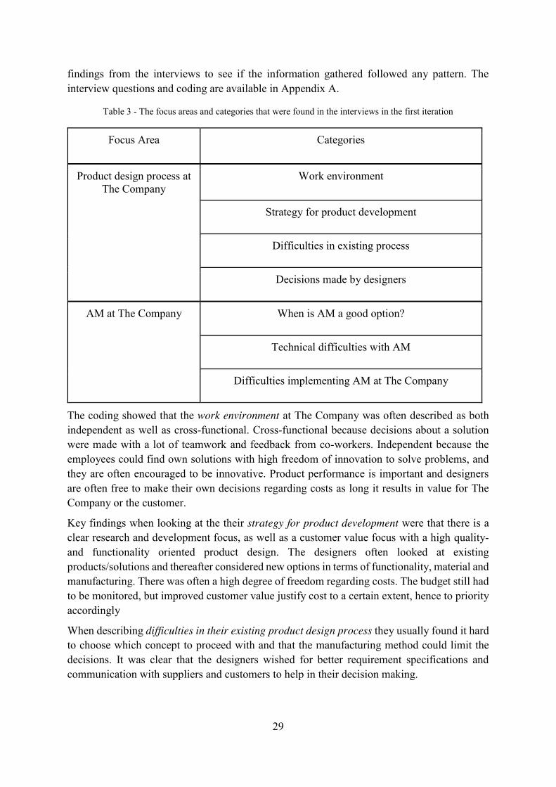
The findings from the interviews were coded according to eight categories, presented in Table 3. The defining phase was done by analysing the interviews from the empathizing phase and defining as well as identifying important information. This was done through coding the key
29
findings from the interviews to see if the information gathered followed any pattern. The interview questions and coding are available in Appendix A.
Table 3 - The focus areas and categories that were found in the interviews in the first iteration
Focus Area Categories
Product design process at The Company
Work environment
Strategy for product development
Difficulties in existing process
Decisions made by designers
AM at The Company When is AM a good option?
Technical difficulties with AM
Difficulties implementing AM at The Company
The coding showed that the work environment at The Company was often described as both independent as well as cross-functional. Cross-functional because decisions about a solution were made with a lot of teamwork and feedback from co-workers. Independent because the employees could find own solutions with high freedom of innovation to solve problems, and they are often encouraged to be innovative. Product performance is important and designers are often free to make their own decisions regarding costs as long it results in value for The Company or the customer.
Key findings when looking at the their strategy for product development were that there is a clear research and development focus, as well as a customer value focus with a high quality- and functionality oriented product design. The designers often looked at existing products/solutions and thereafter considered new options in terms of functionality, material and manufacturing. There was often a high degree of freedom regarding costs. The budget still had to be monitored, but improved customer value justify cost to a certain extent, hence to priority accordingly
When describing difficulties in their existing product design process they usually found it hard to choose which concept to proceed with and that the manufacturing method could limit the decisions. It was clear that the designers wished for better requirement specifications and communication with suppliers and customers to help in their decision making.
30
Regarding the decisions made by designers, they usually made decisions of which concept to move forward with, manufacturing methods, creating drawings and updating these as well as securing the quality and functionality.
When asked about when AM is a good option the interviewees often answered that it was a good option when:
● You had a product with multiple functions ● There are parts that could be integrated ● There is production in smaller volumes ● The product could be made smaller or lighter ● Creating prototypes for testing ● There are large variation in the products ● Shorter lead time is needed ● When there is no conventional manufacturing method that can deliver the function the
designer needs
One designer also mentioned that AM should not be used only because it is fun and new but rather to add value to the product.
The designers had some ideas of when there could be technical difficulties with the AM technology that could limit the usability. Examples of these difficulties were
● The need of post processing ● The settings on the machines differ between production batches ● There are functional limitations on the resulting product ● The material properties had to be better than the ones of conventional parts in order for
them to use it
In addition there were a lack of knowledge of the technologies in general as well as their limitations and potential.
The designers had more input on the difficulties in implementing AM at The Company. Examples of such difficulties were:
● There are no standards when making technical drawings and specifying requirements for AM
● No common way of evaluating the quality of the result ● Lack of design guidelines and methodology ● Nowhere to turn with their questions ● The general conventional way of thinking when it comes to manufacturing ● Skepticism to the quality of the resulting material properties ● The general lack of knowledge which was considered limiting
The difficulty that most designers expressed concern regarding was the skepticism towards the quality of the material in the produced part. The findings from the interviews in iteration one are presented in Table 4. A requirement specification on the methodology was developed based on the knowledge from the interviews and the five aspect of service design. See the requirement specification in Appendix B.
31
Table 4 - Findings from the first iteration
Iteration Findings
1 The Company has an innovative work environment and the designers have high freedom in their decision making, which they liked. Most of the designers wished for better requirement specifications early in the project. The designers have low knowledge of AM.
3.2 Second Iteration - Product Design Process & Stakeholders In the second iteration, the empathize and define steps from the first iteration were performed again, based on the findings from iteration one. Iteration one gave an understanding regarding the freedom in the work environment at The Company, but there was no knowledge about how they use this freedom in practice. The empathizing phase in iteration two focused on understanding the current product design process at The Company and learning who are involved in this process. In the defining phase it was identified where in the product design process information about AM was needed in order to introduce it as a manufacturing method. After this, ideating, prototyping and testing phases followed where a product design process as well as an AM design processes were developed, see Figure 3.3.
Figure 3.3. The steps done in iteration 2
32
Interviews were first made with a focus on understanding which decisions the designers made when developing a product and which people were involved in the process. Seven one hour interviews were made with four of the previously interviewed designers and three new ones with different background, see Table 5.
Table 5 - Designers interviewed in the second iteration
Role at The Company Time at The Company Interviewed in iteration:
Designer 1 Mechanical Engineer 3 years 1
Designer 2 Product Owner 9 years 1
Designer 3 Project Manager 4 years 1
Designer 4 Mechanical Engineer 3 years 1
Designer 5 Product Owner 5 years -
Designer 6 Mechanical Engineer 7 years -
Designer 7 Product Owner 4 years -
Trigger material was used in the interviews as a tool for creating discussion and encouraging creativity. A white paper was given to the designers, where they were asked to draw the product design process of a project. The process should stretch from the time an engineering task was given to them until the project was completed, see Figure 3.4. Meanwhile, they were asked to draw and speak out loud about which choices they made during the process and how they motivated these choices. The interviewer sat quietly throughout the interview and did not ask leading questions.
Figure 3.4 - One of the product design processes made by a designer at The Company
33
In order to fulfill the requirement of “Co-creative - All stakeholders should be included in the service design process” a stakeholder analysis was needed. Therefore, the designers were asked to fill a stakeholder map, see a filled stakeholder map in Figure 3.5. The reason for this was to get a good picture of which people are involved in a product design process at The Company and when they are involved.
Figure 3.5 - All stakeholders involved in the product design process at The Company.
It was important to understand the product design process at The Company in order to develop a design methodology that fit the designer’s way of working today. The product design process, as well as the audio recorded reflections the designers made while drawing these, were analysed and coded to find similarities and differences in the processes, see Appendix C. It was clear that the work environment described in the first interviews was reflected in the product design process. The way of working was free and some of the development processes were individual. The Company has a culture of knowledge-sharing and they are not afraid to ask for help from their colleagues. It is common that the designers create their own documents with “tips and tricks” or methods when approaching a problem. Although the designers had their individual way of working there was a pattern in the processes. The stakeholder identified were included in the product design process as well. The reason of that was to get an understanding of when and why these stakeholders were included, but also to understand where the AM design process should start.
This was followed by the Ideate and Prototype steps where a product design process and a DfAM process were developed. The similarities found from the processes drawn by the designers were concluded and brainstormed to find a product design process, see Appendix D. This resulted in a process with different steps that were verified and tested on two designers that had not been interviewed in this second iteration, see Appendix E. This was done in order to see if these designers felt the steps matched their perception of the development process.
34
With this feedback The Company's product design process was generated into a summarizing seven step process, presented in Figure 3.6.
Figure 3.6 - The identified seven steps of the product design process at The Company.
The DfAM process was also ideated, see Appendix F. This ideation finally resulted in the DfAM process presented in Figure 3.7.
Figure 3.7 - The DfAM design process made based in the findings from iteration two
Important findings from this second iteration, as well as the previous ones from the first iteration, are presented in Table 6.
Table 6 - Findings from the second iteration, as well as the first one
Iteration Findings
1 The Company have an innovative work environment and the designers have high freedom in their decision making. Most of the designers wished for better requirement specifications early in the project. The designers have low knowledge of AM.
2 Identified the designers working methods and developed an AM-process adapted to this. Identified stakeholders and the need for one source of information.
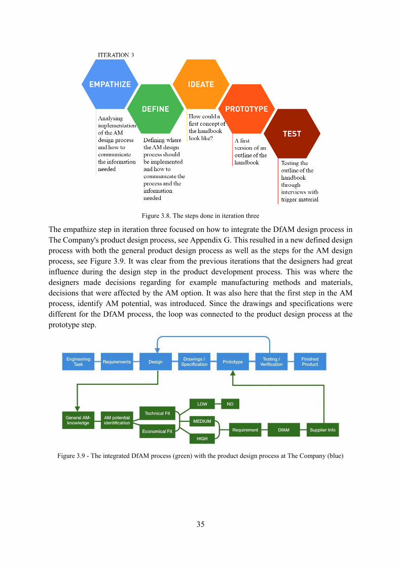
3.3 Third Iteration - AM Design Methodology Concept The purpose of the third iteration was to identify what information the designers needed regarding AM, as well as how to communicate this information. The third iteration started with the empathizing and defining steps, focusing on defining how to communicate the needed information regarding AM. This was followed by an ideation focusing on the visualization of this information. The ideation step resulted in a first prototype of the methodology, a handbook, which was developed and used as trigger material. This trigger material was tested in interviews with the designers with a focus on understanding what information the designers needed to use AM. The steps performed in iteration 3 are visualized in Figure 3.8.
35
Figure 3.8. The steps done in iteration three
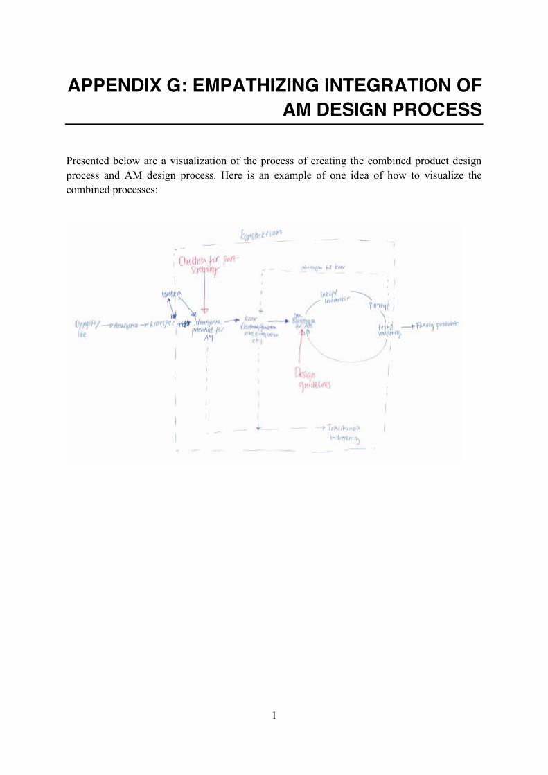
The empathize step in iteration three focused on how to integrate the DfAM design process in The Company's product design process, see Appendix G. This resulted in a new defined design process with both the general product design process as well as the steps for the AM design process, see Figure 3.9. It was clear from the previous iterations that the designers had great influence during the design step in the product development process. This was where the designers made decisions regarding for example manufacturing methods and materials, decisions that were affected by the AM option. It was also here that the first step in the AM process, identify AM potential, was introduced. Since the drawings and specifications were different for the DfAM process, the loop was connected to the product design process at the prototype step.
Figure 3.9 - The integrated DfAM process (green) with the product design process at The Company (blue)
36
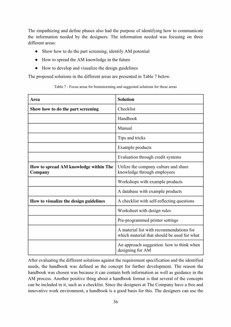
The empathizing and define phases also had the purpose of identifying how to communicate the information needed by the designers. The information needed was focusing on three different areas:
● Show how to do the part screening, identify AM potential
● How to spread the AM knowledge in the future
● How to develop and visualize the design guidelines
The proposed solutions in the different areas are presented in Table 7 below.
Table 7 - Focus areas for brainstorming and suggested solutions for these areas
Area Solution
Show how to do the part screening Checklist
Handbook
Manual
Tips and tricks
Example products
Evaluation through credit systems
How to spread AM knowledge within The Company
Utilize the company culture and share knowledge through employees
Workshops with example products
A database with example products
How to visualize the design guidelines A checklist with self-reflecting questions
Worksheet with design rules
Pre-programmed printer settings
A material list with recommendations for which material that should be used for what
An approach suggestion: how to think when designing for AM
After evaluating the different solutions against the requirement specification and the identified needs, the handbook was defined as the concept for further development. The reason the handbook was chosen was because it can contain both information as well as guidance in the AM process. Another positive thing about a handbook format is that several of the concepts can be included in it, such as a checklist. Since the designers at The Company have a free and innovative work environment, a handbook is a good basis for this. The designers can use the
37
information they are interested in and learn more about new areas. The decision was also based on the information from the interviews in the first iteration. The designers expressed a need for one source of information that they could turn to when they had questions regarding AM technologies or the DfAM process. The idea was that an AM handbook could be this source of information, providing guidance and understanding for each of the steps in the DfAM process.
Thereafter an ideation followed to form the outline of the first Additive Manufacturing Handbook. A handbook prototype was developed as trigger material to be tested and further analysed in interviews with the designers. The purpose of the testing was to learn what information the designers wanted in each step of the AM design process.
The interviews were conducted with six designers, four that had been met in the previous iterations and two new ones, see Table 8.
Table 8 - Designers interviewed in the thirds iteration
Role at The Company Time at The Company Interviewed in iteration:
Designer 1 Mechanical Engineer 3 years 1
Designer 2 Product Owner 9 years 1 & 2
Designer 3 Mechanical Engineer 3 years 1 & 2
Designer 4 Mechanical Engineer 7 years 2
Designer 5 Mechanical Engineer 5 months -
Designer 6 Mechanical Design Engineer
1 year -
When the designers were given the trigger material they were first asked to describe their thoughts about the idea of a printed handbook and how they generally prefer to receive information. Then they opened the handbook, one spread at the time. Each spread had a headline to give a clue of what the content would be, the headlines were:
● Content ● Why AM? ● Think AM/Considerations ● AM Design Freedom ● Timeline ● Estimated Printing Time ● Technologies ● Comparison ● Technical Fit / Economic Fit ● Design Guidelines ● Step File and Quality Requirements
38
The designers were asked to write down what they would like the handbook to contain on post-it’s and put them on the page. Some post-it’s were already attached on one spread, as an example to encourage and help the designers get started, see Figure 3.10. These post-it’s were based on the information from the designers in the previous interviews.
Figure 3.10 - The example spread with post-it’s from the trigger material handbook
They went through the handbook outline, gave feedback on the wanted content for each of the headlines and wrote down their thoughts on post-its. A short discussion on their overall impression was done at the end of the session. Afterwards the post-it’s were collected for coding and the trigger material-handbook could be used on the next designer. The post-it’s were then coded according to the headlines they were posted on, see Table 9.
39
Table 9 - Key Findings from the interviews with trigger material in the third iteration
Section Question asked Key Findings
Front Page How do you want to receive information
No place to find information today, a handbook seems like a good format.
Interactive PDF (with clickable links and headlines)that could be printed if wanted.
Information through illustrations, examples, bulleted lists. A lot information is fine with a
good table of content.
Content What do you wish to find in this handbook?
Information about technologies, materials, price vs volume, design guide, material
properties, links and contacts
Why AM? What do you expect to read on this page?
Advantages for The Company, benefits with AM and design freedoms, properties, lead-
time, costs
Think AM/Considerations
What do you expect to read on this page?
No limitations, function before manufacturing method, example
Am Design Freedom What do you expect to read on this page?
Keep some post processing, prototypes but perhaps also end-use products, Value through
short lead times, worth higher price
Timeline What do you expect to read on this page?
Is it really a line, iterative? Part Screening hard but important.
Estimated Printing Time
What do you expect to read on this page?
Don’t trust these kind of estimations, too estimated - not useful
Technologies What do you expect to read on this page?
Want examples. Not sure what information they want because of lack of knowledge. Orientation and materials would be good.
Comparison What do you expect to read on this page?
Mechanical properties and accuracies. Pictures and charts. Prototype or production?
Technical / Economic Fit
What do you expect to read on this page?
Don’t understand what this mean. Want clear examples of the potential with AM. Value isn’t
economical at The Company.
Design Guidelines What do you expect to read on this page?
Limitations with technologies and how to design accordingly
Step File and Quality
Requirements
What do you expect to read on this page?
This is a really complex question. Someone at The Company has to decide a method or
standard for this.
Important findings from this session is that the designers prefer to see a lot of illustrations and examples rather than reading text. They want to know more about the technologies as well as when to use AM. Another finding is that the Technical/Economical Fit section is a bit unclear,
40
especially since the economical aspect is not that important as a value factor for The Company. Other aspects are more important for creating value, for example technical performance or customer satisfaction. It was mentioned that the handbook should help the designers motivate their choices. According to the designers there is a risk when using AM and therefore they have to define what value it adds to the customer and the technology.
It became clear that a PDF was the format of choice and that the reaction to the overall layout was positive. All designers looked forward to see the result and thought that this was something that could truly help them in their work. With their feedback a first version of the handbook was developed. Findings from the third iteration, as well as the findings from previous iterations, can be found in Table 10.
Table 10 - Findings from the third iteration, as well as the previous ones
Iteration Findings
1 The Company have an innovative work environment and the designers have high freedom in their decision making. Most of the designers wished for better requirement specifications early in the project. The designers have low knowledge of AM.
2 Identified the designers working methods and developed an AM-process adapted to this. Identified stakeholders and the need for a source of information.
3 Wanted content in the handbook: examples, a lot of information about the technologies, economic part is not as important as other value aspects, the handbook should be in an interactive PDF:format.
3.4 Fourth Iteration - AM Handbook Based on the information from iteration three, a first draft of the handbook with illustrations and information regarding the AM process was designed. The purpose of Iteration 4 was to get more feedback on the concept and it was performed through two steps, prototype and test, see Figure 3.11.
Figure 3.11 - The steps done in iteration 4
41
Due to confidentiality reasons the handbook cannot be shown in this report. In this chapter it will instead be described with words. The created handbook began with a general overview of AM and a description of why the technologies could create value for The Company. After that, the six-step process presented in Figure 3.12 followed. These steps were based on the first DfAM process developed in iteration 2.
Figure 3.12. The developed steps of the design for AM methodology
The challenge was to identify where in the DfAM process the designers should make a decision regarding using AM as a manufacturing and how this decision would be made. The decision was divided into four steps:
● Identification of AM Potential ● Part Screening ● Specify Requirement ● Design for AM
Two more steps, Prototype & Test and Send to Supplier, are not a part of this study but needs to be taken into account when manufacturing a product or prototype with AM. The first step, identification of AM Potential contained information regarding when it could be beneficial for The Company to use AM and which benefits they could achieve by using AM as manufacturing method. Part Screening explained the importance of knowing when and why to use AM for the designer. Specify Requirements briefly touched the subject of the importance of specifying the purpose and needs of the product or component before the design process. The fourth step, Design for AM, gave an introduction to the four chosen technologies (SLS, SLM, MJF and BJ) with the purpose of helping the designer choosing the correct one for the purpose. It contained information about pros and cons with each technology, a comparison between them as well as guideline for the AM design considerations
The chapters in the handbook were based on the identified steps in the process. Each chapter have information and illustrations where the reader could learn about the subject. The chapters in the handbook also had an associated appendix in the form of checklists or questions. The purpose of these appendices was to make the designers reflect on their decisions and document them. They could also be used in the communications with the stakeholders from different steps in the product design process such as suppliers or project managers. When implementing the
42
methodology the appendices could guide the designers without having to read the full handbook every time.
The handbook draft was tested through a questionnaire that was sent out to 13 designers at The Company. The purpose of the questionnaire was to let the designers read the handbook and evaluate the concept. The questions asked were about the content in each chapter, the illustrations and the ability to use the handbook, see Appendix H. The overall reaction was good but the handbook needed some modifications such as:
● The illustrations needed to be updated and the designers wished for less text in the handbook
● The technologies explained in the Design for AM- step was presented in the order: SLS, SLM, MJF and BJ. Instead it should be presented according to the material used, with the polymer technologies first and then metal technologies: SLS, MJF, SLM and BJ
● The handbook could be made easier to follow by adding more examples of products that have been successfully printed with AM, as well as examples of how products that are printed with the various technologies differ visually
● The purpose of the appendices could be made clearer through adding examples of how to use them.
Findings from the fourth iteration, with findings from previous iterations, can be found in Table 11.
Table 11 - Findings from the fourth iteration, as well as the previous ones
Iteration Findings
1 The Company have an innovative work environment and the designers have high freedom in their decision making. Most of the designers wished for better requirement specifications early in the project. The designers have low knowledge of AM.
2 Identified the designers working methods and developed an AM-process adapted to this. Identified stakeholders and the need for a source of information.
3 Wanted content in the handbook: examples, a lot of information about the technologies, economic part is not as important as other value aspects, the handbook should be in an interactive PDF:format.
4 Designers want examples of products printed with the different technologies, examples of products that have been successfully printed with AM, examples of how to use the appendices, update of the illustrations, less text, change the order of the process (specify requirements should come before the part screening) and the technologies. More information about material restrictions and orientation in the different technologies.
43
3.5 Fifth Iteration – Case Study The fifth iteration was also carried out in two steps, prototype and test, see Figure 3.13. The purpose of the fifth iteration was to create a new handbook based on the feedback from iteration four and test it through a case study.
Figure 3.13 - The steps done in iteration 5
A final handbook was made with some changes made based on the questionnaire feedback from iteration four. Thereafter a case study was performed where a part from The Company’s product range was chosen and used to evaluate the final handbook. This part was chosen as it was identified with high AM potential by one of the designers that had been interviewed earlier in the thesis. It had high general AM potential because of the current expensive and difficult conventional manufacturing process and the ability to combine multiple components into one. The part was an end use part and the requirement specified were high air tightness as well as flatness requirements on some surfaces. The first step of the AM design process, Identify AM potential, was performed by one of the designers at The Company, as explained earlier. The other steps were done by the authors of this thesis in collaboration with designers. The designers helped with answering questions as well as the redesign of the part in CAD.
After testing the methodology with the case study of the component, further areas of improvement emerged. The first thing that was realized was that the steps Specified Requirement and Part Screening in the methodology needed to change place. It is relevant to specify the requirements of a product before making a decision regarding whether AM is a good option. Another area of improvement was that the choice of technology needed to be made clearer. Therefore another step had to be added for this purpose. This choice must be done before the product is designed for AM because all the technologies have different design guidelines. Some of the general questions used in the appendix for the first step - identify AM potential, turned out to be irrelevant, so they were removed or replaced with more relevant questions.
44
Findings from the fifth iteration, with findings from previous iterations, can be found in Table 12.
Table 12 - Findings from the fifth iteration, as well as the previous ones
Iteration Findings
1 The Company have an innovative work environment and the designers have high freedom in their decision making. Most of the designers wished for better requirement specifications early in the project. The designers have low knowledge of AM.
2 Identified the designers working methods and developed an AM-process adapted to this. Identified stakeholders and the need for a source of information.
3 Wanted content in the handbook: examples, a lot of information about the technologies, economic part is not as important as other value aspects, the handbook should be in an interactive PDF:format.
4 Designers want examples of products printed with the different technologies, examples of products that have been successfully printed with AM, examples of how to use the appendices, update of the illustrations, less text, change the order of the process (specify requirements should come before the part screening) and the technologies. More information about material restrictions and orientation in the different technologies.
5 Some changes needed to be done in the methodology in order to be able to use it in a good way with a product. These changes were: an addition of a step in the process called “choice of technology”, change in order of the step 2 and 1 and changes in appendix for step one – identify AM potential.
45
4 RESULTS In this chapter the resulting handbook, made through the processes and methods presented in previous chapters, will be presented.
4.1 AM Handbook The result of this thesis is an AM handbook with information regarding AM and a proposed methodology for choosing when and why to use AM as a manufacturing method. The information in the handbook is developed to fit the needs of the designers and products at The Company. The methodology presented follows a five step process shown in Figure 4.1. Step 6 and 7 is not included in the methodology, see chapter 1.4 Delimitation, but is still represented since this is part of the total process of using AM as a manufacturing method. Due to confidentiality reasons the handbook cannot be shown in this report. In this chapter it will instead be described with words in combination with illustrations from the handbook.
Figure 4.1. The design for AM process, illustration made for the handbook by thesis authors
The design methodology include the following five steps:
1. Identify the general AM potential by using the information presented and questions asked in the handbook. The general potential is based on the production volume, the customization and complexity of the component. The goal is to find a product or component with potential, for further evaluation.
2. Specify the requirement of chosen product or component. The purpose of this step is to identify the most critical requirement of the product or component like surface finish, tolerance or material restrictions.
3. Perform a part screening of the chosen product or component in order to evaluate if the most critical requirements specified in step 2 can be fulfilled. This step gives the product a grade of low, medium or high potential to successfully be manufactured with AM. This is done by looking at size, material, quality requirements and value creation.
4. Choose the technology best suited to meet the requirements of your product. The four technologies give different results depending on what you are looking for. For example, BJ is better for small, detailed metal parts than SLM.
5. Use the design guidelines template to design the product or component for AM. When designing for AM, one needs to consider aspects such as hole size, wall thickness, overhangs, pin diameter etc.
46
4.1.1 Step one - Identify AM potential Identifying AM potential is the first step in the decision making regarding AM as a good manufacturing alternative. The purpose of this step is to identify the general AM potential early in the project, before the manufacturing method is chosen. Designers should be able to look at the product and through a quick and easy identification process learn if the component or product have potential for AM or not. The first thing to look at when evaluating AM potential is production volume, complexity and customization, see Figure 4.2. As mentioned in chapter 2.1.3 Potential use of AM, AM technologies are generally not the best option for mass-producing products and is therefore an appropriate manufacturing method in low volume productions. AM production should focus on products with high customization or complexity, or a combination of both. The Company could also use AM for prototyping parts that should later be manufactured with conventional methods in high volumes, for example casting, molding or machining. AM is a fast way of producing prototypes, which can save time in the product development process.
Figure 4.2 - The three general parameters when investigate AM potential; production volume, complexity and customization. Illustration made for the handbook by thesis authors
In addition to these three parameters, five aspects that should be taken into account have been identified, see Figure 4.3. These five aspects were identified in order to help the designers define how AM can create value for The Company as well as to show how AM can be utilized in order to gain as much benefits as possible. If the product does not create value through implementing at least one of these five aspects, then perhaps it should not be manufactured with AM.
47
Figure 4.3 - The five AM aspects that should be utilized to add value for The Company. Illustration made for the handbook by thesis authors
The purpose with this first step is to generate a discussion through which the designers can decide if AM is a suitable manufacturing method for the chosen product or component. In the handbook there is an appendix connected to this first step, a checklist of questions where the answer yes/no/maybe are to be filled in, see Appendix I. A checklist with at least one “yes” means that the product has an AM potential and that this should be investigated further.
4.1.2 Step two - Specify requirement
Step two in the decision making is to specify requirements. This is a result of the designers wish for a more detailed requirement specification in the beginning of the projects. Is also used as a foundation for the next steps, part screening, choice of technology and design for AM. Sometimes with AM not all requirements regarding for example accuracy, surface finish or geometry can be achieved. Therefore it can be advantageous to focus on the most important requirement. Then it is important to identify which requirements that cannot be compromised and keep this in mind when deciding if the product can be printed, choosing technology and designing for AM. The questions described below are part of the corresponding appendix for this step and should be answered before continuing to the next step in the process.
1. What’s the use of the part?
The first thing to specify is whether the product should be produced in purpose of being an end-use product or a prototype. An end use product and a prototype can have different requirements. A visual prototype for example have high requirements on surface finish while an end use product might have high tolerance requirements.
2. What’s the goal with the part? What do you want to achieve?
The designers should look at the five AM aspects and identifying how they want to optimize the part or component.
48
3. What requirements does the part need to achieve the goal?
Identify which requirements that is most important to achieve the goal defined in question. A lightweight component might not have as high surface finish requirements as a component or product with complex internal structures.
4.1.3 Step three - Part screening The third step in the decision making is the final decision about if the product should be printed and if it can be printed. In this step it is shown how the size, material and geometry requirements could be analysed in order to decide if the product can be printed. The value added decides if the product should be printed. If AM does not provide any added value, then it should not be manufactured with AM. The questions in the corresponding appendix helps the designers analyse if the product can be printed, if it fits in the printer chamber, if there is a suitable material available as well as analyse if the requirements specified in step two can be fulfilled, see Appendix J. It also helps them reflect on whether the product should be printed, if there is added value. The purpose of the appendix is to provide the designer with an indication if the product has high, medium or low potential for AM.
4.1.4 Step four - Choice of technology
All technologies presented in this methodology handbook have limitations and possibilities making them suitable for different situations. The designer needs to be aware of these in order to make the right decision. The purpose of this chapter is to help the designer choose a technology based on the requirements specified in step two by providing information about the technologies restrictions and possibilities. Each technology is presented with information and illustrations regarding how the manufacturing method works, see Figure 4.4.
A B
C D
Figure 4.4 - The illustrations in the handbook explaining the four technologies: A: SLM, B: SLS, C: MJF, D: BJ. Illustration made for the handbook by thesis authors
49
They are also presented with pros and cons as well as important general information. A diagram with a comparison between the technologies is also presented to help designers to make their decision. The diagram from the handbook is shown in Figure 4.5 and the aspects that are represented are described both in the handbook as well as below:
● Production volume Refers to the batch volume, how many parts are suitable to manufacture? This depends on for example continuity, price and ability to produce many parts at once
● Part Volume How large is the possible part size? Build chamber size and technology limitations decides this.
● Complexity How high is the degree of geometrical complexity? This depends on the powder behavior and need for support structure.
● Cost What is the cost? This is decided by for example the material cost, material used and post processing.
● Material Requirements How good are the mechanical properties? This depends on the quality of the final material after sintering/melting/infiltration.
● Lead Time How long does it take to manufacture a part with the technology? The lead time is affected by pre-heating, post processing as well as the manufacturing time
● Accuracy How good is the surface and detail accuracy before post-processing? The accuracy of the part depends on the technology but also orientation and material.
● Design freedom How high is the degree of design freedom? Things like support material and limits in the design decides what is possible to manufacture and not.
50
Figure 4.5 - Comparison of the four technologies. Illustration made for the handbook by thesis authors
4.1.5 Step five - Design for AM The 5th step in this process is the design guidelines of AM products. The guidelines are divided according to the different technologies and present the design aspects that should be taken into consideration when a product is constructed. The appendix consists of a number of self-reflection questions that the designers should answer before contacting the supplier, see Appendix K.
51
5 DISCUSSION AND FUTURE WORK In this chapter the reader will learn about the authors’ conclusions from the thesis as well as a discussion regarding important aspects of the thesis. A recommendation of future work for The Company will also be given.
5.1 Discussion The purpose of this thesis was to develop a methodology that could add AM to the designers manufacturing toolbox. This has been fulfilled through usage of iterative methods and continuous work with the designers. It has shown that a dynamic task is best solved through working with a dynamic methods. In the following sections a discussion regarding the methods used and the final result will be discussed.
5.1.1 Methods The service design thinking approach does not fit all development projects, but it has been good in this thesis. The reason why it suited this thesis was because the main focus was on developing a methodology that was adapted to the needs of the designers, which is the key aspect in service design thinking. The developed methodology should also be implemented in a big organization with an already existing culture. This makes it crucial to understand the user and The Company before developing the methodology, which is possible when using a service design thinking approach. Through iteratively testing ideas on the user the results came closer and closer to a useful methodology.
All methods used in the thesis have had a clear purpose, which is important when choosing a method. The stakeholder analysis gave useful insights and put the product design process in perspective to the organization at The Company. It was also useful when the AM methodology was linked to the existing product design process. The questionnaire used could have been replaced with interviews made with the designers at The Company. It showed that it is difficult to obtain useful information from a questionnaire and that the response rate was low. The choice to test the methodology with a case study was good since it provided insight into how the methodology works in practice.
What was limiting with the methods used to develop the design methodology was that only 13 designers were interviewed. The results from the different interviews were coherent and therefore a true answer is believed to have be found. There is a risk however that the interviewees created a too homogenous group. All respondents were men and most were in the same age with similar backgrounds and a generally low knowledge regarding AM. The risk when developing a service that is designed for a homogenous group is that the result will not be adapted for the general user. By including more designers with different backgrounds within The Company this risk could have been avoided. Finding interviewees with different background was not easy and the general designer at The Company is believed to be relatively homogenous. Therefore the risk that the handbook would not be suited for the majority of the designers is believed to be small.
52
It would have been desirable if the designers at The Company did perform the case study in order to evaluate the methodology. Now, the first steps in the DfAM process were made with the help of a designer, but the remaining steps were performed by the thesis authors. This may have affected the outcome of the case study. The reason for this was because a product design process at The Company can sometimes go on for several months, which didn't fit within the time frame of this project. The method can be implemented in future product design projects in the Company, and thus evaluated. The option chosen made it possible to evaluate the first steps of the method, which was considered the best solution.
5.1.2 The Result In this thesis, selected information regarding AM, adapted to the designers at The Company, have been presented. Since AM is a continuously growing area, there is an incredible amount of information to gather from books, articles and websites. Early in the thesis, a choice was made between examining the subject broadly or narrowly. It was decided to investigate the subject relatively broadly and focus on four different techniques. In hindsight, it might have been good to focus on one type of technology because it would have given a more detailed methodology. On the other hand, The Company has a need to provide information of several technologies since the products to be manufactured have different needs.
If unlimited information regarding AM, with all technologies and opportunities, could be included it would of course be preferable. Finding the perfect balance between providing all information and overwhelming the reader can be difficult. This handbook gives a good foundation to make decisions regarding AM. Since The Company today has limited experience of prototyping via AM, and less of production parts, this is believed to be a good start. For the handbook to keep on being useful to the designers it has to be updated continuously. AM technologies are constantly developing and improving, something that the handbook has to take into consideration. It is therefore important that the information in the handbook is general but at the same time accurate enough to be useful in the future as well. The numbers and specifications in the handbook are clearly structured. This is done purposely so that they can easily be updated if such changes occur. In the handbook, links to interesting websites and databases are included. Hopefully these websites will continuously update the information and the reader can therefore easily find information that is up-to-date.
It is believed that this handbook is only the beginning of The Company’s work towards a work environment where AM is a natural part of the manufacturing tool-box. The main purpose of the handbook should therefore be to create an interest and curiosity regarding the AM technologies. Through opening the designer’s eyes to the possibilities instead of the constraints they will hopefully gain an interest that will result in them keeping themselves updated in the future, without the handbook. Hopefully this will also result in The Company investing in further activities and actions that will promote AM as a manufacturing method.
5.2 Future Work As mentioned in this report, AM is an area in continuous development, which means that the methodology needs constant updating to remain relevant. DfAM is only a part of the AM-area
53
and needs to be supplemented with different knowledge as well. This thesis has shown that there is a general lack of knowledge regarding AM in The Company. The first step after implementing this design methodology handbook is to investigate how the organization and business is affected when implementing AM. They should also decide the nature of the relationships with chosen suppliers and create methods for sharing information and designs. Today they have a special group focusing on the area but the members of this group all have other responsibilities. If they feel that this AM group is satisfying enough for now, another thing they can do is to continue having thesis students looking into other aspects of AM. Thesis works are a good way of thoroughly research an area of interest and to get input from someone that is not yet influenced by the way The Company works today. As part of The Company’s future work there are three areas that are believed to be of special interest, these areas are:
● Drawings and specifications ● Material and verification ● Value Creation
Drawings and specifications is an important aspect of the future of AM, for all businesses. The consideration of sharing and specifying PMI has to be solved. One way could be combining 2D- and 3D models. A 3D model has to be shared for an AM part to be manufactured but simplified 2D drawings could be used to specify things such as post processing and orientation.
The second aspect of material and verification is also important for the future of AM. Material options within AM are constantly growing but how the materials are affected by the manufacturing method and how to verify material properties still needs more research. The two steps in the developed AM design process that have not been included in this thesis, step six: prototype and test as well as step seven: send to supplier, needs to be included in the process in the future. By looking into the first two areas of interest these last two steps could be investigated and the methodology further developed.
The last area of interest is the value creation. Something that The Company has to review is what impact the handbook has on their business. Value creation is something that is very important to The Company and the handbooks impact on this area has to be verified. When reviewing the implementation of the handbook new areas of interest may occur that could be included in the methodology.
The company should utilize their culture of design freedom and high communication to learn from each other and create new discussions to keep the AM movement going forward.
54
55
7 REFERENCES Literature: Bourgue, O., Panarotto, M. and Isaksson, O. (2018) Impact on design when introducing additive manufacturing in space applications. International design conference- design 2018. p 997- 1008.
Conner, Brett P., Guha P. Manogharan, Ashley N. Martof, Lauren M. Rodomsky, Caitlyn M. Rodomsky, Dakesha C. Jordan and James W. Limperos. 2014. Making sense of 3-D printing: Creating a map of additive manufacturing products and services. Additive manufacturing. 1-4: p 64-76
Dosser, L., Hartke, K., Jacobson, R., Payne, S. 2017. Chapter 24: Additive Manufacturing Technology Review: From Prototyping To Production. Additive manufacturing handbook - Product Development for the Defense Industry. Edited by: Adedeji B. Badiru, Vhance V. Valencia and David Liu. Florida: CRC press
Durakovic, B. 2018. Design for Additive Manufacturing: Benefits, Trends and Challenges. Periodicals of Engineering and Natural Sciences. 6(2), p 183-184
Gibson, I., Rosen, D.W. and Stucker, B. 2010. Additive manufacturing technologies, Rapid Prototyping to Direct Digital Manufacturing. Springer, New York, NY, London.
Gibson, I., Rosen, D., Stucker, B. 2015. Additive Manufacturing Technologies, 3D Printing, Rapid Prototyping, and Direct Digital Manufacturing. Second Edition, Springer New York Heidelberg Dordrecht London
Kumke, M., Watschke, H., Vietor, T. 2017. Chapter 12: A new methodological framework for design for additive manufacturing. Additive manufacturing handbook - Product Development for the Defense Industry. Edited by: Adedeji B. Badiru, Vhance V. Valencia and David Liu. Florida: CRC press
Lindemann, C., Jahnke, U., Moi, M. and Koch, R. 2012. Analyzing product lifecycle costs for a better understanding of cost drivers. 23th Annual International Solid Freeform Fabrication Symposium - An Additive Manufacturing Conference, Austin, TX, 6-8 August.
Lindemann, C, Reiher, T, Jahnke, U and Koch, R. 2015. Towards a sustainable and economic selection of part candidates for additive manufacturing. Rapid Prototyping Journal. 21(2), p 216-227
Mellor, S., Hao, L. and Zhang, D. 2013. Additive manufacturing: A framework for implementation. International Journal of Production Economics.
Milewski, J O. 2017. From fundamental technology to rocket nozzles, medical implants and custom jewelry. Springer international publishing p 205-207.
Milton, A. 2013. Research Methods for Product Design. Laurence King Publishing
Paluzie Noe, A. Data preparation. AMEXCI. February 2019.
56
Rosen D.W. 2014. Research supporting principles for design for additive manufacturing. Virtual and Physical Prototyping, Vol 9 No 4, p 225-232
Stickdorn, M. and Schneider, J. 2014. This is service design thinking. Bis Publishers B.v.
Wang, L. and Ju, Y. 2017. State-of-the-art of 3D printing technology of cementitious material - An emerging technique for construction. Science China Technological Sciences.
Wang, Y., Blache, R. and Xu, X. 2017. Selection of Additive Manufacturing Processes. Rapid Prototyping Journal 23(2) p 434-447. Ackland, New Zealand: Department of Mechanical Engineering, University of Auckland.
Witherell, P., Herron, J. and Ameta, G. 2016. Towards Annotations and Product Definitions for Additive Manufacturing. Procedia CIRP. Volume 43. Pages 339-344
Wohlers, T. and Gornet, T. 2014. History of additive manufacturing. Wohlers Report 2014. WOHLERS ASSOCIATES, INC.
Online: 3D Hubs. Knowledge Base - manufacturing processes explained. [online] Available at: <https://www.3dhubs.com/knowledge-base/> [Accessed 23 April 2019].
Cambridge dictionary. [online] Available at: <https://dictionary.cambridge.org/dictionary/english/iteration> [Accessed 6 May 2019].
Granfelt Laurén, S. and Borell, S. 2018. Trigger, Concept and Story - the power of visuals and storytelling. MF2038 Service Design. [online via internal VLE] KTH Available at: <https://kth.instructure.com/courses/6634/files/folder/Lectures> [Accessed 25 April 2019].
Plattner, H. An Introduction to Design Thinking PROCESS GUIDE. Institute of Design at Stanford. [PDF] Available at: <https://dschool-old.stanford.edu/sandbox/groups/designresources/wiki/36873/attachments/74b3d/ModeGuideBOOTCAMP2010L.pdf> [Accessed 16 April 2019]
Recrosio, E. 2017. Optimize your 3D Printed Parts with Lattice Structures. Sculpteo [online] Available at: <https://www.sculpteo.com/blog/2017/05/24/optimize-your-3d-printed-parts-with-lattice-structures/> [Accessed 24 January 2019].
Sculpteo. 2016. What are the Innovations to Come in 3D Printing?. [online] Available at: <https://www.sculpteo.com/blog/2016/11/09/what-are-the-innovations-to-come-in-3d-printing/> [Accessed 30 April 2019].
Sculpteo. 2018. The state of 3D printing, Version 4. [pdf] Available at: <https://www.sculpteo.com/media/ebook/State_of_3DP_2018.pdf> [Accessed 30 April 2019].
Senvol. Senvol Database - Machine Search & Material Search. [online] Available at: <http://senvol.com/> [Accessed 23 April 2019].
57
8 FIGURE REFERENCES Literature: Conner, Brett P., Guha P. Manogharan, Ashley N. Martof, Lauren M. Rodomsky, Caitlyn M. Rodomsky, Dakesha C. Jordan and James W. Limperos. 2014. Making sense of 3-D printing: Creating a map of additive manufacturing products and services. Additive manufacturing. 1-4: p 64-76
Paluzie Noe, A. Data preparation. AMEXCI. February 2019.
Wang, L. and Ju, Y. 2017. State-of-the-art of 3D printing technology of cementitious material - An emerging technique for construction. Science China Technological Sciences.
Online: 3D Hubs. Knowledge Base - manufacturing processes explained. [online] Available at: <https://www.3dhubs.com/knowledge-base/> [Accessed 23 April 2019]
3dnatives. [online] Available at: <https://www.3dnatives.com/en/3d-printing-vs-cnc-160320184/> [Accessed 2 May 2019]
Formlabs. [online] Available at: <https://formlabs.com/blog/what-is-selective-laser-sintering/> [Accessed 29 April 2019]
gkn powder metallurgy. [online] Available at: <https://www.gknpm.com/en/our-businesses/gkn-additive/am-in-action/redesigning-hydraulic-blocks-in-additive-manufacturing/> [Accessed 29 April 2019]
Materdome3D. [online] Available at: <https://materdome3d.com/about> [Accessed 8 May 2019].
Noizear. [online] Available at: <https://noizear.com/crystallon-lattice-structures-in-rhino-and-grasshopper/> [Accessed 29 April 2019]
Plattner, H. An Introduction to Design Thinking PROCESS GUIDE. Institute of Design at Stanford. [PDF] Available at: <https://dschool-old.stanford.edu/sandbox/groups/designresources/wiki/36873/attachments/74b3d/ModeGuideBOOTCAMP2010L.pdf> [Accessed 16 April 2019]
Popularmechanics. [online] Available at: <https://www.popularmechanics.com/technology/design/a20301/ge-opened-a-factory-for-3d-printing-metal/> [Accessed 29 April 2019]
Prusa3D. [online] Available at: <https://www.prusa3d.com/warping/> [Accessed 29 April 2019]
Sculpteo. 2018. The state of 3D printing, Version 4. [pdf] Available at: <https://www.sculpteo.com/media/ebook/State_of_3DP_2018.pdf> [Accessed 20 April 2019].
58
Solidworks. [online] Available at: <https://blogs.solidworks.com/solidworksblog/2017/06/introduction-designing-metal-3d-printing.html> [Accessed 29 April 2019]
The manufacturer. [online] Available at: <https://www.themanufacturer.com/articles/moving-from-3d-printing-to-additive-manufacturing/> [Accessed 29 April 2019]
The Technology House. [online] Available at: <https://www.tth.com/3d-printing/multi-jet-fusion-mjf/> [Accessed 15 May 2019]
Zedax. [online] Available at: <https://www.zedax.ch/index.php/fr/impression-3d/mat%C3%A9riaux/absplus-pour-fdm.html> [Accessed 29 April 2019]
1
APPENDIX A: INTERVIEW QUESTIONS AND MAPPING - ITERATION 1
Interview questions Everything that is said on this interview will be anonymous and the information will form the foundation of a master's thesis at KTH. The audio file will not be saved after the end of the thesis, it will be used as a backup during the thesis time. (VT 2019) Warm up
x What's your name? x How old are you? x What did you study? x When did you graduate from school? x How long have you been working at The Company? x What is your position at the company? x Which group do you work in? x Which kind of product do you work with?
Work today:
x What is the best about your work? x What is difficult with your work? x Describe a typical workday. x What programs/software do you use? x Please explain, to the extent of your knowledge, what your company's design process
look today? o Do you see any advantages/disadvantages with the company’s current design
process? What? o How does this process affect the work that you do? o Is there a methodology to follow? o How do you know what to do and when? o How is your work tasks decided?
x Have you heard of Design for manufacturing or design for assembly? o If yes, how is this integrated in your work?
x Do you work with customer value? o How? o What is the most difficult part about creating customer value?
x Do you work with product optimization? o How? o What is the most difficult part of product optimisation?
x How do you tackle problems that appear in your everyday work? x How do you verify product requirements?
Stakeholders
x Which departments in the company do you work closest to? x How does your communication look like? x How often do you interact with different departments?
2
Knowledge about AM x Have you heard of additive manufacturing?
o If yes, what do you know about it? o if no, we will explain.
x Do you think that a implementation of AM will affect your work? o How?
x Do you know what FEM analysis is?
Attitude to learning new things
x How do you feel about learning new things at your work? x From 1-5, how would you rank yourself when it comes to software knowledge?
Coding
The interviews were summarized on post-its and then coded to find categories of interest. The categories from the coding were the following: Complexity Quality requirements AM Prototyping Lack of Knowledge/ Prejudice Creative/Freedom Cross Functional Customer Oriented Lack of Process Lack of Time
1
APPENDIX B: REQUIREMENT SPECIFICATION Requirement Specification: The methodology should:
x Be adapted to the designers needs at The Company x Provide a foundation for decision-making regarding part screening (if the part have
potential for AM or not) x Be a first version of a design process for AM, it should be possible to update and
develop the methodology x Include design guidelines for AM x Make AM a possible manufacturing method for the designers at The Company x Be implementable at The Company today, it should fit the currently used product design
processes x Be easy to understand regardless of previous AM knowledge x Encourage curiosity towards AM and increase interest in the area x Provide general knowledge of the technologies as well as AM potential and
considerations x Should include all stakeholders x Involve both prototyping as end use products x Be based on scientific fact
The methodology wish to:
x Be as few steps as possible x Involve material restrictions x Involve orientation on the product x Work as a blueprint for when and why to use AM
2
1
APPENDIX C: CODING OF TRIGGER MATERIAL - ITERATION 2
The product design processes drawn were summarized on post-its and then coded according to the following categories:
Process at The Company
Work Environment - How is the product design process affected by the work environment?
Strategy - What strategics does the designer take into consideration during the product design process?
Difficulties with way of working - When and what difficulties are there in the product design process?
Decision - When does the designers make decisions in the product design process?
AM at The Company
When AM? - When in the product design process should AM be introduced?
Difficulties with AM technology - Where in the product development process could there be difficulties due to AM constraints?
Difficulties implementing AM - Where in the product development process could there be difficulties in implementing AM?
2
1
APPENDIX D: CREATING THE PRODUCT DESIGN PROCESS
Brainstorming of the product design process performed by the authors of this thesis. In this brainstorming there was a focus on finding key points in the product design process before and after the design of the part.
2
1
APPENDIX E: TESTING THE PRODUCT DESIGN PROCESS
The first product design process, with feedback from a designer. The designers gave verbal feedback with some notes made on the printed design process. The verbal feedback was analysed and used to further develop the product design process.
2
1
APPENDIX F: CREATING THE AM DESIGN PROCESS
Brainstorming of the AM process:
2
The first AM-design process with brainstorming notes of changes/improvements to be made
1
APPENDIX G: EMPATHIZING INTEGRATION OF AM DESIGN PROCESS
Presented below are a visualization of the process of creating the combined product design process and AM design process. Here is an example of one idea of how to visualize the combined processes:
2
1
APPENDIX H: THE QUESTIONNAIRE QUESTIONS
These questions were sent out in a questionnaire in connection with the evaluation of the Handbook. The questionnaire is in swedish.
2
1
APPENDIX I: STEP ONE: IDENTIFY AM POTENTIAL - APPENDIX
The questions in the checklist are presented below. These questions should be answered with a “yes”, “no” or “maybe”. If the majority of the questions are answered with a “yes”, then the part is believed to have high AM potential. If only one of the questions are answered with a “yes” then the part could still have potential and should be investigated further in the next steps.
• Can the part be made lighter with additive manufacturing?
• Can several parts be merged into one?
• Can the part be better utilized?
• Is it a complex part or product?
• Can the manufacturing cost be reduced?
• Is it a part with need for customization?
• Is the production volume for this product low?
2
1
APPENDIX J: STEP THREE: PART SCREENING - APPENDIX
Presented below are the checklist from the step three appendix where the designers are deciding if the product can be printed as well as if it should be printed.
This appendix help the designers analyse if the product can be printed: if it fits in the printer chamber, if there is a suitable material available as well as analyse if the requirements specified in step 2 can be fulfilled. It also helps to reflect on whether the product should be printed, if there is added value. The purpose of the appendix is to provide an indication if the product hashigh, medium or low potential for AM.
APPENDIX K: STEP FOUR AND FIVE: CHOICE OF TECHNOLOGY & DESIGN GUIDELINES –
APPENDIX
This are the questions presented in the fourth appendix in the handbook, representing both step four and five. Here the designer should go through the checklist to make sure that they have considered all constraints and also specify the technology that they have chosen.
PASTE A PICTURE OF YOUR PRODUCT
Chosen technology:
Have you considered: What is the challenge: How do you plan to solve it? Wall thickness? Hole size? Escape holes? Tolerances? Feature Size & Pins? Embossed/Engraved? Warping? Surface Quality? Shrinkage?