54
w w w . a u t o s t e e l . o r g David Havrilla TRUMPF Manager – Products & Applications DESIGN FOR LASER WELDING
w w w . a u t o s t e e l . o r g
David Havrilla
TRUMPF
Manager – Products & Applications
DESIGN FOR LASER WELDING
w w w . a u t o s t e e l . o r g
Contents
• Introduction
• Why employ laser welding?
• Fit-up & basic joint configuration
• Joint bridging techniques
• Joint design & feature considerations
• Summary
w w w . a u t o s t e e l . o r g
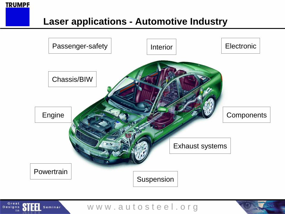
Exhaust systems
Chassis/BIW
Suspension
Electronic Interior Passenger-safety
Engine
Powertrain
Components
Laser applications - Automotive Industry
w w w . a u t o s t e e l . o r g
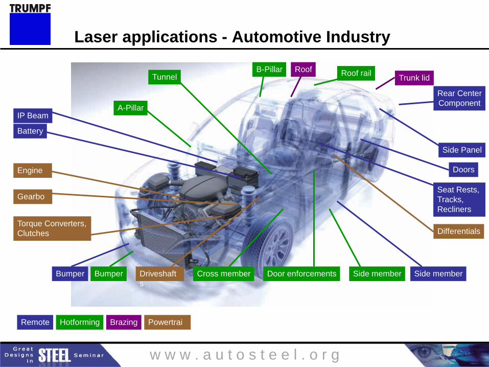
Powertrai
n
Engine
Torque Converters,
Clutches
Gearbo
x
Driveshaft
s
Differentials
Roof
Brazing
Trunk lid B-Pillar
Tunnel
Hotforming
A-Pillar
Side member Door enforcements Bumper
Roof rail
Cross member
Side Panel
Doors
Rear Center
Component
Seat Rests,
Tracks,
Recliners
Remote
Side member
IP Beam
Bumper
Battery
Laser applications - Automotive Industry
w w w . a u t o s t e e l . o r g
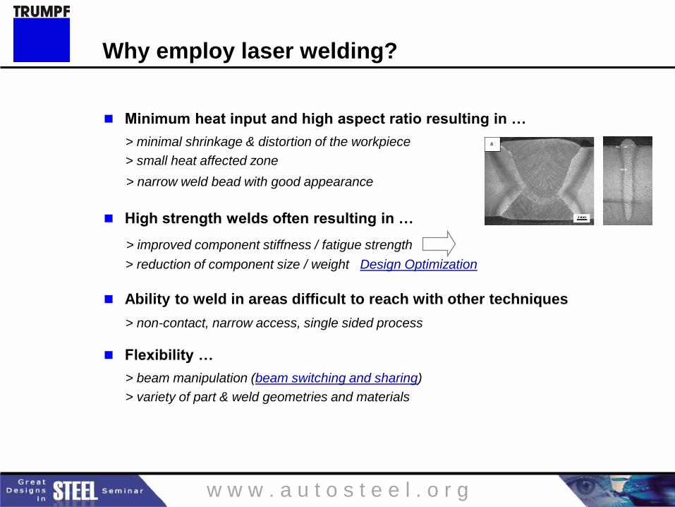
Minimum heat input and high aspect ratio resulting in …
> minimal shrinkage & distortion of the workpiece
> small heat affected zone
> narrow weld bead with good appearance
High strength welds often resulting in …
> improved component stiffness / fatigue strength
> reduction of component size / weight Design Optimization
Ability to weld in areas difficult to reach with other techniques
> non-contact, narrow access, single sided process
Flexibility …
> beam manipulation (beam switching and sharing)
> variety of part & weld geometries and materials
Why employ laser welding?
w w w . a u t o s t e e l . o r g
Cost savings ...
> high productivity >> faster cycle time = less stations & less floor space
> reduction of manual labor, scrap & re-work
> reduction of component material and weight
> can eliminate secondary processes
Laser Welding vs. Resistance Spot Welding
Reduction or elimination of flanges
> reduction of component size / weight
> reduced cost
> greater visibility / accessibility
Increased strength / stiffness
> localized increase of component strength / stiffness / fatigue strength
> weld shape optimization for component loading / stresses
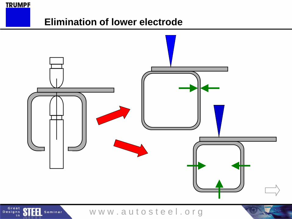
> elimination of lower electrode access holes
Why employ laser welding?
w w w . a u t o s t e e l . o r g
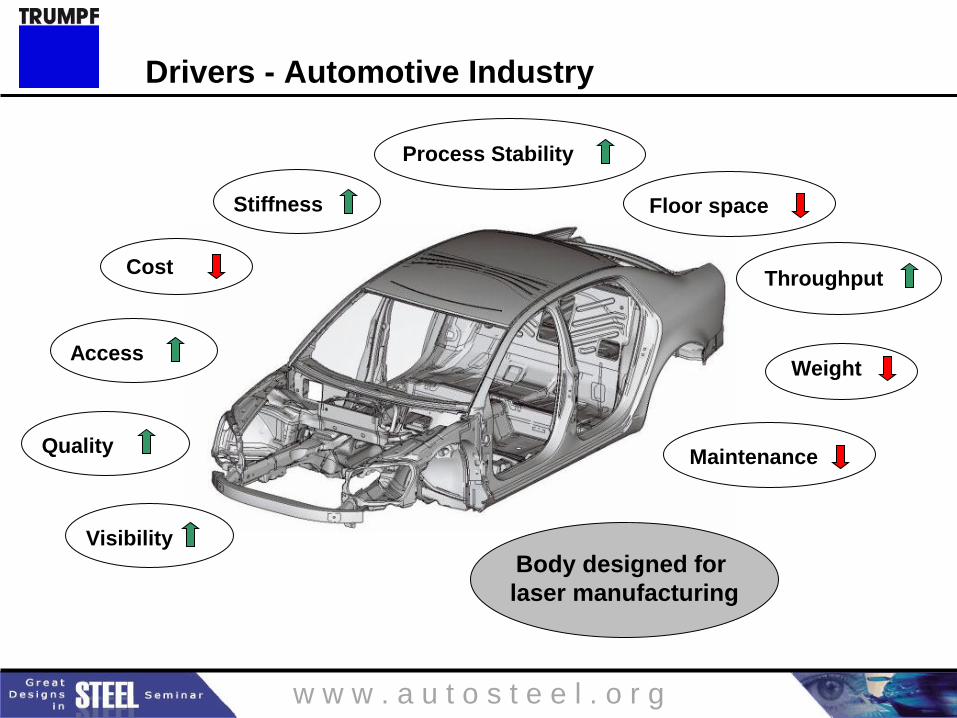
Weight
Stiffness
Cost
Process Stability
Quality
Body designed for
laser manufacturing
Visibility
Access
Throughput
Maintenance
Floor space
Drivers - Automotive Industry
w w w . a u t o s t e e l . o r g
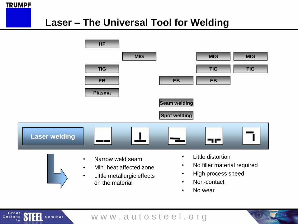
EB
Spot welding
TIG TIG
Plasma
TIG
HF
MIG
Seam welding
MIG
EB EB
MIG
Laser welding
• Narrow weld seam
• Min. heat affected zone
• Little metallurgic effects
on the material
• Little distortion
• No filler material required
• High process speed
• Non-contact
• No wear
Laser – The Universal Tool for Welding
w w w . a u t o s t e e l . o r g
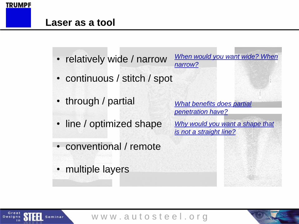
• relatively wide / narrow
• continuous / stitch / spot
• through / partial
• line / optimized shape
• conventional / remote
• multiple layers
When would you want wide? When
narrow?
Why would you want a shape that
is not a straight line?
What benefits does partial
penetration have?
Laser as a tool
w w w . a u t o s t e e l . o r g
1. Causes of porosity, underfill, undercut:
Volatile constituents (e.g. S, P)
Volatile coatings/surface contaminants (e.g. Zn, oil based lubricants)
Notes for welding of Zn coated steels in overlap configuration
a. Increased weld length may compensate for porosity in non-critical components
b. Electro-galvanized & electro-galvaneal are better than hot dipped galvanized
c. Bare to Zn is often okay (especially electro plated)
d. Zn to Zn configurations usually require a gap and/or Zn exhaust path for
reasonable results (e.g. dimples, shims, knurling, fixture/tooling, leading
pressure finger, part design, joint design)
e. Watch out for patent infringements!
Material selection
w w w . a u t o s t e e l . o r g
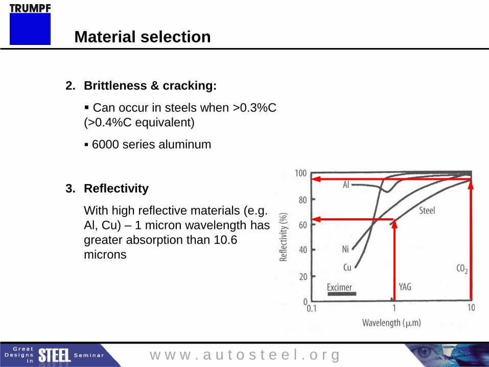
2. Brittleness & cracking:
Can occur in steels when >0.3%C
(>0.4%C equivalent)
6000 series aluminum
3. Reflectivity
With high reflective materials (e.g.
Al, Cu) – 1 micron wavelength has
greater absorption than 10.6
microns
Material selection
w w w . a u t o s t e e l . o r g
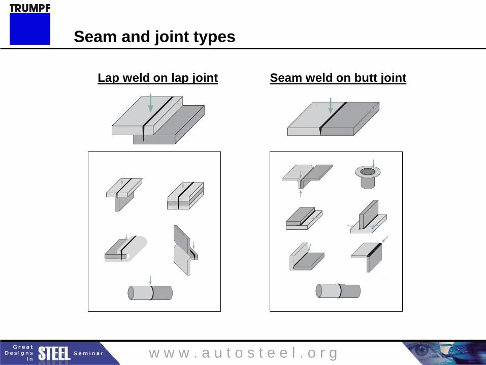
Lap weld on lap joint Seam weld on butt joint
Seam and joint types
w w w . a u t o s t e e l . o r g
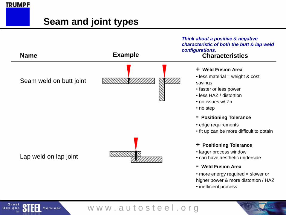
Name
Seam weld on butt joint
Lap weld on lap joint
Example Characteristics
+ Weld Fusion Area
• less material = weight & cost
savings
• faster or less power
• less HAZ / distortion
• no issues w/ Zn
• no step
- Positioning Tolerance
• edge requirements
• fit up can be more difficult to obtain
+ Positioning Tolerance
• larger process window
• can have aesthetic underside
- Weld Fusion Area
• more energy required = slower or
higher power & more distortion / HAZ
• inefficient process
Think about a positive & negative
characteristic of both the butt & lap weld
configurations.
Seam and joint types
w w w . a u t o s t e e l . o r g
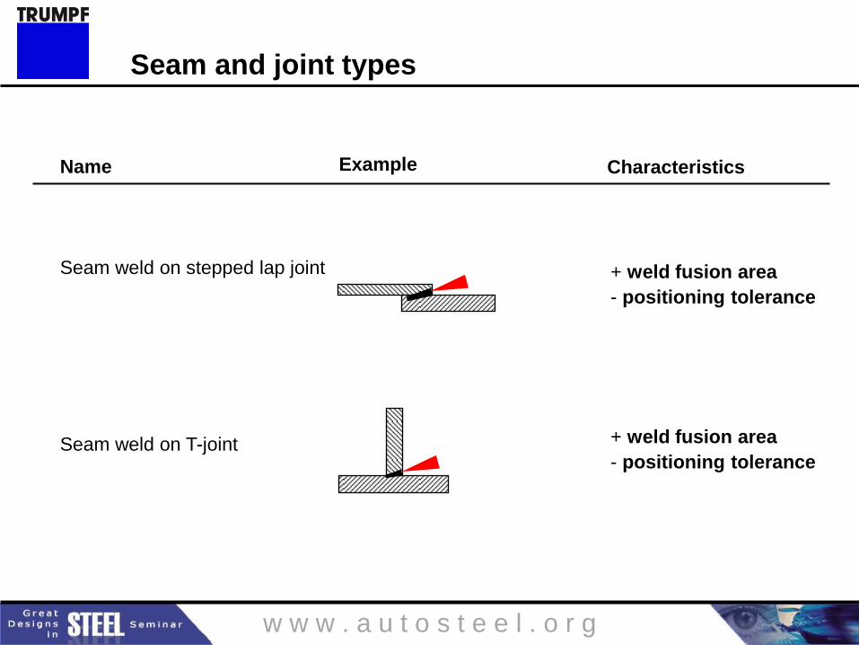
Name
Seam weld on stepped lap joint
Seam weld on T-joint
Example Characteristics
+ weld fusion area
- positioning tolerance
+ weld fusion area
- positioning tolerance
Seam and joint types
w w w . a u t o s t e e l . o r g
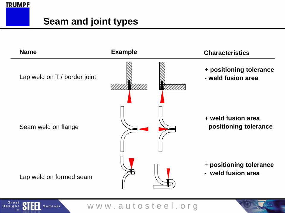
Name
Lap weld on T / border joint
Seam weld on flange
Lap weld on formed seam
Example Characteristics
+ positioning tolerance
- weld fusion area
+ weld fusion area
- positioning tolerance
+ positioning tolerance
- weld fusion area
Seam and joint types
w w w . a u t o s t e e l . o r g
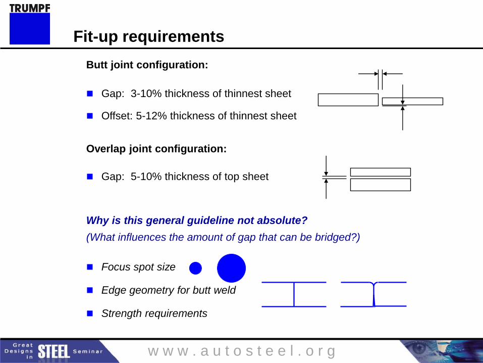
Butt joint configuration:
Gap: 3-10% thickness of thinnest sheet
Offset: 5-12% thickness of thinnest sheet
Overlap joint configuration:
Gap: 5-10% thickness of top sheet
Why is this general guideline not absolute?
(What influences the amount of gap that can be bridged?)
Focus spot size
Edge geometry for butt weld
Strength requirements
Fit-up requirements
w w w . a u t o s t e e l . o r g
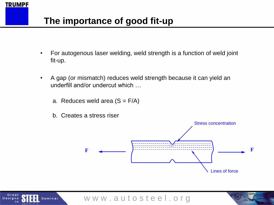
The importance of good fit-up
• For autogenous laser welding, weld strength is a function of weld joint
fit-up.
• A gap (or mismatch) reduces weld strength because it can yield an
underfill and/or undercut which …
a. Reduces weld area (S = F/A)
b. Creates a stress riser
F F
Stress concentration
Lines of force
w w w . a u t o s t e e l . o r g
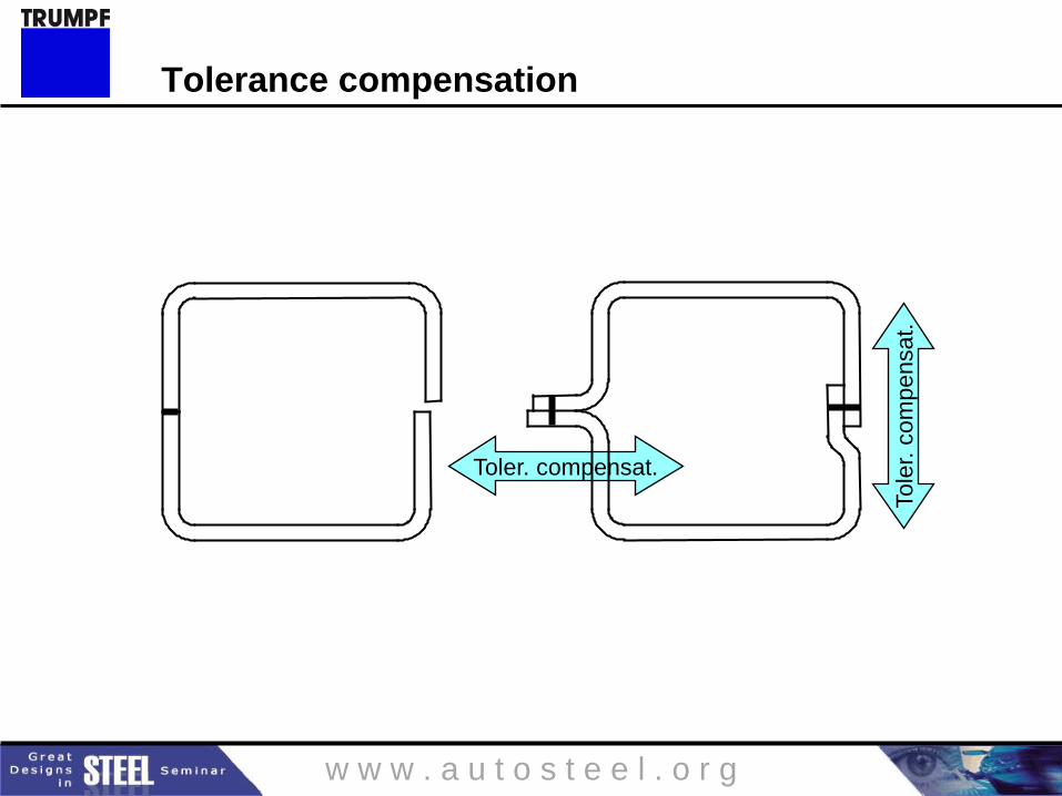
Toler. compensat.
Tole
r. c
om
pen
sat.
Tolerance compensation
w w w . a u t o s t e e l . o r g
Toler. compensat.
Tole
r. c
om
pen
sat.
Toler. compensat.
Tole
r. c
om
pen
sat.
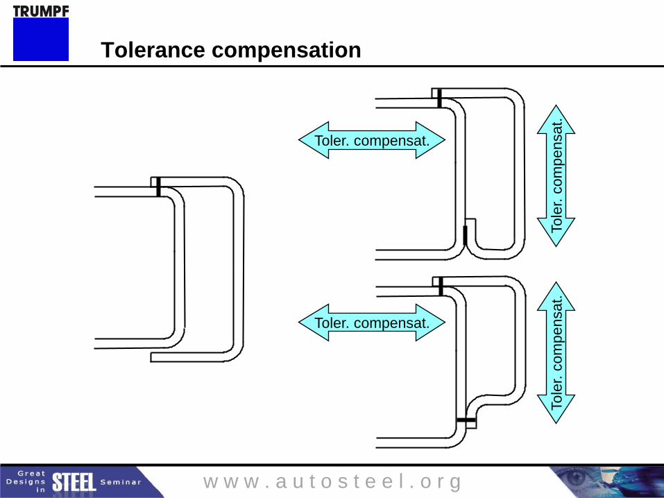
Tolerance compensation
w w w . a u t o s t e e l . o r g
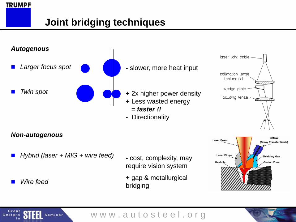
Autogenous
Larger focus spot
Twin spot
Non-autogenous
Hybrid (laser + MIG + wire feed)
Wire feed
+ 2x higher power density
+ Less wasted energy
= faster !!
- Directionality
- slower, more heat input
- cost, complexity, may
require vision system
+ gap & metallurgical
bridging
Joint bridging techniques
w w w . a u t o s t e e l . o r g
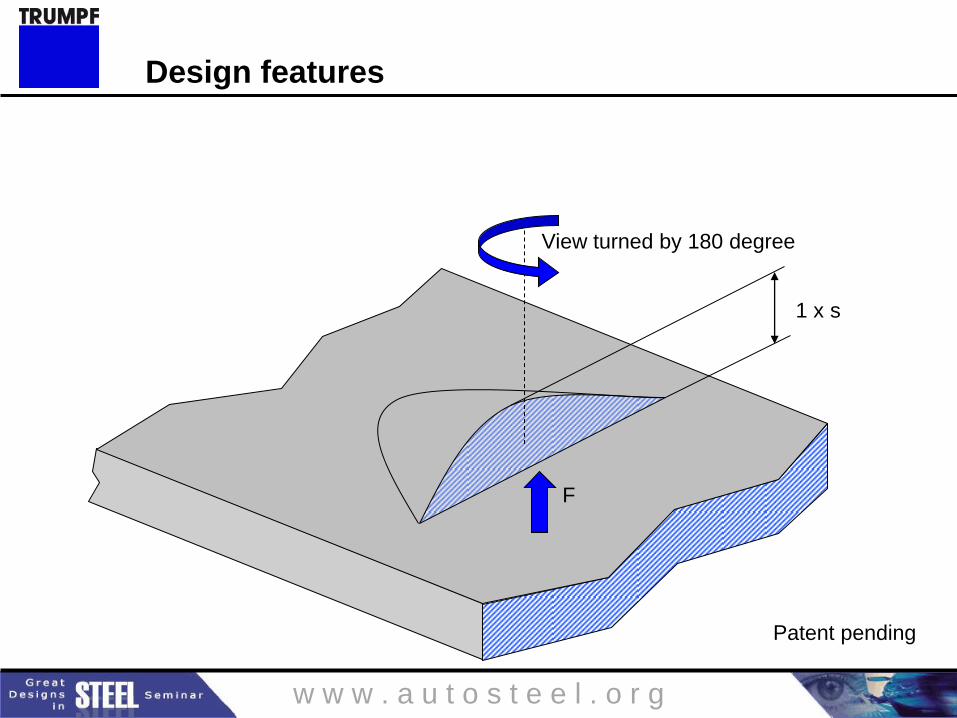
1 x s
F
View turned by 180 degree
Patent pending
Design features
w w w . a u t o s t e e l . o r g
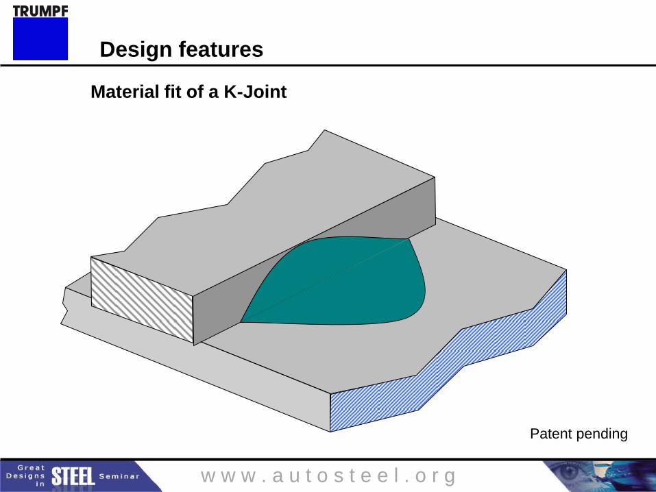
Patent pending
Design features
Material fit of a K-Joint
w w w . a u t o s t e e l . o r g
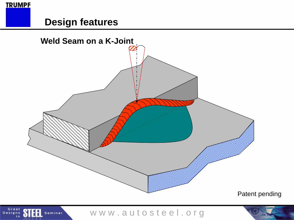
Patent pending
Design features
Weld Seam on a K-Joint
w w w . a u t o s t e e l . o r g
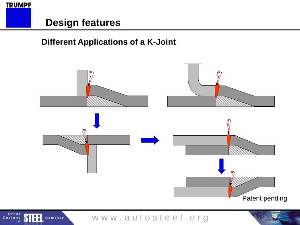
Patent pending
Design features
Different Applications of a K-Joint
w w w . a u t o s t e e l . o r g
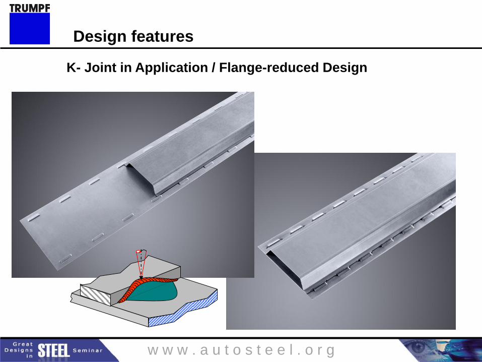
Design features
K- Joint in Application / Flange-reduced Design
w w w . a u t o s t e e l . o r g
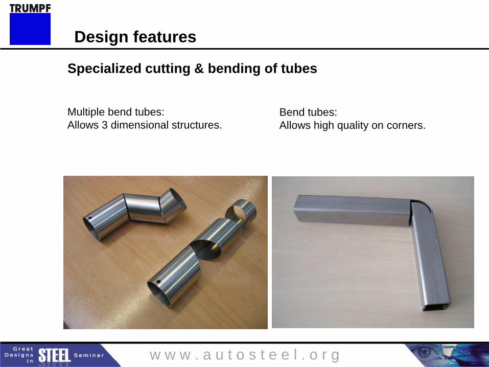
Multiple bend tubes:
Allows 3 dimensional structures.
Specialized cutting & bending of tubes
Bend tubes:
Allows high quality on corners.
Design features
w w w . a u t o s t e e l . o r g
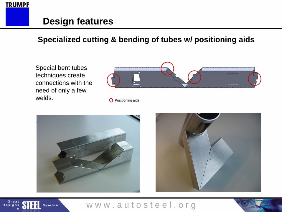
Positioning aids
Specialized cutting & bending of tubes w/ positioning aids
Special bent tubes
techniques create
connections with the
need of only a few
welds.
Design features
w w w . a u t o s t e e l . o r g
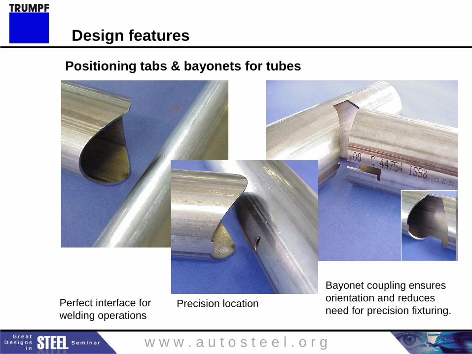
Perfect interface for
welding operations Precision location
Bayonet coupling ensures
orientation and reduces
need for precision fixturing.
Design features
Positioning tabs & bayonets for tubes

w w w . a u t o s t e e l . o r g
Design features
– Coding system
to avoid possible assembly
mistakes,
accurate position.
More Tube Interfaces
w w w . a u t o s t e e l . o r g
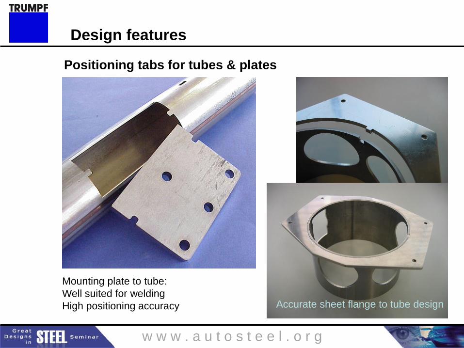
Accurate sheet flange to tube design
Mounting plate to tube:
Well suited for welding
High positioning accuracy
Design features
Positioning tabs for tubes & plates
w w w . a u t o s t e e l . o r g
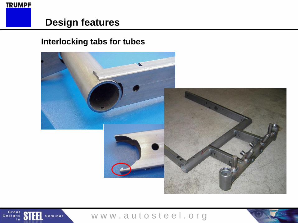
Interlocking tabs for tubes
Design features
w w w . a u t o s t e e l . o r g
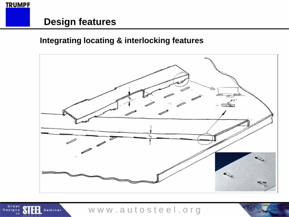
Integrating locating & interlocking features
Design features
w w w . a u t o s t e e l . o r g
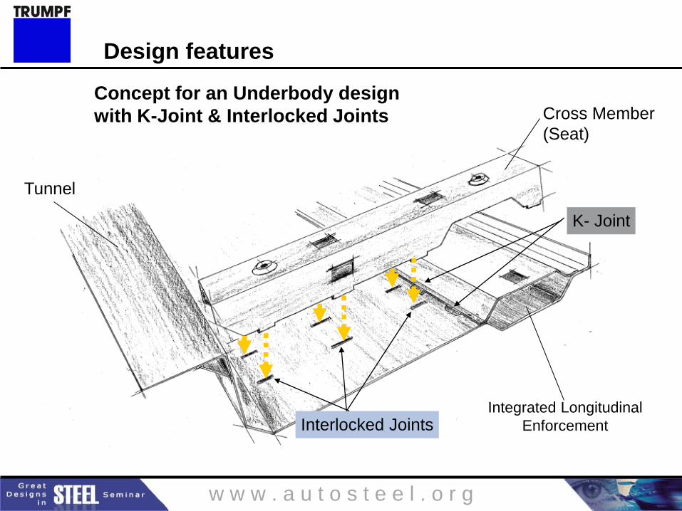
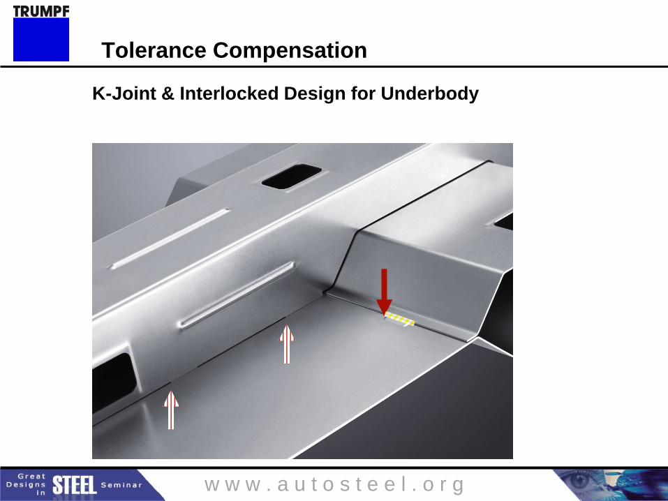
Tunnel
Cross Member
(Seat)
Integrated Longitudinal
Enforcement
K- Joint
Interlocked Joints
Design features
Concept for an Underbody design
with K-Joint & Interlocked Joints
w w w . a u t o s t e e l . o r g
K-Joint & Interlocked Design for Underbody
Tolerance Compensation
w w w . a u t o s t e e l . o r g
Design & re-design components for laser welding
Reduce component weight & cost by reducing or eliminating
flange widths (enabled by single sided, narrow beam access)
Increase vehicle accessibility & driver visibility by reducing or
eliminating flange widths (enabled by single sided, narrow beam
access)
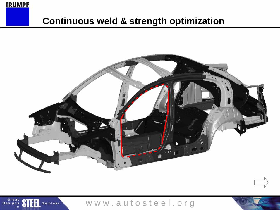
Reduce component weight and cost by reducing gage thickness
(enabled by increasing strength through optimized weld shapes
and/or continuous weld seams in high stress locations)
Reduce component weight and cost, and increase strength
(enabled by elimination of RSW lower electrode access holes in
structural reinforcements)
Design for laser welding summary (pt. 1)
w w w . a u t o s t e e l . o r g
Know & employ the strengths of the full variety of weld joint
styles
Realize there are several ways to bridge the gap, … but don’t
start there
Consider the variety of design features when designing for laser
welding (e.g. K-Joint, positioning aids, tabs, bayonets, interlocking joints,
tolerance compensation planes, etc.)
Design for laser welding summary (pt. 2)
w w w . a u t o s t e e l . o r g
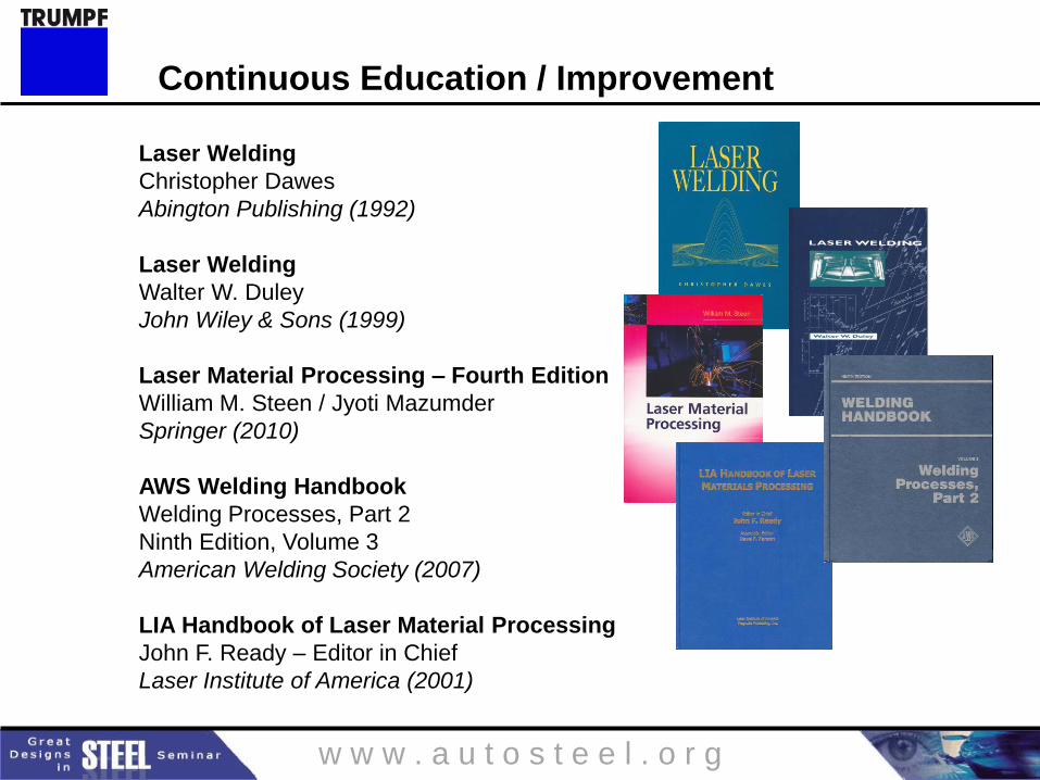
Laser Welding
Christopher Dawes
Abington Publishing (1992)
Laser Welding
Walter W. Duley
John Wiley & Sons (1999)
Laser Material Processing – Fourth Edition
William M. Steen / Jyoti Mazumder
Springer (2010)
AWS Welding Handbook
Welding Processes, Part 2
Ninth Edition, Volume 3
American Welding Society (2007)
LIA Handbook of Laser Material Processing
John F. Ready – Editor in Chief
Laser Institute of America (2001)
Continuous Education / Improvement
w w w . a u t o s t e e l . o r g
Please Join Us!
Thursday, May 17th
5:30 – 9:00 PM
5:30-6:00 Registration
6:00-6:20 Keynote address by Gary
Vasilash
6:30-9:00 Machine Demonstrations
TRUMPF Open House – Tomorrow Evening
w w w . a u t o s t e e l . o r g
Thank you
TRUMPF Laser Technology Center
Plymouth, MI
(734) 454-7200
w w w . a u t o s t e e l . o r g
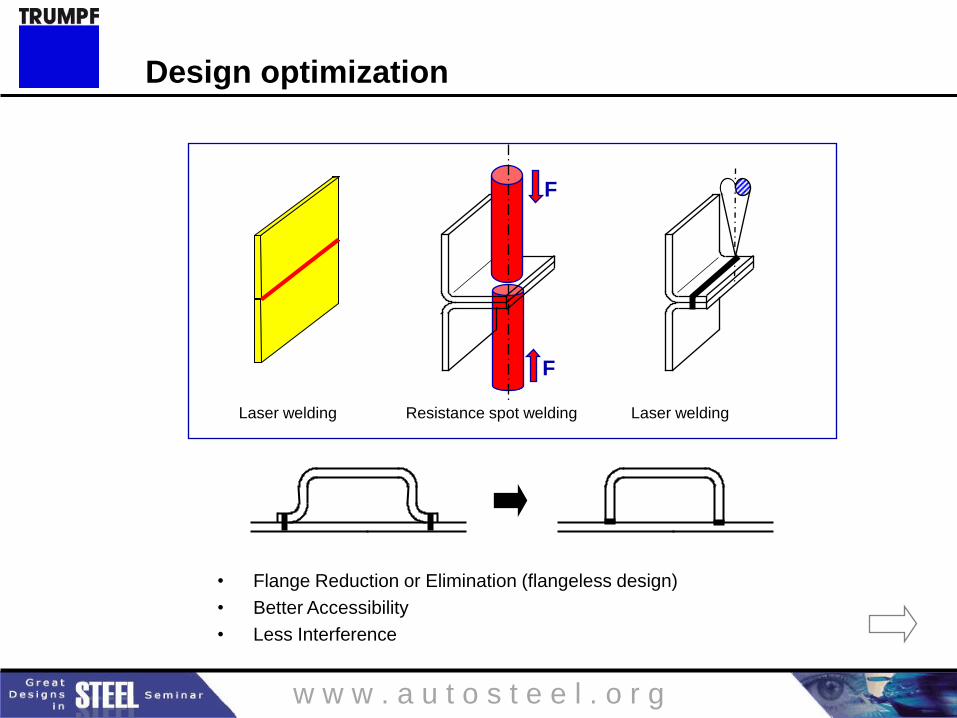
Design optimization
Resistance spot welding Laser welding
F
F
Laser welding
• Flange Reduction or Elimination (flangeless design)
• Better Accessibility
• Less Interference
w w w . a u t o s t e e l . o r g
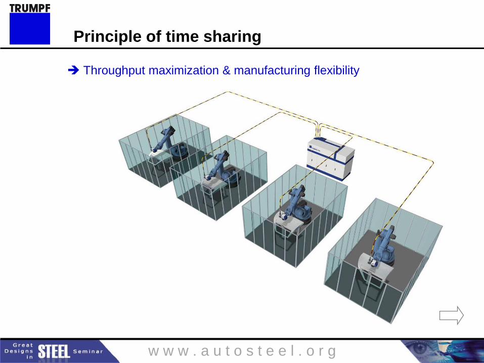
Principle of time sharing
Throughput maximization & manufacturing flexibility
w w w . a u t o s t e e l . o r g
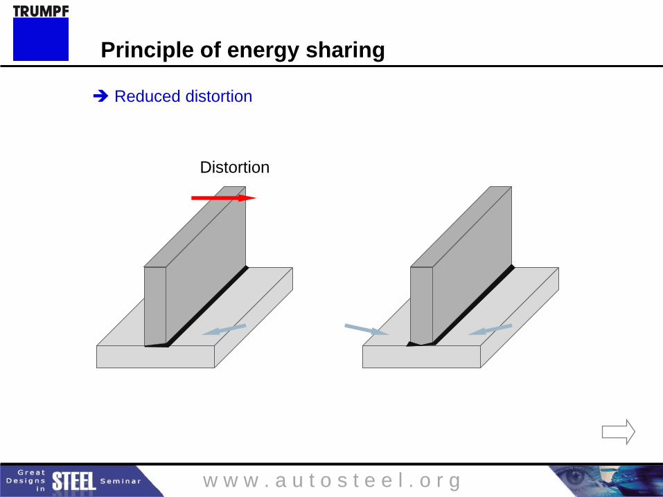
Distortion
Reduced distortion
Principle of energy sharing
w w w . a u t o s t e e l . o r g
Continuous weld & strength optimization
w w w . a u t o s t e e l . o r g
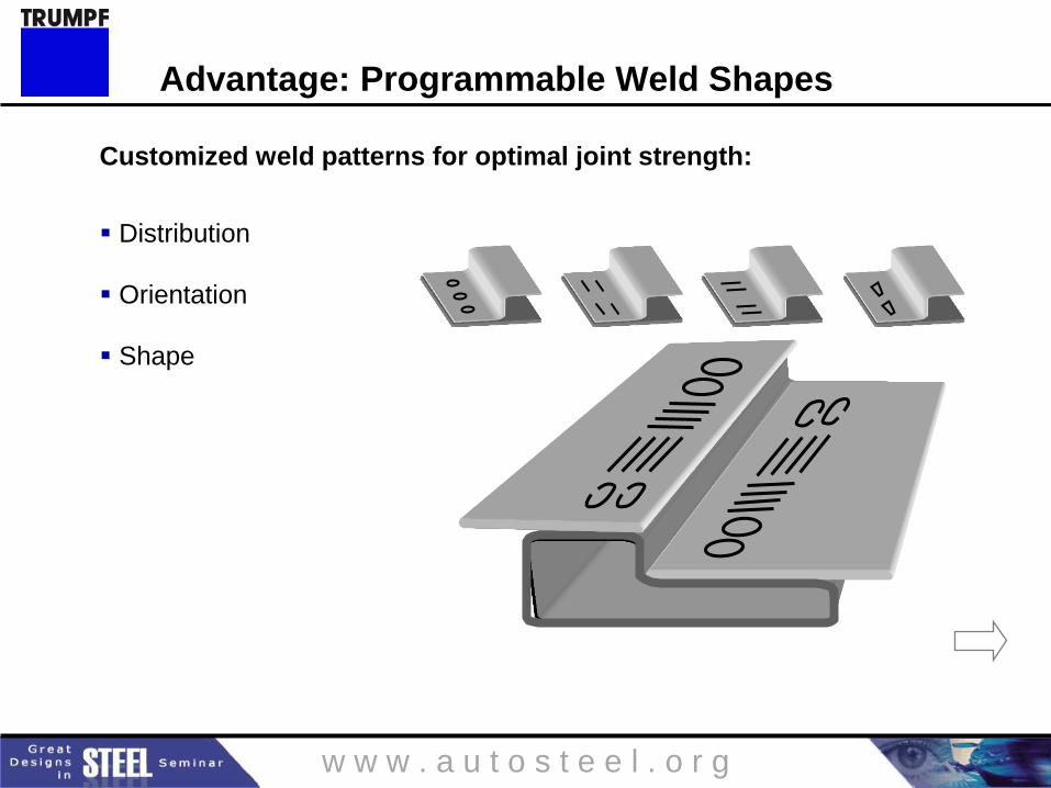
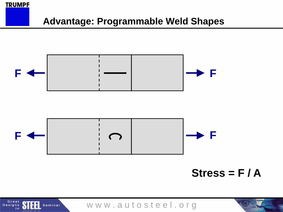
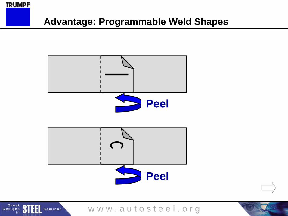
Advantage: Programmable Weld Shapes
Customized weld patterns for optimal joint strength:
Distribution Orientation Shape
w w w . a u t o s t e e l . o r g
Elimination of lower electrode
w w w . a u t o s t e e l . o r g
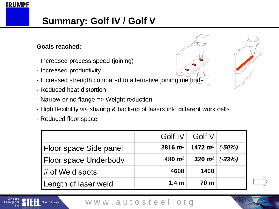
Golf IV Golf V
Floor space Side panel 2816 m2 1472 m2 (-50%)
Floor space Underbody 480 m2 320 m2 (-33%)
# of Weld spots 4608 1400
Length of laser weld 1.4 m 70 m
Goals reached:
- Increased process speed (joining)
- Increased productivity
- Increased strength compared to alternative joining methods
- Reduced heat distortion
- Narrow or no flange => Weight reduction
- High flexibility via sharing & back-up of lasers into different work cells
- Reduced floor space
Summary: Golf IV / Golf V
w w w . a u t o s t e e l . o r g
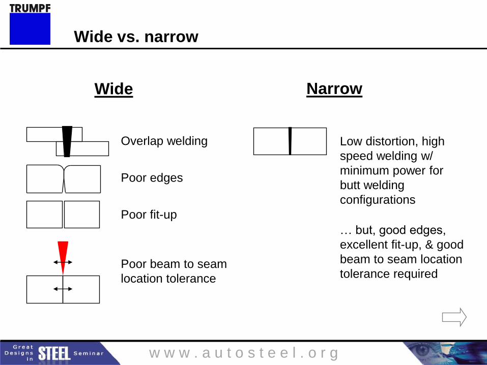
Narrow Wide
Overlap welding
Poor edges
Poor fit-up
Low distortion, high
speed welding w/
minimum power for
butt welding
configurations
… but, good edges,
excellent fit-up, & good
beam to seam location
tolerance required Poor beam to seam
location tolerance
Wide vs. narrow
w w w . a u t o s t e e l . o r g
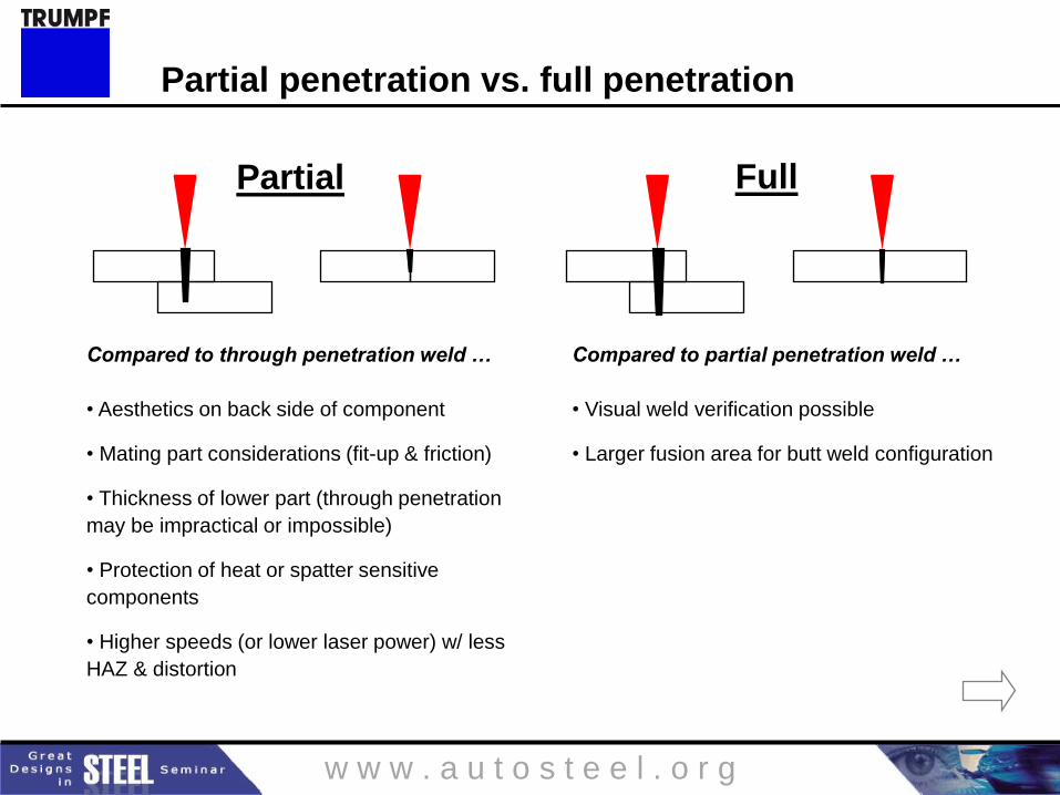
Compared to through penetration weld …
• Aesthetics on back side of component
• Mating part considerations (fit-up & friction)
• Thickness of lower part (through penetration
may be impractical or impossible)
• Protection of heat or spatter sensitive
components
• Higher speeds (or lower laser power) w/ less
HAZ & distortion
Compared to partial penetration weld …
• Visual weld verification possible
• Larger fusion area for butt weld configuration
Full Partial
Partial penetration vs. full penetration
w w w . a u t o s t e e l . o r g
F F
F F
Stress = F / A
Advantage: Programmable Weld Shapes
w w w . a u t o s t e e l . o r g
Peel
Peel
Advantage: Programmable Weld Shapes
w w w . a u t o s t e e l . o r g
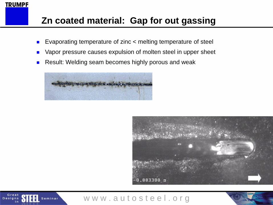
Evaporating temperature of zinc < melting temperature of steel
Vapor pressure causes expulsion of molten steel in upper sheet
Result: Welding seam becomes highly porous and weak
Zn coated material: Gap for out gassing
Zero Gap
w w w . a u t o s t e e l . o r g
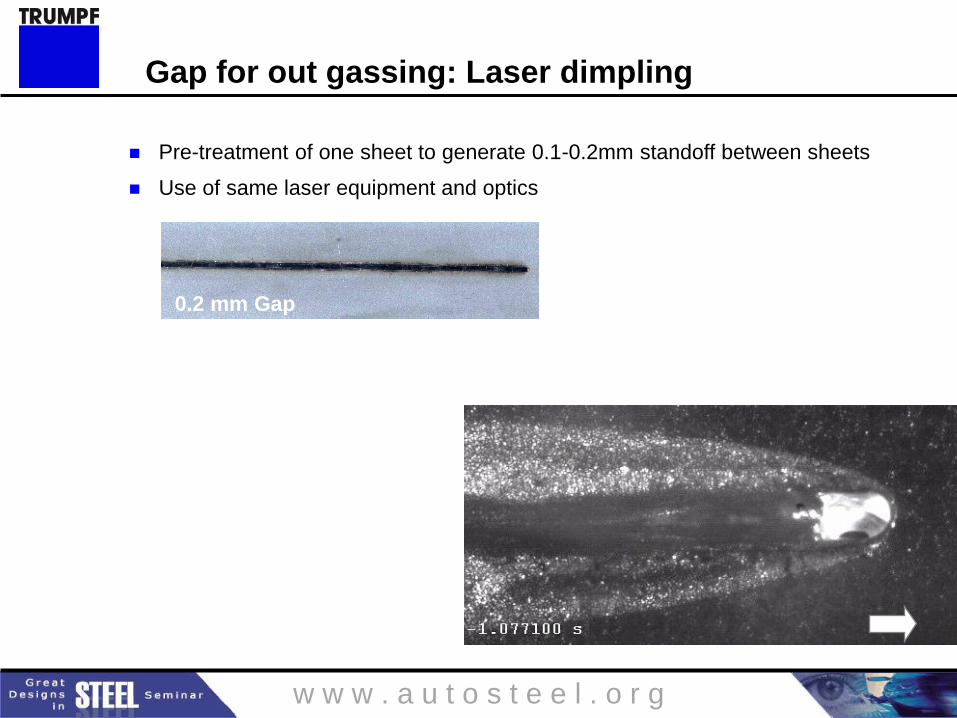
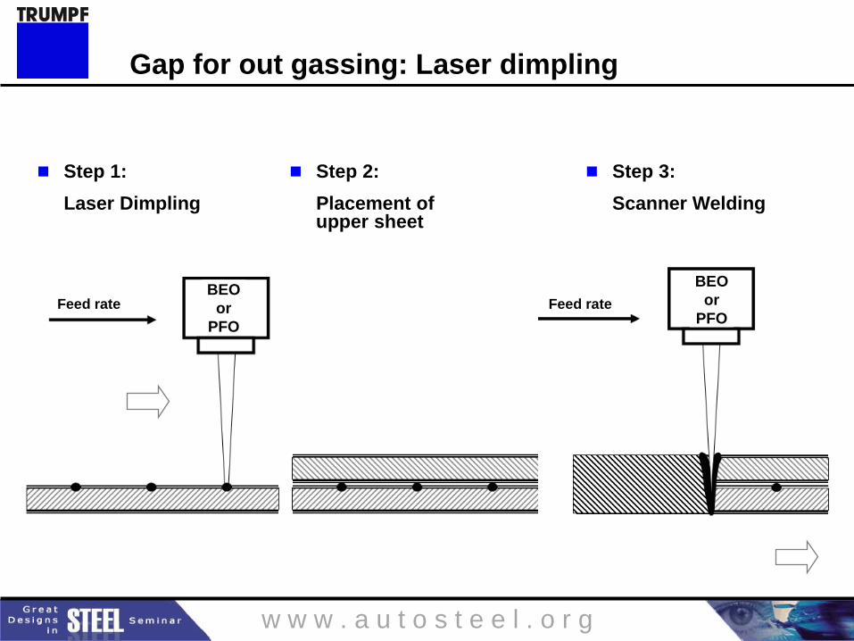
Pre-treatment of one sheet to generate 0.1-0.2mm standoff between sheets
Use of same laser equipment and optics
Gap for out gassing: Laser dimpling
0.2 mm Gap
w w w . a u t o s t e e l . o r g
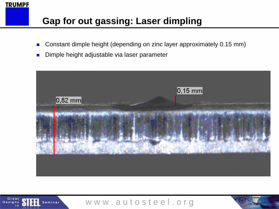
Constant dimple height (depending on zinc layer approximately 0.15 mm)
Dimple height adjustable via laser parameter
Gap for out gassing: Laser dimpling
w w w . a u t o s t e e l . o r g
Step 1:
Laser Dimpling
Step 2:
Placement of upper sheet
Step 3:
Scanner Welding
BEO
or
PFO
BEO
or
PFO Feed rate Feed rate
Gap for out gassing: Laser dimpling


