TECHNICAL UNIVERSITY of MALAYSIA, MELAKA Design for Robot Welding Rotation Jig with Workspace Thesis submitted in accordance with the requirement of the Technical University Malaysia, Melaka for the Degree of Bachelor of Engineering (Honours) Manufacturing (Robotic & Automation) By Muhammad Afiq Bin Zulkifli Faculty of Manufacturing Engineering April 2007
Transcript
TECHNICAL UNIVERSITY of MALAYSIA, MELAKA
Design for Robot Welding Rotation Jig with
Workspace
Thesis submitted in accordance with the requirement of the Technical University
Malaysia, Melaka for the Degree of Bachelor of Engineering (Honours)
Manufacturing (Robotic & Automation)
By
Muhammad Afiq Bin Zulkifli
Faculty of Manufacturing Engineering
April 2007
DECLARATION
I hereby, declare this thesis entitled “Design for Robot Welding Rotation Jig with
Workspace” is the result of my own research except as cited in the reference.
Signature : ……………………………
Author’s Name : Muhammad Afiq Bin Zulkifli
Date : 8 November 2006
APPROVAL
This thesis submitted to the senate of KUTKM and has been accepted as fulfillment of
the requirement for the degree of Bachelor of Manufacturing Engineering (Honours)
(Robotic and Automation). The members of the supervisory committee are as follows:
…………………………………………..
(MR SHARIMAN BIN ABDULLAH)
Main supervisor
Faculty of Manufacturing Engineering
iv
ABSTRACT
Jigs are work holders designed to hold, locate and support a work piece when robot
welding is weld the work piece. Jigs are widely used in manufacturing sector such as in
drilling machine and milling machine. In robot industry, jigs are commonly used for
robot welding. The purpose is to hold the work piece when the robot welds the work
piece because range of robot welding is limited. This project involves a design rotation
jig for robot welding and simulates the rotation jig and robot welding using the robot
simulation software called Workspace. Rotation jig is designed to improved the
versatility and extend the range of robotic arc welding system. Workspace is being used
to simulate the rotation jig and robot welding. This project is been started by study a
general consideration to design a jig and study about Workspace programming for
simulate the robot welding and rotation jig. Information from the study, rotation jig has
been designed. In the workspace programming, robot welding can be uploading from the
robot library and can be simulated with a rotation jig to. From the simulation, errors can
be tackled and this can help improve quality and productivity.
ii
ABSTRAK
Jig adalah sesuatu alat yang direka untuk memegang dan menyokong bahan kerja apabila
robot pengimpal mengimpal bahan kerja. Jig digunakan secara meluas di dalam sektor
pembuatan seperti contoh, jig digunakan pada mesin penggerudian dan mesin pengisaran.
Didalam industri robot, jig digunakan untuk robot pengimpal. Tujuan jig digunakan
didalam industri robot adalah untuk memgang dan menyokong bahan kerja semasa robot
pengimpal melakukan kerja. Ini adalah kerana robot pengimpal mempunyai darjah
kebebasan yang terhad. Kerja yang terlibat untuk menyiapkan projek ini adalah
merekabentuk jig yang boleh berputar untuk kegunaan robot pengimpal dan melakukan
simulasi terhadap robot pengimpal dan jig berputar dengan menggunakan perisian
simulasi iaitu ”Workspace 5”. Jig berputar direka untuk meningkatkan kualiti dan
membantu robot kimpalan mengimpal kimpalan yang tidak dapat dicapai oleh lengan
robot. Projek ini dimulakan dengan mempelajari dan menimbang syarat-syarat umum
untuk merekabentuk jig. Segala maklumat yang telah dikumpul akan digunakan untuk
merekabentuk jig. Robot tidak direka, tetapi diambil daripada perpustakaan perisian
simulasi iaitu ”Workspace 5”. Daripada aktiviti simulasi yang telah dilakukan, banyak
masalah yang timbul akan dapat diatasi.
iii
ACKNOWLEDGEMENT
Appreciations are expressed to those who have given generous contribution within the
period of this thesis development to fulfill the requirement of the Degree of Bachelor of
Engineering (Honors) Manufacturing (Robotic and Automation) program.
All praise for ALLAH, the mighty god for entire universe. With bless from
ALLAH, finally I manage to finish this project perfectly and successfully.
I would like to express my appreciation to Mr. Shariman Abdullah, my
supervisor. His support and encouragement was vital to the completion of this project.
Without his constant guide and teaching, is hard for me to completion this project.
I would like to thanks to Mr. Nizamul, lab technician for his support, helps and teaching
to completion this project. Furthermore, I also, would like to thanks all lecturers in
Manufacturing Engineering Faculty, for their teaching, guiding and support when I
studied in Technical University of Malaysia, Melaka.
I lot of thanks I would like to express to my beloved family, for their morale
support and helped when I was studying. Not to be forgotten, Umi Kalsom and all my
friends that involves directly or not, for helping me to completion this project.
Thank You
Muhammad Afiq Bin Zulkifli
April 2007
iv
TABLE OF CONTENT
Abstract i
Acknowledgement iii
Table of Content iv
List of Table viii
List of Figure ix
Sign and Symbol xi
1 INTRODUCTION 1
1.1 Background of Project 1
1.2 Gantt Chart 2
1.3 Objective of the Project 4
1.4 Scopes of the Project 4
1.5 Aims of the Project 4
2 LITERATURES REVIEW 5
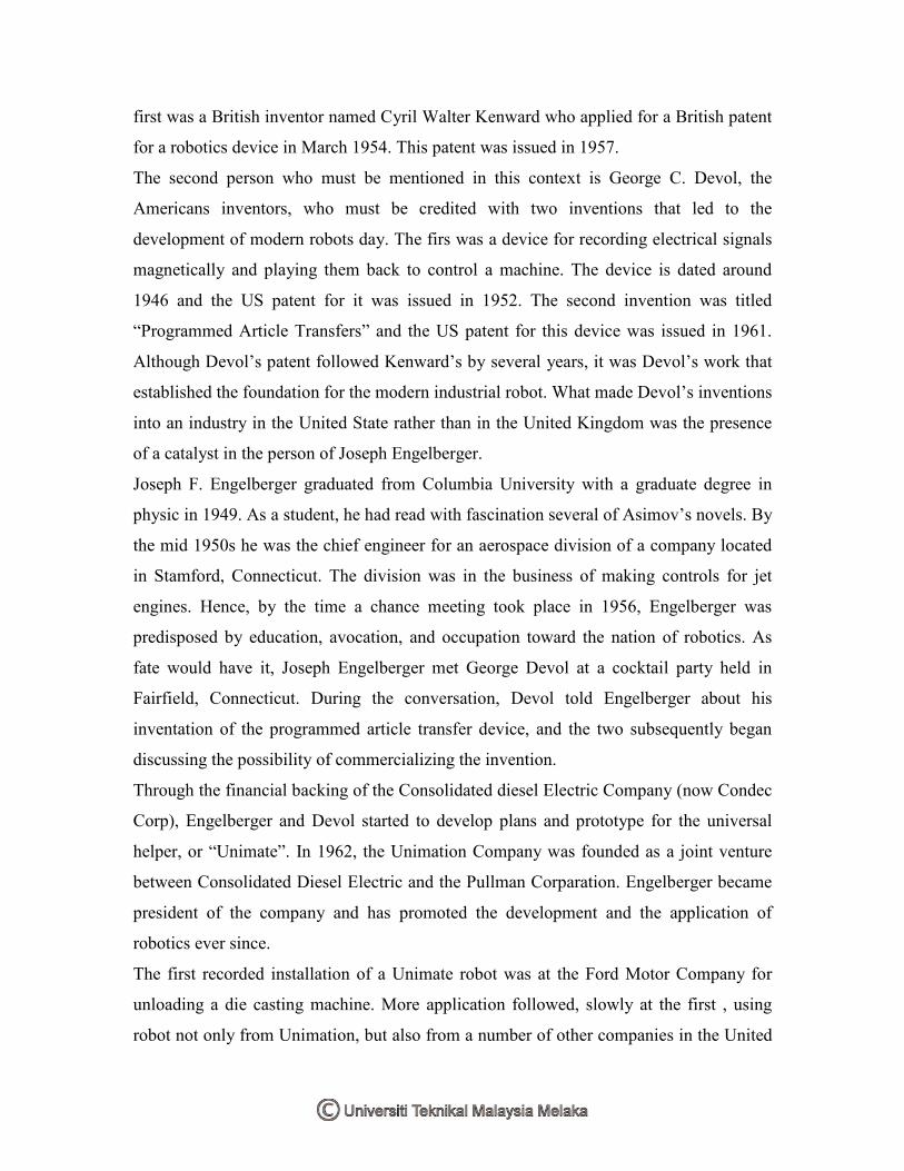
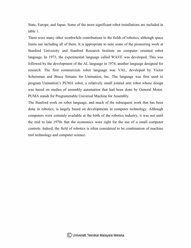
2.1 History of Robots 5-11
2.2 What is A Robot 12
2.3 Definition of Robots 12-13
2.4 What is Robotics 14
2.5 Robot Classification 15
2.5.1 The Superintelligence Robot 15
2.5.2 The Intelligence Robot 15
2.5.3 The Nonintelligence Robot 16
2.5.3.1 The Universal Robot 16
2.5.3.2 The Simple Robot 16
2.5.3.3 The Miniature Robot 16
2.6 Robot Welding 17
2.7 Robot for Arc Welding Application 18
2.8 Features of the Robot Arc Welding 19-20
v
2.9 Programming the Robot Arc Welding 21
2.10 The Arc Welding Robot Station 22
2.11 Tool 23
2.12 Tolerance 24
2.13 Joint Location and Joint Tracking 24
2.13.1 Joint Location 25
2.13.2 Joint Tracking 25
2.14 Sensor in Robot Arc Welding 27
2.14.1 Contact Arc Welding Sensors 27
2.14.2 Non Contact Arc Welding Sensors 28-29
2.15 Advantages and Benefit of Robot Arc Welding 31-32
2.16 Robot Simulation Software 33
2.16.1 Benefit of Robot Simulation Software 34
2.16.2 Why Need Robot Simulation Software 34-37
2.16.3 Type of Robot Simulation Software 38
2.17 Jigs 39
2.17.1 General Consideration to Design a Jigs 39
2.17.2 Machine Consideration 40
2.17.3 Rotation Jig 40-41
3 METHODOLOGY 42
3.1 Flowchart 43
3.2 Jig Design 44
3.2.1 First Designed 44-47
3.2.1.1 Jig Specification 45
3.2.1.2 Bill of Material 46
3.2.1.3 Support Ring, Discs and Flexi Strips 47
3.2.2 Second Design 48-50
3.2.2.1 Jigs Specification 49
3.2.2.2 Bill of Material 50
3.2.3 Jig Comparison 51
vi
3.3 Robot Selection 52
3.3.1 Basic Description 52
3.3.2 Selection Criteria 52
3.3.1 Drawing Details 53
3.4 Workspace Simulation 54
3.4.1 Loading A Robot To the Workspace 54-56
3.4.2 Importing another Model into Workspace 57-58
3.4.3 Load and Attach Tool 59-61
4 RESULT 62
4.1 Rotation Jig Improvement Design 62
4.1.1 Rotation Jig First Design 62-64
4.1.1.1 Jig Specification 64
4.1.1.2 Bill of Material 64
4.1.2 Rotation Jig Second Design 65-67
4.1.2.1 Jig Specification 66
4.1.2.2 Bill of Material 67
4.1.3 Jig Comparison 68
4.2 Simulating the Robot and Rotation Jig Using Workspace 69
4.3 Simulating Robot and Rotation Jig Using the Pendant 71
4.3.1 Adding Auxiliary Axis to the Rotation Jig 73
4.3.2 Creating the Joint and Defining the Auxiliary Axis 74-76
4.3.3 How to Move the Robot and Rotation Jig 77-82
4.4 Simulate the Robot and Rotation Jig Using Create Geometry Point
(GP) on an Edge
83
4.4.1 Creating a GP on Edge of Rotation Jig 83-86
4.5 Adding GP Tool Action 87
5 DISCUSSION 89
6 CONCLUSION and RECOMMENDATION 91
6.1 Conclusion 91-92
6.2 Recommendation 92
vii
REFERENCE 93
APPENDICE 96
viii
LIST OF TABLES
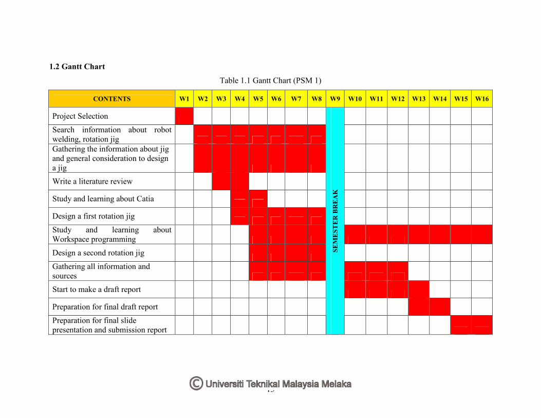
1.1 Gantt Chart (PSM 1) 2
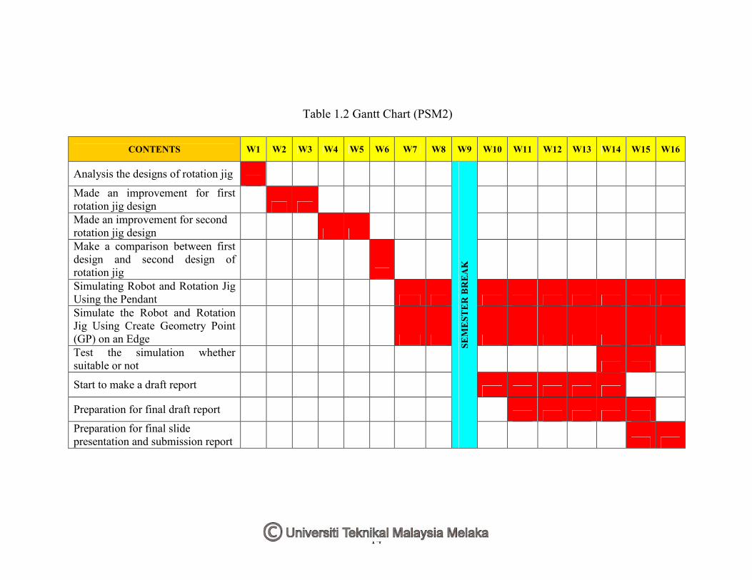
1.2 Gantt Chart (PSM 2) 3
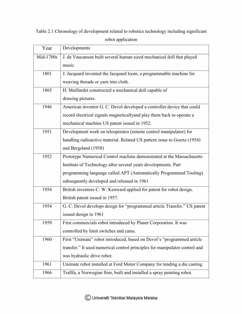
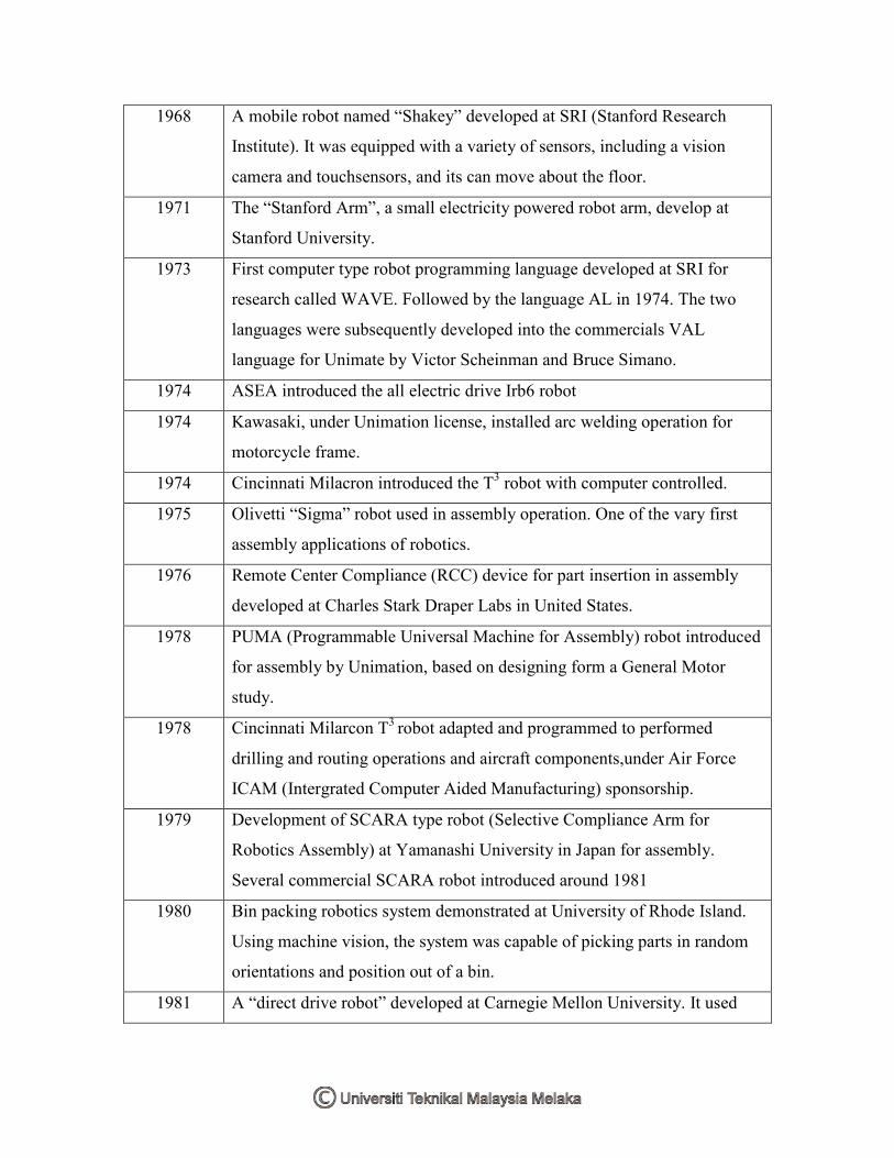
2.1 Chronology of development related to robotics technology 9
3.1 First Jig Specification 45
3.2 Bill of material for first designed 46
3.3 Second jig specification 49
3.4 Bill of Material for second design 50
3.5 Comparison between jigs 51
4.1 First Jig Specification 64
4.2 First Jig Bill of Material 64
4.3 Second Jig Specification 66
4.4 Second Jig Bill of Material 67
4.5 Rotation Jig Comparison 68
4.6 Position of the Robot and Rotation Jig 69
4.7 Position of the Rotational Joint 75
4.8 GPs and Joint Value 78
4.9 Create GP on an Edge 84
ix
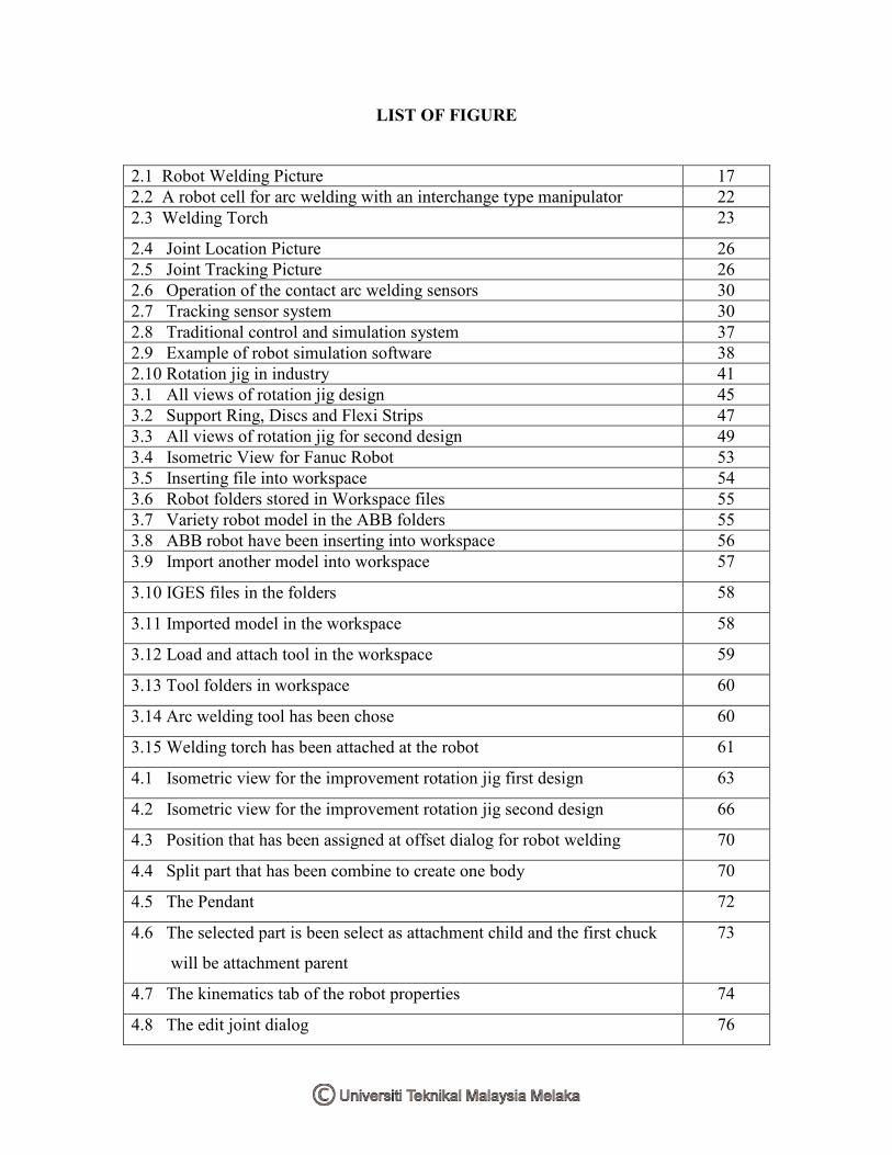
LIST OF FIGURE
2.1 Robot Welding Picture 17
2.2 A robot cell for arc welding with an interchange type manipulator 22
2.3 Welding Torch 23
2.4 Joint Location Picture 26
2.5 Joint Tracking Picture 26
2.6 Operation of the contact arc welding sensors 30
2.7 Tracking sensor system 30
2.8 Traditional control and simulation system 37
2.9 Example of robot simulation software 38
2.10 Rotation jig in industry 41
3.1 All views of rotation jig design 45
3.2 Support Ring, Discs and Flexi Strips 47
3.3 All views of rotation jig for second design 49
3.4 Isometric View for Fanuc Robot 53
3.5 Inserting file into workspace 54
3.6 Robot folders stored in Workspace files 55
3.7 Variety robot model in the ABB folders 55
3.8 ABB robot have been inserting into workspace 56
3.9 Import another model into workspace 57
3.10 IGES files in the folders 58
3.11 Imported model in the workspace 58
3.12 Load and attach tool in the workspace 59
3.13 Tool folders in workspace 60
3.14 Arc welding tool has been chose 60
3.15 Welding torch has been attached at the robot 61
4.1 Isometric view for the improvement rotation jig first design 63
4.2 Isometric view for the improvement rotation jig second design 66
4.3 Position that has been assigned at offset dialog for robot welding 70
4.4 Split part that has been combine to create one body 70
4.5 The Pendant 72
4.6 The selected part is been select as attachment child and the first chuck
will be attachment parent
73
4.7 The kinematics tab of the robot properties 74
4.8 The edit joint dialog 76
x
4.9 Position of rotational joint at spindle 76
4.10 Pendant dialog that has 7 axis 78
4.11 GPs that has been created at work piece 80
4.12 GPs that have been created is shown in the project view 81
4.13 GPs moves in the path shown in the project view 81
4.14 Simulation at robot name 82
4.15 Simulation activity 82
4.16 The create GPs on edge dialog 83
4.17 Create a GP on an edge 86
4.18 GPs that assigned at the edge 86
4.19 GP tool action dialog 87
4.20 GP properties action tab containing assigned tool action 87
4.21 Hammer icon 88
4.22 Tool action 88
11
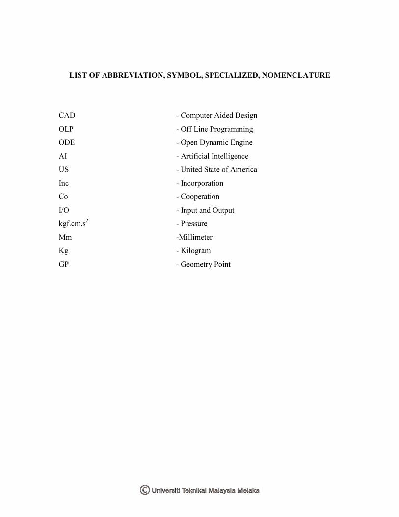
LIST OF ABBREVIATION, SYMBOL, SPECIALIZED, NOMENCLATURE
CAD - Computer Aided Design
OLP - Off Line Programming
ODE - Open Dynamic Engine
AI - Artificial Intelligence
US - United State of America
Inc - Incorporation
Co - Cooperation
I/O - Input and Output
kgf.cm.s2 - Pressure
Mm -Millimeter
Kg - Kilogram
GP - Geometry Point
12
CHAPTER 1
INTRODUCTION
1.1 Background of Project
Technology in this world is growing rapidly. All country in this world wants to be an
advanced in all of kind of things. Today, sophisticated machine and robots are being
developed to replace human in the work field. Machine such as robots are capable to do a
critical and dangerous jobs. Robots is not like a human that have a limitation when do a
job, robots can do anything without having any difficulties or tired like human when do a
job. Robots also can improved productivity, reduce a failure, and also improved a quality.
This project is specified to design a rotation jig for a robot welding. Rotation jig are
designed to holding are workpice or product that wants to be welding. Rotation jig are
also designed for automatic welding of parts and specified for high accuracy separate
setting, high overall performance, improved a quality of welded seams and to simplify
the welding work that need to be weld in the difficult or critical angle.
This project also is been done to looks an advantages a simulation for a robot welding
before some application is been done. With a simulation software, errors can be reduced,
increased a flexibility, decreased risks of disinvestments are achieved through superior
planning and quicker adaptation rates in the production.