The observations presented in this paper arebased on the authors’ experience—mostlynegative and difficult—of sampling mineralprocessing plants at several hundred sites overa few decades and across a number ofcontinents.
A modern mineral processing plantrepresents a substantial investment. Duringthe design process, there is often a periodwhen costs (or overruns) must becompensated for by cuts in capital expenditure.In many cases, sampling and measurementequipment provides a soft target for such‘savings’.
If we do make these ‘savings’, how can weaccurately measure the plant performance foroptimization?
This paper considers why making this‘saving’ is a very poor strategy and outlinessome ideas that are simple to include at designbut difficult and expensive to retrofit.
More accurate measurement simplifies andenables sensible and correct decision making.
For example:Consider a 1000 t/h processing plant which
achieves a 0.5% improvement in throughput atgrind at target size. This is an additional 5 t/hfor 360*24*0.9 or 38 880 t over a year at 90%combined availability and utilization.
A plant which nets less than USD10-20 perton processed (after mining costs) will not be agood long-term prospect. Hence, each 0.5%improvement which can be measured andverified is worth 0.4–0.8 million US dollars onthe bottom line.
As there are potentially many more 0.5%improvements than 1% improvements, letalone 5% improvements, the perception thatsampling is an ‘optional extra’, which may beomitted to ‘save money’, has a very poorbusiness case indeed. Omitting sampling andmeasurement will ‘save’ profit as well asencouraging poor asset management andsacrificing future benefits.
Sampling objectives
The objectives of sampling can be broadlycategorized as: measurement of production,metallurgical accounting/corporategovernance, trouble-shooting, andoptimization surveys. These are expandedupon in Table I.
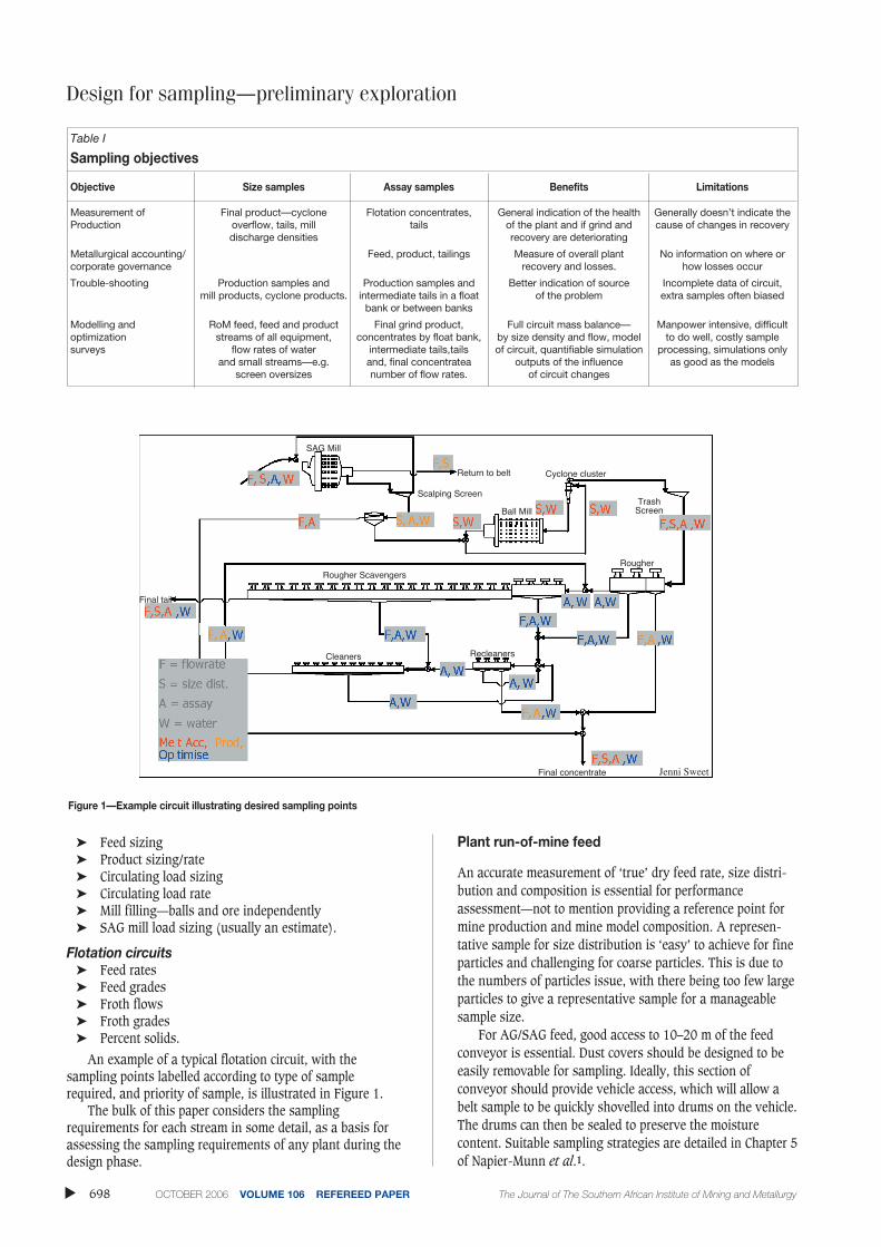
Generalized objectives for each part of acircuit for a full survey are given in Table I.The listed data apply to each piece ofequipment around the circuit. Additionally,equipment dimensions, power, pressure, etcare required.
Comminution circuits
➤ Feed rate➤ Feed moisture
Design for sampling—preliminaryexplorationby R. Morrison* and M. Powell†
Synopsis
A modern mineral processing plant represents a substantialinvestment. During the design process, there is often a period whencosts (or overruns) must be compensated for by cuts in capitalexpenditure. In many cases, sampling and measurement equipmentprovides a soft target for such ‘savings’.
This process is almost analogous to reducing the capitalinvestment in a corner store by not including a cash register. Theconsequences will be quite similar—a serious lack of soundperformance data and plenty of opportunities for theft— deliberateor inadvertent.
This paper makes the case that investment in sampling andmeasurement equipment is more cost-effective during the designphase. Further, a strong measurement culture will have manybenefits including the ability to take advantage of small gains. Inalmost any business, there are many more opportunities to makesmall gains than to make large, step changes.
In short, if a project cannot justify the cost of accurate andreliable measurement of its performance, it probably should not be aproject at all.
* JKMRC, The University of Queensland, Brisbane,Australia.
† MPRU, University of Cape Town, Rondebosch, SouthAfrica.
An example of a typical flotation circuit, with thesampling points labelled according to type of samplerequired, and priority of sample, is illustrated in Figure 1.
The bulk of this paper considers the samplingrequirements for each stream in some detail, as a basis forassessing the sampling requirements of any plant during thedesign phase.
Plant run-of-mine feed
An accurate measurement of ‘true’ dry feed rate, size distri-bution and composition is essential for performanceassessment—not to mention providing a reference point formine production and mine model composition. A represen-tative sample for size distribution is ‘easy’ to achieve for fineparticles and challenging for coarse particles. This is due tothe numbers of particles issue, with there being too few largeparticles to give a representative sample for a manageablesample size.
For AG/SAG feed, good access to 10–20 m of the feedconveyor is essential. Dust covers should be designed to beeasily removable for sampling. Ideally, this section ofconveyor should provide vehicle access, which will allow abelt sample to be quickly shovelled into drums on the vehicle.The drums can then be sealed to preserve the moisturecontent. Suitable sampling strategies are detailed in Chapter 5of Napier-Munn et al.1.
▲
698 OCTOBER 2006 VOLUME 106 REFEREED PAPER The Journal of The Southern African Institute of Mining and Metallurgy
Measurement of Final product—cyclone Flotation concentrates, General indication of the health Generally doesn’t indicate theProduction overflow, tails, mill tails of the plant and if grind and cause of changes in recovery
discharge densities recovery are deteriorating
Metallurgical accounting/ Feed, product, tailings Measure of overall plant No information on where or corporate governance recovery and losses. how losses occur
Trouble-shooting Production samples and Production samples and Better indication of source Incomplete data of circuit, mill products, cyclone products. intermediate tails in a float of the problem extra samples often biased
bank or between banks
Modelling and RoM feed, feed and product Final grind product, Full circuit mass balance— Manpower intensive, difficultoptimization streams of all equipment, concentrates by float bank, by size density and flow, model to do well, costly sample surveys flow rates of water intermediate tails,tails of circuit, quantifiable simulation processing, simulations only
and small streams—e.g. and, final concentratea outputs of the influence as good as the modelsscreen oversizes number of flow rates. of circuit changes
At least a 5 m section should be well lit to allow digitalphotos to be taken to monitor feed size variation duringtesting. For new plant design it is strongly recommended thata camera imaging system is installed to give an onlinesample of feed size— especially for AG/SAG mills.
As both valuable minerals and moisture tend to beconcentrated into finer size fractions, it is useful to measureassays and moisture by size fraction to allow errors due tosize sampling to be estimated. This is sometimes impracticalfor moisture. However, in many cases, the coarser fractionsare ‘dry’ for all practical purposes and the percentage finerthan a few millimetres will be a more accurate estimator ofmoisture content than any direct measurement.
The wet feed rate to the mill usually does justify an‘accurate’ weightometer. A suitable unit should use fouridlers and be provided with a roller chain for quick andaccurate calibration and checking. Reliable performance alsorequires accurate alignment of conveyor belt and weighframe. An area that often receives insufficient attention isbelt speed measurement. This is of serious concern as anerror in this measurement is almost always a bias.
For toll treatment, the feed material should be truckedover a certified weigh bridge and the empty truck tared onthe way out.
Toll treatment is given special mention as it is becomingmore common to treat ores that come from many sourceswith different owners or business units. It therefore becomesimperative to measure mass and grade delivered from thesesources.
The mining division of an organization may not acceptin-circuit sampling—especially if there are concentrationdevices within the grinding circuit. Hence primary ore feedsampling will sometime be a necessity.
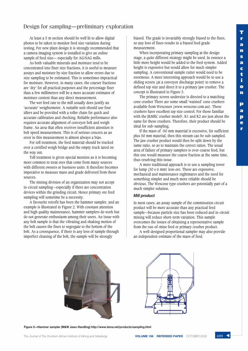
A favourite retrofit has been the hammer sampler, and anexample is illustrated in Figure 2. With constant attentionand high quality maintenance, hammer samplers do work butdo not generate enthusiasm among their users. An issue withany belt sample is that the vibrating and shaking motion ofthe belt causes the fines to segregate to the bottom of thebelt. As a consequence, if there is any loss of sample throughimperfect cleaning of the belt, the sample will be strongly
biased. The grade is invariably strongly biased to the fines,so any loss of fines results in a biased feed grademeasurement.
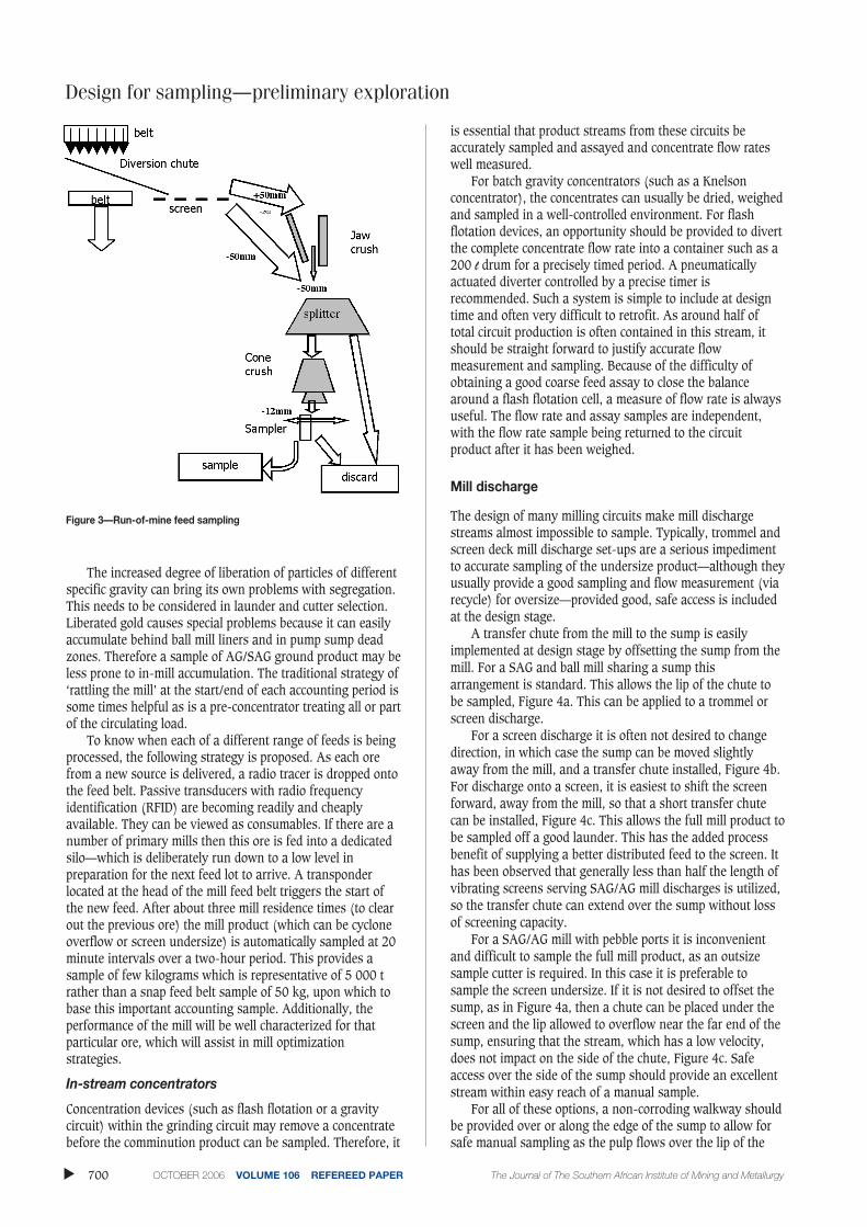
When incorporating primary sampling at the designstage, a quite different strategy might be used. In essence alittle more height would be added to the feed system. Addedheight is expensive but would allow for much simplersampling. A conventional sample cutter would need to beenormous. A more interesting approach would be to use asliding screen (at a conveyor discharge point) to remove adefined top size and direct it to a primary jaw crusher. Theconcept is illustrated in Figure 3.
The primary screen undersize is directed to a matchingcone crusher There are some small ‘waisted’ cone crushersavailable from Wescones (www.wescone.com.au). Thesecrushers have excellent top size control. For those familiarwith the JKMRC crusher model1, K1 and K2 are just about thesame for these crushers. Therefore, their product should beideal for sub-sampling.
If the mass of -50 mm material is excessive, for sufficientplus 50 mm material, then this stream can be sub-sampled.The jaw crusher product would then be split down by thesame ratio, so as to maintain the correct ratios. The usualarea of failure of primary samplers is over-coarse feed, butthis one would measure the coarse fraction at the same time,thus resolving this issue.
A more traditional approach is to use a sampling towerfor lump (30 x 6 mm) iron ore. These are expensive,mechanical and maintenance nightmares and the need forsomething simpler and much more reliable should beobvious. The Wescone type crushers are potentially part of amuch simpler solution.
Mill product
In most cases, an assay sample of the comminution circuitproduct will be more accurate than any practical feedsample—because particle size has been reduced and in-circuitmixing will reduce short-term variation. This sampleovercomes the issues of obtaining a representative samplefrom the run-of-mine feed or primary crusher product.
A well-designed proportional sampler may also providean independent estimate of the mass of feed.
Design for sampling—preliminary exploration
The Journal of The Southern African Institute of Mining and Metallurgy VOLUME 106 REFEREED PAPER OCTOBER 2006
The increased degree of liberation of particles of differentspecific gravity can bring its own problems with segregation.This needs to be considered in launder and cutter selection.Liberated gold causes special problems because it can easilyaccumulate behind ball mill liners and in pump sump deadzones. Therefore a sample of AG/SAG ground product may beless prone to in-mill accumulation. The traditional strategy of‘rattling the mill’ at the start/end of each accounting period issome times helpful as is a pre-concentrator treating all or partof the circulating load.
To know when each of a different range of feeds is beingprocessed, the following strategy is proposed. As each orefrom a new source is delivered, a radio tracer is dropped ontothe feed belt. Passive transducers with radio frequencyidentification (RFID) are becoming readily and cheaplyavailable. They can be viewed as consumables. If there are anumber of primary mills then this ore is fed into a dedicatedsilo—which is deliberately run down to a low level inpreparation for the next feed lot to arrive. A transponderlocated at the head of the mill feed belt triggers the start ofthe new feed. After about three mill residence times (to clearout the previous ore) the mill product (which can be cycloneoverflow or screen undersize) is automatically sampled at 20minute intervals over a two-hour period. This provides asample of few kilograms which is representative of 5 000 trather than a snap feed belt sample of 50 kg, upon which tobase this important accounting sample. Additionally, theperformance of the mill will be well characterized for thatparticular ore, which will assist in mill optimizationstrategies.
In-stream concentrators
Concentration devices (such as flash flotation or a gravitycircuit) within the grinding circuit may remove a concentratebefore the comminution product can be sampled. Therefore, it
is essential that product streams from these circuits beaccurately sampled and assayed and concentrate flow rateswell measured.
For batch gravity concentrators (such as a Knelsonconcentrator), the concentrates can usually be dried, weighedand sampled in a well-controlled environment. For flashflotation devices, an opportunity should be provided to divertthe complete concentrate flow rate into a container such as a200 l drum for a precisely timed period. A pneumaticallyactuated diverter controlled by a precise timer isrecommended. Such a system is simple to include at designtime and often very difficult to retrofit. As around half oftotal circuit production is often contained in this stream, itshould be straight forward to justify accurate flowmeasurement and sampling. Because of the difficulty ofobtaining a good coarse feed assay to close the balancearound a flash flotation cell, a measure of flow rate is alwaysuseful. The flow rate and assay samples are independent,with the flow rate sample being returned to the circuitproduct after it has been weighed.
Mill discharge
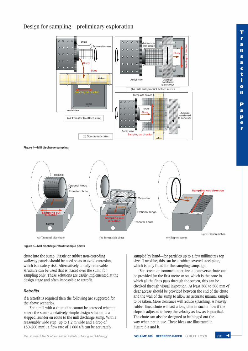
The design of many milling circuits make mill dischargestreams almost impossible to sample. Typically, trommel andscreen deck mill discharge set-ups are a serious impedimentto accurate sampling of the undersize product—although theyusually provide a good sampling and flow measurement (viarecycle) for oversize—provided good, safe access is includedat the design stage.
A transfer chute from the mill to the sump is easilyimplemented at design stage by offsetting the sump from themill. For a SAG and ball mill sharing a sump thisarrangement is standard. This allows the lip of the chute tobe sampled, Figure 4a. This can be applied to a trommel orscreen discharge.
For a screen discharge it is often not desired to changedirection, in which case the sump can be moved slightlyaway from the mill, and a transfer chute installed, Figure 4b.For discharge onto a screen, it is easiest to shift the screenforward, away from the mill, so that a short transfer chutecan be installed, Figure 4c. This allows the full mill product tobe sampled off a good launder. This has the added processbenefit of supplying a better distributed feed to the screen. Ithas been observed that generally less than half the length ofvibrating screens serving SAG/AG mill discharges is utilized,so the transfer chute can extend over the sump without lossof screening capacity.
For a SAG/AG mill with pebble ports it is inconvenientand difficult to sample the full mill product, as an outsizesample cutter is required. In this case it is preferable tosample the screen undersize. If it is not desired to offset thesump, as in Figure 4a, then a chute can be placed under thescreen and the lip allowed to overflow near the far end of thesump, ensuring that the stream, which has a low velocity,does not impact on the side of the chute, Figure 4c. Safeaccess over the side of the sump should provide an excellentstream within easy reach of a manual sample.
For all of these options, a non-corroding walkway shouldbe provided over or along the edge of the sump to allow forsafe manual sampling as the pulp flows over the lip of the
▲
700 OCTOBER 2006 VOLUME 106 REFEREED PAPER The Journal of The Southern African Institute of Mining and Metallurgy
Figure 3—Run-of-mine feed sampling
chute into the sump. Plastic or rubber non-corrodingwalkway panels should be used so as to avoid corrosion,which is a safety risk. Alternatively, a fully removablestructure can be used that is placed over the sump forsampling only. These solutions are easily implemented at thedesign stage and often impossible to retrofit.
Retrofits
If a retrofit is required then the following are suggested forthe above scenarios.
For a mill with a chute that cannot be accessed where itenters the sump, a relatively simple design solution is astepped launder en route to the mill discharge sump. With areasonably wide step (up to 1.2 m wide and a drop of150–200 mm), a flow rate of 1 000 t/h can be accurately
sampled by hand—for particles up to a few millimetres topsize. If need be, this can be a rubber covered steel plate,which is only fitted for the sampling campaign.
For screen or trommel undersize, a transverse chute canbe provided for the first metre or so, which is the zone inwhich all the fines pass through the screen, this can bechecked through visual inspection. At least 300 to 500 mm ofclear access should be provided between the end of the chuteand the wall of the sump to allow an accurate manual sampleto be taken. More clearance will reduce splashing. A heavilyrubber lined chute will last a long time in such a flow if theslope is adjusted to keep the velocity as low as is practical.The chute can also be designed to be hinged out the way when not in use. These ideas are illustrated in Figure 5 a and b.
Design for sampling—preliminary exploration
The Journal of The Southern African Institute of Mining and Metallurgy VOLUME 106 REFEREED PAPER OCTOBER 2006
Figure 5—Mill discharge retrofit sample points
Figure 4—Mill discharge sampling
(a) Trommel side chute (b) Screen side chute (c) Step on screenRajiv Chandramohan
chute
Trommel/screen
Aerial view
Sump
Sump
Aerial view
(a) Transfer to offset sump
(b) Full mill product before screen
(c) Screen undersize
Guide chutewith screen
Oversizetransferredto conveyor
Aerial view
Sump with screen
chute
Oversizetransferredto conveyor
Slurry
Slurry
Slurry
Slurry
Sampling cut direction
Sam
plin
g cu
t dire
ctio
n
Sampling cut direction
Trommel
Optional hinge
Optional hinge
Oversize
Sump
Sampling cutdirection
Slurry
Slurry
Slurry
Sampling cut direction
Sampling cutdirection
Transfer chute
Transfer chute
Transaction
Paper
701 ▲
Design for sampling—preliminary exploration
For a screen, where the sump is already too narrow forany sort of access, a blank horizontal section can sometimesbe fitted to the first 300–500 mm of screen to provide a 100 mm ‘step’ with a lip at which a representative manualcut can be taken, Figure 5c. This system can be employedwhen the screen area is underutilized, which is usually thecase for these mill discharge scalping screens.
SamplersOnce access has been provided, most of the streams can bemanually sampled. However, larger flows require an actuatedprimary sampler feeding into a launder, which can then bemanually sampled. A pneumatically driven, flow-through,primary cutter is usually the most practical for this task. Sucha cutter does not require additional headroom or need towithstand high inertial forces. Most commercial cuttersreverse the flow. A flow-through cutter experiences reduceddriving force and requires less restraining force. Thecollection launder can be placed well clear of the primaryflow.
Despite the higher up-front cost, commercial drivemechanisms will usually provide a lower total cost solutionthan in-house construction. There are many ways for suchdevices to be poorly designed so ongoing modifications andbreakdowns result in an overall higher cost and, moreimportantly, in non-availability or non-optimal (biased)samples. The lesson is that a reputable and experiencedsample manufacturer or supplier must be used.
Cyclone feed
A cyclone feed distributor provides a well-mixed zone, wellsuited to representative sampling. If at least one (andpreferably two) blank cyclone feed distributor outlets areprovided, one can be used to mount a probe type sampler.The probe diameter should be at least 3 times the diameter ofthe largest particle. The probe is inserted into the turbulentregion of the distributor. A length of hose is used to provideenough back pressure to match the pressure in the cyclones,to reduce the sample flow to something manageable, and toprovide an easy sample point.
Blanking off the overflow of a standby cyclone, andopening the feed to it for a brief period, provides a feedsample at the underflow. This works well, but has the
disadvantage of disturbing the circuit. This technique can beused to check the validity of the probe sampler, and thedepth of insertion of the probe adjusted if required.
Density and flow measurement on the vertical line to thedistributor should of course be standard practice. One trap tobe aware of is that high density minerals (such as sulphidesand magnetite) will concentrate in the circulating load andthe solids s.g. from the cyclone sample (not the mill feed)should be used for the circulating load flow rate. If the gradevaries widely, a grade model correction may be necessary foraccurate calibration of the density gauge.
Cyclone underflow
For a cluster of cyclones discharging into a launder, theoutlet from the launder can have a 300 mm step built into it.This step will provide an ideal sampling point for thecombined underflows. Access is provided via a hatch abovethe discharge outlet.
For neatness and to contain splashing, the underflowsare often sealed into a covered launder box. If this is thecase, then the lift-off covers must provide sufficient space forsampler access, Figure 7a. There needs to be sufficient spaceon either side of the spigot for a sample cutter to passthrough the whole stream into a clear area on either side.There also needs to be sufficient vertical space, at least
▲
702 OCTOBER 2006 VOLUME 106 REFEREED PAPER The Journal of The Southern African Institute of Mining and Metallurgy
Figure 6—Cyclone feed probe sampler
Figure 7—Cyclone underflow access
Cyclone distributor
Valves
Cleaning point
Sample pipe andpressure reduction
Sample
(a) Cover plate removed, revealing a roping cyclone (b) Good operator view and access
300 mm, below the spigot so that a cutter can fit under thecyclone. It should be noted that a large cutter width isrequired to receive the coarse cyclone underflow, and thisstream has a high velocity, thus a large volume is collected,typically 5 to 10 l. Many plants operate successfully, andcleanly, with open underflow troughs, Figure 7b. These arefavoured by the authors as they not only provide easysample access, but also, and more importantly, provide anexcellent visual measure of cyclone operation—as the flareangle of the underflow is sensitive to cyclone performance.The consequence of a hidden underflow is illustrated inFigure 7a, where a cyclone in a cluster is roping.
Cyclone overflow
This is usually provided with an auto-cutter, as it is animportant metallurgical accounting sample. If this is not thecase then the overflows must not be directed straight into apipe and on to a sump. It should be ensured that thecombined overflows pass through a suitable launder, witheasy access for manual sampling.
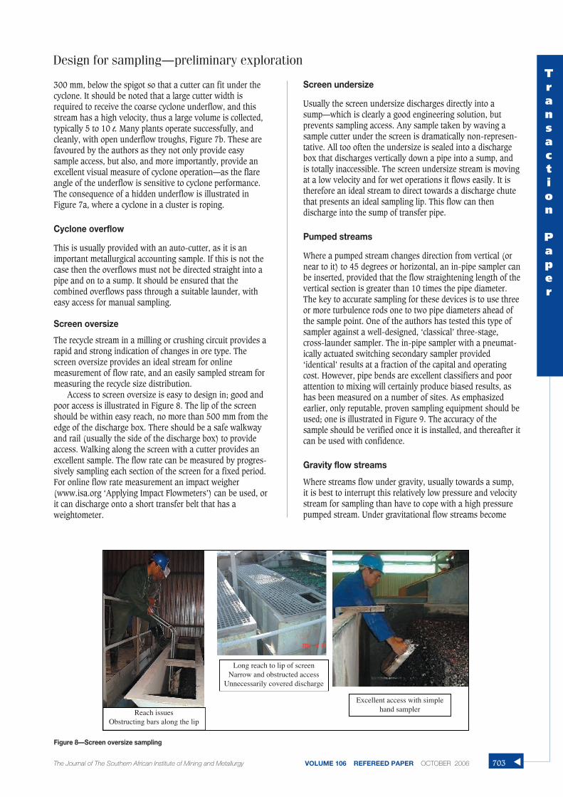
Screen oversize
The recycle stream in a milling or crushing circuit provides arapid and strong indication of changes in ore type. Thescreen oversize provides an ideal stream for onlinemeasurement of flow rate, and an easily sampled stream formeasuring the recycle size distribution.
Access to screen oversize is easy to design in; good andpoor access is illustrated in Figure 8. The lip of the screenshould be within easy reach, no more than 500 mm from theedge of the discharge box. There should be a safe walkwayand rail (usually the side of the discharge box) to provideaccess. Walking along the screen with a cutter provides anexcellent sample. The flow rate can be measured by progres-sively sampling each section of the screen for a fixed period.For online flow rate measurement an impact weigher (www.isa.org ‘Applying Impact Flowmeters’) can be used, orit can discharge onto a short transfer belt that has aweightometer.
Screen undersize
Usually the screen undersize discharges directly into asump—which is clearly a good engineering solution, butprevents sampling access. Any sample taken by waving asample cutter under the screen is dramatically non-represen-tative. All too often the undersize is sealed into a dischargebox that discharges vertically down a pipe into a sump, andis totally inaccessible. The screen undersize stream is movingat a low velocity and for wet operations it flows easily. It istherefore an ideal stream to direct towards a discharge chutethat presents an ideal sampling lip. This flow can thendischarge into the sump of transfer pipe.
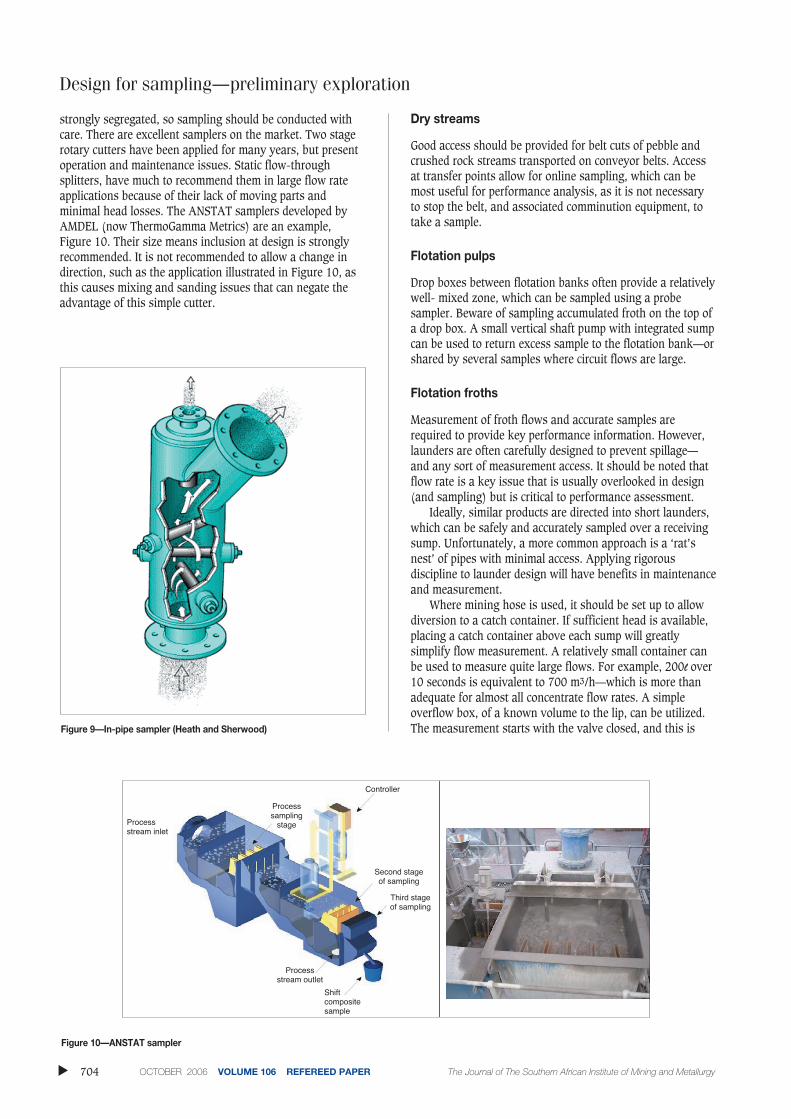
Pumped streams
Where a pumped stream changes direction from vertical (ornear to it) to 45 degrees or horizontal, an in-pipe sampler canbe inserted, provided that the flow straightening length of thevertical section is greater than 10 times the pipe diameter.The key to accurate sampling for these devices is to use threeor more turbulence rods one to two pipe diameters ahead ofthe sample point. One of the authors has tested this type ofsampler against a well-designed, ‘classical’ three-stage,cross-launder sampler. The in-pipe sampler with a pneumat-ically actuated switching secondary sampler provided‘identical’ results at a fraction of the capital and operatingcost. However, pipe bends are excellent classifiers and poorattention to mixing will certainly produce biased results, ashas been measured on a number of sites. As emphasizedearlier, only reputable, proven sampling equipment should beused; one is illustrated in Figure 9. The accuracy of thesample should be verified once it is installed, and thereafter itcan be used with confidence.
Gravity flow streams
Where streams flow under gravity, usually towards a sump,it is best to interrupt this relatively low pressure and velocitystream for sampling than have to cope with a high pressurepumped stream. Under gravitational flow streams become
Design for sampling—preliminary exploration
The Journal of The Southern African Institute of Mining and Metallurgy VOLUME 106 REFEREED PAPER OCTOBER 2006
Figure 8—Screen oversize sampling
Reach issuesObstructing bars along the lip
Long reach to lip of screenNarrow and obstructed access
Unnecessarily covered discharge
Excellent access with simplehand sampler
Transaction
Paper
703 ▲
Design for sampling—preliminary exploration
strongly segregated, so sampling should be conducted withcare. There are excellent samplers on the market. Two stagerotary cutters have been applied for many years, but presentoperation and maintenance issues. Static flow-throughsplitters, have much to recommend them in large flow rateapplications because of their lack of moving parts andminimal head losses. The ANSTAT samplers developed byAMDEL (now ThermoGamma Metrics) are an example,Figure 10. Their size means inclusion at design is stronglyrecommended. It is not recommended to allow a change indirection, such as the application illustrated in Figure 10, asthis causes mixing and sanding issues that can negate theadvantage of this simple cutter.
Dry streams
Good access should be provided for belt cuts of pebble andcrushed rock streams transported on conveyor belts. Accessat transfer points allow for online sampling, which can bemost useful for performance analysis, as it is not necessaryto stop the belt, and associated comminution equipment, totake a sample.
Flotation pulps
Drop boxes between flotation banks often provide a relativelywell- mixed zone, which can be sampled using a probesampler. Beware of sampling accumulated froth on the top ofa drop box. A small vertical shaft pump with integrated sumpcan be used to return excess sample to the flotation bank—orshared by several samples where circuit flows are large.
Flotation froths
Measurement of froth flows and accurate samples arerequired to provide key performance information. However,launders are often carefully designed to prevent spillage—and any sort of measurement access. It should be noted thatflow rate is a key issue that is usually overlooked in design(and sampling) but is critical to performance assessment.
Ideally, similar products are directed into short launders,which can be safely and accurately sampled over a receivingsump. Unfortunately, a more common approach is a ‘rat’snest’ of pipes with minimal access. Applying rigorousdiscipline to launder design will have benefits in maintenanceand measurement.
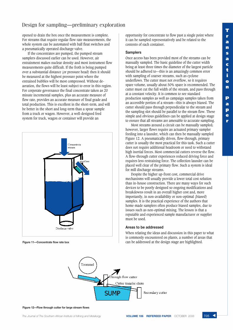
Where mining hose is used, it should be set up to allowdiversion to a catch container. If sufficient head is available,placing a catch container above each sump will greatlysimplify flow measurement. A relatively small container canbe used to measure quite large flows. For example, 200l over10 seconds is equivalent to 700 m3/h—which is more thanadequate for almost all concentrate flow rates. A simpleoverflow box, of a known volume to the lip, can be utilized.The measurement starts with the valve closed, and this is
▲
704 OCTOBER 2006 VOLUME 106 REFEREED PAPER The Journal of The Southern African Institute of Mining and Metallurgy
Figure 10—ANSTAT sampler
Controller
Processstream inlet
Processsampling
stage
Second stageof sampling
Third stageof sampling
Processstream outlet
Shiftcompositesample
Figure 9—In-pipe sampler (Heath and Sherwood)
opened to drain the box once the measurement is complete.For streams that require regular flow rate measurements, thewhole system can be automated with ball float switches anda pneumatically operated discharge valve.
If the concentrates are pumped, the pumped streamsamplers discussed earlier can be used. However, airentrainment makes nuclear density and most instrument flowmeasurements quite difficult. If the froth is being pumpedover a substantial distance (or pressure head) then it shouldbe measured at the highest pressure point where theentrained bubbles will be most compressed. Without de-aeration, the flows will be least subject to error in this region.For corporate governance the final concentrate taken as 20minute incremental samples, plus an accurate measure offlow rate, provides an accurate measure of final grade andtotal production. This is excellent in the short-term, and willbe better in the short and long-term than a spear samplefrom a truck or wagon. However, a well-designed feedsystem for truck, wagon or container will provide an
opportunity for concentrate to flow past a single point whereit can be sampled representatively and be related to thecontents of each container.
SamplersOnce access has been provided most of the streams can bemanually sampled. The basic guideline of the cutter widthbeing at least three times the diameter of the largest particleshould be adhered to—this is an amazingly common errorwith sampling of coarser streams, such as cycloneunderflows. The cutter must not overflow, so it requiresspare volume, usually about 50% spare is recommended. Thecutter must cut the full width of the stream, and pass throughat a constant velocity. It is common to see standardproduction samples as well as campaign samples taken froman accessible portion of a stream—this is always biased. Thecutter should pass through perpendicular to the stream andthe sampling slot should be parallel to the stream flow. Thesesimple and obvious guidelines can be applied at design stageto ensure that all streams are amenable to accurate sampling.
Most streams around a circuit can be manually sampled;however, larger flows require an actuated primary samplerfeeding into a launder, which can then be manually sampledFigure 12. A pneumatically driven, flow-through, primarycutter is usually the most practical for this task. Such a cutterdoes not require additional headroom or need to withstandhigh inertial forces. Most commercial cutters reverse the flow.A flow-through cutter experiences reduced driving force andrequires less restraining force. The collection launder can beplaced well clear of the primary flow. Such a system is idealfor mill discharge streams.
Despite the higher up-front cost, commercial drivemechanisms will usually provide a lower total cost solutionthan in-house construction. There are many ways for suchdevices to be poorly designed so ongoing modifications andbreakdowns result in an overall higher cost and, moreimportantly, in non-availability or non-optimal (biased)samples. It is the practical experience of the authors thathome-made samplers often produce biased samples, due toissues such as non-optimal mixing. The lesson is that areputable and experienced sample manufacturer or suppliermust be used.
Areas to be addressedWhen relating the ideas and discussion in this paper to whatis commonly encountered on plants, a number of areas thatcan be addressed at the design stage are highlighted.
Design for sampling—preliminary exploration
The Journal of The Southern African Institute of Mining and Metallurgy VOLUME 106 REFEREED PAPER OCTOBER 2006
Figure 11—Concentrate flow rate box
Figure 12—Flow through cutter for large stream flows
Transaction
Paper
705 ▲
Design for sampling—preliminary exploration
Metallurgical accounting➤ Ore source tracking➤ Feed moisture➤ Feed grade at circuit product➤ Concentrate grade and flowrate
➤ Mill product stream access– few plants know their actual mill densities
➤ Cyclone underflow– sample access on combined stream
➤ Screen oversize– sample access– flow rate via small transfer conveyor and
weightometer➤ Intermediate concentrate and flow rates (roughers)
Circuit optimization
➤ All gravity flow streams should have a stepped samplepoint– access to good manual sample– can install auto-cutter if desired– launder with rectangular lip and access at sump
entry➤ Cyclone feed
– take-off from spare point on distributor– pressure and flow reducing pipe
➤ Screen oversize– accessible for easy manual sample
➤ Flotation bank tails➤ Build in sample access points➤ Flotation concentrates
– give access– allow for flow rate measurement
Conclusions
For those who are designing a plant, beware of cost cutters.They are usually profit cutters in disguise. It is always worthconsidering whether there may be a more cost-effective wayto achieve an objective. Omission (or supposed delay) ofsampling and mass measurement equipment is not worthconsidering as organizational functionality is sacrificed. Thisequipment is an essential part of any plant.
Sampling and mass measurement are much more cost-effective if designed into the plant. Most of the suggestionsfor sample access that are presented in this paper can beincluded at almost no additional cost. In addition, suitableand safe access for operations and maintenance can beincluded at the same time.
It is usually not cost-(or time) effective to design your
own samplers. Well-designed samplers and measurementinstruments are certainly not cheap to purchase—but they areexorbitantly expensive to develop in an operating plant.Levering off the expertise and experience of establishedsuppliers is strongly recommended. (Ask their existingcustomers.)
Lastly, good, safe access to flows allows operators to ‘see’problems and to take samples when necessary.
Do1. Try to develop a strong measurement culture at a new
operation. This culture is very difficult to retrofit2. Provide access to each new stream.3. Provide flow rate measurement for key concentrate and
recycle streams. For slurries a simple timed cutter andweighed sample, linked in with a metallurgical samplethat is used for percent solids determination, isadequate
4. Shift equipment alignment to allow the insertion ofsampling points, there is no need to be locked intosymmetry
5. Allow streams to pass over launders, for accuratesampling
6. Make streams that give a visual cue to plant operationvisible, such as cyclone underflow and screen oversize
7. Firmly justify the need for sampling as an integral partof plant design, and ensure that the samplers are partof the engineering solution.
Don’t1. Direct pipes down into sumps leave the flow accessible 2. Use home-made samplers; save in the long-term by
purchasing well-proven samplers3. Sample and assay coarse samples where alternatives
are feasible4. Be bulldozed by cost cutters—they are mostly profit
cutters5. Let engineering design for convenience override
metallurgical requirements.
Acknowledgements
The authors would like to acknowledge the efforts of theresearch and consulting staff at the JKMRC and UCT and themany metallurgists, operators, and boilermakers who overthe years have assisted in modifying sample points to ourexacting requirements.
References
1. NAPIER-MUNN, T.J., MORRELL, S., MORRISON, R.D., and KOJOVIC, T. MineralComminution Circuits, Their operation and optimization, JuliusKruttschnitt Mineral Research Centre (JKMRC), University of Queensland,1996.
Some useful websites:
http://www.heathandsherwood64.com/mineral.html
www.wescone.com.au
www.isa.org
http://www.tema.net/products/sampling.html ◆
▲
706 OCTOBER 2006 VOLUME 106 REFEREED PAPER The Journal of The Southern African Institute of Mining and Metallurgy