91
Design Guidance for Construction Work Zones on High-Speed Highways Kevin M. Mahoney Penn State University
| Date post: | 04-May-2018 |
| Category: |
Documents |
| Upload: | truongcong |
| View: | 217 times |
| Download: | 2 times |
Design Guidance for
Construction Work Zones on
High-Speed Highways
Kevin M. Mahoney
Penn State University

Overview
� Scope of study
� Method
� Results

Overview
� Scope of study
�Method
�Results
Panel, NCHRP 3-69
James Kladianos, WY DOT
Russel Lenz, TX DOT
Herbert (Bert) Roy, NYS DOT
Robert Schlicht, FHWA
John Smith, MS DOT
Xiaoduan Sun, U of LA
J. Richard Young, PBSJ
Kenneth Opiela, FHWA
Frank Lisle, TRB
Charles Niessner, NCHRP
Michael Christensen, MnDOT (Retired) - Chair

Reviewers
James Brewer, KS DOT
Debbie Guest, LA DOTD
Mohammad Kahn, OH DOT
Glenn Rowe, PennDOT
Marcella Saenz, TX DOT
Norman Schips, NYS DOT
David Smith, NH DOT
Barbara Solberg, MD SHA
Marty Weed, WS DOT
Scott Zeller, WS DOT

Investigators
Kevin M. Mahoney, Penn State
Richard (R.J.) Porter, Penn State
Gerald L. Ullman, Texas Transportation Institute
Bohdan T. Kulakowski, Penn State

Overview
� Construction work zone:
.. area occupied for three or more days …
� High-speed highways:
… 85th percentile free-flow speed of 50 mph or greater
� Coverage:… information or guidance not available in another nationally referenced publication

Final Deliverable, NCHRP 3-69
� Research report (summary of methods)
� Hard copy appendix: Design Guidance � Dual units: Metric [US Customary]
� Green Book format and conventions
� CD: Work Zone Speed Prediction Model and User’s Manual

Design Guidance
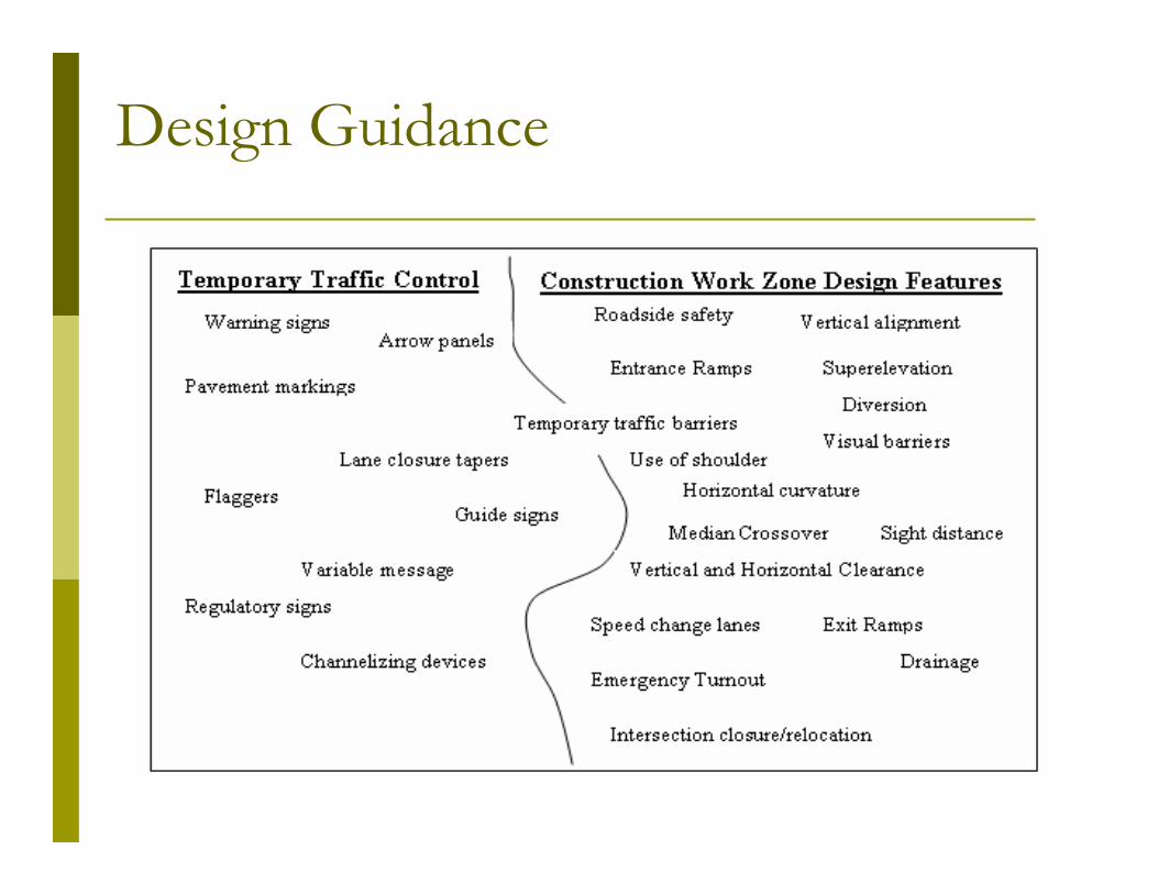
Design Guidance
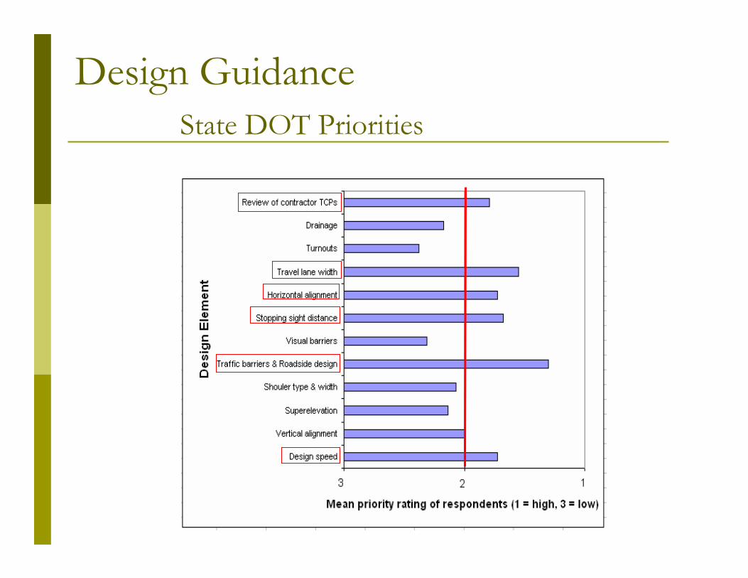
State DOT Priorities
Design Guidance

Design Guidance
� Guideline ….. not a standard
� Does not supersede “processes and criteria that have been implemented in an operational environment and carefully evaluated”
� Document alone cannot guide user to appropriate decision, must be applied by knowledgeable and experienced personnel
� “minimum” values identified selectively
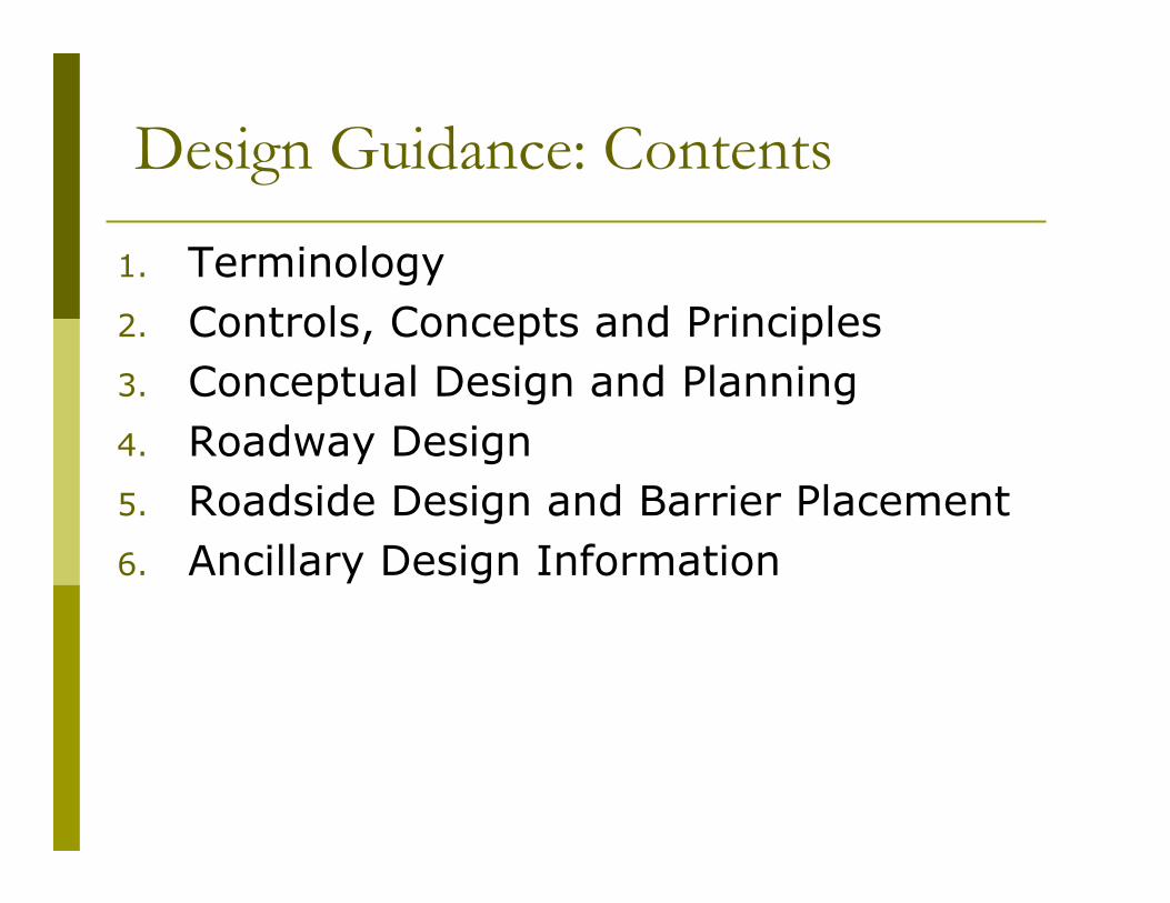
Design Guidance: Contents
1. Terminology
2. Controls, Concepts and Principles
3. Conceptual Design and Planning
4. Roadway Design
5. Roadside Design and Barrier Placement
6. Ancillary Design Information

Design Guidance: Contents
1. Terminology
2. Controls, Concepts and Principles
3. Conceptual Design and Planning
4. Roadway Design
5. Roadside Design and Barrier Placement
6. Ancillary Design Information

Design Controls and Principles
� Controls: “givens” that influence design
� Categories of controls� Human
� Materials
� Vehicles
� Setting
� Traffic
� Facility type
� Scope of project
� Generally similar to permanent road design

Principles
� Safety
� Design consistency
� Primacy
� Speed management
� Work zone design speed
� Sight distance
� Forgiving roadside
� Superelevation-horizontal alignment
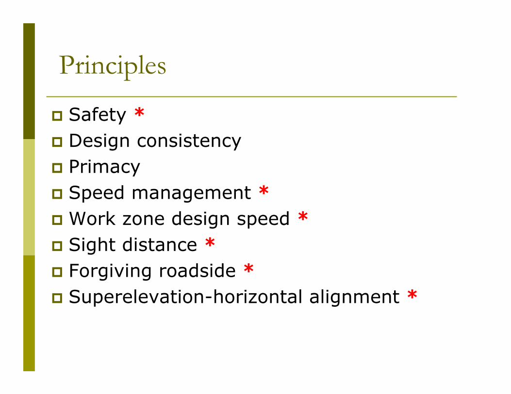
Principles
� Safety *
� Design consistency
� Primacy
� Speed management *
� Work zone design speed *
� Sight distance *
� Forgiving roadside *
� Superelevation-horizontal alignment *

Principles: Safety
� Substantive v. Nominal
� Function of exposure
� Use completed research, but …
� Many gaps in design-safety relationships

Principles: Speed Management
� Speed is controversial and prominent WZ topic
� Crash occurrence related to increased speed variance
� Basic speed management steps:
� Establish reasonable target speeds
� Employ measures to attain significant speed reductions
Identify and provide speed management measures
needed to attain significant
speed reduction.
Establish target speed based on constraints.
Determine pre-project operating and/or posted
speeds, approaching and
within construction area.
Establish target speed based
on approach speeds and pre-project conditions.
Establish work zone design
speed based on target speed. Design work zone.
Provide speed-related features and signing
appropriate for target speed.
Implement
All features
related to work
zone design speed are
feasible?
No
Yes
Pri
nci
ple
s: S
pee
d M
anag
emen
t

Principles: Sight Distance
� Previous research: in the SD ranges studied, limited SSD had no discernable effect on crash frequencies or rates. (NCHRP 400)
� One study: crash frequencies on crest vertical curves with SD less than 300 feet more than 50% higher than those with very long SD
� SD affects speed

Principles: Sight Distance
� Half of states responding to survey (16 of 32) do not apply stopping sight distance criteria to WZ design
� Recommended guidance: Provide at least 300 ft of SD with 3.5 ft eye height and 2.0 object height
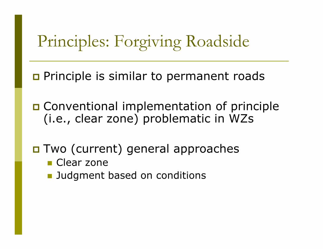
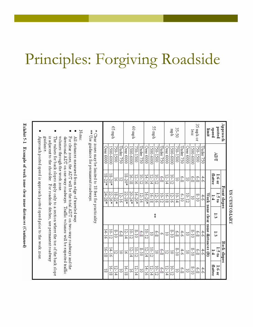
Principles: Forgiving Roadside
� Principle is similar to permanent roads
� Conventional implementation of principle (i.e., clear zone) problematic in WZs
� Two (current) general approaches� Clear zone
� Judgment based on conditions
Principles: Forgiving Roadside
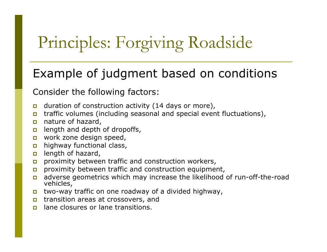
Example of judgment based on conditions
Consider the following factors:
� duration of construction activity (14 days or more),� traffic volumes (including seasonal and special event fluctuations),� nature of hazard,� length and depth of dropoffs,� work zone design speed,� highway functional class,� length of hazard,� proximity between traffic and construction workers,� proximity between traffic and construction equipment,� adverse geometrics which may increase the likelihood of run-off-the-road
vehicles,� two-way traffic on one roadway of a divided highway,� transition areas at crossovers, and� lane closures or lane transitions.
Principles: Forgiving Roadside

Guidance
� Summarizes current state DOT practice
� Barrier placement for common WZ scenarios
� Uses cost-effectiveness approach in RSAP to explicitly account for factors (e.g., duration, traffic, proximity)
� Details and results presented later
Principles: Forgiving Roadside

Green Book:
� Method 5 used for permanent roads:
� All rural (high speed, low speed)
� High-speed urban
� Method 2 used for low-speed urban streets
Principles: Superelevation-Horizontal Curvature
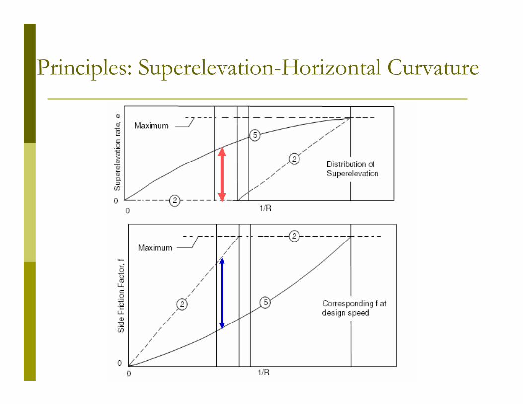
Principles: Superelevation-Horizontal Curvature

� Many DOTs indicated not having an established procedure for SE in WZs
� 8 DOTs use different SE approach for WZsthan permanent roads; 7 use Method 2 distribution
� Recommended guidance: Method 2 or 5
Principles: Superelevation-Horizontal Curvature

Design Guidance: Contents
1. Terminology
2. Controls, Concepts and Principles
3. Conceptual Design and Planning
4. Roadway Design
5. Roadside Design and Barrier Placement
6. Ancillary Design Information

Conceptual Design and Planning
� Identify alternatives
� Evaluate
� Agency cost
� User cost
� Non-cost impacts (e.g., emergency services, worker safety, local events)
� Select
� Detailed design in parallel with project

Conceptual Design and Planning

Conceptual Design and Planning

Conceptual Design and Planning
Screening two-lane road strategies
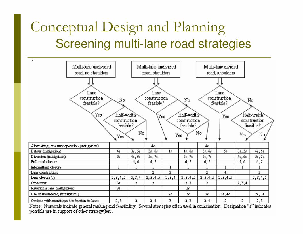
Conceptual Design and PlanningScreening multi-lane road strategies
Conceptual Design and Planning
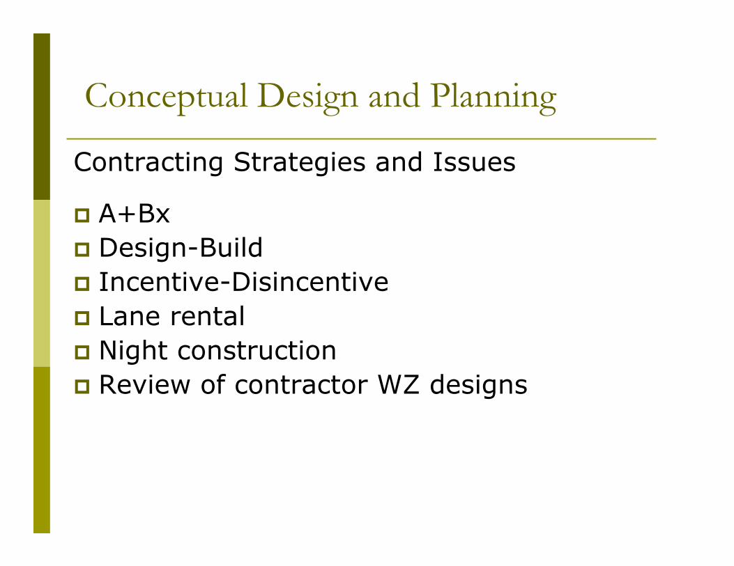
Contracting Strategies and Issues
� A+Bx
� Design-Build
� Incentive-Disincentive
� Lane rental
� Night construction
� Review of contractor WZ designs

Conceptual Design and Planning
Higher agency cost
Higher safety risks
Disrupts normal social patterns
of work force
Noise
Possible compromise in
construction quality
Lower traffic volumes and
lower traffic impacts
Lower impacts to commercial
activity
DisadvantagesAdvantages
Perceived Consequences of Night Work

Design Guidance: Contents
1. Terminology
2. Controls, Concepts and Principles
3. Conceptual Design and Planning
4. Roadway Design
5. Roadside Design and Barrier Placement
6. Ancillary Design Information

Roadway Design
� Some WZ strategies: TTC only
� Roadway design guidance
� Diversions
� Lane constriction
� Median crossover
� Use of shoulder
� Freeway interchange ramp

Roadway Design
√Use of shoulder
NA√√Median crossover
√ (minor road) Lane constriction
√√√Lane closure
√Intermittent closure
NA√Interchange ramp
Need detourNeed detourNeed detourFull road closure
√Diversion
√Detour
√√NAAt-grade intersections
√NANAAlternating one-way operation
Two-laneMulti-lane
non-freewayFreeway
MUTCD guidanceWork zone type, mitigation strategy
or element

Roadway Design
CCCB> 6000
CCBB1500 - 6000
CBBA500 - 1499
BBAA< 500
> 90 days31 – 90 days5 – 30 days< 5 days
Duration of operationCurrent ADT
Traveled Way Surface Type Guide
A = Aggregate or gravel
B = Aggregate or gravel with surface treatment
C = Design pavement structure

Roadway Design: Diversion
Example plan view

Roadway Design: Diversion
Example normal crown and superelevated sections

Roadway Design: Diversion
3624> 3000
30221000 – 3000
2622<1000
Roadway width
(ft)
Traveled way width
(ft)Current ADT
Recommended roadway and travel way widths

Roadway Design: Diversion
Other design decisions:
� Work zone design speed
� Superelevation-horizontal alignment
� Vertical� Max grades: functional class
� Crest: SD if applicable
� Sag curves: Comfort
� Roadside design
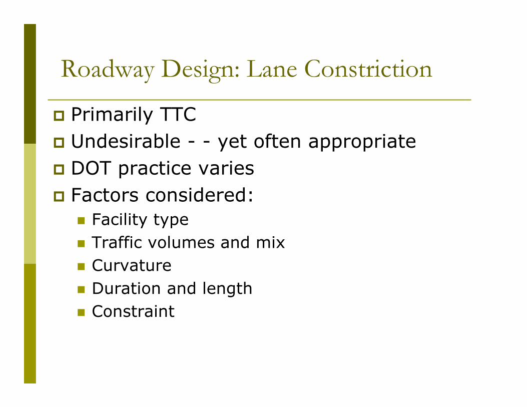
Roadway Design: Lane Constriction
� Primarily TTC
� Undesirable - - yet often appropriate
� DOT practice varies
� Factors considered:
� Facility type
� Traffic volumes and mix
� Curvature
� Duration and length
� Constraint

Roadway Design: Lane Constriction
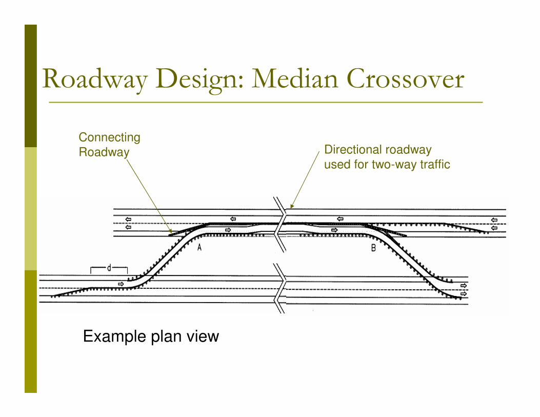
Roadway Design: Median Crossover
Example plan view
Connecting
Roadway Directional roadway
used for two-way traffic

Roadway Design: Median Crossover
Connecting Roadway
� Work zone design speed� Cross section
� Travel lane width: 12 – 16 ft; higher end of range recommended
� Shoulder width: 2 – 7 ft; symmetrical/asymmetrical
� Superelevation-horizontal alignment� Vertical
� Max grades: functional class; use lower values to maintain speed
� Crest: SD if applicable and speed� Sag curves: Comfort
� Barrier and roadside design

Roadway Design: Median Crossover
Directional Roadway
� Cross section allocation
� Asymmetrical
� Shoulder width and pavement
� Rumble strips
� Median and roadside design
� Separating directions of travel (covered later)
� “Trailing” bridge ends (covered later)
� Other roadside
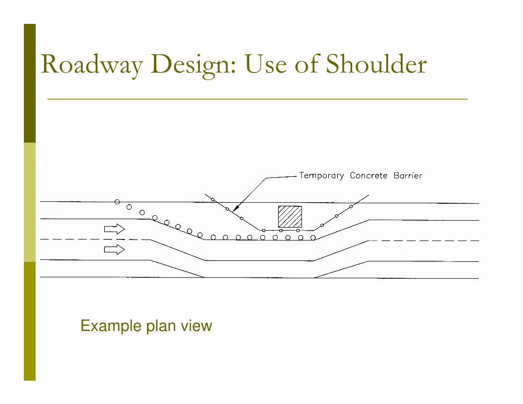
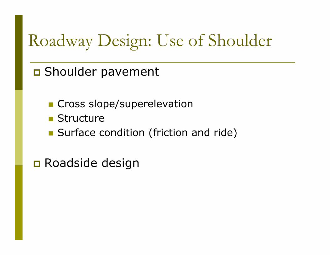
Roadway Design: Use of Shoulder
Example plan view
Roadway Design: Use of Shoulder
� Shoulder pavement
� Cross slope/superelevation
� Structure
� Surface condition (friction and ride)
� Roadside design

Roadway Design: Interchange Ramps
� Combination of TTC and geometry
� Entrance and exit ramps
� Temporary ramps (with crossovers)
� Minimum acceleration/deceleration lane lengths

Roadway Design: Interchange Ramps
Entrance Ramps: minimum acceleration lane lengths
� Most desirable: design criteria for permanent facilities
� Rules of thumb in use by DOTs:
� Minimum 300 feet
� 70% design criteria for permanent
� Traffic volumes (mainline and entrance ramp) and sight distance sometimes considered
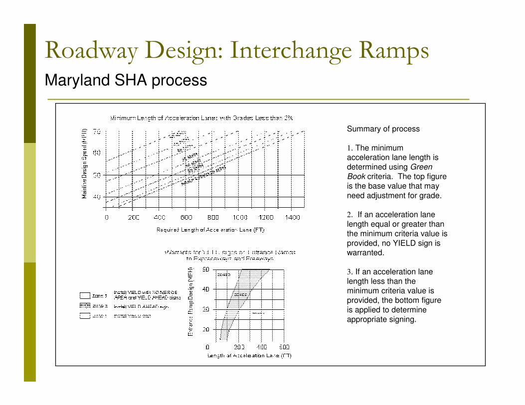
Summary of process
1. The minimum acceleration lane length is
determined using Green
Book criteria. The top figure
is the base value that may
need adjustment for grade.
2. If an acceleration lane
length equal or greater than
the minimum criteria value is
provided, no YIELD sign is warranted.
3. If an acceleration lane
length less than the minimum criteria value is
provided, the bottom figure
is applied to determine
appropriate signing.
Roadway Design: Interchange RampsMaryland SHA process

Roadway Design: Interchange Ramps

Roadway Design: Interchange Ramps
Cross section, entrance and exit
� Travel lane: 15 feet
� Shoulder:
� Right: 6 feet minimum
� Left: 2 feet minimum

Design Guidance: Contents
1. Terminology
2. Controls, Concepts and Principles
3. Conceptual Design and Planning
4. Roadway Design
5. Roadside Design and Barrier Placement
6. Ancillary Design Information
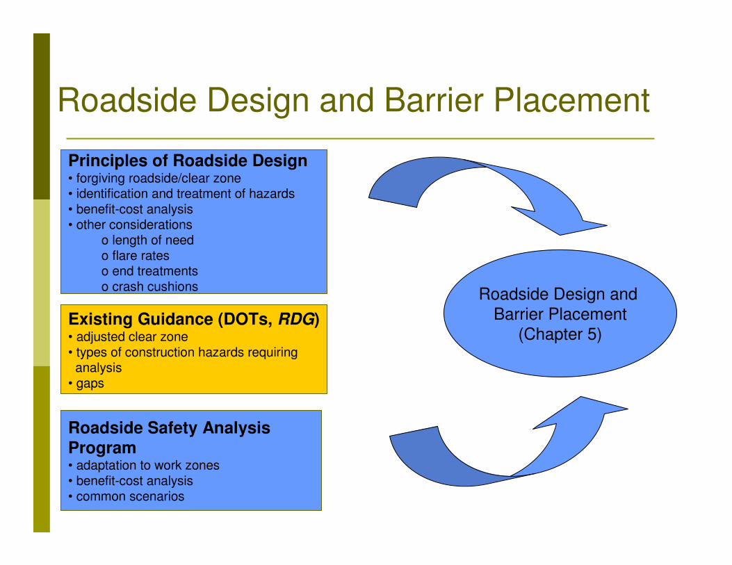
Principles of Roadside Design• forgiving roadside/clear zone• identification and treatment of hazards• benefit-cost analysis• other considerations
o length of needo flare rateso end treatmentso crash cushions
Roadside Safety Analysis Program• adaptation to work zones • benefit-cost analysis• common scenarios
Existing Guidance (DOTs, RDG)• adjusted clear zone • types of construction hazards requiring analysis
• gaps
Roadside Design and
Barrier Placement
(Chapter 5)
Roadside Design and Barrier Placement

Roadside Safety Analysis Program (RSAP)
� NCHRP Report 492
� Capable of cost-effectiveness analysis of roadside safety improvements
� Used for development of warrants and guidelines of safety features
� Adapted for construction work zones
Roadside Design and Barrier Placement

Adaptation of RSAP
Roadside Design and Barrier Placement

Severity Index vs. Impact Speed (Workers)
0
1
2
3
4
5
6
7
8
9
10
0 10 20 30 40 50 60 70
Impact Speed (mph)
Se
ve
rity
In
de
x
SI = 10
Average repair cost = $2000
Roadside Design and Barrier PlacementAdaptation of RSAP

Severity Index vs. Impact Speed (Light Equipment)
0
1
2
3
4
5
6
7
8
9
10
0 10 20 30 40 50 60 70
Impact Speed (mph)
Se
ve
rity
In
de
x
SI = 0.1143 * impact speed
Average repair cost = $4000
Roadside Design and Barrier Placement
Adaptation of RSAP
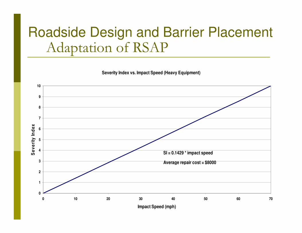
Severity Index vs. Impact Speed (Heavy Equipment)
0
1
2
3
4
5
6
7
8
9
10
0 10 20 30 40 50 60 70
Impact Speed (mph)
Se
ve
rity
In
de
x
SI = 0.1429 * impact speed
Average repair cost = $8000
Roadside Design and Barrier PlacementAdaptation of RSAP
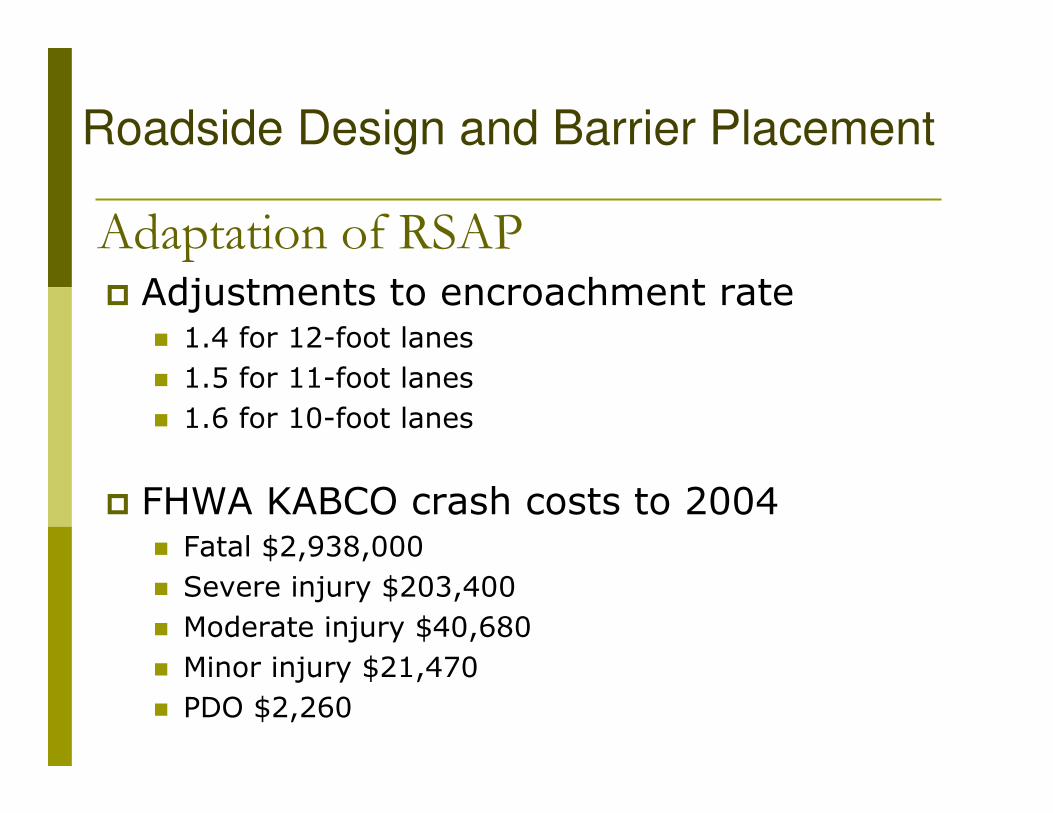
� Adjustments to encroachment rate� 1.4 for 12-foot lanes
� 1.5 for 11-foot lanes
� 1.6 for 10-foot lanes
� FHWA KABCO crash costs to 2004� Fatal $2,938,000
� Severe injury $203,400
� Moderate injury $40,680
� Minor injury $21,470
� PDO $2,260
Roadside Design and Barrier Placement
Adaptation of RSAP

� Installation Costs
� PCB $27/LF
� Guardrail $9/LF
� Temporary impact attenuator $4000/each
� Guardrail end treatment $600/each
� Repair Costs: vary by crash type
Roadside Design and Barrier Placement

Guidance for Generic Scenarios:
1. Right Lane and Shoulder Closure for Part-Width
Construction on a Four-Lane Divided Highway 2. Shoulder Closure on a Four-Lane Divided Highway with
Minor Encroachment
3. Median Work on a Four-Lane Divided Highway with Minor Encroachment
4. Bridge Reconstruction with Temporary Diversion/Runaround on a Two-Lane, Two-Way Highway
5. Separation of Two-Lane, Two-Way Traffic on a Normally Divided Facility (Results based on Ross & Sicking)
6. Protection of a Normally Downstream Barrier End for Two-
Lane, Two-Way Traffic on a Normally Divided Facility
Roadside Design and Barrier Placement

Roadside Design and Barrier Placement
Scenario 1: Shoulder Closure on a Four Lane
Divided Highway with Minor Encroachment

Generic Scenario 1: Shoulder Closure on a Four-Lane Divided Highway with Minor Encroachment
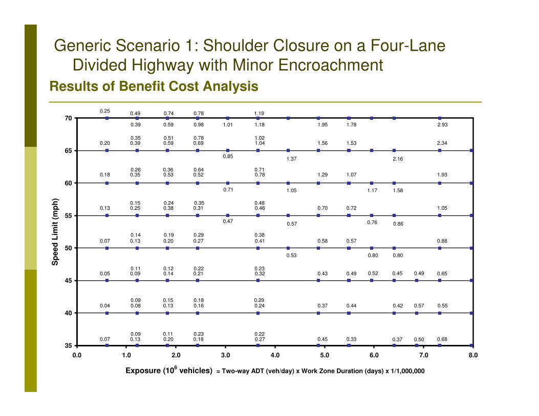
Results of Benefit Cost Analysis
35
40
45
50
55
60
65
70
0.0 1.0 2.0 3.0 4.0 5.0 6.0 7.0 8.0
Exposure (106 vehicles) = Two-way ADT (veh/day) x Work Zone Duration (days) x 1/1,000,000
Sp
ee
d L
imit
(m
ph
)
0.07 0.450.13
0.650.490.430.090.05
0.880.570.580.130.07
1.050.720.700.250.13
1.931.071.290.350.18
2.341.531.560.390.20
2.931.781.95
0.490.25
0.680.330.09
0.11
0.14
0.15
0.26
0.35
0.39
0.20
0.14
0.20
0.38
0.53
0.59
0.74
0.11
0.12
0.19
0.24
0.36
0.51
0.59
0.18
0.21
0.27
0.31
0.52
0.69
0.78
0.23
0.22
0.29
0.35
0.64
0.78
0.98
0.27
0.32
0.41
0.46
0.78
1.04
1.18
0.22
0.23
0.38
0.48
0.71
1.02
1.19
0.37
0.47
0.71
0.85
1.01
0.53
0.57
1.05
1.37
0.52
0.80
0.76
1.17
0.80
0.86
1.58
2.16
0.45 0.49
0.50
0.550.440.370.04 0.08 0.13 0.16 0.24 0.42 0.570.09 0.15 0.18 0.29
Generic Scenario 1: Shoulder Closure on a Four-Lane Divided Highway with Minor Encroachment

35
40
45
50
55
60
65
70
0.0 1.0 2.0 3.0 4.0 5.0 6.0 7.0 8.0
Exposure (106 vehicles) = Two-way ADT (veh/day) x Work Zone Duration (days) x 1/1,000,000
Sp
ee
d L
imit
(m
ph
)
B/C > 1.5
0.75 < B/C ≤ 1.5
0.25 < B/C ≤ 0.75
B/C ≤ 0.25
Generic Scenario 1: Shoulder Closure on a Four-Lane Divided Highway with Minor Encroachment
Results of Benefit Cost Analysis
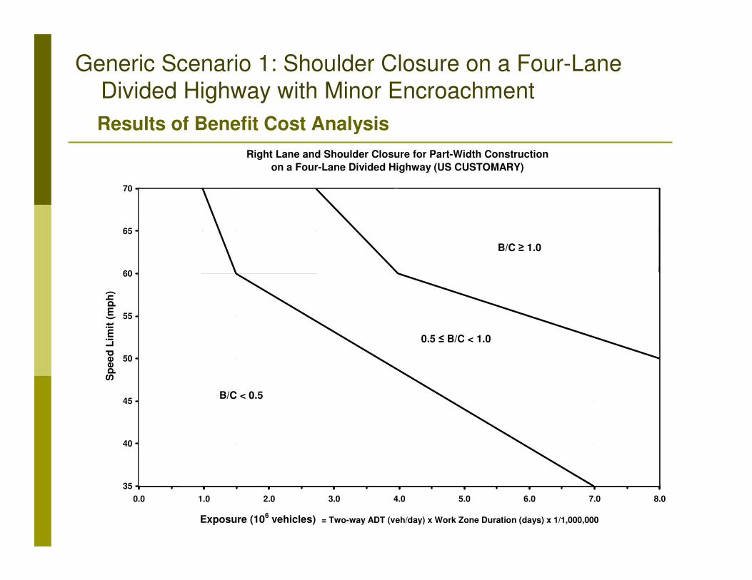
Right Lane and Shoulder Closure for Part-Width Construction
on a Four-Lane Divided Highway (US CUSTOMARY)
35
40
45
50
55
60
65
70
0.0 1.0 2.0 3.0 4.0 5.0 6.0 7.0 8.0
Exposure (106 vehicles) = Two-way ADT (veh/day) x Work Zone Duration (days) x 1/1,000,000
Sp
ee
d L
imit
(m
ph
)
0.5 ≤ B/C < 1.0
B/C < 0.5
B/C ≥ 1.0
Generic Scenario 1: Shoulder Closure on a Four-Lane Divided Highway with Minor Encroachment
Results of Benefit Cost Analysis
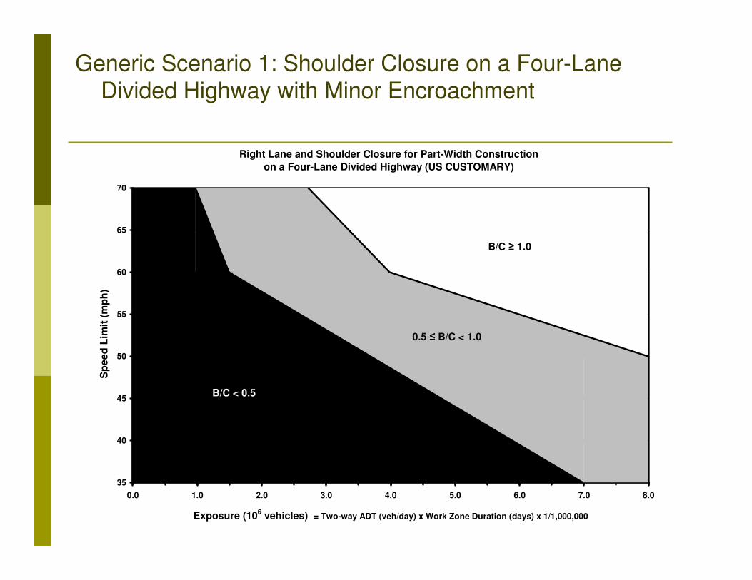
Right Lane and Shoulder Closure for Part-Width Construction
on a Four-Lane Divided Highway (US CUSTOMARY)
35
40
45
50
55
60
65
70
0.0 1.0 2.0 3.0 4.0 5.0 6.0 7.0 8.0
Exposure (106 vehicles) = Two-way ADT (veh/day) x Work Zone Duration (days) x 1/1,000,000
Sp
ee
d L
imit
(m
ph
)
0.5 ≤ B/C < 1.0
B/C < 0.5
B/C ≥ 1.0
Generic Scenario 1: Shoulder Closure on a Four-Lane Divided Highway with Minor Encroachment

Scenario 1 Design Guidance (Alternative 1): Language from AASHTO Subcommittee on Design with the Following Divisions
•Barrier recommended (B/C ratio ≥ 1.0)•Barrier recommended (see note) (0.5 ≤ B/C ratio < 1.0)Barrier not normally considered except in special circumstances (B/C ratio < 0.5)
35
40
45
50
55
60
65
70
0.0 1.0 2.0 3.0 4.0 5.0 6.0 7.0 8.0
Exposure (106 vehicles) = Two-way ADT (veh/day) x Work Zone Duration (days) x 1/1,000,000
Sp
eed
Lim
it (
mp
h)
Barrier recommended
(see note)Barrier not normally
considered except in
special circumstances
Barrier recommended
Note: States are encouraged to conduct a study to determine
whether or not a barrier is appropriate in these locations

Scenario 1 Design Guidance (Alternative 2): Language from AASHTO Subcommittee on Design with the Following Divisions• Barrier recommended (B/C ratio ≥ 2.0)• Barrier recommended (see note) (1.0 ≤ B/C ratio < 2.0)• Barrier not normally considered except in special circumstances (B/C ratio < 1.0)
35
40
45
50
55
60
65
70
0.0 1.0 2.0 3.0 4.0 5.0 6.0 7.0 8.0
Exposure (106 vehicles) = Two-way ADT (veh/day) x Work Zone Duration (days) x 1/1,000,000
Sp
eed
Lim
it (
mp
h)
Barrier
recommended
Barrier not normally
considered except in
special circumstances
Barrier recommended
(see note)
Note: States are encouraged to conduct a study to determine
whether or not a barrier is appropriate in these locations
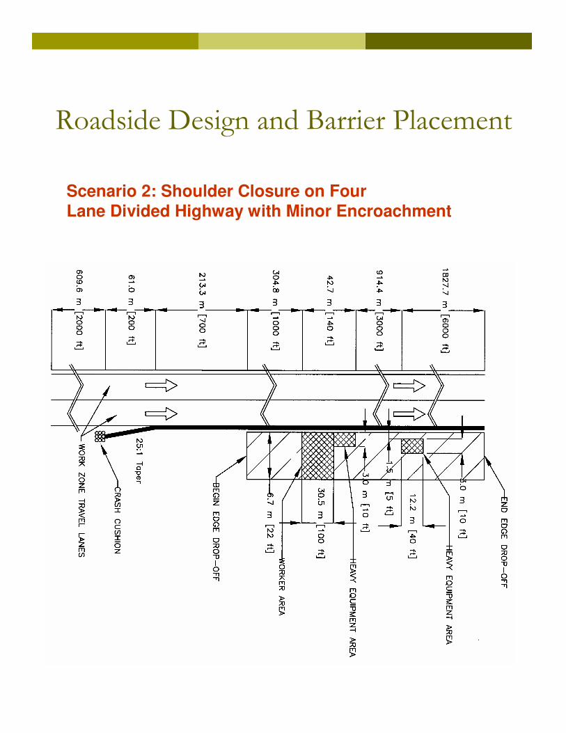
Roadside Design and Barrier Placement
Scenario 2: Shoulder Closure on FourLane Divided Highway with Minor Encroachment
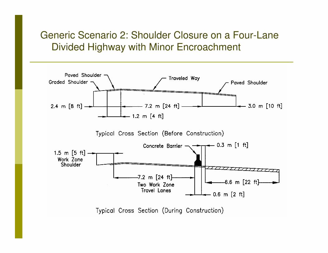
Generic Scenario 2: Shoulder Closure on a Four-Lane Divided Highway with Minor Encroachment
Roadside Design and Barrier Placement
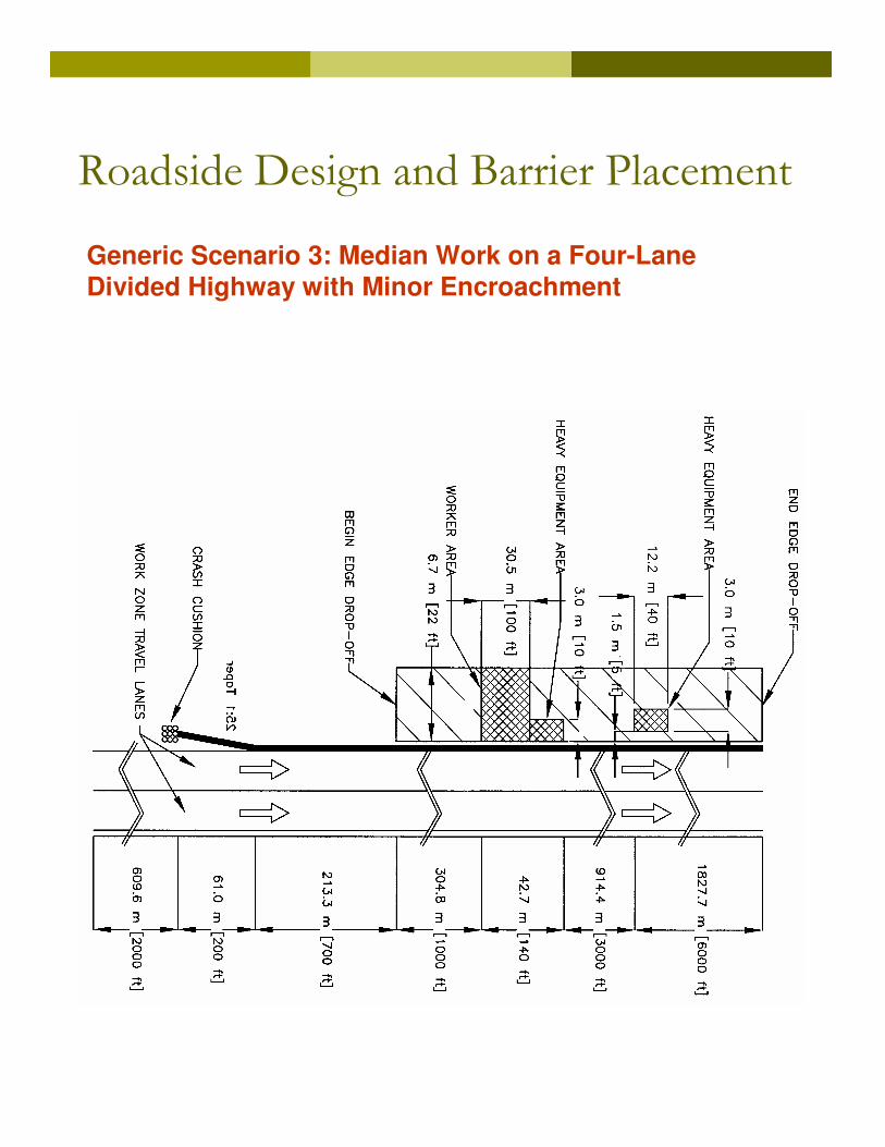
Generic Scenario 3: Median Work on a Four-Lane Divided Highway with Minor Encroachment
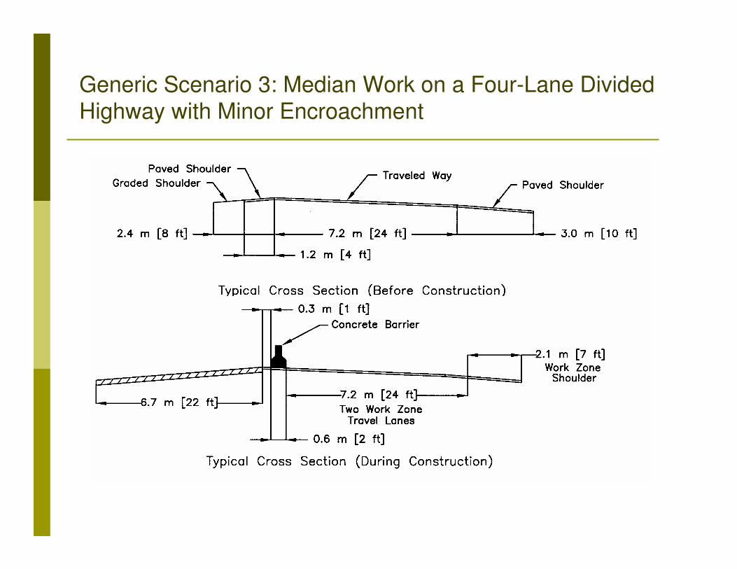
Generic Scenario 3: Median Work on a Four-Lane Divided Highway with Minor Encroachment

Roadside Design and Barrier Placement
Scenario 4: Bridge Reconstruction with Temporary Diversion/Runaround on a Two-Lane, Two-Way Highway

Generic Scenario 4: Bridge Reconstruction with Temporary Diversion/Runaround on a Two-Lane, Two-Way Highway

Carry barrier through or terminate?
Generic Scenario 5: Separation of Two-Lane, Two-Way Traffic on a Normally Divided Facility
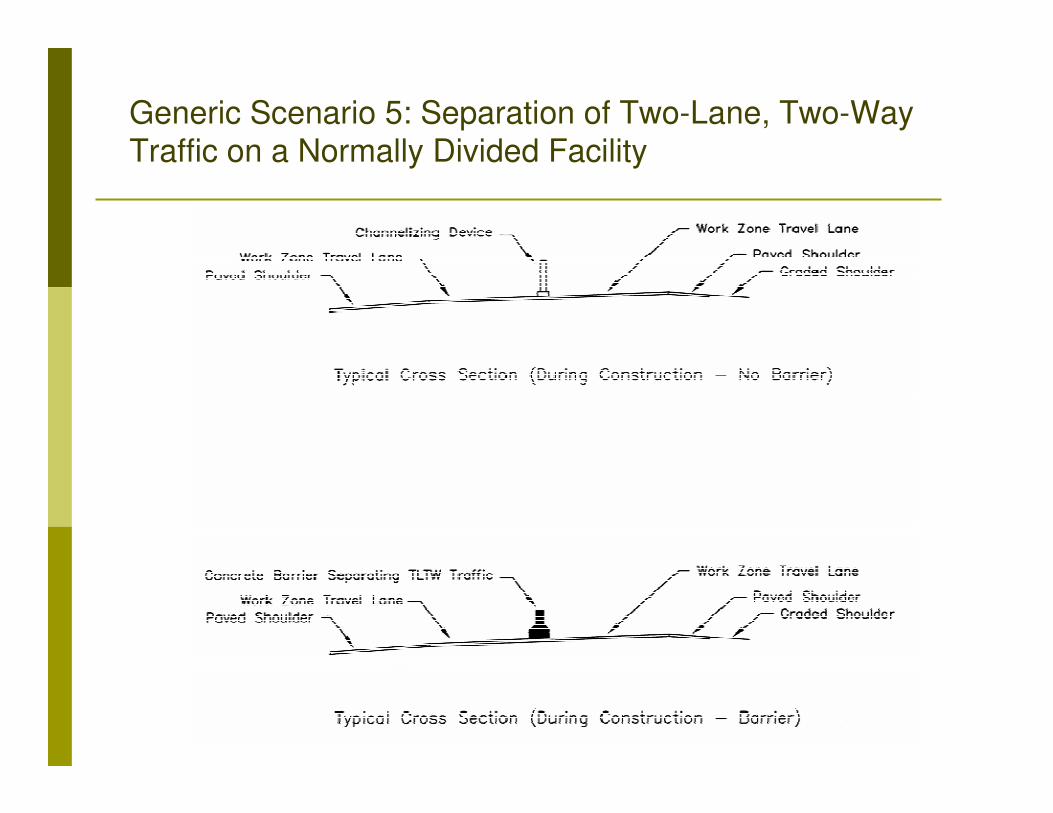
Generic Scenario 5: Separation of Two-Lane, Two-Way Traffic on a Normally Divided Facility
Roadside Design and Barrier Placement
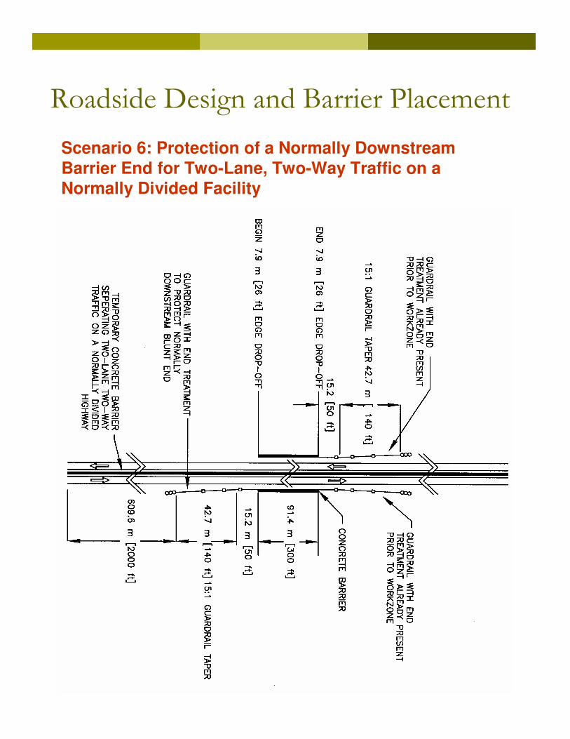
Scenario 6: Protection of a Normally DownstreamBarrier End for Two-Lane, Two-Way Traffic on aNormally Divided Facility

Roadside Design and Barrier Placement
Scenario 6: Protection of a Normally DownstreamBarrier End for Two-Lane, Two-Way Traffic on aNormally Divided Facility

Generic Scenario 6: Protection of a Normally Downstream Barrier End for Two-Lane, Two-Way Traffic on a Normally
Divided Facility

Generic Scenario 6: Protection of a Normally Downstream Barrier End for Two-Lane, Two-Way Traffic on a Normally
Divided Facility

Design Guidance: Contents
1. Terminology
2. Controls, Concepts and Principles
3. Conceptual Design and Planning
4. Roadway Design
5. Roadside Design and Barrier Placement
6. Ancillary Design Information

Ancillary Design Information
� Drainage
� Temporary bridges
� Emergency turnouts
� Screens *
� Portable Changeable Message Signs *
� Arrow Panels *
� Lighting *
� Rumble strips
* Primarily references MUTCD

Ancillary Design Information
Example: Emergency Turnout