YOU'RE HEARD, LOUD AND CLEAR. 8625 Industrial Parkway, Angola, NY 14006 Tel: 716-549-4700 Fax: 716-549-4772 [email protected]www.bird-technologies.com Manual Number 7-9500-2 Design Guide for the 428B TTA System
Transcript
TX RX Systems Inc. Manual 7-9500-2 08/31/10 Page 1
TX RX Systems Inc. Manual 7-9500-2 08/31/10 Page 2
Table of ContentsTower Top Amplifier (DS428B83H01T) .............................................................. 3Multicoupler Control Unit (DS428B83H01M)..................................................... 4Control Management Unit (DS428B83H01C)..................................................... 6Optional Narrowband Filter ................................................................................ 8MCU Expansion Deck (75-83H-428B).................................................................8Design Considerations .......................................................................................... 9Compatibility between 428 and 428B TTA System Components ........................10 General Discussion ...........................................................................................10 Identifying Your Tower Box .............................................................................13 Identifying your Base Deck..............................................................................13 Interchangeability ..............................................................................................13 Tower Top Boxes ............................................................................................14 428B Deck connected to a 428 Tower Box .....................................................14 428 Deck connected to a 428B Tower Box .....................................................14428 Expansion Deck Conversion .....................................................................15 Kit Contents .......................................................................................................15 Installation Procedure........................................................................................15Frequently Asked Questions............................................................................17Background material and other resources .....................................................18
TX RX Systems Inc. Manual 7-9500-2 08/31/10 Page 3
Design ComponentsTower Top Amplifier (DS428B83H01T) - The Tower Top Amplifier (TTA) uses aquad-amplifier design to overcome the losses of a long transmission line. A pair ofquad-amplifiers (A and B) are used in the tower box to provide redundancy. The 428BTower Top Amplifier box (Figure 1) is constructed of a polyester material to reduceweight while maintaining environmental integrity. A preselector is included in the towertop box with a 32 MHz bandwidth (792 to 824 MHz).
50
LNAA
Surge792-824Filter
AmpSelectSwitchA Term
SwitchB TermSwitch
ControlBoardCPU
AmpSelectSwitch
+12VDC+12VDC
3 dB
50
LNAB
SurgeRS-485 Tap
DC Tap
RS-485+12VDC
Antenna
Main Test
428BTTA Assembly
Figure 1: Picture and block diagram of the 428B TTA.
TX RX Systems Inc. Manual 7-9500-2 08/31/10 Page 4
Multicoupler Control Unit (DS428B83H01M) - The Multicoupler Control Unit(MCU) provides additional amplification to overcome the distribution loss of the multi-coupler (see Figure 2 and 3). The multicoupler has the ability to distribute to 16 receiv-ers and can be expanded to 32 with an additional shelf. The unit has adjustableattenuators for both reserve gain and distribution. Each amplifier assembly within thesystem is monitored to provide alarm indications. Form-C relay outputs are providedto interface to supervisory alarm systems. The standard unit is designed for 120 VACoperation but by adding 48 to the end of the part number (DS428B83H01M48) theunit will be designed for -48 VDC operation.
792-824 MHzFilter
A AlarmNC
COMNO
NC
COMNO
B Alarm
ModemDC Inject
CPU
FrontPanel
Assembly
Expansion Port
16 Way Divider
2 Way Divider
VariableAttenuator
VariableAttenuator
LNA
+12VDC
RS-485
+12VDCPowerSupply
Test Port
Main Test428B
MCU Assembly
Figure 2: MCU Picture and Block Diagram.
TX RX Systems Inc. Manual 7-9500-2 08/31/10 Page 5
MCU
Tower Top Box
MainTrans
TestPort
Antenna
TestPort
MainTransmission
StationReceivers
Surge protectors 6, 7, and 11 must be groundedto the Master Ground Buss.
MCU ground stud must be connected to theEquipment Rack Master Ground Bar.
Building entry-point ground plate andEquipment Rack Master Ground Barmust be grounded to Master Ground Buss.
GROUNDING REQUIREMENTSGROUNDING REQUIREMENTS
WARNING
Failure to ground the TTA System properly can resultin equipment failure caused by electrical surges.
1
1
1
1 1
1
6
7
5
13BNCTestPort
BuildingEntry-PointGroundPlate
CopperGround
Strap
FromRepeaters
10
511
18
1
2
2
2
2 2
2
4
4
4
2
TransmitCombiner
MCU
Master Ground Buss
Internal Perimeter Ground (Halo)
Tower TopAmplifier
Test MainAnt
RX TX
Entry-PointGround Buss
To ElectricalService Ground
Equipment RackMaster Ground Bar
Test
Main (RF In)
*
**
*
*
**
NOTE
Figure 3: Physical and Electrical Installation of MCU.
TX RX Systems Inc. Manual 7-9500-2 08/31/10 Page 6
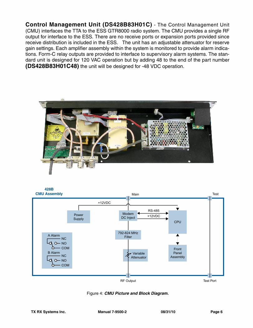
Control Management Unit (DS428B83H01C) - The Control Management Unit(CMU) interfaces the TTA to the ESS GTR8000 radio system. The CMU provides a single RFoutput for interface to the ESS. There are no receive ports or expansion ports provided sincereceive distribution is included in the ESS. The unit has an adjustable attenuator for reservegain settings. Each amplifier assembly within the system is monitored to provide alarm indica-tions. Form-C relay outputs are provided to interface to supervisory alarm systems. The stan-dard unit is designed for 120 VAC operation but by adding 48 to the end of the part number(DS428B83H01C48) the unit will be designed for -48 VDC operation.
792-824 MHzFilterA Alarm
NC
COMNO
NC
COMNO
B Alarm
ModemDC Inject
CPU
FrontPanel
AssemblyVariable
Attenuator
+12VDC
RS-485
+12VDCPowerSupply
Test PortRF Output
Main Test428B
CMU Assembly
Figure 4: CMU Picture and Block Diagram.
TX RX Systems Inc. Manual 7-9500-2 08/31/10 Page 7
CMU
Tower Top Box
MainTrans
TestPort
Antenna
TestPort
MainTransmission
Surge protectors 6, 7, and 11 must be groundedto the Master Ground Buss.
CMU ground stud must be connected to theEquipment Rack Master Ground Bar.
Building entry-point ground plate andEquipment Rack Master Ground Barmust be grounded to Master Ground Buss.
GROUNDING REQUIREMENTSGROUNDING REQUIREMENTS
WARNING
Failure to ground the TTA System properly can resultin equipment failure caused by electrical surges.
1
1
1
1 1
1
6
7
5
13 BNCTestPort
BuildingEntry-PointGroundPlate
CopperGround
Strap
FromRepeaters
10
511
18
1
2 2
2
2 2
2
4
4
4
2
TransmitCombiner
CMU
Master Ground Buss
Internal Perimeter Ground (Halo)
Tower TopAmplifier
Test MainAnt
RX TX
Entry-PointGround Buss
To ElectricalService Ground
Equipment RackMaster Ground Bar
Test
RF Out
Main (RF In)
*
**
*
*
**
NOTE
Figure 5: Physical and Electrical Installation of CMU.
TX RX Systems Inc. Manual 7-9500-2 08/31/10 Page 8
Remove ExistingCable 3-19152
Figure 6: Optional Narrowband Filter.
Figure 7: Optional Expansion Deck.
Optional Narrowband Filter - The nar-rowband filter is designed to help limit thebandwidth of the MCU style system. Thefilter is not used in CMU style systems.The option is shipped from the factory asshown in Figure 6 ready to be intercon-nected to the MCU deck. It is recom-mended that the optional filter be mountedin the same rack just above the MCU deck.There are a total of 9 different narrowbandfilters available as shown in the tablebelow.
OptionalFilter
Model #
OperatingRange (MHz)
Band-width(MHz)
89-83F-02-03 792 to 806 3
89-83F-02-06 792 to 806 6
89-83F-02-09 792 to 806 9
89-83F-02-14 792 to 806 14
89-86A-02-03 806 to 824 3
89-86A-02-05 806 to 824 5
89-86A-02-10 806 to 824 10
89-86A-02-15 806 to 824 15
89-86A-02-18 806 to 824 18
Optional Narrowband Filters.
MCU Expansion Deck (75-83H-428B) -The multicoupler expansion deck willincrease the total multicoupler outputs ofthe MCU style system to 32. The expan-sion deck is not used with the CMU stylesystem. The optional deck is shipped withthe required interconnect cables (asshown in Figure 7) and is designed to beinstalled in the same rack but below theMCU deck.
TX RX Systems Inc. Manual 7-9500-2 08/31/10 Page 9
Design ConsiderationsSurge Protectors – The 428B TTA system utilizes standard receive DC Pass surge protectors.These surge protectors must be provided by the engineer. The recommended surge arres-tors ( see Figure 8) from PolyPhaser are shown in Figure 3 and Figure 5 above and designated asitem 6, 7, and 11. Torquing specification obtained with proper Torque Wrenches is required toproperly tighten all connectors. See Torquing Initiative document for more information. The 109is an optimized arrestor with improved performance. The TSX protector is not only an optimizedprotector but also complies with our 150 dBc PIM and 25kW PIP requirements. All transmit pro-tectors will utilize 7-16 DIN connectors. The DSXL provides DC blocking and is only used inspecial cases where a 428 style tower top box is connected to a 428B style base deck. The useof this polyphaser is described on page 14.
Figure 8: PolyPhaser Surge Arrester Part Number and Picture.
Test Cable – The test cable connects the Control Unit with the TTA. This allows the TTA to betested from the bottom of the tower but emulates a signal at the input to the TTA. TheTest Cable should be constructed with LDF4 or equivalent ½” Heliax. Superflex cable isnever recommended for outside use. A surge protector must be installed at the exit tothe building.
Testing and Alignment – Testing the TTA system involves following the 5-Step procedure.The Reserve gain is adjusted according to the procedure. In the case of the MCU stylesystem the Distribution gain is also adjusted.
Standalone or interface to other radios – The MCU was designed to allow individual radios tobe connected to the TTA system. The ESS can also be utilized to interface externalreceivers and allow radio expansion outside the ESS.
DS1090501WA (N male to antenna) (N female to equipment)
DS1090501WB (N female to antenna) (N female to equipment)
Receive Cable andTest Port Protector
DSTSXDFMBF (DIN female / male)DSTSXDFFBF (DIN female / female)
Transmit Protector
DSDSXL (N female to antenna)(N female to equipment)
DSDSXLMA (N male to antenna)(N female to equipment)
DSDSXLME (N female to antenna)(N male to equipment)
DC Block for Test LineSpecial Cases Only (see page 14)
TX RX Systems Inc. Manual 7-9500-2 08/31/10 Page 10
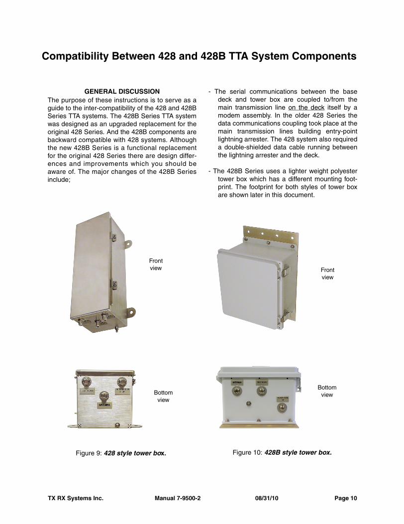
GENERAL DISCUSSIONThe purpose of these instructions is to serve as aguide to the inter-compatibility of the 428 and 428BSeries TTA systems. The 428B Series TTA systemwas designed as an upgraded replacement for theoriginal 428 Series. And the 428B components arebackward compatible with 428 systems. Althoughthe new 428B Series is a functional replacementfor the original 428 Series there are design differ-ences and improvements which you should beaware of. The major changes of the 428B Seriesinclude;
- The serial communications between the basedeck and tower box are coupled to/from themain transmission line on the deck itself by amodem assembly. In the older 428 Series thedata communications coupling took place at themain transmission lines building entry-pointlightning arrester. The 428 system also requireda double-shielded data cable running betweenthe lightning arrester and the deck.
- The 428B Series uses a lighter weight polyestertower box which has a different mounting foot-print. The footprint for both styles of tower boxare shown later in this document.
Compatibility Between 428 and 428B TTA System Components
Figure 9: 428 style tower box.
Frontview
Bottomview
Figure 10: 428B style tower box.
Frontview
Bottomview
TX RX Systems Inc. Manual 7-9500-2 08/31/10 Page 11
Figure 12: Top down view of the 428B MCU deck.
Modem Assembly
16-WayDivider
Assembly
If using DC Block (BLK -6+)add here
Figure 11: Top down view of the 428 MCU deck.
4-WayDivider
Assembly
8-WayDivider
Assemblies
TX RX Systems Inc. Manual 7-9500-2 08/31/10 Page 12
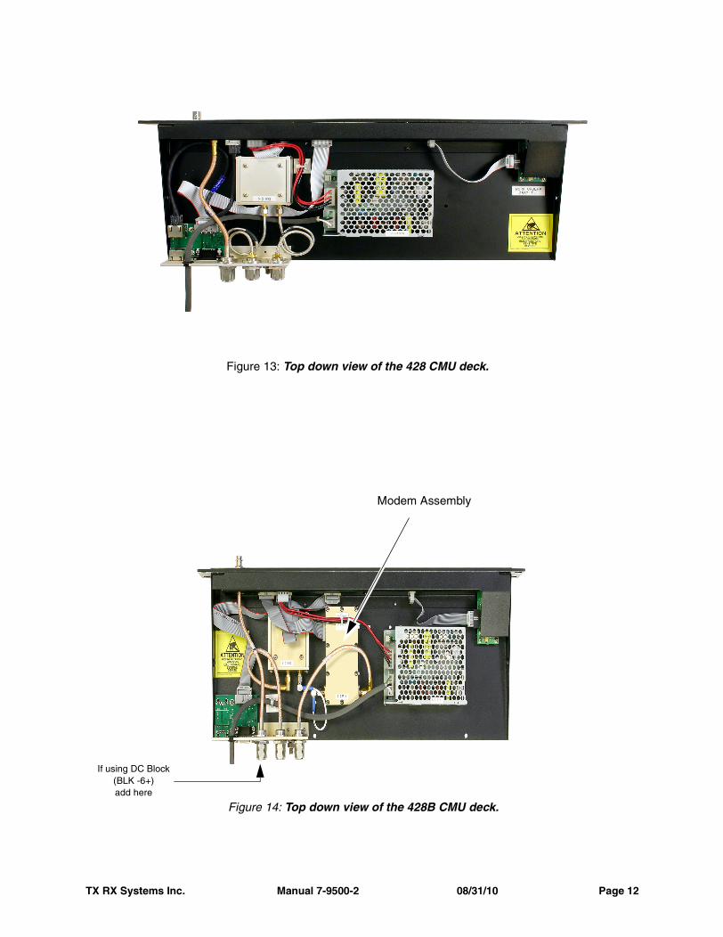
Figure 14: Top down view of the 428B CMU deck.
Modem Assembly
If using DC Block (BLK -6+)add here
Figure 13: Top down view of the 428 CMU deck.
1
- The test line coupling loss has been reduced inthe 428B Series down to 33.5 dB. This needs tobe taken into consideration when performingsensitivity tests as outlined in the installationand operation manual for your system.
- 428 series expansion decks (part# DDX1002A)need to be modified with a conversion kit whenconnecting them to a 428B deck.
Identifying Your Tower BoxIt’s easy to identify whether you have the 428 or428B tower box by a simple examination of thebox. The 428 system uses a tall stainless steel box(see Figure 9) while the 428B uses a rectangularpolyester box as shown in Figure 10.
Identifying Your Base DeckBase decks for both the 428 and 428B systems areavailable in two styles; either an MCU style or aCMU style. The difference between the MCU andCMU style is that the MCU style incorporates areceiver multicoupler on the deck and the CMUversion does not.
The front panels of both the 428 and 428B lookvery similar so in order to tell the difference you willneed to look at the deck from a top down angle.Figure 11 shows the 428 MCU deck and Figure12 shows the 428B MCU deck. The 428B MCUdeck will have a modem assembly and a 16-waydivider. The 428 MCU deck will not have a modemassembly and instead of a 16-way divider it willhave a pair of 8-way dividers along with a 4-waydivider.
Figure 13 shows the 428 CMU deck and Figure14 shows the 428B CMU deck. The 428B CMUdeck will have a modem assembly and the 428CMU deck will not. Notice that neither of the CMUstyle decks have any receiver multicoupler subas-semblies and therefore the decks are physicallysmaller than the MCU style decks.
INTERCHANGEABILITYAlthough there are some physical differencesbetween the 428B and 428 Series TTA systemsthey are functionally compatible. This compatibilityallows the tower box and deck from the two sys-tems to be interchanged. The instructions listedbelow will discuss in detail the interchangeability ofthe decks and tower boxes.
Mounting Tabs
.312 Dia ThruMount Holes4 Places
7.125"
2.00"
1.0
1.0
16.0
2.667 2.667 2.667 .453 thru8 places
Figure 15: Tower top box mechanical details.
428 style box
428B style box
TX RX Systems Inc. Manual 7-9500-2 08/31/10 Page 13
Tower Top BoxesThe tower top boxes are the easiest components ofyour TTA system to interchange. You simply needto move the three RF cables from your existing boxand re-connect them to similarly labeled connec-tors on the new box. Keep in mind that there areconsiderable differences in the mounting holedimensions between the 428 and 428B seriestower boxes. Refer to Figure 15 which shows themechanical details of each box style and Figure 16which shows the main transmission line connec-tions of both 428 and 428B series systems.
428B Deck connected to a 428 Tower BoxWhen connecting a 428B deck to a 428 tower boxthe following notes apply;
- There is no need to use the specia l izedpolyphaser/modem (TXRX part number 8-21550).Also, there is no need to use the data protectors(Polyphaser part # NX3-05) or the data cable thatruns between the polyphaser and the deck.
- The customer must supply and install a serialpass and DC pass polyphaser at the main trans-mission line building-entry point. Use Motorola part
number DS1090501W-A (Male/Female) or partnumber DS1090501W-B (Female/Female).
- The 428 tower box places a DC voltage on thetest transmission line. On the 428B deck the frontpanel test connector is straight-through connectedto the rear panel test connector. So when a 428Bdeck is connected to a 428 tower top box the testline DC voltage will now be present on the decksfront panel BNC test connector. To block this DCvoltage you can install a DC Block on the decksrear panel test connector or you can change thebuilding entry-point surge suppressor to a DCblocking type. If you use a DC Block on the rear ofthe deck use Mini-Circuits part number “BLK-6+”(see figures 12 or 14). If you use a DC blockingtype surge arrester at the building entry-point useMotorola part number “DSDSXL” (female/female)or “DSDSXLMA” (male/female).
428 Deck connected to a 428B Tower BoxWhen connecting a 428 deck to a 428B tower boxthe following notes apply;
- The 428B tower box does not place a DC voltageon the test transmission line. The 428 deck will
Tower Box Tower Box
428 428B
MainTransmission
Line
MainTransmission
Line
LightningArrester8-21550
LightningArrester
DS1090501W-Aor
DS1090501W-BData ProtectorDSNX305
428Base Deck
428BBase Deck
Building Entry Point
Figure 16: Main Transmission Line connections of the 428 and 428B series systems.
TX RX Systems Inc. Manual 7-9500-2 08/31/10 Page 14
interpret this as a fault and will display a “test cablenot connected” message on the LCD display.
If you have an older version of firm-ware in your 428 deck you will alsosee the front panel BASE LED turnred. You should update your 428 deckfirmware to version 1.72 or later. This
software upgrade will eliminate the “test cable notconnected” message and the red LED.
428 EXPANSION DECK CONVERSIONThe DDX1002A is an expansion deck designed toexpand the number of RF output ports on the 428series TTA deck (see Figure 17). These instruc-tions describe the installation of a conversion kit forthe DDX1002A expansion deck. The purpose ofthe conversion is to allow the DDX1002A to beused as an expansion deck for the model 428Bseries TTA deck.
The kit (TXRX part # 75-90-428) contains all thenecessary parts as listed below.
Kit Contents(2) 4-40 x 1/4” screws (TXRX part # 8-6003)(1) BNC-BNC cable (TXRX part # 3-14536)(1) 2-way Power Divider (TXRX part # 3-17107)
Installation ProcedureThe installation procedure is very straight forwardand consists of mounting a 2-way divider on thedeck and connecting cables between the sub-assemblies. Follow the procedure below in a step-by step fashion to complete the conversion.
1) Place the supplied 2-way divider on the deck inbetween the existing 8-way dividers with theBNC connectors facing inwards towards thedeck (see Figure 18).
2) While holding the 2-way divider in place standthe deck up on its edge and install two 4-40screws in the mounting holes shown in Figure19.
3) Lay the deck down flat and install the threecables to the individual dividers as shown inFigure 20.
4) The free end of the cable attached to the centerconnector on the 2-way divider will be used toconnect to the expansion port on the 428B con-trol unit deck.
NOTE
Figure 17: The DDX1002A Expansion Deck.
TX RX Systems Inc. Manual 7-9500-2 08/31/10 Page 15
TX RX Systems Inc. Manual 7-9500-2 08/31/10 Page 16
Figure 18: Placing the 2-way divider.
Figure 19: Install the 2-way mounting screws.
Figure 20: DDX1002A Expansion Deck with conversion kit installed.
TX RX Systems Inc. Manual 7-9500-2 08/31/10 Page 17
Frequently Asked Questions (FAQ)
Q – Can the ESS supply distribution to other radios outside the ESS cabinet?
A – Yes. The signal is taken from one of the unused ports on the Site RMC and distributed to other radios. Careful adjustment of gain must be considered and balanced sensitivity must be veri-fied after installation. Distribution power splitting must be done with separate Power splitting.
Q – Can an ESS cabinet be fed from an MCU?
A – Yes. When the ESS is connected to the MCU there must be an additional 3 dB attenuator installed between the MCU and ESS to balance the extra amplification in the ESS.
Q – Should the unused ports on the MCU be terminated?
A – No. Internal splitters maintain isolation without the need for external termination. However, unused expansion ports must be externally terminated.
Q – Can the 428B TTA, MCU, or CMU be ordered and used on a 428 TTA receive system?
A – Yes. Review the compatibility section of this guide for changes and modifications that are required.
Q – Is the PolyPhaser for the main receive line the same as the one used on the current 428 TTA?
A – No. The PolyPhaser surge protector used in the 428 contains a data modem to combine telemetry data on the RF line. The new TTA does not require a separate data line because the data is applied directly to the RF cable.
Q – Is the Surge Protector used on the receive line included with the TTA?A – No. The new TTA combines the data within the Control Unit and does not require a datamodem. For this reason the responsibility of supplying the surge protector falls on Motorola. Theengineer must include the receive line surge protector in their design.
TX RX Systems Inc. Manual 7-9500-2 08/31/10 Page 18
Bryan Corley
Bryan Corley Principal Staff Engineer
M otorola, Inc 12515 Saracen Cypress, TX 77429 U.S.A.
Background Material and other resources428B Design Guidehttp://compass.mot.com/doc/351239875/Design_Guide_of_ 428B_TTA_System_version_1.0.pdfDesign Guide for the 428B Family of receive amplifier components. This guide is aimed at answering most questions during the design phase.
428B TTA marketing sheethttp://compass.mot.com/doc/351239876/428B_Marketing_Sheet_4142010_.pdfBTG (TxRx) marketing sheet containing the detailed technical specifications on the 428B.
428B TTA Manual http://compass.mot.com/doc/351239874/428B_Manual_7-9487.pdfBTG (TxRx) manual detailing all of the information required to install, optimize, and troubleshoot the 428B TTA.
5 Step Program for Receiver Multicoupler verificationhttp://compass.mot.com/doc/351187695/Five_Step_Program_v7_0.pdfThis document describes the test procedure for testing, aligning, and troubleshooting TTA systems. This document should be used for every TTA acceptance test plan.
For more information or for additional assistance please contact:
Don HustonBird Technologies GroupMotorola Account Manager& Technical Trainer