Channels 7.9-1 October 2000 ConnDOT Drainage Manual 7.9 Design Guidelines – Rock Riprap 7.9.1 Rock Riprap This section contains design guidelines for the design of rock riprap. Guidelines are provided for bank slope, rock size, rock gradation, riprap layer thickness, filter design, edge treatment and construction considerations. In addition, typical construction details are illustrated. In most cases, the guidelines presented apply equally to rock and rubble riprap. Guidelines for other types are presented in HEC-11. 7.9.2 Bank Slope A primary consideration in the design of stable riprap bank protection schemes is the slope of the channel bank. For riprap installations, normally the maximum recommended face slope is 1V:2H. 7.9.3 Rock Size The stability of a particular riprap particle is a function of its size, expressed either in terms of its weight or equivalent diameter. In the following sections, relationships are presented for evaluating the riprap size required to resist particle and wave erosion forces. 7.9.4 Particle Erosion Two methods or approaches have been used historically to evaluate a material's resistance to particle erosion. These methods are the permissible velocity approach and the permissible tractive force (shear stress) approach. Under the permissible velocity approach the channel is assumed stable if the computed mean velocity is lower than the maximum permissible velocity. The tractive force (boundary shear stress) approach focuses on stresses developed at the interface between flowing water and materials forming the channel boundary.
Transcript
Channels 7.9-1
October 2000 ConnDOT Drainage Manual
7.9 Design Guidelines – Rock Riprap
7.9.1 Rock Riprap
This section contains design guidelines for the design of rock riprap. Guidelines are providedfor bank slope, rock size, rock gradation, riprap layer thickness, filter design, edge treatment andconstruction considerations. In addition, typical construction details are illustrated. In most cases,the guidelines presented apply equally to rock and rubble riprap. Guidelines for other types arepresented in HEC-11.
7.9.2 Bank Slope
A primary consideration in the design of stable riprap bank protection schemes is the slope ofthe channel bank. For riprap installations, normally the maximum recommended face slope is1V:2H.
7.9.3 Rock Size
The stability of a particular riprap particle is a function of its size, expressed either in terms of itsweight or equivalent diameter. In the following sections, relationships are presented for evaluatingthe riprap size required to resist particle and wave erosion forces.
7.9.4 Particle Erosion
Two methods or approaches have been used historically to evaluate a material's resistance toparticle erosion. These methods are the permissible velocity approach and the permissible tractiveforce (shear stress) approach. Under the permissible velocity approach the channel is assumedstable if the computed mean velocity is lower than the maximum permissible velocity. The tractiveforce (boundary shear stress) approach focuses on stresses developed at the interface betweenflowing water and materials forming the channel boundary.
7.9-2 Channels
ConnDOT Drainage Manual May 2002
7.9.5 Design Relationship
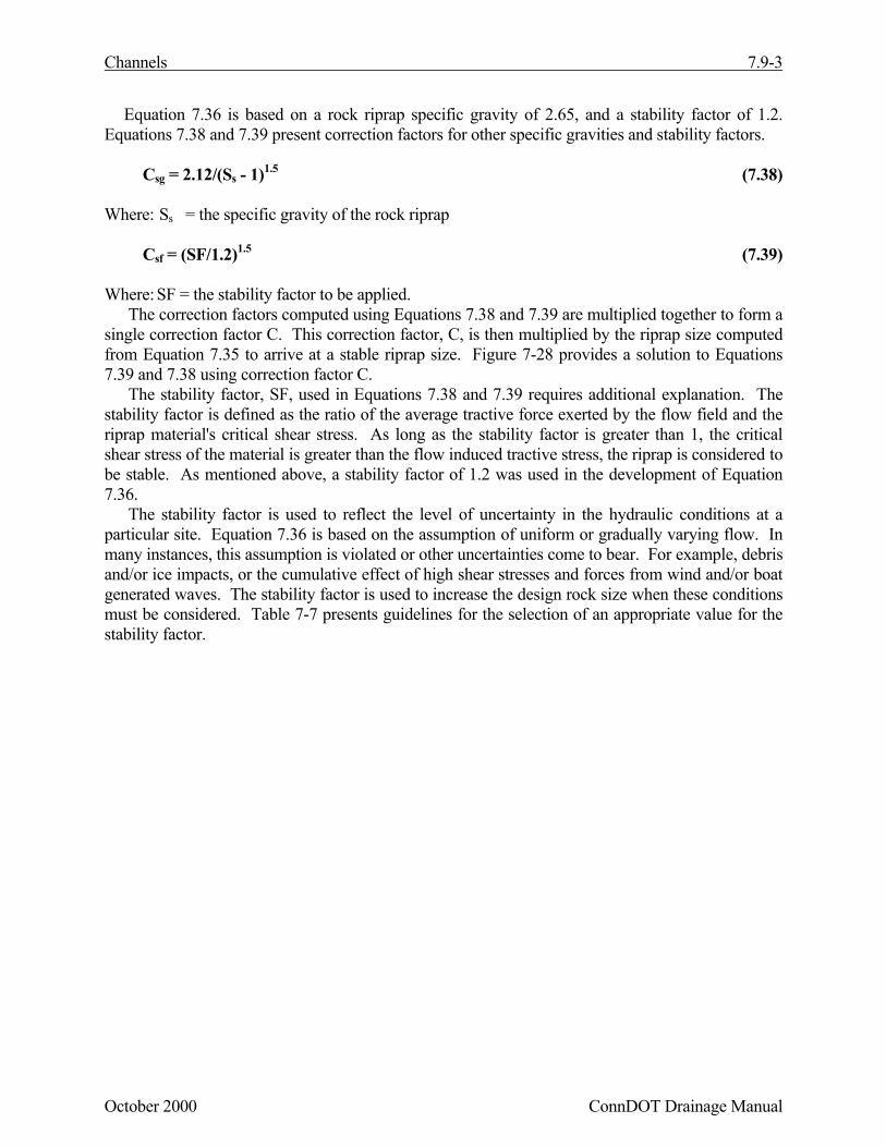
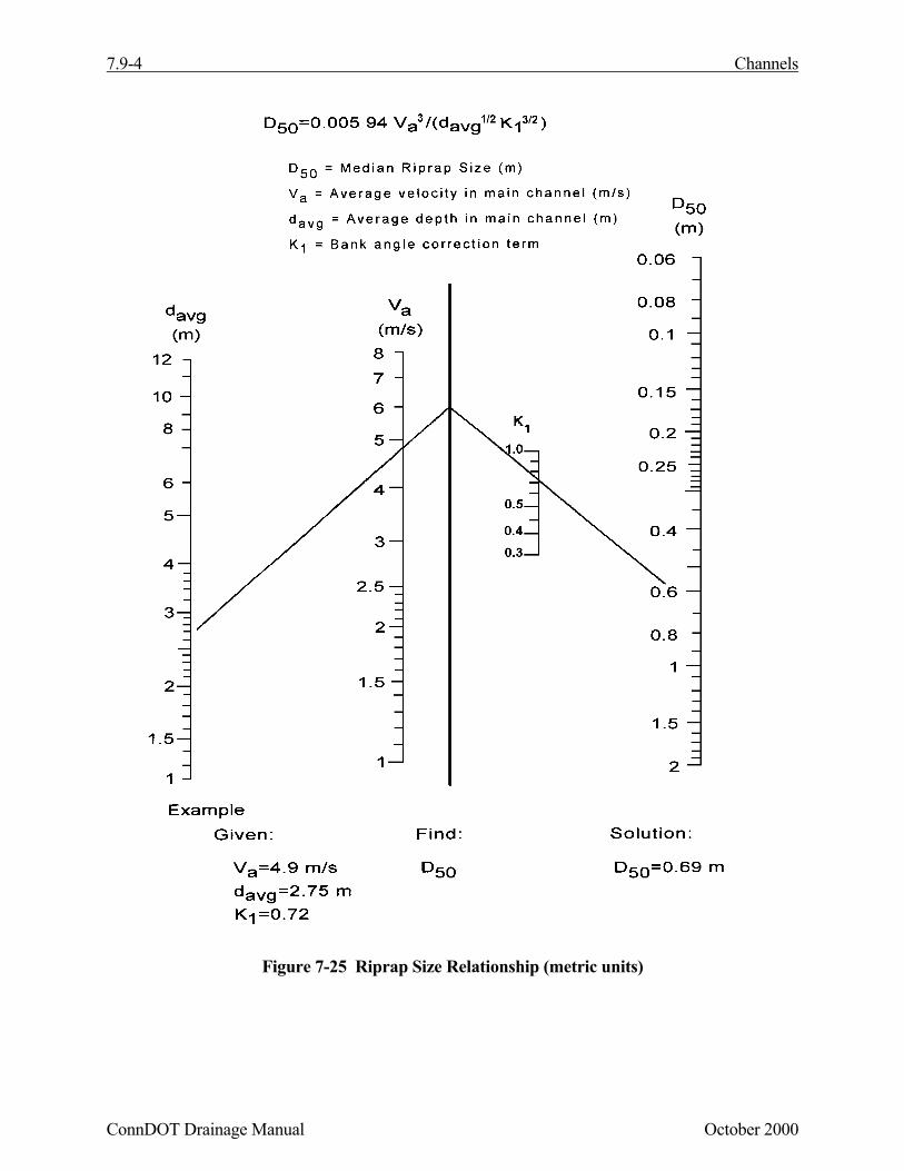
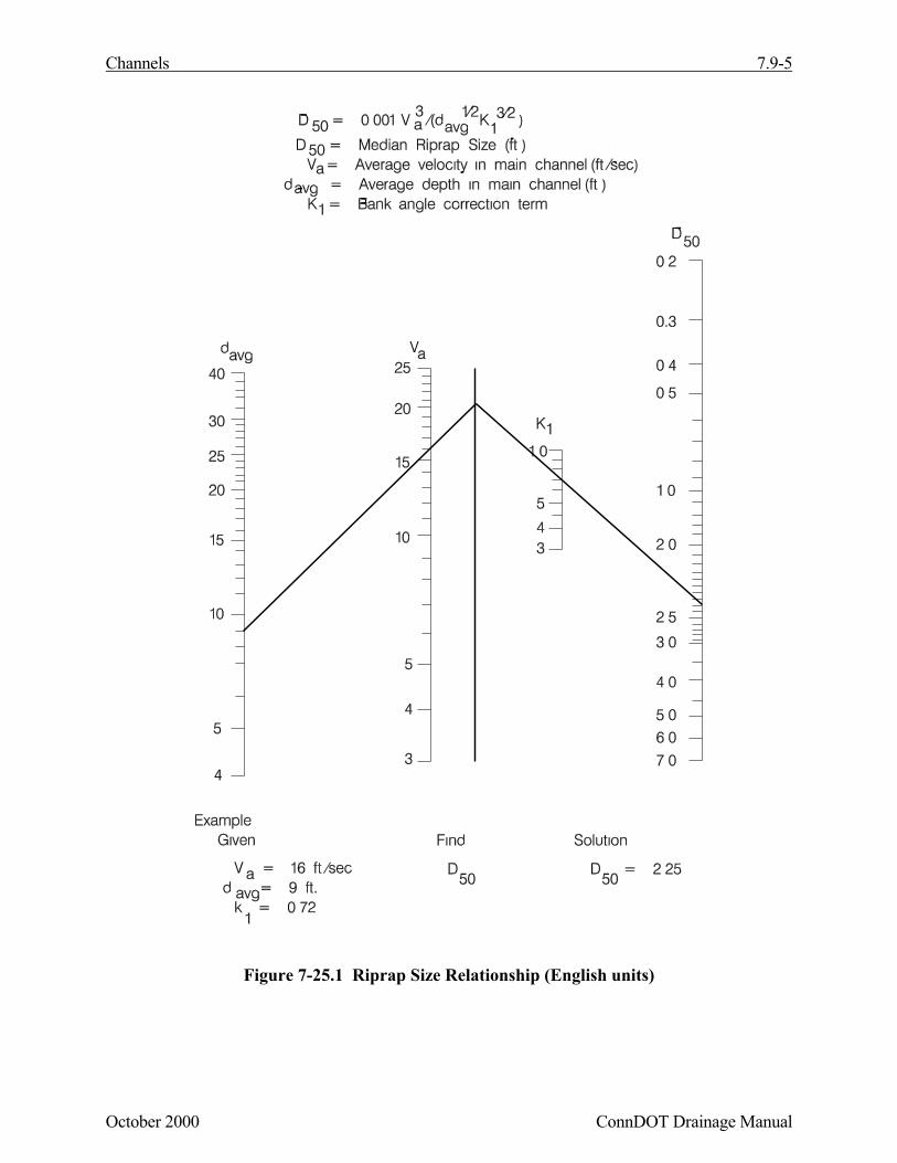
A riprap design relationship that is based on tractive force theory yet has velocity as its primarydesign parameter is presented in Equation 7.36. The design relationship in Equation 7.36 is basedon the assumption of uniform, gradually varying flow. Figure 7-25.1 presents a graphical solutionto Equation 7.36. Equation 7.37 can be solved using Figures 7-26 and 7-27.
D50 = 0.005 94 Va3 / (davg
0.5 K11.5) ( D50 = 0.001 Va
3 / (davg0.5 K1
1.5) ) (7.36)
Where: D50 = the median riprap particle size, m (ft)C = correction factor (described below)Va = the average velocity in the main channel, m/s (ft/s)davg = the average flow depth in the main flow channel, m (ft)
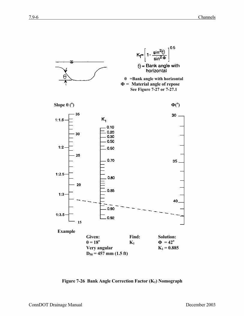
K1 is defined as:
K1 = [1-(sin2θ/sin2Φ)]0.5 (7.37)
Where: θ = the bank angle with the horizontalΦ = the riprap material's angle of repose
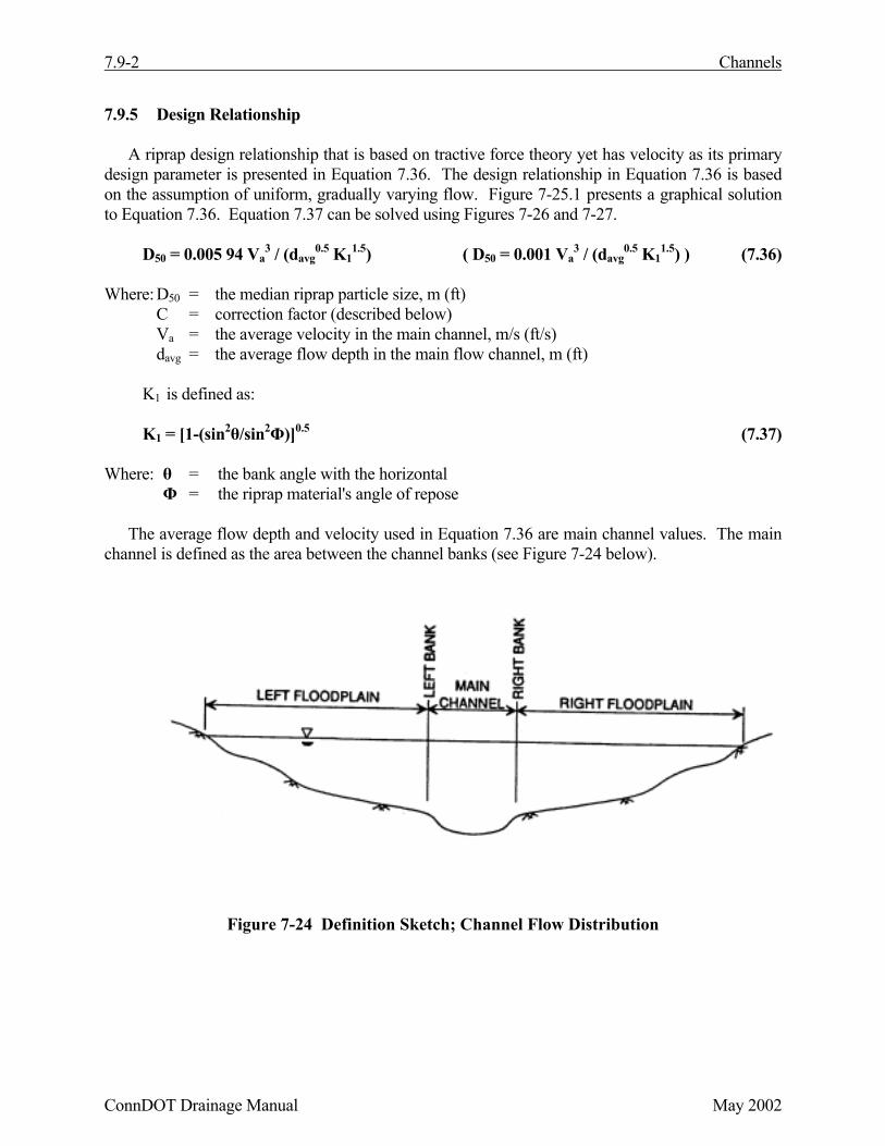
The average flow depth and velocity used in Equation 7.36 are main channel values. The mainchannel is defined as the area between the channel banks (see Figure 7-24 below).
Figure 7-24 Definition Sketch; Channel Flow Distribution
Channels 7.9-3
October 2000 ConnDOT Drainage Manual
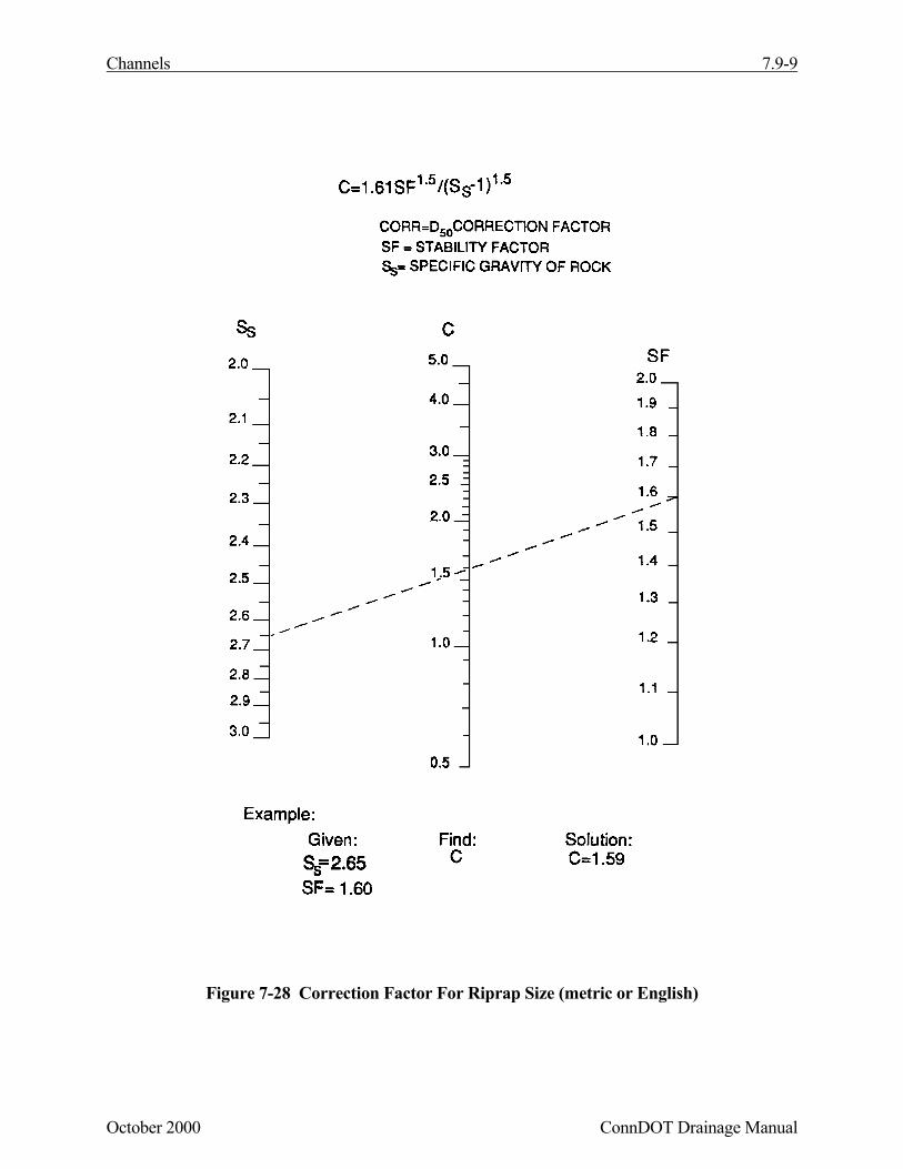
Equation 7.36 is based on a rock riprap specific gravity of 2.65, and a stability factor of 1.2.Equations 7.38 and 7.39 present correction factors for other specific gravities and stability factors.
Csg = 2.12/(Ss - 1)1.5 (7.38)
Where: Ss = the specific gravity of the rock riprap
Csf = (SF/1.2)1.5 (7.39)
Where: SF = the stability factor to be applied.The correction factors computed using Equations 7.38 and 7.39 are multiplied together to form a
single correction factor C. This correction factor, C, is then multiplied by the riprap size computedfrom Equation 7.35 to arrive at a stable riprap size. Figure 7-28 provides a solution to Equations7.39 and 7.38 using correction factor C.
The stability factor, SF, used in Equations 7.38 and 7.39 requires additional explanation. Thestability factor is defined as the ratio of the average tractive force exerted by the flow field and theriprap material's critical shear stress. As long as the stability factor is greater than 1, the criticalshear stress of the material is greater than the flow induced tractive stress, the riprap is considered tobe stable. As mentioned above, a stability factor of 1.2 was used in the development of Equation7.36.
The stability factor is used to reflect the level of uncertainty in the hydraulic conditions at aparticular site. Equation 7.36 is based on the assumption of uniform or gradually varying flow. Inmany instances, this assumption is violated or other uncertainties come to bear. For example, debrisand/or ice impacts, or the cumulative effect of high shear stresses and forces from wind and/or boatgenerated waves. The stability factor is used to increase the design rock size when these conditionsmust be considered. Table 7-7 presents guidelines for the selection of an appropriate value for thestability factor.
Figure 7-26 Bank Angle Correction Factor (K1) Nomograph
θ =Bank angle with horizontalΦ = Material angle of repose
See Figure 7-27 or 7-27.1
Slope θ (o) Φ(o)
ExampleGiven: Find: Solution:θ = 18o K1 Φ = 42o
Very angular K1 = 0.885D50 = 457 mm (1.5 ft)
15
Channels 7.9-7
October 2000 ConnDOT Drainage Manual
Figure 7-27 Angle Of Repose Of Riprap In Terms Of Mean Size And Shape Of Stone(metric units)
Ang
le o
f Rep
ose Φ
(deg
rees
)
7.9-8 Channels
ConnDOT Drainage Manual October 2000
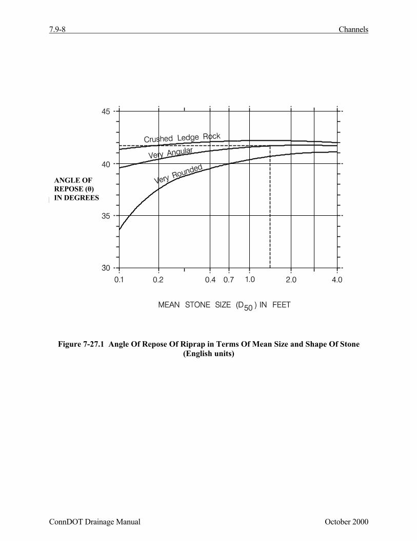
Figure 7-27.1 Angle Of Repose Of Riprap in Terms Of Mean Size and Shape Of Stone(English units)
ANGLE OFREPOSE (θ)IN DEGREES
Channels 7.9-9
October 2000 ConnDOT Drainage Manual
Figure 7-28 Correction Factor For Riprap Size (metric or English)
7.9-10 Channels
ConnDOT Drainage Manual October 2000
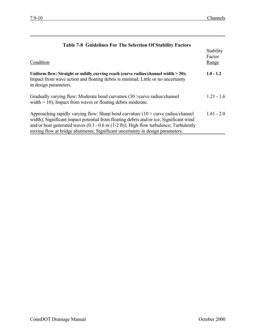
Table 7-8 Guidelines For The Selection Of Stability FactorsStabilityFactor
Condition Range
Uniform flow; Straight or mildly curving reach (curve radius/channel width > 30); 1.0 - 1.2Impact from wave action and floating debris is minimal; Little or no uncertaintyin design parameters.
Gradually varying flow; Moderate bend curvature (30 >curve radius/channel 1.21 - 1.6width > 10); Impact from waves or floating debris moderate.
Approaching rapidly varying flow; Sharp bend curvature (10 > curve radius/channel 1.61 - 2.0width); Significant impact potential from floating debris and/or ice; Significant windand/or boat generated waves (0.3 - 0.6 m (1-2 ft)); High flow turbulence; Turbulentlymixing flow at bridge abutments; Significant uncertainty in design parameters.
Channels 7.9-11
October 2000 ConnDOT Drainage Manual
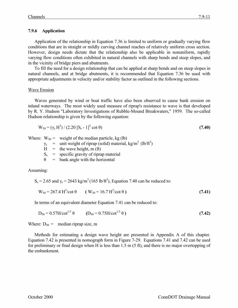
7.9.6 Application
Application of the relationship in Equation 7.36 is limited to uniform or gradually varying flowconditions that are in straight or mildly curving channel reaches of relatively uniform cross section.However, design needs dictate that the relationship also be applicable in nonuniform, rapidlyvarying flow conditions often exhibited in natural channels with sharp bends and steep slopes, andin the vicinity of bridge piers and abutments.
To fill the need for a design relationship that can be applied at sharp bends and on steep slopes innatural channels, and at bridge abutments, it is recommended that Equation 7.36 be used withappropriate adjustments in velocity and/or stability factor as outlined in the following sections.
Wave Erosion
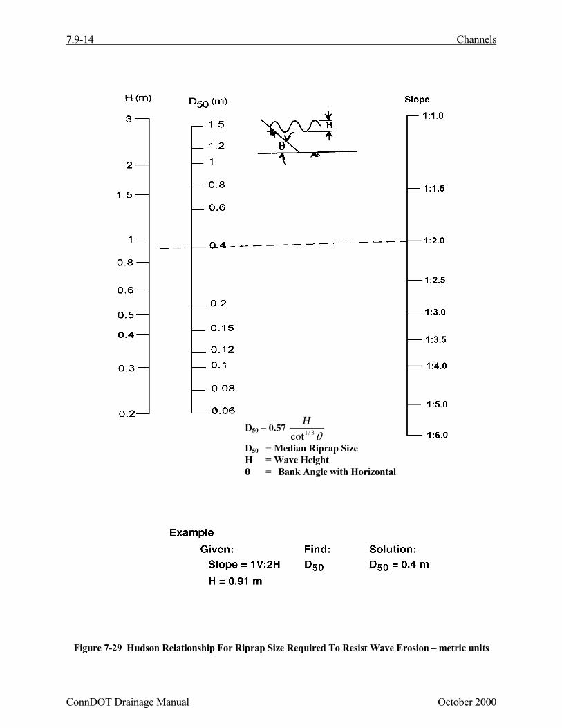
Waves generated by wind or boat traffic have also been observed to cause bank erosion oninland waterways. The most widely used measure of riprap's resistance to wave is that developedby R. Y. Hudson "Laboratory Investigations of Rubble-Mound Breakwaters," 1959. The so-calledHudson relationship is given by the following equation:
W50 = (γs H3) / (2.20 [Ss - 1]3 cot θ) (7.40)
Where: W50 = weight of the median particle, kg (lb)γs = unit weight of riprap (solid) material, kg/m3 (lb/ft3)H = the wave height, m (ft)Ss = specific gravity of riprap materialθ = bank angle with the horizontal
Assuming:
Ss = 2.65 and γs = 2643 kg/m3 (165 lb/ft3), Equation 7.40 can be reduced to:
Methods for estimating a design wave height are presented in Appendix A of this chapter.Equation 7.42 is presented in nomograph form in Figure 7-29. Equations 7.41 and 7.42 can be usedfor preliminary or final design when H is less than 1.5 m (5 ft), and there is no major overtopping ofthe embankment.
7.9-12 Channels
ConnDOT Drainage Manual October 2000
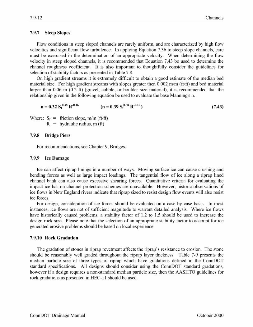
7.9.7 Steep Slopes
Flow conditions in steep sloped channels are rarely uniform, and are characterized by high flowvelocities and significant flow turbulence. In applying Equation 7.36 to steep slope channels, caremust be exercised in the determination of an appropriate velocity. When determining the flowvelocity in steep sloped channels, it is recommended that Equation 7.43 be used to determine thechannel roughness coefficient. It is also important to thoughtfully consider the guidelines forselection of stability factors as presented in Table 7.8.
On high gradient streams it is extremely difficult to obtain a good estimate of the median bedmaterial size. For high gradient streams with slopes greater then 0.002 m/m (ft/ft) and bed materiallarger than 0.06 m (0.2 ft) (gravel, cobble, or boulder size material), it is recommended that therelationship given in the following equation be used to evaluate the base Manning's n.
n = 0.32 Sf0.38 R-0.16 (n = 0.39 Sf
0.38 R-0.16 ) (7.43)
Where: Sf = friction slope, m/m (ft/ft)R = hydraulic radius, m (ft)
7.9.8 Bridge Piers
For recommendations, see Chapter 9, Bridges.
7.9.9 Ice Damage
Ice can affect riprap linings in a number of ways. Moving surface ice can cause crushing andbending forces as well as large impact loadings. The tangential flow of ice along a riprap linedchannel bank can also cause excessive shearing forces. Quantitative criteria for evaluating theimpact ice has on channel protection schemes are unavailable. However, historic observations ofice flows in New England rivers indicate that riprap sized to resist design flow events will also resistice forces.
For design, consideration of ice forces should be evaluated on a case by case basis. In mostinstances, ice flows are not of sufficient magnitude to warrant detailed analysis. Where ice flowshave historically caused problems, a stability factor of 1.2 to 1.5 should be used to increase thedesign rock size. Please note that the selection of an appropriate stability factor to account for icegenerated erosive problems should be based on local experience.
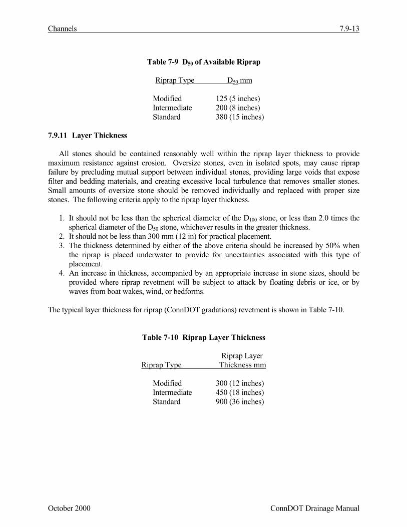
7.9.10 Rock Gradation
The gradation of stones in riprap revetment affects the riprap’s resistance to erosion. The stoneshould be reasonably well graded throughout the riprap layer thickness. Table 7-9 presents themedian particle size of three types of riprap which have gradations defined in the ConnDOTstandard specifications. All designs should consider using the ConnDOT standard gradations,however if a design requires a non-standard median particle size, then the AASHTO guidelines forrock gradations as presented in HEC-11 should be used.
All stones should be contained reasonably well within the riprap layer thickness to providemaximum resistance against erosion. Oversize stones, even in isolated spots, may cause riprapfailure by precluding mutual support between individual stones, providing large voids that exposefilter and bedding materials, and creating excessive local turbulence that removes smaller stones.Small amounts of oversize stone should be removed individually and replaced with proper sizestones. The following criteria apply to the riprap layer thickness.
1. It should not be less than the spherical diameter of the D100 stone, or less than 2.0 times thespherical diameter of the D50 stone, whichever results in the greater thickness.
2. It should not be less than 300 mm (12 in) for practical placement.3. The thickness determined by either of the above criteria should be increased by 50% when
the riprap is placed underwater to provide for uncertainties associated with this type ofplacement.
4. An increase in thickness, accompanied by an appropriate increase in stone sizes, should beprovided where riprap revetment will be subject to attack by floating debris or ice, or bywaves from boat wakes, wind, or bedforms.
The typical layer thickness for riprap (ConnDOT gradations) revetment is shown in Table 7-10.
Figure 7-29 Hudson Relationship For Riprap Size Required To Resist Wave Erosion – metric units
D50 = 0.57 θ3/1cot
H
D50 = Median Riprap SizeH = Wave Heightθ = Bank Angle with Horizontal
Channels 7.9-15
October 2000 ConnDOT Drainage Manual
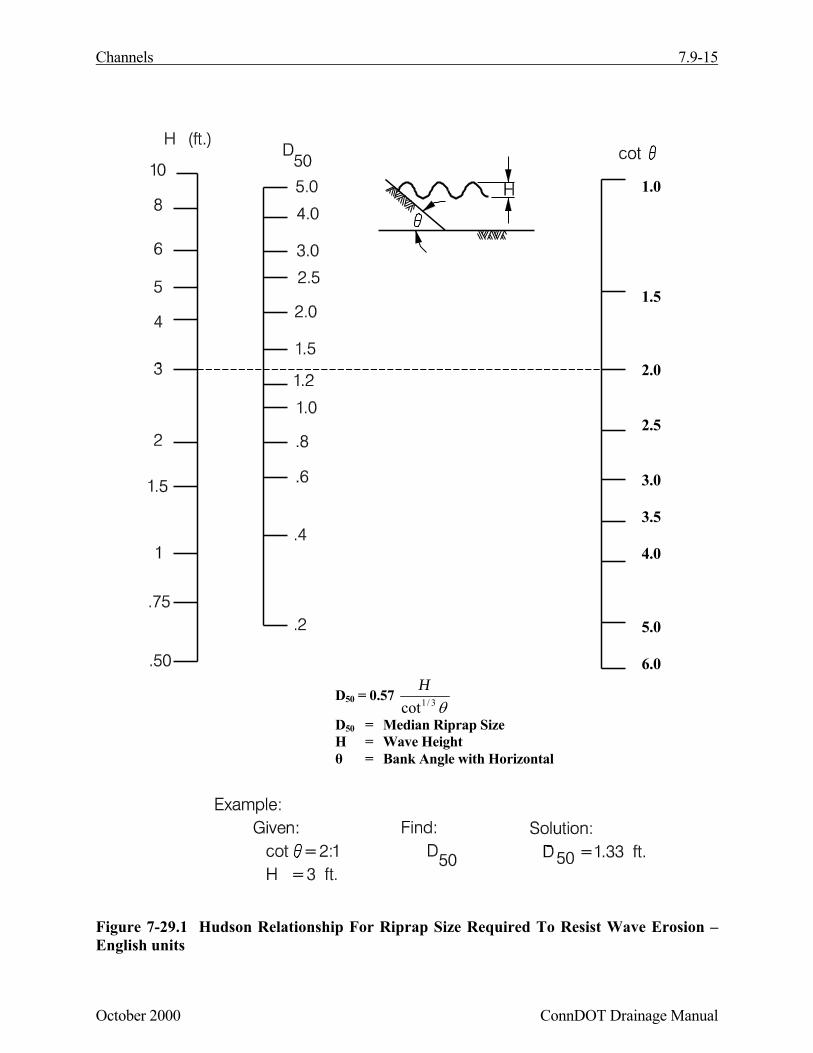
Figure 7-29.1 Hudson Relationship For Riprap Size Required To Resist Wave Erosion –English units
1.0
1.5
2.0
2.5
3.0
3.5
4.0
5.0
6.0
D50 = 0.57 θ3/1cot
H
D50 = Median Riprap SizeH = Wave Heightθ = Bank Angle with Horizontal
7.9-16 Channels
ConnDOT Drainage Manual October 2000
7.9.12 Filter Design
A filter is a transitional layer of gravel, small stone, or fabric placed between the underlying soiland the structure. The filter prevents the migration of the fine soil particles through voids in thestructure, distributes the weight of the armor units to provide more uniform settlement and permitsrelief of hydrostatic pressures within the soils. A filter should be used whenever the riprap is placedon noncohesive material subject to significant subsurface drainage (such as in areas where watersurface levels fluctuate frequently and in areas of high groundwater levels).
Granular Filters
Typical riprap installations use granular filters as a transitional layer between the riprap andunderlying soil. This layer shall consist of the item “Granular Fill” which is found in the standardspecifications. The required thickness of the granular fill layer based on the ConnDOT riprap typeis shown in Table 7-11.
In some cases further analysis of the granular filter layer may be warranted. Guidelines for granularfilter design are found in HEC-11.
Fabric Filters
Synthetic fabric filters have found considerable use as alternatives to granular filters. The followinglist of advantages relevant to using fabric filters have been identified:
• Installation is generally quick and labor-efficient• Fabric filters are more economical than granular filters• Fabric filters have consistent and more reliable material quality• Fabric filters have good inherent tensile strength• Local availability of suitable granular filter material is no longer a design consideration when
using fabric filters
Disadvantages include the following.
• Filter fabrics can be difficult to lay underwater• Installation of some fabrics must be undertaken with care to prevent undue ultraviolet light
exposure• Bacterial activity within the soil or upon the filter can control the hydraulic responses of a
fabric filter system
Channels 7.9-17
October 2000 ConnDOT Drainage Manual
• Experimental evidence indicates that when channel banks are subjected to wave action, non-cohesive bank material has a tendency to migrate downslope beneath fabric filters; thistendency was not observed with granular filters
• Fabric filters may induce translational or modified slump failures when used under rockriprap installed on steep slopes if not properly keyed into the top of slope
Filter Fabric Design
The filter cloth (geotextile) design should consider the following performance areas.
It is extremely desirable that individual site requirements be used to establish the necessaryrequirements. Generalized geotextile requirements should be used only on very small or non-critical/non-severe installations where a detailed analysis is not warranted. A discussion of theabove special considerations is found in Hydraulic Engineering circular No. 11.
The design process generally consists of the following design steps:
Step 1 - Evaluate the application site.Step 2 - Obtain and test soil samplesStep 3 - Evaluate possible armor choicesStep 4 - Calculate flow through geotextileStep 5 - Determine geotextile requirements:
a. Soil Retentionb. Permeabilityc. Cloggingd. Survivability
Filter Fabric Placement
To provide good performance, a properly selected cloth should be installed with due regard for thefollowing precautions:
• Heavy riprap may stretch the cloth as it settles, eventually causing bursting of the fabric intension. A 150mm (6 inch) gravel bedding layer should be placed beneath standard riprap.
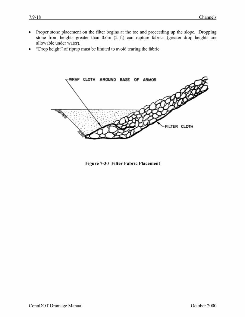
• The filter cloth should not extend into the channel beyond the riprap layer; rather, it should bewrapped around the toe material as illustrated in Figure 7-30.
• Adequate overlaps must be provided between individual fabric sheets.• The filter should be installed loosely to allow for any stretching under settlement.• Securing pins with washers are recommended at 0.6m to 1.5m (2 to 5 ft) intervals along the
midpoint of the overlaps.
7.9-18 Channels
ConnDOT Drainage Manual October 2000
• Proper stone placement on the filter begins at the toe and proceeding up the slope. Droppingstone from heights greater than 0.6m (2 ft) can rupture fabrics (greater drop heights areallowable under water).
• “Drop height” of riprap must be limited to avoid tearing the fabric
Figure 7-30 Filter Fabric Placement
Channels 7.9-19
October 2000 ConnDOT Drainage Manual
7.9.13 Edge Treatment
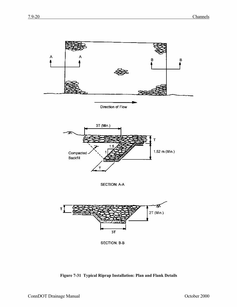
The edges of riprap revetments (flanks, toe and head) require special treatment to preventundermining. The flanks of the revetment should be designed as illustrated in Figure 7-31. Theupstream flank is illustrated in Section A-A and the downstream flank in Section B-B of this figure.A more constructible flank section uses riprap rather than compacted fill.
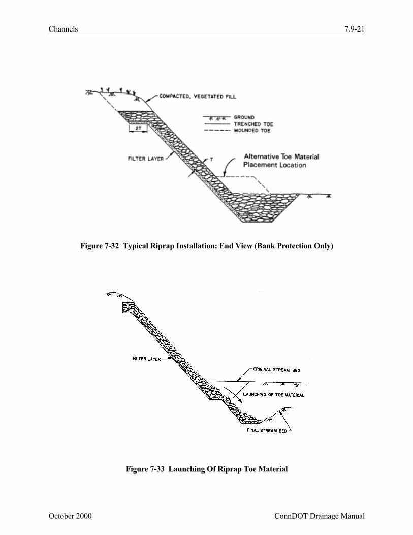
Undermining of the revetment toe is one of the primary mechanisms of riprap failure. The toe ofthe riprap should be designed as illustrated in Figure 7-32. The toe material should be placed in atoe trench along the entire length of the riprap blanket.
Where a toe trench cannot be dug, the riprap blanket should terminate in a thick, stone toe at thelevel of the streambed (see alternate design in Figure 7-32). Care must be taken during theplacement of the stone to ensure that the toe material does not mound and form a low dike; a lowdike along the toe could result in flow concentration along the revetment face which could stress therevetment to failure. In addition, care must be exercised to ensure that the channel's designcapability is not impaired by too much riprap in a toe mound.
The size of the toe trench or the alternate stone toe is controlled by the anticipated depth of scouralong the revetment. As scour occurs (and in most cases it will) the stone in the toe will launch intothe eroded area as illustrated in Figure 7-33. Observation of the performance of these types of rocktoe designs indicates that the riprap will launch to a final slope of approximately 1V:2H.
The volume of rock required for the toe must be equal to or exceed one and one-half times thevolume of rock required to extend the riprap blanket (at its design thickness and on a slope of1V:2H) to the anticipated depth of scour. Dimensions should be based on the required volumeusing the thickness and depth determined by the scour evaluation. The alternate location can beused when the amount of rock required would not constrain the channel. Establishing a designscour depth is covered in Section 7.8.8.
7.9-20 Channels
ConnDOT Drainage Manual October 2000
Figure 7-31 Typical Riprap Installation: Plan and Flank Details
Channels 7.9-21
October 2000 ConnDOT Drainage Manual
Figure 7-32 Typical Riprap Installation: End View (Bank Protection Only)
Figure 7-33 Launching Of Riprap Toe Material
7.9-22 Channels
ConnDOT Drainage Manual October 2000
7.9.14 Rock Riprap Design Procedure
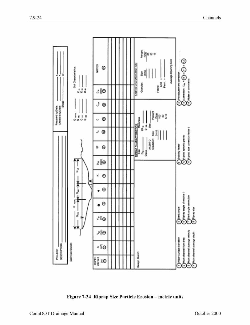
Rock riprap design procedure outlined in the following sections is comprised of three primarysections: preliminary data analysis, rock sizing and revetment detail design. The individual steps inthe procedure are numbered consecutively throughout each of the sections. Figure 7-34 provides auseful format for recording data at each step of the analysis.
Preliminary Data
Step 1 Compile all necessary field data including (channel cross section surveys, soils data, aerialphotographs, history of problems at site, etc.).
Step 2 Determine design discharge.
Step 3 Develop design cross section(s). Note: The rock sizing procedures described in thefollowing steps are designed to prevent riprap failure from particle erosion.
Step 4 Compute design water surface.
A. When evaluating the design water surface, Manning's n should be estimated. If ariprap lining is being designed for the entire channel perimeter, an estimate of the rocksize may be required to determine the roughness coefficient.
B. If the design section is a regular trapezoidal shape, and flow can be assumed to beuniform, design procedures in Section 7.7.3 can be used.
C. If the design section is irregular or flow is not uniform, backwater procedures must beused to determine the design water surface.
D. Any backwater analysis conducted must be based on conveyance weighing of flows inthe main channel, right bank and left bank.
Step 5 Determine design average velocity and depth.
A. Average velocity and depth should be determined for the design section in conjunctionwith the computations of step 4. In general, the average depth and velocity in the mainflow channel should be used.
B. If riprap is being designed to protect channel banks, abutments, or piers located in thefloodplain, average floodplain depths and velocities should be used.
Step 6 Compute the bank angle correction factor K1 (Equation 7.37, Figures 7-26 and 7-27).
B. Evaluate correction factor for rock riprap specific gravity and stability factor(C = CsgCsf).
C. If designing riprap for piers or abutments see Chapter 9, Bridges.
Step 8 If entire channel perimeter is being stabilized, and an assumed D50 was used indetermination of Manning's n for backwater computations, return to step 4 and repeatsteps 4 through 7 with the revised D50.
Step 9 If surface waves are to be evaluated:
A. Determine significant wave height.
B. Use Figure 7-29 to determine rock size required to resist wave action and Table 7-7for correction factor).
Step 10 Select final riprap.
Revetment Detail Design
Step 11 Determine longitudinal extent of protection required (section 7.8.8).
Step 12 Determine appropriate vertical extent of revetment (section 7.8.8).
Step 13 Design filter layer (section 7.9.12).
A. Determine appropriate filter material size, and gradation.
B. Determine layer thickness.
Step 14 Design edge details (flanks and toe) (section 7.9.13).
7.9-24 Channels
ConnDOT Drainage Manual October 2000
Figure 7-34 Riprap Size Particle Erosion – metric units
Channels 7.9-25
October 2000 ConnDOT Drainage Manual
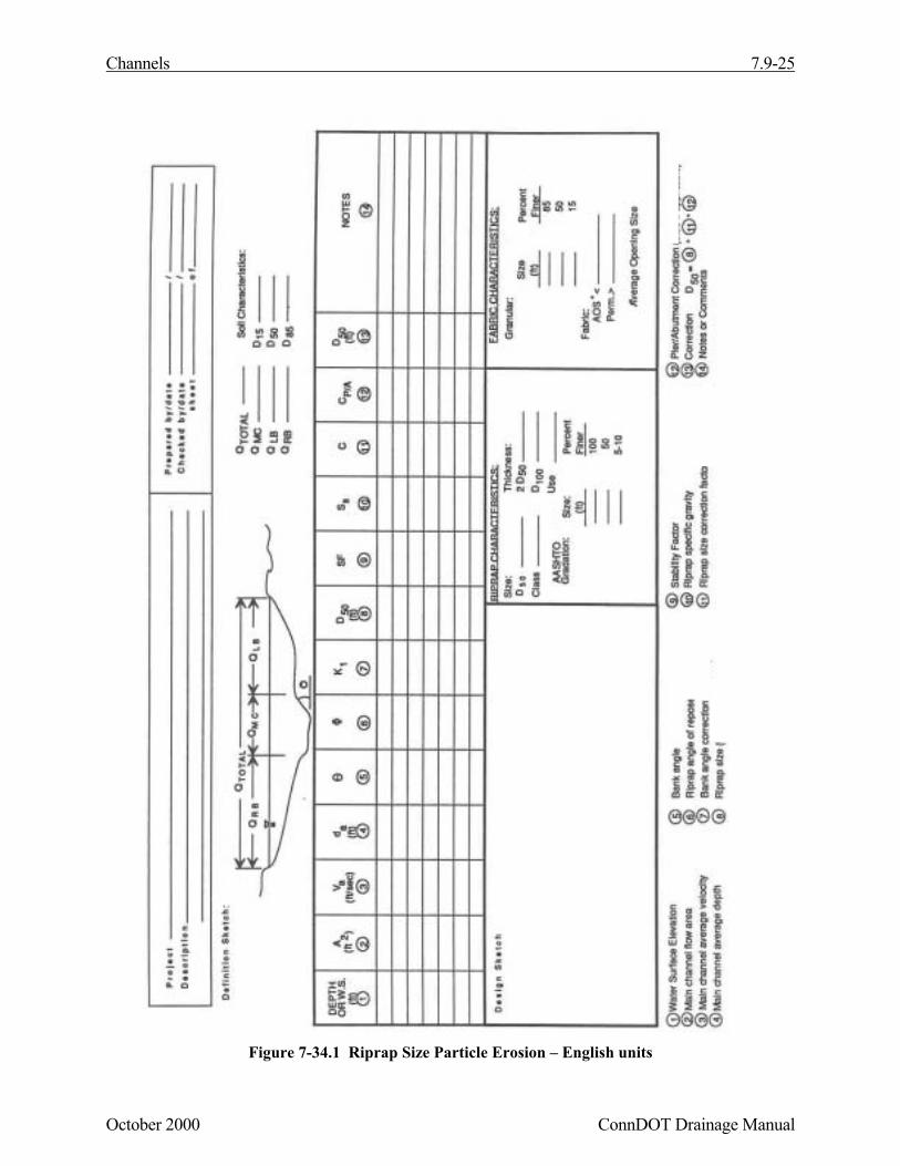
Figure 7-34.1 Riprap Size Particle Erosion – English units