Page 1
PINE RIVERS SHIRE COUNCIL
DESIGN MANUAL
CIVIL INFRASTRUCTURE DESIGN
DESIGN STANDARDS
Part 1 Design Standards for Roadworks
Part 2 Design Standards for Stormwater Drainage Works
Part 3 Design Standards for Water Supply Works
Part 4 Design Standards for Sewerage Works
Page 2
PINE RIVERS SHIRE COUNCIL
DESIGN STANDARDS
PART 3DESIGN STANDARDS FOR WATER SUPPLY WORKS
Section 1 Introduction
Section 2 Design Procedure
Page 3
Pine Rivers Shire Council
Design Manual
Design Standards - Part 3 – Water Supply - Section 2 – Design Procedure
January 2005
PINE RIVERS SHIRE COUNCIL
PART 3 - DESIGN STANDARDS FORWATER SUPPLY WORKS
SECTION 2 DESIGN PROCEDURE
2.1.0 PREAMBLE..................................................................................................................................... 1
2.2.0 HEADWORKS OR PRIORITY INFRASTRUCTURE PLANS ........................................................ 2
2.3.0 CONNECTION TO WATER ............................................................................................................ 3
2.3.1 Mandatory Connection to the Water Supply network......................................................................... 3
2.3.2 Special Exemption from Connection to Water Supply ....................................................................... 3
2.3.3 Connection to Water Supply not Required......................................................................................... 3
2.4.0 WATER............................................................................................................................................ 4
2.4.1 Future Demand for Water.................................................................................................................. 4
2.4.2 General.............................................................................................................................................. 4
2.4.3 Quantity of Water............................................................................................................................... 5
2.4.4 Quality of Water................................................................................................................................. 7
2.5.0 WATER SUPPLY NETWORK ........................................................................................................ 8
2.5.1 Distribution Systems.......................................................................................................................... 8
2.5.2 Work Through Private Property ....................................................................................................... 9
2.5.3 Trunk Mains Network....................................................................................................................... 9
2.5.4 Sizing of Trunk Mains ...................................................................................................................... 10
2.5.5 Reticulation Mains Network ............................................................................................................. 10
2.5.6 Sizing of Reticulation Mains ............................................................................................................ 10
2.5.7 Allotments with Restricted Access to Adequate Water Supply ........................................................ 14
2.5.8 Network Analysis Required.............................................................................................................. 15
2.5.9 Loop Mains...................................................................................................................................... 16
2.5.10 Property Service Connections ......................................................................................................... 17
2.5.11 Water Pressure ............................................................................................................................... 17
2.6.0 LOCATION OF WATER MAINS................................................................................................... 20
2.6.1 Locations for Mains ......................................................................................................................... 20
2.6.2 Alignment ........................................................................................................................................ 20
2.6.3 Cover Over Water Mains ................................................................................................................. 21
2.6.4 Clearance to Other Services ........................................................................................................... 22
Page 4
Pine Rivers Shire Council
Design Manual
Design Standards - Part 3 – Water Supply - Section 2 – Design Procedure
January 2005
2.7.0 DESIGN PRINCIPLES .................................................................................................................. 23
2.7.1 General............................................................................................................................................ 23
2.7.2 Material Selection ............................................................................................................................ 23
2.7.3 Materials’ Limitations ....................................................................................................................... 24
2.7.4 Trenches ......................................................................................................................................... 25
2.7.5 Above Ground Pipelines.................................................................................................................. 25
2.7.6 Protection of Water Main Pipes and Fittings.................................................................................... 26
2.7.7 Minimum Vertical Grades for Water Mains ...................................................................................... 26
2.7.8 Steep Pipelines................................................................................................................................ 27
2.7.9 Anchor Blocks ................................................................................................................................. 27
2.7.10 Joints ............................................................................................................................................... 28
2.7.11 Isolating Valves ............................................................................................................................... 30
2.7.12 Hydrants and Hydrant Points........................................................................................................... 32
2.7.13 Line Ends ........................................................................................................................................ 34
2.7.14 Air Release and Air Entry ................................................................................................................ 35
2.7.15 Scour Points .................................................................................................................................... 36
2.7.16 Connections to Existing Mains......................................................................................................... 37
2.7.17 Miscellaneous Fittings ..................................................................................................................... 37
2.7.18 Property Service Connections ......................................................................................................... 38
2.7.19 Service Conduits .............................................................................................................................39
2.7.20 Pipework in Pits and Chambers.......................................................................................................39
2.7.21 Water Draw-Off Points..................................................................................................................... 41
2.7.22 Telemetry ........................................................................................................................................ 42
2.7.23 Testing............................................................................................................................................. 42
2.7.24 Flushing and Sterilisation ................................................................................................................ 42
Page 5
1
Pine Rivers Shire Council
Design Manual
Design Standards - Part 3 – Water Supply - Section 2 – Design Procedure
January 2005
2.1.0 PREAMBLE
Water mains represent a significant investment in community infrastructure with an expected
long-term service life. Where a reticulated water supply is available, and required, the
community expects and demands access to this resource with a minimum of disruption and
inconvenience. Similarly, the consumer expects the water delivered to meet a consistent and
high quality in areas of colour and clarity, odour, taste and suitability for use.
In all elements associated with design and construction for a water supply network, regard for
these core expectations must be held uppermost.
Water is recognised as a valued commodity by the Pine Rivers Shire Council and the
community. The principles of water conservation must be considered and integrated into the
design and construction of the water reticulation system.
Page 6
2
Pine Rivers Shire Council
Design Manual
Design Standards - Part 3 – Water Supply - Section 2 – Design Procedure
January 2005
2.2.0 HEADWORKS OR PRIORITY INFRASTRUCTURE PLANS
The headworks or works toward priority infrastructure for which the Pine Rivers Shire Council
will require a contribution, are those identified as such in the headworks report or Priority
Infrastructure Plan (PIP). Works internal can be identified as those works generally within the
area of land which is the subject of the development application. Works external will be the
balance of works necessary in order that the sewerage service can be provided.
Matters relating to water supply headworks or priority infrastructure charges should be raised
by the developer at the time of lodging the development application with the Pine Rivers Shire
Council.
Charges will be levied in accordance with the relevant Headworks or Priority Infrastructure
Plan on all properties where the property or new allotments are required to be connected to
the reticulated water supply network, or where the developer has requested connection to the
reticulated water supply network. Also refer section 2.3.0 of the Design Standards for Water
Supply.
Page 7
3
Pine Rivers Shire Council
Design Manual
Design Standards - Part 3 – Water Supply - Section 2 – Design Procedure
January 2005
2.3.0 CONNECTION TO WATER
2.3.1 MANDATORY CONNECTION TO THE WATER SUPPLY NETWORK
All properties under development and new allotments in the following land use categories
shall to be connected to a reticulated water supply, with suitable flow and pressure to be
made available to the whole of the allotment area: -
Residential ‘A’
Residential ‘B’
Local Business
Central Business
Commercial
Neighbourhood Facilities
Home Industry
Service Industry
Future Urban
Special Residential
Park Residential
Future Rural Living
2.3.2 SPECIAL EXEMPTION FROM CONNECTION TO WATER SUPPLY
The creation of new allotments in the in the land use categories of: -
Special Residential
Park Residential
Future Rural Living
that do not meet the minimum requirements for water supply to permit direct connection to a
reticulated water supply network may be permitted, subject to consideration and approval by
the Pine Rivers Shire Council.
Properties of this nature are would be localised examples; and are the exception to the
normal requirements for connection to the reticulated supply network. Allotments are likely to
be an isolated few in a larger development.
Allotments in these land use areas may be connected to the reticulation network in
accordance with the requirements of section 2.5.7 of the Design Standards for Water Supply
Works.
2.3.3 CONNECTION TO WATER SUPPLY NOT REQUIRED
Allotments in the land use areas of: -
Rural Residential
Rural
are not required to be connected to the reticulated water supply network. A developer or
property owner may request approval from Pine Rivers Shire Council for the connection of
allotments in these areas to the reticulated network. Permission, if granted will be subject to
conditions similar to those applied for other land use areas.
Page 8
4
Pine Rivers Shire Council
Design Manual
Design Standards - Part 3 – Water Supply - Section 2 – Design Procedure
January 2005
2.4.0 WATER
2.4.1 FUTURE DEMAND FOR WATER
The expanding community will lead to an increased demand for potable water. However,
sources for and availability of raw water suitable for consumption are not likely to follow pace
with development.
This will lead to developers having to consider the demand their development will have for
water and implement innovative solutions to reduce the demand on the reticulated supply.
2.4.2 GENERAL
All designs shall comply with the requirements of these design standards, the requirements of
the Pine Rivers Shire Council Priority Infrastructure Plan (PIP) for Water Supply, the relevant
specifications and standard drawings herein, and relevant legislation.
The Pine Rivers Shire Council encourages the consulting engineer to incorporate such
specifications and drawings, as they may deem appropriate, into the project documentation.
By so doing, the consulting engineer accepts responsibility for their use as if they are the
authors of the specifications and drawings.
In designing water mains, the consulting engineer shall make allowance for any land, external
to the subject land, which ultimately will be serviced via the proposed works. The consulting
engineer shall obtain from the Pine Rivers Shire Council the details of all existing water supply
infrastructure into which the proposed works will connect.
All water supply works whether internal or external to the site, or both as the case may be,
relevant or reasonably required in respect of the proposed development, shall be provided at
the developer’s cost, unless the works are part of the Headworks or Priority Infrastructure
Plan (PIP) network.
In particular, the developer is required to meet the full cost of providing an appropriate
reticulated water supply system with capacity sufficient to pass through his or her land the
design flows and pressures required by all upstream properties, as determined by a Pine
Rivers Shire Council engineer, when such upstream properties are fully developed in
accordance with the Pine Rivers Shire Council Planning Scheme.
The water supply works shall be extended from an approved take-off point to the upstream
boundary of the development site unless otherwise approved by a Pine Rivers Shire Council
engineer.
The consultant shall verify that the existing downstream water supply system has sufficient
capacity to cater for the proposed development.
Any works necessary to upgrade the water supply network to cater for a particular
development shall be provided at the developer’s cost unless the upgrade works are part of
the Headworks or Priority Infrastructure Plan (PIP) network.
The costs, payments, contributions and credits associated construction of Headworks or PIP
items by a developer as part of any development works is covered by the relevant Pine Rivers
Shire Council policies.
Page 9
5
Pine Rivers Shire Council
Design Manual
Design Standards - Part 3 – Water Supply - Section 2 – Design Procedure
January 2005
2.4.3 QUANTITY OF WATER
Based on review of the State Government’s guidelines and Local Government practice in
South-east Queensland, the following parameters shall be used for design and assessment of
water supply systems. These factors are to be applied in accordance with procedures
detailed in the Queensland Department of Natural Resources and Mines Guidelines for
Planning and Design of Urban Water Supply, and the Pine Rivers Shire Council’s
requirements.
Table 2.4.0
CALCULATION OF WATER DEMAND
Item Description Adopted Design Parameter
Water Demand
1 Average Day demand (AD) 360 l/EP/d
Occupancy Ratio
2 Equivalent Person/
Equivalent Tenement
EP / ET
2.8 - for areas within the existing headworks boundary
2.6 - for areas outside the existing headworks boundary
Density of Development
3 Demand generated by
existing and future
development
Refer to Item 4
Demand Factors
4 Mean Day Maximum Month
(MDMM)
1.5 x AD
5 Maximum Day (MD) 2.25 x MDMM
6 Maximum Hour (MH) Residential Demand (l/Hr) = (4.5 24) x AD
Non-Residential Demand (l/Hr) = 3.4 24) x AD
Peak Demand Modeling Periods
7 Bulk Distribution Both the following Scenarios must be modeled; -
Scenario 1 - Reservoirs cannot empty under 3
consecutive maximum day demands
Scenario 2 - During MDMM demand, reservoir
shall have net positive inflow and
shall be capable of continuous
operation under this demand
8 Zonal Reticulation Flow and pressure levels of service must be satisfied under
3 consecutive days of maximum day demand
Page 10
6
Pine Rivers Shire Council
Design Manual
Design Standards - Part 3 – Water Supply - Section 2 – Design Procedure
January 2005
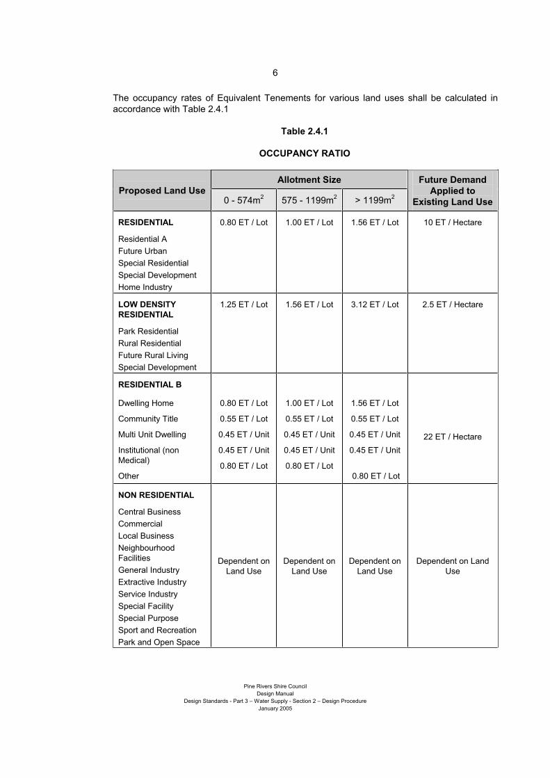
The occupancy rates of Equivalent Tenements for various land uses shall be calculated in
accordance with Table 2.4.1
Table 2.4.1
OCCUPANCY RATIO
Allotment Size Proposed Land Use
0 - 574m2
575 - 1199m2
> 1199m2
Future Demand
Applied to
Existing Land Use
RESIDENTIAL
Residential A
Future Urban
Special Residential
Special Development
Home Industry
0.80 ET / Lot 1.00 ET / Lot 1.56 ET / Lot 10 ET / Hectare
LOW DENSITY
RESIDENTIAL
Park Residential
Rural Residential
Future Rural Living
Special Development
1.25 ET / Lot 1.56 ET / Lot 3.12 ET / Lot 2.5 ET / Hectare
RESIDENTIAL B
Dwelling Home
Community Title
Multi Unit Dwelling
Institutional (non
Medical)
Other
0.80 ET / Lot
0.55 ET / Lot
0.45 ET / Unit
0.45 ET / Unit
0.80 ET / Lot
1.00 ET / Lot
0.55 ET / Lot
0.45 ET / Unit
0.45 ET / Unit
0.80 ET / Lot
1.56 ET / Lot
0.55 ET / Lot
0.45 ET / Unit
0.45 ET / Unit
0.80 ET / Lot
22 ET / Hectare
NON RESIDENTIAL
Central Business
Commercial
Local Business
Neighbourhood
Facilities
General Industry
Extractive Industry
Service Industry
Special Facility
Special Purpose
Sport and Recreation
Park and Open Space
Dependent on
Land Use
Dependent on
Land Use
Dependent on
Land Use
Dependent on Land
Use
Page 11
7
Pine Rivers Shire Council
Design Manual
Design Standards - Part 3 – Water Supply - Section 2 – Design Procedure
January 2005
2.4.4 QUALITY OF WATER
The quality of water delivered to the consumer must be in accordance with the Australian
Drinking Water Guidelines 1996.
Whilst the quality of reticulated water is initially determined by the quality of raw water, and the
filtration and treatment control processes, the distribution system also shares a role in
maintaining the quality of supply.
The layout of the distribution network, design of major and minor individual mains and other
elements within the network, selection of materials and construction standards each have a
contribution to make in maintaining reticulated water quality within the established standards.
Circumstances may arise where a diminished quality of water below the required standards
could occur due to localised circumstances. Designers must be sensitive to maintaining
water quality standards by considering low-flow or low demand characteristics in major mains
and installations. With the reticulation network, configuring the layout to reduce dead-end
mains, locating property service connections well before the end of mains and including loop
mains will all assist in maintaining water quality for the end customer.
Many of these can be minimised by including the criteria established in these standards into
design of the main. The following cases should be avoided:-
consider decay of disinfecting agent by long sections of dead-end mains without constant
and reliable demand
detention times in large concrete-lined mains where the pH may be effected
sections of low velocities in mains – segments of varying diameter may be required
Recognition of these circumstances, the inclusion of safeguards and often innovative
solutions from the project designer are necessary.
Page 12
8
Pine Rivers Shire Council
Design Manual
Design Standards - Part 3 – Water Supply - Section 2 – Design Procedure
January 2005
2.5.0 WATER SUPPLY NETWORK
2.5.1 DISTRIBUTION SYSTEMS
The distribution system includes all water supply infrastructure from the source to individual
property service connections for the total area serviced by a reticulated water supply. The
distribution system includes pumping stations, reservoirs, trunk mains and reticulation mains.
These components of the distribution system are discussed further below.
Pumping Stations are located within the water supply system to transport and lift water to
the required levels within service reservoirs to ensure supply to consumers over the
distribution area. They may also be used to boost flows or pressures within pipelines to
satisfy the system demand.
Service Reservoirs are water storage facilities located strategically throughout the
serviced area. They provide storage capacity to balance out fluctuations in demand and
operating pressures for a serviced area and reserve storage for emergencies.
Trunk Mains are larger diameter pipelines supplying water from one major component in
the network to another e.g. service reservoirs. Trunk mains may also be a system of larger
pipelines supplying water from a major component to or about an area of smaller pipelines
within the reticulation system.
Trunk mains are considered to be pipelines of 300 mm diameter or greater, except in
Dayboro and Samford areas where trunk mains are considered to be 225 mm diameter or
greater.
The primary purpose of trunk mains is for transport of water and thus, they are generally
not used for direct connection of property services. Property service connections may be
made under special circumstances.
Reticulation Mains are relatively small diameter water mains that distribute flows from
trunk mains or service reservoirs to the consumer. Reticulation mains are generally up to
200 mm diameter in areas except for Samford and Dayboro where reticulation mains are
generally limited to less than 200 mm diameter.
Property service connections are usually made with reticulation mains for supply to
individual consumers.
Where water mains of trunk mains size have property service connections supplying each
property within an urban or park residential areas, then these mains are considered as
reticulation mains as they serve a dual function.
Property Service Connection is the section of pipework and fittings (including water
meter) maintained by the Pine Rivers Shire Council that connects individual properties to
the water main and provides the point to which the land owner will connect their property
service.
Page 13
9
Pine Rivers Shire Council
Design Manual
Design Standards - Part 3 – Water Supply - Section 2 – Design Procedure
January 2005
Property Service is the private supply system from the connection point off the reticulation
(or trunk) main to private property, dwelling etc. The property service may supply a single
allotment or building, or multiple allotments or buildings etc. in the case of a community title
development.
Property service connections shall only be made to trunk mains where special
circumstances exist and with written approval from the General Manager, Pine Water.
2.5.2 WORK THROUGH PRIVATE PROPERTY
In the event that works are to be constructed through property not under the control of the
developer, arrangements shall be made with the Pine Rivers Shire Council to obtain the
names of affected property owners. Works shall not be undertaken in property not under
control of the developer without prior written consent of the registered property owner. A copy
of the owner’s written consent shall be provided to a Pine Rivers Shire Council engineer.
Water mains constructed on private property are to be avoided wherever possible. Water
mains on private property require approval from the General Manager, Pine Water. Where
water mains are constructed on private property, easements are to be taken over the subject
land along the route of the water main, including all associated works and thrust blocks. The
minimum width is to be 4.0 m. Easements shall be registered in the name of the owner or
party responsible for the future condition and maintenance of the water main.
A Pine Rivers Shire Council engineer shall be provided with a letter signed from the registered
owner stating that all reinstatement work has been satisfactorily carried out prior to the Pine
Rivers Shire Council accepting work constructed in private property “on maintenance”.
2.5.3 TRUNK MAINS NETWORK
The network of trunk mains represents the major arteries transporting water around the Pine
Rivers Shire.
They will connect a water treatment plant with storage reservoirs, and storage reservoirs with
the reticulation network, for distribution of water to the consumer.
Trunk mains are an interconnected network of pipelines that are strategically sized and
located to link between key nodes in the water supply network. The network represents a
series of loops that ensures a supply of water is available to all areas within the water supply
area at all times.
In some circumstances, due to the order of development or in outlying areas, a trunk main
may be installed that represents the sole means of supply into a consumer area. In these
circumstances, the Pine Rivers Shire Council will require that the area be connected to the
major network to develop a looped supply as soon as practicable to ensure continuity of
supply to consumers and a satisfactory standard of water is delivered.
The construction of an interconnection main may be required by a Pine Rivers Shire Council
engineer where it is deemed necessary to ensure a desirable level of service is available to
the consumer.
In these circumstances, a smaller diameter pipeline than would be normally required may be
approved by a Pine Rivers Shire Council engineer.
Page 14
10
Pine Rivers Shire Council
Design Manual
Design Standards - Part 3 – Water Supply - Section 2 – Design Procedure
January 2005
2.5.4 SIZING OF TRUNK MAINS
Trunk main sizes will be determined by a dynamic network analysis.
The results of the network analysis are detailed in a Network Master Plan. Trunk main sizes
shall be determined by referring to the most recent copies of this master plan.
2.5.5 RETICULATION MAINS NETWORK
The reticulation mains distribute water from trunk mains to the consumers.
The network of reticulation mains must be laid out as a ring-feed or looped system. A “tree”
configuration of branch mains that do not interconnect will not be accepted.
The reticulation network must provide for the delivery of water to consumers from a variety of
directions to ensure supply is maintained to the maximum number of consumers during
downtime of any section of main for repair or maintenance.
The layout and configuration of the reticulation network must ensure that not more than 40
properties will be without water at any time because of downtime on a section of reticulation
main.
It is acknowledged that the order of some developments may require a long length of
reticulation main to be constructed to service an area, and that downtime on such a main may
result in a significant number of properties experiencing loss of water supply.
Layouts promoting numerous branch mains that result in “ends” that do provide a ring feed
interconnection to another main will not be accepted. Wherever opportunities exist,
reticulation mains are to be interconnected with mains in adjacent streets to create a loop
configuration.
Looped interconnection may be omitted on ends of streets where future extensions of the
street are proposed.
Where cul-de-sac streets have a pathway link through to another street, the reticulation main
shall be connected to the main in the adjacent street through the pathway link via a loop main.
Parks and pathway links between streets can also be used to provide a looped configuration
of mains.
2.5.6 SIZING OF RETICULATION MAINS
Reticulation or distribution mains shall be designed to carry the flows required to comply with
Table 2.4.0 (refer to Section 2.4.3 of the Design Standards for Water Supply Works).
Reticulation mains are to be sized and interconnected to provide sufficient redundant capacity
to allow for interruption of flow from one direction. In general, the minimum acceptable
diameter of pipes serving more than 24 residential properties shall be 150mm.
For Commercial / Industrial areas, the minimum water main diameter is 150mm.
The absolute minimum pressure will only be permitted in isolated, small, highly elevated
areas.
Page 15
11
Pine Rivers Shire Council
Design Manual
Design Standards - Part 3 – Water Supply - Section 2 – Design Procedure
January 2005
Reference should also be made to the Network Master Plan for any special requirements
within the proposed development.
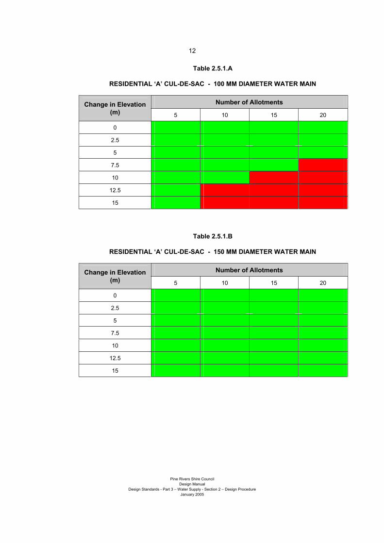
Developments less than 2.0 hectares
- Residential A and Park Residential Cul-de-Sacs
The following information can be used for determining the number of allotments that can be
serviced from a 100 and 150 mm diameter water main in a small Residential ‘A’ or Park
Residential developments of a single cul-de-sac. Figure 2.5.0 shows the configuration of cul-
de-sacs this design criterion may be used for.
Figure 1
Figure 2.5.0
The values shaded green (light coloured) in the Tables 2.5.1 and 2.5.2 below can be serviced,
whilst those shaded red (dark coloured) cannot be provided for, due to less than permissible
pressure or flow. Not more than 20 allotments are permitted in any cul-de-sac.
The change in elevation referred to in the tables indicates the difference in elevation between
the supply main serving the cul-de-sac branch and the highest point along the cul-de-sac.
This high point can be located at any point - as a hump - along the cul-de-sac and is not
necessarily at the end of the street.
The water supply main servicing the cul-de-sac must have two connections to the network in
its ultimate state of development. The cul-de-sac may be serviced from a section of dead end
main, provided the network analysis proves that sufficient pressure and flow is available at the
critical supply node feeding the end of main and cul-de-sac.
In some instances of development layout and sequencing where the second interconnection
of a water supply main to the network has not been completed, it may be appropriate to
question the validity of the following tables. In these circumstances, a network analysis that
includes the water supply main and cul-de-sac may be required.
Water Supply Main
Page 16
12
Pine Rivers Shire Council
Design Manual
Design Standards - Part 3 – Water Supply - Section 2 – Design Procedure
January 2005
Table 2.5.1.A
RESIDENTIAL ‘A’ CUL-DE-SAC - 100 MM DIAMETER WATER MAIN
Number of Allotments Change in Elevation
(m) 5 10 15 20
0
2.5
5
7.5
10
12.5
15
Table 2.5.1.B
RESIDENTIAL ‘A’ CUL-DE-SAC - 150 MM DIAMETER WATER MAIN
Number of Allotments Change in Elevation
(m) 5 10 15 20
0
2.5
5
7.5
10
12.5
15
Page 17
13
Pine Rivers Shire Council
Design Manual
Design Standards - Part 3 – Water Supply - Section 2 – Design Procedure
January 2005
Table 2.5.2.A
SPECIAL AND PARK RESIDENTIAL CUL-DE-SAC
100 MM DIAMETER WATER MAIN
Number of Allotments Change in Elevation
(m) 5 10 15 20
-15
-12.5
-10
-7.5
-5
-2.5
0
2.5
5
7.5
10
12.5
Table 2.5.2.B
SPECIAL AND PARK RESIDENTIAL CUL-DE-SAC
150 MM DIAMETER WATER MAIN
Number of Allotments Change in Elevation
(m) 5 10 15 20
0
2.5
5
7.5
10
12.5
15
Page 18
14
Pine Rivers Shire Council
Design Manual
Design Standards - Part 3 – Water Supply - Section 2 – Design Procedure
January 2005
A network analysis will be required where a localised boosted supply is to be provided to
allotments as part of the development.
Where the development layout requires a reticulation main to continue past a loop main
connection to service properties, the reticulation main diameter beyond this point may be
reduced to assist in maintaining water quality provided all flow and pressure requirements are
able to be met. Mains providing service connections to properties shall not be less than 100
mm diameter.
Developments Over 2 Hectares, and Other Zones
A reticulation network analysis will be required for all developments over 2 ha in area, and for
developments with uses other than those provided in the above tables.
2.5.7 ALLOTMENTS WITH RESTRICTED ACCESS TO ADEQUATE WATER SUPPLY
In some localised areas of the Pine Rivers Shire, house sites may be found which are unable
to be supplied with reticulated water due to their elevation and inability to comply with the
absolute minimum design criteria. Typically, these locations should only be expected in land
use areas designated as Special Residential, Park Residential and Future Rural Living.
In the land use areas mentioned above allotments may be permitted which do not meet the
minimum criteria in the Design Standards for Water Supply for connection to the reticulated
water network.
Allotments in these land use areas may fall into the criteria listed in Table 2.5.3, with the
corresponding options for connection to the reticulated water supply network.
Page 19
15
Pine Rivers Shire Council
Design Manual
Design Standards - Part 3 – Water Supply - Section 2 – Design Procedure
January 2005
Table 2.5.3
Case Availability of Adequate
Water Supply
Connection Options
1 Allotments able to be serviced
by the reticulated water network
a) Construction of water mains to provide for connection
of allotments to the water supply network is
mandatory
2 Allotments where adequate
supply of reticulated water is
only available to a maximum
specific level (RL) across an
allotment
b) The developer may elect not to construct a water
main specifically for these allotments.
c) The Developer may elect to provide for connection of
the allotment to the water supply network by
constructing a water main past the allotment frontage
d) Water is available due to service the need to service
other allotments in accordance with Case 1
3 Allotments where adequate
supply is only available to the
frontage of an allotment
b) The developer may elect not to construct a water
main specifically for these allotments.
c) The Developer may elect to provide for connection of
the allotment to the water supply network by
constructing a water main past the allotment frontage
d) Water is available due to service the need to service
other allotments in accordance with Case 1
4 Allotments where adequate
supply is not available to the
frontage of an allotment
e) The option for provision of a reticulated water supply
to these properties is not available to the developer
Adequate water supply is defined as “Provision of water to the whole of an allotment in accordance with
the minimum criteria for the Design Standards for Water Supply”.
Where the ability to connect an allotment to the reticulated water supply is provided in
accordance with Case 2(c and d) and 3(c and d) of Table 2.5.3, the developer will accept
Council placing a note on the property detailing conditions under which a reticulated water
supply is provided to the allotment. This note will be made available to prospective
purchasers of the allotment.
The provision of the water connection remains the responsibility of the property owner. The
connection of allotments meeting Case 2 (c and d) and 3 (c and d) of Table 2.5.3 shall be
connected to the network in accordance with the relevant Council Policy.
2.5.8 NETWORK ANALYSIS REQUIRED
A developer will be required to conduct a network analysis where the proposed development
is out of sequence with the priority infrastructure plan or where interim or unexpected staging
of mains is proposed. An analysis for sizing of reticulation mains will be required as
addressed in Section 2.5.6 of the Design Standards for Water Supply Works.
A network analysis will also be required if the development area is the subject of a major
development that is of a higher density of use than has been considered in formulating the
Pine Rivers Shire Council reports. Smaller developments that are of higher density than
Page 20
16
Pine Rivers Shire Council
Design Manual
Design Standards - Part 3 – Water Supply - Section 2 – Design Procedure
January 2005
envisaged by the Pine Rivers Shire Council in its planning scheme may be required to
undertake analysis to determine the adequacy of the water supply network on a surrounding
local area scale.
Where a network analysis is required, the analysis is to give consideration to and is to include
details of: -
how the proposed development will influence the current augmentation plan
the effect on the existing water supply network (trunk and reticulation)
changes required to the existing water supply network should the development proceed,
including timing of works
changes required to the proposed network augmentation in the priority infrastructure plan
should the development proceed, including timing of works
where a localised boosted supply is involved, shall ensure the design and installation of
boosted supply does not unduly affect the remainder of the water supply network
2.5.9 LOOP MAINS
Loop mains consist of a pipeline constructed between one reticulation main and another to
create a looped system for improved service and flow in the network. It is desirable that the
subdivision road layout is designed to create looped roads to assist in satisfying this criterion.
However, loop mains may use pathway connections, parkland and areas of crown land to
connect between mains.
As a loop mains purpose is to supplement the “major” reticulation mains to a street or area,
they may be of a reduced diameter than would ordinarily be required to service an area.
By nature, loop mains serve as a reticulation main. However, property service connections
are not permitted from the loop main.
Construction standards and all other requirements for reticulation mains remain applicable to
loop mains. An isolation valve is required near each end of the loop main. Hydrants would
not necessarily be required on a loop main for fire fighting purposes as the major reticulation
system provides this function. Hydrants will be required in low points or high points for air
entry/release and scour purposes.
Where loop mains are constructed through parks and reserves, loop mains may be used to
supply water to the park. Loop mains may also be used to supply community buildings in
parks if the level of supply is adequate. If a community building is some distance from the
regular reticulation main, a hydrant may be fitted to the loop main near to the building.
Table 2.5.4
SIZING OF LOOP MAINS
Reticulation Main Diameter Minimum Diameter for Loop Main
100 mm 63 mm PN8 PE80B (MDPE)
150 mm 63 mm PN8 PE80B (MDPE)
200 mm 100 mm (PVC)
225 mm 100 mm (PVC)
250 mm 100 mm (PVC)
Page 21
17
Pine Rivers Shire Council
Design Manual
Design Standards - Part 3 – Water Supply - Section 2 – Design Procedure
January 2005
2.5.10 PROPERTY SERVICE CONNECTIONS
The property service connection describes the length of pipework and fittings between the
reticulation main and the point at which the property owner connects their private plumbing
system to the water supply network. The property service connection is owned and
maintained by the Pine Rivers Shire Council and includes the stopcock and water meter.
The private plumbing system is connected to the property service connection by the private
land owner.
The Pine Rivers Shire Council has produced a number of standard drawings showing the
configuration of property service connections.
2.5.11 WATER PRESSURE
All mains shall be designed to carry the demand covered in Section 2.4.3 of the Design
Standards for Water Supply Works, whilst maintaining a minimum allowable pressure.
Page 22
18
Pine Rivers Shire Council
Design Manual
Design Standards - Part 3 – Water Supply - Section 2 – Design Procedure
January 2005
Table 2.5.5
REQUIREMENTS FOR WATER PRESSURE
Item Description Adopted Design Parameter
System Pressure
1 Minimum Operating
Pressure
22 m above the highest elevation on any allotment in the
pressure zone with the water level in the reservoir not less
than 1.5 m below top water level
2 Absolute Minimum
Operating Pressure
In isolated high level areas the minimum operating
pressure may be reduced to 16 m above the highest
elevation on any allotment with the water level in the
reservoir not more than 1.0 m above reservoir floor level
3 Maximum Operating
Pressure
80 m above the lowest elevation of any allotment in the
pressure zone
Fire Fighting Requirements
4 System Pressure 12 m minimum at any location in the reticulation mains with
model conditions as detailed in this table below.
5 Fire Flow Residential - 15 l/sec (simultaneous with
background demand)
Commercial/Industrial -
30 l/sec (simultaneous with
background demand)
Special Risk/Hazardous Land Use -
To be assessed
6 Background Demand MH demand - Refer to Table 2.4.0, Section 2.4.3 of these
Design Standards
7 Reservoir Level (AHD) Set at Reservoir Mid-Water Level (MWL) where:-
MWL = (Top Water Level – Floor Level) 2
The absolute minimum pressure will only be permitted in special circumstances.
Reticulation Mains Network
The maximum allowable working pressure in the reticulation network providing direct supply
to consumers is 80 m static head or 800 kPa at the property frontage to prevent damage to
private plumbing, fixtures and fittings.
Where consumers are to be serviced from a main exceeding the permitted reticulation
pressure, a pressure reducing valve (PRV) is to be installed to ensure pressures downstream
of the PRV are maintained at a suitable maximum and minimum pressure range. Care must
be taken to ensure pressures are controlled in the reticulation loop and that trunk main
pressure is maintained at the higher range where necessary. This may require PRVs at
various locations where interconnection with a higher pressure trunk main occurs.
Page 23
19
Pine Rivers Shire Council
Design Manual
Design Standards - Part 3 – Water Supply - Section 2 – Design Procedure
January 2005
Details for pressure reducing valve installations can be found in the Pine Rivers Shire Council
standard drawings.
Trunk Mains Network
The maximum operating pressure in the trunk mains network is controlled only by the
availability of pipes, fittings and components of a suitable pressure rating to withstand
operating pressures, including those associated with water hammer and pumping surges
within these mains for the design life of the water main.
Pressure Zones
To provide an adequate standard of service across varying elevations in the Pine Rivers
Shire, the water supply network has been “sectioned” into pressure zones that have different
operating ranges for the hydraulic grade line of the network.
The pressure zones are detailed in the Water Supply Network Master Plan.
Care shall be taken by the designer to ensure they have a satisfactory understanding of the
water supply networks in the area they will be working to ensure cross connection between
these separate systems does not occur.
Page 24
20
Pine Rivers Shire Council
Design Manual
Design Standards - Part 3 – Water Supply - Section 2 – Design Procedure
January 2005
2.6.0 LOCATION OF WATER MAINS
2.6.1 LOCATIONS FOR MAINS
Water mains shall generally be located along road reserves or across areas of public space.
Water mains will only be permitted across private land under exceptional circumstances, and
only with written authority from the General Manager Pine Water, and the owner of the
property across which the water main is to be located.
Where a water main has, or is required to be constructed in or over private property, the Pine
Rivers Shire Council requires an easement to be provided over the subject land. The
easement shall cover the entire route of the main, encompass all associated fittings, pits or
chambers and thrust blocks etc. The width of the easement shall be suitable for access by
vehicles and plant as may be considered appropriate for maintenance and works on the water
main.
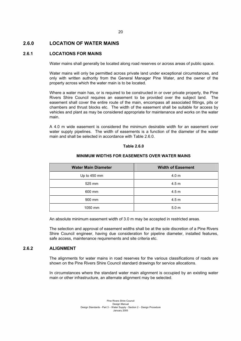
A 4.0 m wide easement is considered the minimum desirable width for an easement over
water supply pipelines. The width of easements is a function of the diameter of the water
main and shall be selected in accordance with Table 2.6.0.
Table 2.6.0
MINIMUM WIDTHS FOR EASEMENTS OVER WATER MAINS
Water Main Diameter Width of Easement
Up to 450 mm 4.0 m
525 mm 4.5 m
600 mm 4.5 m
900 mm 4.5 m
1050 mm 5.0 m
An absolute minimum easement width of 3.0 m may be accepted in restricted areas.
The selection and approval of easement widths shall be at the sole discretion of a Pine Rivers
Shire Council engineer, having due consideration for pipeline diameter, installed features,
safe access, maintenance requirements and site criteria etc.
2.6.2 ALIGNMENT
The alignments for water mains in road reserves for the various classifications of roads are
shown on the Pine Rivers Shire Council standard drawings for service allocations.
In circumstances where the standard water main alignment is occupied by an existing water
main or other infrastructure, an alternate alignment may be selected.
Page 25
21
Pine Rivers Shire Council
Design Manual
Design Standards - Part 3 – Water Supply - Section 2 – Design Procedure
January 2005
When investigating an alternate water main alignment, the designer shall consider all future
design criteria for the roadway and undertake a thorough investigation of the future use of the
proposed route. These shall include, among other things:-
road classification and future construction standard
future land use
horizontal alignment and road widening
alignment and allocations for other services infrastructure
future service infrastructure allocations and requirements
environmental values
Details of the alternate alignment chosen, together with supporting information shall be
provided to a Pine Rivers Shire Council engineer for approval.
2.6.3 COVER OVER WATER MAINS
The minimum cover over water mains in various locations is shown on the Pine Rivers Shire
Council standard drawings and this cover shall be adhered to over the full length of the main.
Where water mains are to be constructed along or across routes controlled by other
authorities, these authorities may have specifications requiring more cover than those
required by the Pine Rivers Shire Council.
In any case, the Pine Rivers Shire Council cover requirements remain the minimum. The
minimum cover values are based on various criteria including:-
maintaining a satisfactory cover to reticulation mains whilst permitting minor earthworks on
the verge for driveways etc
sufficient cover to maintain the structural integrity of the water main using economical
pipeline materials
component sizes of various fittings including valves and hydrants etc. that must be
accessible from the surface
for reticulation mains, a reasonable depth permitting access to the main for the connection
of property services
The minimum cover requirements also apply to trunk water mains. However, trunk mains
may require cover greater than the minimum to suit various route design criteria.
Water mains are not to be laid at excessive depths unless the design criteria for the water
main route require this.
In selecting a suitable cover or depth, for both reticulation and trunk mains, the following shall
be considered among other things:-
road classification and future construction standard
future land use
vertical alignment, road regrading and widening
depths of future service infrastructure including longitudinal and cross-road stormwater
drainage
environmental values
aesthetic values if proposed works are to be visible above ground
Page 26
22
Pine Rivers Shire Council
Design Manual
Design Standards - Part 3 – Water Supply - Section 2 – Design Procedure
January 2005
All water mains shall be laid underground unless local circumstances favour their above-
ground construction. Circumstances where water mains may be constructed above ground
include:-
crossings of creeks or gullies etc
connections into pits, chambers or buildings
low flat areas where a high water table or potential acid sulphate soils may be found
where installations are best suited above ground due to regular access and/or
maintenance requirements
Where segments of water main of any substantial length or diameter are proposed to be
constructed above ground, special approval will be required by the Pine Rivers Shire Council.
It is recommended that approval–in–principal be sought from the Pine Rivers Shire Council
before commencing detailed design.
2.6.4 CLEARANCE TO OTHER SERVICES
Where water mains cross other services, the minimum vertical clearance between the water
main and all other services shall be 300 mm. The space between pipes shall be backfilled
with graded bedding sand.
Where a water main must cross a sewer, it is desirable that the water main cross above the
sewer to assist in the prevention of cross contamination should a failure occur in either
pipeline.
Where 100 and 150mm diameter water mains cross over drainage culverts and there is
insufficient cover to provide both clearance and cover, then a 75mm separation between the
water main and the culvert may be accepted as an absolute minimum, provided that the water
main with reduced cover and clearance is constructed of ductile Iron, and the separation is
filled with an inert compressible filler.
Page 27
23
Pine Rivers Shire Council
Design Manual
Design Standards - Part 3 – Water Supply - Section 2 – Design Procedure
January 2005
2.7.0 DESIGN PRINCIPLES
2.7.1 GENERAL
All materials and components to be installed in the water supply network are to be selected
and specified in accordance with the relevant Pine Rivers Shire Council Specification and
relevant Australian standards. Reference should also be made to the Pine Rivers Shire
Council standard drawings for construction details that must be considered during detailed
design of water mains.
The Pine Rivers Shire Council expresses its authority to issue approvals for use of certain
materials, fittings etc., and to reject the use of other materials, fittings or components it
believes unsuitable or undesirable to include in the water supply network. In general, product
approvals/rejections pertain to more regularly used and available products. Product
approvals are considered, following a request from a supplier or manufacturer.
Only those products approved by the Pine Rivers Shire Council are to be considered during
the design and included in the construction of water mains. It is acknowledged that
circumstances will occur where special or non-standard installations will be required using
alternate and specialised products or fittings. Where these are proposed for use, details of
the circumstances shall be discussed with Pine Rivers Shire Council engineers at the earliest
possible time to obtain the Pine Rivers Shire Council opinion on their acceptability for
inclusion in the water supply network.
Approval for use of alternate products will not be considered at the time of installation of
products where the Pine Rivers Shire Council has an approved product suitable for use.
2.7.2 MATERIAL SELECTION
The following types of pipe are approved for use for water mains:-
Flexible Pipes
Unplasticised Polyvinyl Chloride (uPVC) PN 16 minimum – approved products only.
Optimised Polyvinyl Chloride (OPVC) PN 16 minimum – approved products only.
Modified Polyvinyl Chloride (PVC-M) PN 16 minimum – approved products only.
Glass Filament Reinforced Thermosetting Plastics (GRP) – special approval required.
Medium Density Polyethylene (MDPE) – as permitted for loop mains. Special approval
required in other installations.
Acrylonitrile Butadiene Styrene (ABS) – special approval required.
Rigid Pipes
Ductile Iron Cement Lined – Class K9 minimum, or PN20 minimum pressure rated pipe. A
tar epoxy coating with the pipe laid in a polyethylene sleeve is the minimum requirement
for external protection.
Page 28
24
Pine Rivers Shire Council
Design Manual
Design Standards - Part 3 – Water Supply - Section 2 – Design Procedure
January 2005
Mild Steel – Class or wall thickness selected as required for the purpose. An internal
coating of cement mortar or a medium density polyethylene coating (MDPE) in conjunction
with an external MDPE coating is a minimum requirement.
Selection of Materials for Valves, Fittings and Miscellaneous Objects
Selection of components shall be in accordance with the Pine Rivers Shire Council
specifications.
Materials used for the various fittings and items required to be installed in conjunction with
water main pipelines are many and varied. An experienced engineering knowledge and
judgement shall be applied to the selection of appropriate materials to be used in the pipeline
from the range of approved products.
Property Service Connections
The following types of pipe and fittings are approved for use for property services and minor
pipework associated water installations:-
Type B De-Zincification Resistant Copper
Brass Fittings
Medium Density Polyethylene (MDPE) and Acrylonitrile Butadiene Styrene (ABS) – special
approval required
2.7.3 MATERIALS’ LIMITATIONS
Materials shall be selected for their suitability of use in the particular area and ground
conditions. Geotechnical investigations shall be performed where necessary or where the
Pine Rivers Shire Council requires them, to ensure the most appropriate specification and
selection of materials.
The family of PVC pipes shall not be used near potential sources of organic solvents such as
oil/fuel depots. Lead stabilised uPVC is not accepted as a pipeline or fitting material.
Ductile iron pipes may be used where the normally required cover over the water main is not
available. Ductile iron or mild steel pipes shall be used at creek crossings or other locations
where the water main is required to be above ground.
Changes in pipe material may be made at any given point along the pipeline as necessary to
suit construction requirements. Isolated lengths of different or differing materials shall not be
permitted unless required by design criteria. Change of materials shall not be permitted for
the sake of using small quantities of surplus material.
Ductile iron and cast iron fittings and pipes shall be internally cement lined and externally
coated with a tar epoxy external coating as a minimum. In particularly aggressive ground
conditions, fittings may need to be externally coated with a fusion bonded polymeric coating in
accordance with AS/NZS 4158.
All ductile iron or cast iron fittings shall be installed in a polyethylene sleeve, including fittings
with fusion bonded coatings.
Page 29
25
Pine Rivers Shire Council
Design Manual
Design Standards - Part 3 – Water Supply - Section 2 – Design Procedure
January 2005
Particular fittings such as sluice valves, hydrants and pre-tapped property service fittings shall
be supplied with an internal and external fusion bonded polymeric coating in accordance with
AS/NZS 4158. Other fittings may also be supplied with this coating and protection method
where available.
Fittings selected shall be suitable for use with the particular pipeline material and other
fittings. For example, UPVC socket fittings shall not be used with ductile iron pipelines.
Particular attention shall be paid to ensure dissimilar or incompatible metal parts do not come
into contact with one another.
2.7.4 TRENCHES
Various trench configurations and bedding and backfill practices are shown in the Pine Rivers
Shire Council standard drawings and described in the Pine Rivers Shire Council
specifications.
The selection of a trench configuration is dependent on the nature and grade of the ground,
bearing capacity of the soil and location of the pipeline.
Compaction of bedding and backfill shall be in accordance with the Pine Rivers Shire Council
standards and specifications.
Warning tapes incorporating a metallic trace wire are to be included in all water main
trenches.
Reticulation Mains
Trench widths are to be selected to provide suitable work space for construction and
compaction of bedding and backfill, whilst limiting the excavated area. Trench widths shall
generally be in accordance with the Pine Rivers Shire Council standards.
Trunk Mains
The location and width of trenches and construction benching shall be taken into account
during design of mains. The total width of excavation shall be kept to a minimum, and shall
avoid intruding into zones required for the long term sustainability of existing vegetation, or
stability of existing and future structures.
Shored trenches are to be used where other construction means are not viable.
2.7.5 ABOVE GROUND PIPELINES
Where aboveground pipelines are required, the selection of pipeline material and installation
solutions are to be designed in accordance with manufacturers specifications, taking into
account all current and potential (including reasonable accidental) loads.
Flexible pipes will not be permitted above ground.
Page 30
26
Pine Rivers Shire Council
Design Manual
Design Standards - Part 3 – Water Supply - Section 2 – Design Procedure
January 2005
2.7.6 PROTECTION OF WATER MAIN PIPES AND FITTINGS
All metallic pipes and water main fittings buried in the ground are to be protected internally
and externally to prevent corrosion.
Table 2.7.0
PROTECTION SYSTEMS
Pipeline Component External Protection Internal Protection
Ductile Iron (DI) pipes
(buried)
Bitumen painted + Polyethylene
sleeve/wrap Chloride resistant cement mortar
Ductile Iron (DI) pipes
(installed above ground) Bitumen painted Chloride resistant cement mortar
Fusion bonded medium density
polyethylene Steel (MS) pipes Fusion bonded medium density
polyethylene Chloride resistant cement mortar
Valve bodies and complex
shaped fittings
Thermally bonded polymeric
coating + Polyethylene
sleeve/wrap
Thermally bonded polymeric
coating
Thermally bonded polymeric
coating + Polyethylene
sleeve/wrap Regular simple shaped
pipeline fittings Bitumen coating + Polyethylene
sleeve/wrap
Thermally bonded polymeric
coating or
Chloride resistant cement mortar
All metallic fittings included on non-metallic pipelines are to be seal-wrapped with a
polyethylene sleeve irrespective of their external protective coating.
2.7.7 MINIMUM VERTICAL GRADES FOR WATER MAINS
As water mains are a pressure system, grades of mains are not critical. However, for efficient
operation, minimum and constant grades are preferred and required in larger mains to
manage entrapment of air in the pipeline and facilitate emptying of a pipeline.
The minimum grade for laying a water main is to be 1 m in 250 m.
Reticulation Mains
Reticulation mains are not subject to minimum grades. However, they should be laid on
continuous rising or falling grades without localised high points.
Trunk Mains
Trunk mains are subject to minimum vertical grades and consistent grades. Designs should
be modified to exclude localised high or low points wherever possible.
Mains laid in flat terrain shall be designed to the minimum grades to introduce air release and
scour points along the main.
Page 31
27
Pine Rivers Shire Council
Design Manual
Design Standards - Part 3 – Water Supply - Section 2 – Design Procedure
January 2005
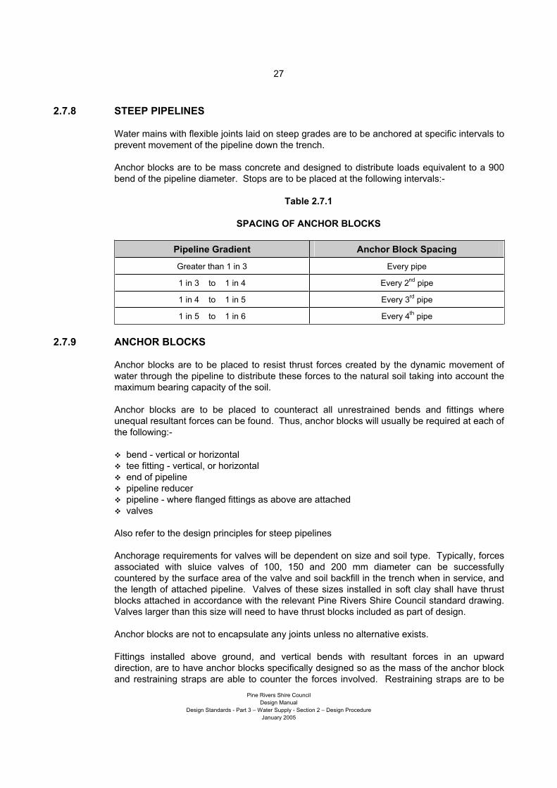
2.7.8 STEEP PIPELINES
Water mains with flexible joints laid on steep grades are to be anchored at specific intervals to
prevent movement of the pipeline down the trench.
Anchor blocks are to be mass concrete and designed to distribute loads equivalent to a 900
bend of the pipeline diameter. Stops are to be placed at the following intervals:-
Table 2.7.1
SPACING OF ANCHOR BLOCKS
Pipeline Gradient Anchor Block Spacing
Greater than 1 in 3 Every pipe
1 in 3 to 1 in 4 Every 2nd
pipe
1 in 4 to 1 in 5 Every 3rd
pipe
1 in 5 to 1 in 6 Every 4th
pipe
2.7.9 ANCHOR BLOCKS
Anchor blocks are to be placed to resist thrust forces created by the dynamic movement of
water through the pipeline to distribute these forces to the natural soil taking into account the
maximum bearing capacity of the soil.
Anchor blocks are to be placed to counteract all unrestrained bends and fittings where
unequal resultant forces can be found. Thus, anchor blocks will usually be required at each of
the following:-
bend - vertical or horizontal
tee fitting - vertical, or horizontal
end of pipeline
pipeline reducer
pipeline - where flanged fittings as above are attached
valves
Also refer to the design principles for steep pipelines
Anchorage requirements for valves will be dependent on size and soil type. Typically, forces
associated with sluice valves of 100, 150 and 200 mm diameter can be successfully
countered by the surface area of the valve and soil backfill in the trench when in service, and
the length of attached pipeline. Valves of these sizes installed in soft clay shall have thrust
blocks attached in accordance with the relevant Pine Rivers Shire Council standard drawing.
Valves larger than this size will need to have thrust blocks included as part of design.
Anchor blocks are not to encapsulate any joints unless no alternative exists.
Fittings installed above ground, and vertical bends with resultant forces in an upward
direction, are to have anchor blocks specifically designed so as the mass of the anchor block
and restraining straps are able to counter the forces involved. Restraining straps are to be
Page 32
28
Pine Rivers Shire Council
Design Manual
Design Standards - Part 3 – Water Supply - Section 2 – Design Procedure
January 2005
suitable for long term burial in all ground conditions and capable of retaining their required
restraining capacity over the life of the pipeline.
Downward and horizontal forces are to be transferred into the undisturbed natural soil by
providing an end surface area of the anchor block that distributes the forces at the not more
than the bearing capacity of the soil.
Care is to be taken that thrust forces are not transferred to undisturbed soil of insufficient
depth (width) to carry the applied load. An example of this may be where a thin undisturbed
wall exists between the designed water main trench and a recent adjacent parallel trench. In
such cases, the pipeline is to be laid at a greater depth to provide bearing capacity against
undisturbed soil.
The designer is also required to consider the possibility of future construction of infrastructure
in the area behind thrust areas along the pipeline and, where likely, design the water main to
be installed at a greater depth to ensure bearing capacity is maintained against undisturbed
soil.
Thrust forces associated with pipework and fittings installed inside or through pits and
chambers may be transferred into the walls of the pit or chamber and distributed to the
surrounding ground. To ensure this, flanges shall be installed on all pipework carrying thrust
which penetrates the walls of pits. Pit walls carrying thrust forces are to be designed to cope
with these forces.
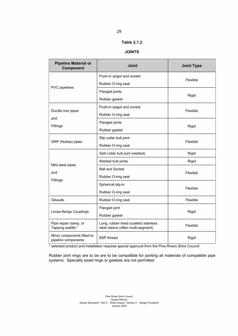
2.7.10 JOINTS
Joints in pipes may be designed as flexible joints or rigid joints.
Specialised joint systems may be required for interconnection of pipelines to some existing
infrastructure, or during maintenance or repair of the pipeline.
Loose flange couplings which rely on set–screws for retention on pipe barrels with will not be
permitted.
Page 33
29
Pine Rivers Shire Council
Design Manual
Design Standards - Part 3 – Water Supply - Section 2 – Design Procedure
January 2005
Table 2.7.2
JOINTS
Pipeline Material or
ComponentJoint Joint Type
Push-in spigot and socket
Rubber O-ring seal Flexible
PVC pipelines Flanged joints
Rubber gasket Rigid
Push-in spigot and socket
Rubber O-ring seal FlexibleDuctile iron pipes
and
FittingsFlanged joints
Rubber gasket Rigid
GRP (Hobas) pipes Slip collar butt joint
Rubber O-ring seal Flexible
Split collar butt joint (welded) Rigid
Welded butt joints Rigid
Ball and Socket
Rubber O-ring seal Flexible
Mild steel pipes
and
Fittings
Spherical slip-in
Rubber O-ring seal Flexible
Gibaults Rubber O-ring seal Flexible
Loose-flange Couplings Flanged joint
Rubber gasket Rigid
Pipe repair clamp, or
Tapping saddle *
Long, rubber lined (coated) stainless
steel sleeve (often multi-segment) Flexible
Minor components fitted to
pipeline components BSP thread Rigid
* selected product and installation requires special approval from the Pine Rivers Shire Council
Rubber joint rings are to be are to be compatible for jointing all materials of compatible pipe
systems. Specially sized rings or gaskets are not permitted.
Page 34
30
Pine Rivers Shire Council
Design Manual
Design Standards - Part 3 – Water Supply - Section 2 – Design Procedure
January 2005
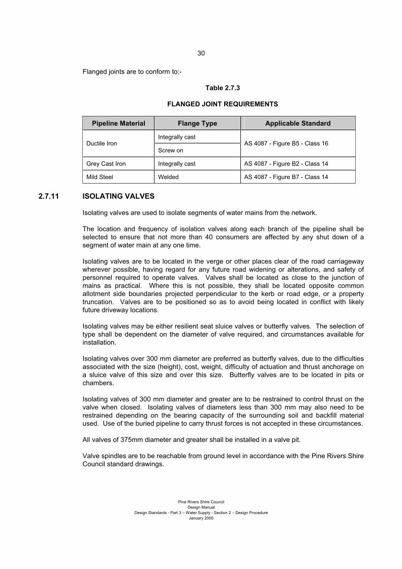
Flanged joints are to conform to:-
Table 2.7.3
FLANGED JOINT REQUIREMENTS
Pipeline Material Flange Type Applicable Standard
Integrally cast Ductile Iron
Screw on AS 4087 - Figure B5 - Class 16
Grey Cast Iron Integrally cast AS 4087 - Figure B2 - Class 14
Mild Steel Welded AS 4087 - Figure B7 - Class 14
2.7.11 ISOLATING VALVES
Isolating valves are used to isolate segments of water mains from the network.
The location and frequency of isolation valves along each branch of the pipeline shall be
selected to ensure that not more than 40 consumers are affected by any shut down of a
segment of water main at any one time.
Isolating valves are to be located in the verge or other places clear of the road carriageway
wherever possible, having regard for any future road widening or alterations, and safety of
personnel required to operate valves. Valves shall be located as close to the junction of
mains as practical. Where this is not possible, they shall be located opposite common
allotment side boundaries projected perpendicular to the kerb or road edge, or a property
truncation. Valves are to be positioned so as to avoid being located in conflict with likely
future driveway locations.
Isolating valves may be either resilient seat sluice valves or butterfly valves. The selection of
type shall be dependent on the diameter of valve required, and circumstances available for
installation.
Isolating valves over 300 mm diameter are preferred as butterfly valves, due to the difficulties
associated with the size (height), cost, weight, difficulty of actuation and thrust anchorage on
a sluice valve of this size and over this size. Butterfly valves are to be located in pits or
chambers.
Isolating valves of 300 mm diameter and greater are to be restrained to control thrust on the
valve when closed. Isolating valves of diameters less than 300 mm may also need to be
restrained depending on the bearing capacity of the surrounding soil and backfill material
used. Use of the buried pipeline to carry thrust forces is not accepted in these circumstances.
All valves of 375mm diameter and greater shall be installed in a valve pit.
Valve spindles are to be reachable from ground level in accordance with the Pine Rivers Shire
Council standard drawings.
Page 35
31
Pine Rivers Shire Council
Design Manual
Design Standards - Part 3 – Water Supply - Section 2 – Design Procedure
January 2005
Reticulation Mains
Isolation valves are to be installed on all branches of any pipeline junction (tee, cross or wye
etc.) in the reticulation network.
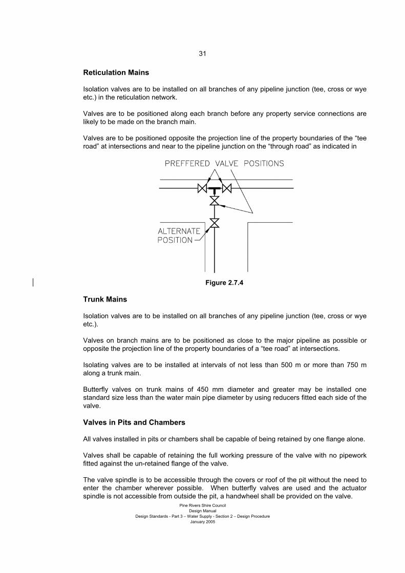
Valves are to be positioned along each branch before any property service connections are
likely to be made on the branch main.
Valves are to be positioned opposite the projection line of the property boundaries of the “tee
road” at intersections and near to the pipeline junction on the “through road” as indicated in
Figure 2.7.4
Trunk Mains
Isolation valves are to be installed on all branches of any pipeline junction (tee, cross or wye
etc.).
Valves on branch mains are to be positioned as close to the major pipeline as possible or
opposite the projection line of the property boundaries of a “tee road” at intersections.
Isolating valves are to be installed at intervals of not less than 500 m or more than 750 m
along a trunk main.
Butterfly valves on trunk mains of 450 mm diameter and greater may be installed one
standard size less than the water main pipe diameter by using reducers fitted each side of the
valve.
Valves in Pits and Chambers
All valves installed in pits or chambers shall be capable of being retained by one flange alone.
Valves shall be capable of retaining the full working pressure of the valve with no pipework
fitted against the un-retained flange of the valve.
The valve spindle is to be accessible through the covers or roof of the pit without the need to
enter the chamber wherever possible. When butterfly valves are used and the actuator
spindle is not accessible from outside the pit, a handwheel shall be provided on the valve.
Page 36
32
Pine Rivers Shire Council
Design Manual
Design Standards - Part 3 – Water Supply - Section 2 – Design Procedure
January 2005
2.7.12 HYDRANTS AND HYDRANT POINTS
Hydrants are positioned along water mains for the primary purpose of drawing water for fire
fighting. Hydrants also serve other functions such as:-
air entry and exit points by opening the hydrant during emptying and filling of mains
scouring or emptying of mains by opening the hydrant
pressure testing of mains (with the hydrant removed)
injection point for sterilisation of mains (with the hydrant removed)
insertion and removal point for swabs to clean pipelines
taking water by licensed persons
As hydrants serve these other purposes, the hydrant tee shall branch off from the obvert of
the main. In any case, the tee shall always be fitted such that a rising grade is maintained
from the obvert of the main to the hydrant. Hydrants are to be positioned in the verge or other
places clear of the road carriageway wherever possible, having regard for any future road
widening or alterations.
Hydrants are to be installed in an approved hydrant box and cover and their positions marked
in accordance with the Pine Rivers Shire Council requirements.
Hydrants are to be positioned opposite common allotment side boundaries projected
perpendicular to the kerb or road edge, or a property truncation. Hydrants are not to be
positioned on deflections in property frontages. Hydrants are to be positioned so as to avoid
being located in conflict with likely future driveway locations.
Reticulation Mains
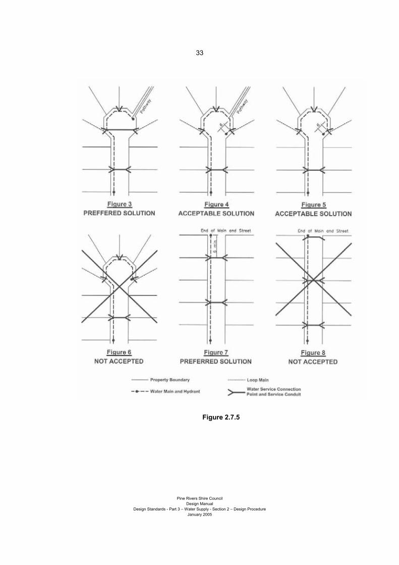
Hydrants are to be installed along all mains at a spacing of not more than 80 m.
A hydrant shall be installed at the “end” of each main, a minimum distance of 6 m beyond the
last property service connection point. Hydrants on the ends of reticulation are to be fitted on
to a ducks-foot or hydrant bend.
Where a loop main is provided, the hydrant will be installed as follows. The actual position
will depend on the location available for connection of the loop main and the location of the
last property service connection.
Loop Mains less than 100 mm diameter - on the reticulation main end 6 m minimum after
the last property connection point, or immediately after the connection point for the loop
main.
Loop Mains 100 mm diameter – on the reticulation main end 6 m minimum after the last
property connection point, or immediately before interconnection of the loop main.
Page 37
33
Pine Rivers Shire Council
Design Manual
Design Standards - Part 3 – Water Supply - Section 2 – Design Procedure
January 2005
Figure 2.7.5
Page 38
34
Pine Rivers Shire Council
Design Manual
Design Standards - Part 3 – Water Supply - Section 2 – Design Procedure
January 2005
Trunk Mains
Where trunk mains are located in areas where existing reticulation mains are in place,
hydrants are not required on the trunk main for fire fighting purposes.
Thus, the location and spacing of hydrants can be selected to suit their other functions such
as air entry, testing and sterilisation points.
Where there are no reticulation mains in place, hydrants shall be installed on the trunk main at
a spacing of:-
not more than 200 m where the Pine Rivers Shire Council water reticulation and planning
documents indicate future reticulation mains in the area; or
not more than 80 m where the Pine Rivers Shire Council water reticulation and planning
documents indicate there to be no future reticulation mains in the area.
Trunk mains are divided into segments by the installation of section valves. Air entry and
release points and scour outlets may be provided by hydrants, as discussed in other sections
of this document.
Hydrants can be positioned on a branch offset from the through main to position the hydrant
in the verge or other location clear of road carriageway.
2.7.13 LINE ENDS
Pipelines are to end with either an:-
end cap - fitted to a pipe spigot
end plug - fitted to a pipe socket
blank flange - fitted to a flanged fitting or pipe special
hydrant tee - and associated fittings
Ends are to have an accompanying thrust block or be retained on a flanged pipe or special
fitting as described below.
Reticulation Mains
Wherever possible, reticulation mains are to be designed as a loop service connecting with
another main.
Permanent ends of mains are to end with a hydrant bend, hydrant (and associated fittings)
and thrust block,
Temporary ends to water mains which are intended to be extended as a future stage of
development are to end with a hydrant tee, hydrant (and associated fittings) and thrust block,
Refer to Figure 2.7.5, Figures 3 to 8 for details of solutions.
Page 39
35
Pine Rivers Shire Council
Design Manual
Design Standards - Part 3 – Water Supply - Section 2 – Design Procedure
January 2005
Trunk Mains
Trunk mains may be reduced in diameter to transition to reticulation mains or terminate at
another trunk main.
Trunk mains terminating in an end usually represent staged construction requiring future
extension. In these circumstances, a section valve is to be installed near to the end of the
line. This valve can be manipulated closed to permit connection of the future extension
without having to close down operation of the whole of the existing main.
All temporary ends on trunk mains (mains that are to extend in the future) shall end with a
flanged end cap fitted to a pipe special with a thrust flange. The thrust flange is to be
captured in a suitably designed thrust block constructed across the trench.
This system allows the future extension to be joined to the existing main without the need to
remove a large thrust block at an end cap. The new main can be joined to the existing main
with a minimum length of untested and unsterilised pipeline.
2.7.14 AIR RELEASE AND AIR ENTRY
For pressure mains to function effectively, all air must be evacuated from the main following
initial post construction fill and any maintenance on the main. Under some conditions, air can
build up in mains from the release air dissolved in water. Entrapped air can inhibit efficient
pumping and create water hammer in mains. Similarly, when mains are being emptied,
unless air can be admitted into the pipeline, vacuum pressures can build up to the extent that
pipes may collapse.
Air release points are installed at the high points along water mains to permit the venting of
built-up air in the mains. These points are also used to permit the entry of air.
To address these issues, air release and entry points shall be fitted with a combination of air
valves allowing air entry and exhaust or a single double-acting air valve that provides both
capabilities.
Air valves shall be sized according to the Pine Rivers Shire Council standards, the specific
characteristics of to particular pipeline and in accordance with manufacturer’s specifications.
Air valves are to be fitted on to an off-take tee, usually rising vertically from the obvert of the
main. In constrained and special circumstances a scour tee may be fitted with the branch
positioned off the obvert of the main. Branch pipework shall be installed to ensure that a
rising grade is maintained to the air release valve.
A service valve (section valve) in the form of a butterfly valve or gate valve shall be positioned
immediately below every air valve (or on the branch pipework) to permit servicing of the air
valve. The service valve shall be fitted in a readily accessible position to workers at ground
level without need for excavation. The valve is to be fitted in a manner that retains the valve
permanently in place and the main operational with the air valve removed.
Air from the air valve shall be released to the atmosphere through suitable pipework.
Exhausted air shall not be permitted to build up in a sealed pit.
Page 40
36
Pine Rivers Shire Council
Design Manual
Design Standards - Part 3 – Water Supply - Section 2 – Design Procedure
January 2005
Reticulation Mains
Air valves are to be positioned on every high point along all reticulation mains of 250 mm
diameter and greater. An air valve shall also be installed on the end of any reticulation main
in this size range where the end of the main is the highest point on the main.
Air valves are not considered necessary on reticulation mains less than 250 mm diameter.
Trunk Mains
Air valves are to be positioned on every high point along all trunk mains.
Trunk mains are divided into segments by the installation of section valves. Air entry and
release points must be provided at suitable locations on each segment of the main for
effective emptying and filling.
Where air valves are not necessary along sections of main for optimum in-service
performance of the main, hydrant points may be used to allow air release or entry when filling
or emptying of the main or section of main.
2.7.15 SCOUR POINTS
Scour points are required on water mains to permit controlled emptying of a main for
maintenance works and for flushing and cleaning of a main.
Scour points are to be located at the lowest points along a pipeline.
Reticulation Mains
Scour points are required on all reticulation mains of 250 mm diameter and greater, as
described below for trunk mains.
Scour points are not required on reticulation mains less than 250 mm diameter. Hydrants are
commonly used and are permitted for scouring purposes on reticulation mains below this size.
Hydrants shall be positioned at the lowest point of a reticulation main.
Trunk Mains
Scour points shall be incorporated into the design of all trunk water mains. Scours shall
consist of a tee branch aligned to the invert of the water main.
A valve is to be located on the tee, or along the outlet pipework close to the tee, but preferably
out of a road carriageway. Valves controlling scours are to be treated the same as isolating
valves.
The outlet pipework shall be extended from the branch to a suitable outlet point. Suitable
outlets for scour pipework are:-
stormwater catchpit
stormwater manhole
culvert wall or endwall – not discharging directly into a creek or stream
a manhole or chamber constructed for the purpose of pumping from
Page 41
37
Pine Rivers Shire Council
Design Manual
Design Standards - Part 3 – Water Supply - Section 2 – Design Procedure
January 2005
Outlets, especially those not discharging into a chamber, are to be carefully designed to
control the projection, disbursement and erosion effects caused by released water.
Trunk mains are divided into segments by the installation of section valves. Scouring points
are to be installed at the lowest point on each section of a main to permit emptying of the
main.
On occasions where a scour point may not be effective due to an outlet point of a suitable
level not being available, emptying of the main may be effected using a hydrant point, where
the contents can be pumped out.
2.7.16 CONNECTIONS TO EXISTING MAINS
The designer shall consider the requirements of connecting new work into the existing water
supply network. The underlying principles to be considered when designing connection works
shall include:-
minimisation of effects on major supply systems (reservoirs may need to be full if working
on major trunk mains)
minimisation of down-time of any segment of the existing water supply system
minimisation of disruption to consumers
ease of installation and/or pre-assembly of components (constructability)
minimisation of untested pipework
minimisation of wastage of water and materials (at the time and in the future)
dosing and removal of testing, flushing and superchlorinated disinfecting waters
Where a project is known to require future extension, or includes planned connection of future
mains at pre-determined locations, the designer shall include all components into the project
necessary to permit these future works to be carried out under the principles described
above.
The planned and designed-in allowance for future interconnection or extension of mains is
especially critical for works associated with the trunk main system. Disruption to this system
must be kept to an absolute minimum of time and number of occurrences due to effects on
potentially critical segments of the supply network.
This may require the designer to include:-
additional branch tees and associated valves and fittings etc. at key locations
pipeline ends restrained, in place of thrust blocks on end caps
continue pipework through walls of pits and chambers
2.7.17 MISCELLANEOUS FITTINGS
Bends
Socket – Socket and Spigot – Socket flexible joint bends and other fittings which generate a
resultant thrust are not to be installed less than 10 times the pipeline diameter apart. .
Flanged bends and fittings may be installed coupled together.
Page 42
38
Pine Rivers Shire Council
Design Manual
Design Standards - Part 3 – Water Supply - Section 2 – Design Procedure
January 2005
Couplings
Gibault couplings will be required to enable installation of fittings etc. in to existing pipelines.
They will also be used to permit the dismantling and removal of components from pits,
chambers and pipelines etc.
Loose-flange couplings may be used for similar purposes as gibaults, however are used
where there is limited space available for dismantling joints, and dismantling of flanged
components is required.
Neither gibaults nor loose flange couplings are considered capable of accommodating or
transferring thrust forces.
Thrust Flanges and Weep Flanges
Flanges are commonly used to transfer unresolved forces from the pipeline in to an anchor
block or chamber wall. The following types of flanges may be used for this purpose:-
special cast fitting integrally cast thrust flange
pipe special with welded thrust flange
pipe special with mechanically fastened thrust (weep, or puddle) flange
It is preferred that all cases be manufactured under controlled conditions by pipe of
component suppliers. In all cases, the thrust flange shall have dimensions and configurations
not less than their respective pipe or fitting standards required for ordinary flanges.
Weep flange configurations are the same as for thrust flanges, however are fitted to assist
with inhibiting the influx of groundwater in to below-ground chambers and do not need to
transfer thrust forces.
2.7.18 PROPERTY SERVICE CONNECTIONS
Property service connections are the length of pipework, including the fittings, stopcock and
meter, between the water main and the property boundary, which are maintained by the Pine
Rivers Shire Council. The property owner will connect their private water supply plumbing to
this pipework.
The configuration of property service connection pipework may take many forms depending
on the use of the land and quantity of water required. Details and diagrams for property
service connections are detailed in the Pine Rivers Shire Council standard drawings. Where
a hydrant and pretapped property service fitting are required at the same common property
boundary, the hydrant shall take priority. The pretapped fitting may be placed as close as
practicable to the hydrant in a position clear of potential future driveway locations, or on the
next common property boundary.
Pretapped property service fittings are to be installed for commercial and industrial properties
where they are serviced by mains of a diameter compatible with these fittings. The
requirement for a larger diameter property service connection will be considered as part of the
allotment owners’ assessment of their use of the site.
Hydraulic consultants sizing and designing property service connections shall consider
aspects of backflow prevention in their design.
Page 43
39
Pine Rivers Shire Council
Design Manual
Design Standards - Part 3 – Water Supply - Section 2 – Design Procedure
January 2005
Community Title Developments
The provision of water to community title developments will be made from one point on the
water supply network and supply metered at this point.
In larger community title developments managed by a single administrative body, a second
metered connection to the Pine Rivers Shire Council water supply network may be permitted
in the interests of providing a looped internal network and backup point of supply. Requests
for approval of this configuration are to be directed to the General Manager, Pine Water.
The metering arrangements for community title developments will be in accordance with the
relevant Pine Rivers Shire Council policy.
Connections to Reticulation Mains
On reticulation mains, pre-tapped property service fittings are to be installed into mains at the
time of construction of the water main (where these fittings are available to suit the pipe
diameters). Pre-tapped property service fittings are to be the same diameter as the water
main. Where pre-tapped fittings are not available to suit the pipe diameters, alternate fittings
are not required.
Where pre-tapped property service fittings are to be installed along the water main, the fittings
are to be positioned opposite property side boundaries and preferably on the opposite side
boundary to electrical and communication connections.
Property service connections may only be made to reticulation mains.
Connections to Trunk Mains
Connections to trunk mains may only be considered where special circumstances exist, can
be demonstrated and with approval from the General Manager, Pine Water.
Under these circumstances, the Pine Rivers Shire Council may require the developer to
supply fittings for the tapping of the water main.
2.7.19 SERVICE CONDUITS
Conduits are to be provided under roadways and hard surfaced areas to facilitate the
installation of property service connections without excavation. Conduits are to extend behind
the kerb and channel and continue, without a break, under concrete pathways where these
are constructed on the verge adjacent to kerb and channel.
Service conduits are to be positioned and installed in accordance with the Pine Rivers Shire
Council standard drawings.
2.7.20 PIPEWORK IN PITS AND CHAMBERS
Pits or chambers are usually required for the installation of pressure reducing valves, and
larger section valves where butterfly valves are employed, or for other special installations.
Page 44
40
Pine Rivers Shire Council
Design Manual
Design Standards - Part 3 – Water Supply - Section 2 – Design Procedure
January 2005
Location
It is preferable for pits and chambers to be located clear of the existing and future road
carriageway wherever possible. However it is acknowledged this may not be possible in
many circumstances.
Where a pit must be positioned within a road carriageway, preference should be given to
locating it: -
clear of an intersection or the turning path of large/heavy vehicles through an intersection
in the shoulder clear of any driven lane
in, or across, one driving lane only
A pit shall not be installed across the line of kerb and channel between the road carriageway
and verge.
Pits are to finish level with their surrounding surface, or design future surface levels, unless
their design configuration requires otherwise.
Pits are to include a sump and, wherever possible, this shall connect to a free-draining outlet.
Flotation
In areas where there is a high water table, all pits are to be checked and designed to ensure
flotation of the pit will not occur.
In determining flotation characteristics, the designer may include the pit and all pipework
permanently cast into the pit i.e. pipework penetrating the walls.
Pipework and fittings which may be removed from the pit and pipework in trenches leading to
and from a pit may not be included in any calculations to assist in the prevention of flotation.
Ends
Where a branch line terminates at a pit, and this line is to be extended in the future, a valve is
to be installed on the branch line allowing the future extension to be joined to the existing line
without interruption to supply.
The end branch is to be brought through the pit wall and terminated outside the pit with a
suitable end cap, plug, or blank flange (see, also, “line ends”).
Valves
Where the pit is for installation of an on-line section valve, the layout must accommodate
thrust and dismantling for removal of the valve and/or other pipeline fittings. The valve shall
be retained on the pipework from the direction of flow.
Where the pit accommodates a tee or cross branch, valves are to be positioned on each
branch line. A valve cannot be installed on each pipeline leg within one pit as thrust forces
cannot be addressed whilst maintaining the ability to dismantle and remove components. A
minimum of two branch valves shall be included in the pit. Section valves, if in close proximity
(less than 100 m away) can serve as branch valves. In other circumstances, another pit to
Page 45
41
Pine Rivers Shire Council
Design Manual
Design Standards - Part 3 – Water Supply - Section 2 – Design Procedure
January 2005
accommodate a branch valve must be located within this distance.
Thrust
Refer to the section dealing with anchor blocks.
Jointing
Pipework located inside pits shall be designed to permit dismantling for maintenance and
servicing of valves and for future modification to pipework.
Fittings such as gibault joints, which permit movement of fittings for the separation of flanges,
shall be strategically incorporated into the pipework layout.
Pipework, or pipe specials over which gibaults joints are to be installed shall be designed so
that the complete length of the gibault barrel and one ring (collar) is able to be accommodated
fully on one of the components being joined.
Access
Access into pits and chambers is to be designed to suit:-
manipulation (operation) of valves without the need for personnel to enter the pit
placement of a portable de-watering pump within a sump in the pit from the ground level or
pit surface level
personnel access
access which permits maintenance of and removal of serviceable components from the pit
e.g. valves, pressure reducing valves, fittings etc.
Provisions for personnel access must be in accordance with Occupational Health and Safety
requirements for access space and include a ladder or step irons permanently installed in the
pit.
Pits may have a cast concrete top incorporating suitably sized access openings strategically
located to suit the above criteria or a top cover that is fully removable. Access covers located
in a traffic area (not only roads) are to be Class D to AS 3996.
2.7.21 WATER DRAW-OFF POINTS
In areas where new park residential, special residential and future rural living areas are
developed on the fringe of the water supply network, the Pine Rivers Shire Council may
require the installation of a designated point to permit the drawing-off of water from the main.
Selection of the site for the draw-off point should consider the following criteria:-
be along a road of highest order classification possible (Refer Design Standards for
Roadworks)
be easily accessible and safe for use by water tanker trucks
be relatively remote from residences and commercial properties
preferably be on, or near to an end of a reticulation pipeline
be within 500 metres of a suitable safe truck turning or manoeuvring area
preferably be on a main of 200mm diameter
Page 46
42
Pine Rivers Shire Council
Design Manual
Design Standards - Part 3 – Water Supply - Section 2 – Design Procedure
January 2005
The facilities to be provided as part of the draw-off facility include:-
a paved and sealed pull-off facility clear of the through road driving lanes, suitable for a
heavy rigid vehicle, constructed similar to a bus bay, or
a paved and sealed pull-off facility within a parking area of a sealed road carriageway clear
of through traffic, or
a safe truck turning or manoeuvring area is to be provided where this is not available within
500, and
a hydrant is available or installed within 5m reach of the pull-off area
attention is to be paid to ensure safe operation of the through road, and safe turning to and
from the through road, including road geometry, sight distance, passing lanes etc.
branch water mains installed solely for the purpose of supply to the filling point may be
100mm diameter
2.7.22 TELEMETRY
The Pine Rivers Shire Council may require telemetry control to be installed on some water
supply installations, for example pressure reducing valve installations, pumping facilities and
reservoirs.
Advice is to be sought from the Pine Water Section of Pine Rivers Shire Council on the
standard installation arrangements required.
2.7.23 TESTING
Water mains shall be tested in accordance with the requirements and procedure described in
the Pine Rivers Shire Council specifications for water supply works.
The designer shall consider the specific requirements associated with testing of the water
mains and include these features in the pipeline design. This will include installation of places
to fill and drain the main and for the connection of testing equipment.
2.7.24 FLUSHING AND STERILISATION
Water mains shall be flushed and sterilised in accordance with the requirements and
procedure described in the Pine Rivers Shire Council specifications for water supply works.
Super-chlorinated water shall be disposed of in a way that will not cause any harmful effects
to, or degradation of, the flora or fauna and streams or waterways, including erosion.
Disposal will require dilution or neutralisation of the super-chlorinated water.
The designer shall consider the specific requirements associated with this work and include
these features in the pipeline design. This will include installation of places to fill and drain the
main and for the dosing of the disinfecting agents.
Any cross connection, temporary or otherwise, to the live system while sterilising is to be fitted
with backflow prevention in accordance with AS 3500.