75
DESIGN, INSTALLATION AND MAINTENANCE MANUAL OF AEROSOL PYROSOL FIXED AEROSOL FIRE EXTINGUISHING SYSTEM P/N PyroSol MANUAL FEBRUARY 2020

DESIGN, INSTALLATION AND MAINTENANCE
MANUAL OF AEROSOL PYROSOL FIXED AEROSOL
FIRE EXTINGUISHING SYSTEM
P/N PyroSolMANUAL
FEBRUARY 2020

1
P/N PyroSolMANUAL REV. 001 FEBRUARY 2020
PyroSol Technical Information
Document history
Revision Date Modification / Change
001 12-02-2020 Design / JA

2
P/N PyroSolMANUAL REV. 001 FEBRUARY 2020
PyroSol Technical Information
TABLE OF CONTENT
Introduction 7 Purpose
Trade mark and Patent
1. Use and application 8
2. Safety Summary 9 2.1 General
2.1.1 Health Effects
2.2 Hazards to Personnel
2.2.1 Potential Hazards
2.2.2 Pre-discharge alarms and time delay
2.2.3 Egress
2.2.4 Reduced visibility
2.2.5 Toxicity
2.2.6 Thermal Hazards
2.3 Environmental Factors
2.4 Compatibility with other agents
3. Specifications, plans and approvals 12
3.1 Working documents
3.1.1 Specifications
3.1.2 Working plans
3.1.3 Approval of Plans
3.2 Enclosure
3.2.1 Loss of Agent
3.3 Condensed Aerosol System Agent Supply
3.3.1 Quantity
3.4 Design application density
3.4.1 Determining Design Application Density
3.4.2 Fuel types, table 01 EN-2 / table 01 NFPA
3.4.3 Standard quantity calculation
3.4.4 Additional design factors

3
P/N PyroSolMANUAL REV. 001 FEBRUARY 2020
PyroSol Technical Information
3.5 Duration of Protection
3.5.1 Discharge time
3.5.2 Extended discharge
3.5.3 Safety vents
3.5.4 Generator Choice and location
3.6 Distribution verification
4. General Information 22
4.1 Minimum safe distances
4.1.2 Minimum safe distances for personnel
4.1.3 Minimum safe distances for combustibles
4.2 Safety requirements
4.3 Electrical clearances
4.4 Precautions while handling the PYROSOL generators
4.5 Storage and transport
4.6 Storage conditions
4.6.1 Environmental operation conditions
4.7 Replacement & removal from service
5. Detection, actuation, alarm and control systems 26 5.1 General
5.2 Raceways
5.3 Automatic detection
5.4 Operating devices
5.5 Fire alarm control panel
5.6 Operating alarm and indicators
5.7 Warning devices
5.8 Abort switches
5.9 Alarm indicating failure
5.10 Waring and instruction signs
5.11 Pre-discharge alarms and time delays
5.12 Unwanted system operation
6. Components 31
6.1 General
6.2 PYRO ENGINEERING CORP. PYROSOL aerosol generator installation procedure

4
P/N PyroSolMANUAL REV. 001 FEBRUARY 2020
PyroSol Technical Information
7. System Layout
32
8. Total flooding system commissioning 33 8.1 Installation acceptance
8.1.1 Basic checks
8.1.2 Review enclosure
8.1.3 Review electrical components
8.1.3.1 Wiring
8.1.3.2 Auxiliary Functions
8.1.3.3 Locations
8.1.4 Preliminary functional tests
8.1.4.1 System functional test
8.1.4.2 Secondary power test
8.1.4.3 Return of system
9. Inspection, Maintenance test, training and safety 37 9.1 Regular inspection
9.2 Periodic inspection
9.3 Maintenance
9.4 Penetrations
9.5 Condensed aerosol generator inspection
9.6 Training
9.7 Safety
9.8 Residue Removal
10. Disposal of discharged aerosol agent 41 10.1 Guidelines to clean the residue
10.2 Dismantling condensed aerosol generators
10.3 Waste and environment
11. Replacement parts 43
11.1 Label part numbers
12. Appendix A; MSDS 44
13. Appendix B; Info sheets PYROSOL generators 52
13.1 PYROSOL A50

5
P/N PyroSolMANUAL REV. 001 FEBRUARY 2020
PyroSol Technical Information
13.2 PYROSOL A100
13.3 PYROSOL A200
13.4 PYROSOL A500
13.5 PYROSOL A1000
13.6 PYROSOL A5000
14. Appendix C; Fire Classes EN-2 71
15. Appendix D; Fire Classes NFPA 71
16. Appendix E; Referenced publications 72
17. Appendix F; Definitions 73

6
P/N PyroSolMANUAL REV. 001 FEBRUARY 2020
PyroSol Technical Information
Foreword
This manual is written for those who design, install and maintain PYRO ENGINEERING CORP. PYROSOL
aerosol fire suppression systems. This document contains design, installation, operation and
maintenance information for this PYROSOL fire suppression system.
PYRO ENGINEERING CORP. accepts no responsibility for applications of any systems other than those
addressed in this manual. The technical data in this manual is restricted stringently for information
purposes only. PYRO ENGINEERING CORP. believes this data to be accurate but it’s published and
presented without any guarantee or warranty of any kind. PYRO ENGINEERING CORP. denies any liability
for any use that may be made of the data and information contained herein by any and all other parties.
PYRO ENGINEERING CORP. , PYROSOL aerosol fire suppression systems are to be designed, installed,
inspected, maintained and tested by qualified, trained and certified personnel in accordance with the
following:
- NFPA 2010, and any other applicable NFPA standard
- UL-2775
- BRL-23001/4
- ISO-15779
- CEN/TR-15276
- All instructions, limitations contained in this manual
- Storage, handling and transportation shall be performed by qualified and trained personnel in
accordance with local requirements.
Questions in respect to the information presented in this manual should be addressed to:
Pyro Engineering Corp. Fire Fighting Equipment
PYRO ENGINEERING CORP
409-11, 38-9, Digital road 31-gil, Guro-gu
Seoul, 08376
Republic of Korea
Tel: +82-2-6959-9068
Introduction

7
P/N PyroSolMANUAL REV. 001 FEBRUARY 2020
PyroSol Technical Information
PYRO ENGINEERING CORP. , PYROSOL aerosol
fire suppression systems are designed for total flooding applications in accordance with established
design criteria. Applications methods, design criteria and restrictions are contained within this manual. In
any situation not specified in this manual, the application and the installation of the system must be in
accordance with the applicable standard. All installations must meet the requirements of the local
authorities.
Purpose
This guide is intended for use by those with the properly mandated authority of purchasing, designing,
installing, operating, and maintaining PYROSOL aerosol fire extinguishing systems. This guide provides
information designed to supplement PYRO ENGINEERING CORP. -certified training.
Authorized training is required to design, install, operate and maintain the PYROSOL aerosol system!
Do not attempt to install or service this system if you have not been provided with authorized training!
PYRO ENGINEERING CORP. assumes no liability resulting from misuse of the information provided
herein.
The requirements of this manual are deemed necessary to provide adequate protection from injury,
death, and loss of property from improper installation or fire.
Trademark and Patent
The PYROSOL Powdered Aerosol Fire Extinguishing products described in this document are the property
of PYRO ENGINEERING CORP. Fire Fighting Equipment.
No part of the hardware, software, or documentation may be reproduced, transmitted, transcribed,
stored in a retrieval system, or translated into any language or computer language, in any form or by any
means, without prior written permission of PYRO ENGINEERING CORP. .
PYRO ENGINEERING CORP. reserves the right to make changes to any products described herein to
improve reliability, function, or design. PYRO ENGINEERING CORP. reserves the right to revise this
document from time to time in content hereof with no obligation to notify any persons of revisions or
changes. PYRO ENGINEERING CORP. does not assume any liability arising out of the application or any
use of any product or circuit described herein, neither does it convey license under its patent rights or the
patent rights of others.
PYROSOL units are not field-repairable. Do not attempt to modify or temper the unit structure as it shall
decrease discharge efficiency and lower design application density. Modified units are not subject to
repair or exchange under PYRO ENGINEERING CORP. product warranty.
PYROSOL aerosol fire extinguishing systems for total flooding applications is a registered trademark of
PYRO ENGINEERING CORP. .

8
P/N PyroSolMANUAL REV. 001 FEBRUARY 2020
PyroSol Technical Information
1. Use and Application
PYROSOL aerosol suppression systems are effective in extinguishing Class A, B, and C fires. PYROSOL
aerosol suppression systems provide an efficient and effective means to extinguish gas and liquid fires,
burning solid substances, burning substances derived from hydrocarbons (natural gas, oil products,
flammable lubricants, etc.), as well as fires in electrical equipment with an operating voltage not
exceeding 40,000 Volts.
PYROSOL aerosol suppression systems shall not be used on metal fires, on substances generating self-
sustaining combustion, and on the following substances unless they have been tested to the satisfaction
of the authority having jurisdiction and/or proven by experimental testing carried out by a third party
laboratory.
• Deep seated fires in Class A materials
• Class D fires:
▪ D1 - light metals (aluminum - Al; magnesium - Mg Titanium ...)
▪ D2 - alkali metals (potassium - K; sodium - Na; lithium - Li ...)
▪ D3 - organic-metallic compounds (methyl magnesium chloride - CH3MgCl; methyl
magnesium iodide - CH3MgCl; triethyl aluminum - (C2H5)3Al ...)
▪ Metal hydrides (aluminum hydride - AlH3) lithium hydride - LiH ...)
▪ Reactive metals such as sodium, potassium, lithium, magnesium, titanium,
uranium, and plutonium.
▪ Metal powders (magnesium, titanium, etc.)
• Chemical compounds containing oxidizers such as sodium chlorate or sodium nitrate.
The above list may be not exhaustive. Contact PYRO ENGINEERING CORP. or your local PYRO
ENGINEERING CORP. distributor if additional information is required.
The PYROSOL aerosol generators shall not be employed at less than the minimum safe distances specified
in the present guide (see the aerosol generator datasheets for details).
The minimum safe distance between the PYROSOL aerosol generator discharge ports and personnel shall
be based on an aerosol agent discharge temperature, at that distance, not exceeding 75°C (167°
F). See Appendix C for generator datasheets and minimum safe distance information.
The minimum safe distance between the PYROSOL aerosol generator discharge ports and combustible
materials shall be based on an aerosol agent discharge temperature, at that distance, not exceeding
200°C (392° F). See Appendix C.
9
P/N PyroSolMANUAL REV. 001 FEBRUARY 2020
PyroSol Technical Information
The total flooding PYROSOL aerosol suppression
system shall be installed in enclosures protecting the hazards that allows the specific agent design
application density to be achieved and maintained for the specified period of time.
Where the PYROSOL aerosol suppression agents are used in spaces containing sensitive equipment, the
potential adverse effects of condensed aerosol particulate residue shall be considered.
2. Safety Summary
For Material Safety Data Sheet refer to Appendix A.
2.1 General
PYROSOL aerosol suppression systems can potentially be hazardous to persons due to the mechanism of
aerosol dispersal. Unnecessary exposure to the aerosol, byproducts created by the interaction between
the aerosol and the fire, and the fire itself should be avoided.
2.1.1 Health Effects
The potential adverse health effects can range from:
• Hazards for humans related to the solid aerosol-forming compound has not been found.
• Hazards to humans related to the aerosol released by the reaction of the solid aerosol-forming
compound have not been established because the threshold limit values (TLVs) are not applicable.
However, it is reputed that hazards to humans are not present when the aerosol is applied as mandated
by this manual.
• Signs and symptoms related to the aerosol release phase are only referred to for acute exposure
and/or chronic overexposure. In a real life situation, the exposure to the generated aerosol will only
occur accidentally and the exposure time will be very short, as in the event of an accidental or
unexpected discharge when an occupant of the protected space has not evacuated previously. The
aerosol system shall be installed in normally unoccupied spaces and/or in spaces where occupants may
be present utilizing suitable safeguards.
2.2 Hazards to Personnel
2.2.1 Potential Hazards

10
P/N PyroSolMANUAL REV. 001 FEBRUARY 2020
PyroSol Technical Information
Potential hazards to be considered for individual
systems in the protected space and other areas where the aerosol agent can migrate are the following:
Thermal hazard:
The aerosol agent is discharged at temperatures that may be hazardous to personal health. Depending
on the needs of the installer, the temperature and minimum clearance from the discharge outlets are
specified by the generator data sheets. After release, the aerosol generators can be hot; protective gloves
shall be worn by personnel handling discharged aerosol generators immediately after release.
Reduced Visibility:
After activation, the aerosol agent reduces visibility during and after the release period.
Turbulence:
Release from discharge outlets is ejected at high speed and may cause enough turbulence inside the
protected space to move unsecured objects.
Noise:
The release of a system or aerosol generator may cause considerable noise, but is not detrimental to
occupant health.
Eye irritation:
Direct contact with the aerosol particulate being released by the system may result in irritation of the
eyes. Exposure of aerosol agent to the eyes should be avoided.

11
P/N PyroSolMANUAL REV. 001 FEBRUARY 2020
PyroSol Technical Information
2.2.2 Pre‐Discharge Alarms and Time Delay
Exposure to the aerosol agents shall be prevented by providing a warning of a pending release. A
delay prior to the release shall be calibrated to allow occupants to exit the protected space.
Predetermined exits shall be provided to assure safe egress of occupants in case of failure of the
pre-release alarm and/or time delay.
2.2.3 Egress
Predetermined egress shall be provided to allow the occupants to exit the protected space within the
time delay. The effects of reduced visibility during egress shall be considered.
2.2.4 Reduced Visibility
The discharged aerosol will cause occupants to evacuate the protected space under conditions of low
visibility. Appropriate safety measures shall be used so that occupants can evacuate safely. The safety
measures shall include, but are not limited to: goggles, floor mounted directional lighting, strobes, audio
devices, evacuation plans, and exit drills.
2.2.5 Toxicity
See the Material Safety Data Sheet (MSDS) contained in Appendix A and the information in section 2.2.1
of this guide.
2.2.6 Thermal Hazards
Aerosol generators shall not be employed at less than the listed minimum safe distance from occupants
and combustible materials. See the aerosol generator datasheets for minimum safe distance information.
Protective gloves shall be worn by personnel removing discharged aerosol generators.
2.3 Environmental Factors
Though aerosol extinguishing systems do not pose any significant environmental concern, the
unnecessary emission of aerosol shall be avoided. All phases of design, installation, testing, and
maintenance of aerosol extinguishing systems shall be undertaken with the goal of zero emission to the
environment.

12
P/N PyroSolMANUAL REV. 001 FEBRUARY 2020
PyroSol Technical Information
2.4 Compatibility with Other Agents
Unless specifically approved, systems employing the simultaneous release of different agents to protect
the same enclosed space shall not be permitted. Where uncorrelated extinguishing or suppression
systems are provided, and can operate prior to or during the hold time of the aerosol extinguishing
agent, the other agent(s) shall not affect the aerosol’s capabilities.
3. Specifications, Plans, and Approvals
3.1 Working Documents
The design of an PYROSOL aerosol-flooding suppression system shall be prepared only by a person
qualified to design extinguishing systems, in accordance with the advice of the authority having
jurisdiction.
Deviation from the working documents shall require the permission and agreement of the authority
having jurisdiction.
The working documents shall include, as a minimum requirement, the following:
3.1.1 Specifications
• Designation of the authority having jurisdiction,
• Differences from the standard to be permitted by the authority having jurisdiction,
• Design criteria,
• System sequence of operation,
• Functional testing to be performed after installation of the system,
• System owner/user training requirements.

13
P/N PyroSolMANUAL REV. 001 FEBRUARY 2020
PyroSol Technical Information
3.1.2 Working Plans
• Name of owner and identification of the occupant/user;
• Point of compass and symbol legend.
• Location of building, including address;
•Location and construction characteristics of protected enclosure walls and partitions; location of fire
walls.
• Enclosure cross-section, full height or schematic diagram, including raised access floor and suspended
ceiling;
• Description of occupancies and hazards to be protected; identification of enclosures normally occupied
• Description of enclosures/facilities/exposures surrounding the enclosure.
• Plan view of protected area showing enclosure partitions (full and partial height); detection, alarm, and
control system including all devices and schematic of wiring interconnection; end-of-line device locations;
location of controlled devices such as dampers and shutters; location of instructional signage.
• Type of condensed aerosol generators used; including nominal capacity expressed as agent solid
compound mass.
• Condensed aerosol design application density.
• Drawings indicating the location and distribution of condensed aerosol generators.
• Equipment list of materials showing device identification, model or part number, quantity and
description;
• Description of fire detection, actuation and control systems
• Enclosure pressurization report and venting calculations where applicable;
• Description of wire or cable used including classification, gauge [American Wire Gauge (AWG)],
shielding, number of strands in conductor, conductor material, and color coding schedule, with the
segregation requirements of various system conductors clearly indicated and the required method of
making wire terminations detailed.
• Description of the detector mounting.
• Scale drawing showing the layout of the annunciator panel graphics if required by the authority having
jurisdiction.

14
P/N PyroSolMANUAL REV. 001 FEBRUARY 2020
PyroSol Technical Information
• Complete step-by-step description of the
system sequence of operations including functioning of abort and maintenance disconnect switches,
delay timers, and emergency power shutdown.
• Point-to-point wiring schematic diagrams showing all circuit connections to the system control panel, to
the graphic annunciator panel and to external or add-on relays.
• Complete calculations to determine the size of backup batteries and method used to determine
number and location of audible and visual indicating devices and number and location of detectors.
• Minimum clearances to combustible materials and the means of egress.
• Details of any special features.
Information shall be submitted for approval to the authority having jurisdiction pertaining to the location
and function of:
• Detection devices,
• Operating devices,
• Auxiliary equipment,
• Electrical circuitry, if used.
• All the apparatus and devices used shall be identified.
• Any special features shall be explained.
• The as-built installation drawings and the instruction and maintenance guide that includes a full
sequence of operations.
• A full set of drawings and calculations shall be maintained on site.
3.1.3 Approval of Plans
Plans and calculations shall be approved prior to installation.
Where field conditions necessitate any change from approved plans, the change shall be approved prior
to implementation.
When such changes from approved plans are made, the working plans shall be updated to accurately
represent the system as installed.

15
P/N PyroSolMANUAL REV. 001 FEBRUARY 2020
PyroSol Technical Information
3.2 Enclosure
In the design of an aerosol-flooding extinguishing system, the area of the protected enclosure shall be
considered.
Fixed or non-closable openings in the protected enclosure shall be kept to a minimum.
3.2.1 Loss of Agent
To prevent loss of agent through openings to adjacent hazards or work areas, openings shall be
permanently sealed or equipped with automatic closures.
Where reasonable confinement of agent is not practicable, protection shall be expanded to include the
adjacent connected hazards or work areas or additional agent shall be introduced into the protected
enclosure using an extended discharge configuration.
Forced-air ventilating systems shall be shut down or closed automatically where their continued
operation would adversely affect the performance of the fire extinguishing system or result in
propagation of the fire.
Completely self-contained recirculation ventilation systems shall not be required to be shut down.
The volume of the ventilation system and associated ductwork shall be considered as part of the total
hazard volume when determining the quantity of agent.
The protected enclosure shall have the structural strength and integrity necessary to contain the agent
discharge.
If the developed pressures present a threat to the structural strength of the enclosure, venting shall be
provided to prevent excessive pressures.

16
P/N PyroSolMANUAL REV. 001 FEBRUARY 2020
PyroSol Technical Information
3.3 Condensed Aerosol System Agent Supply
3.3.1 Quantity
Primary condensed aerosol Agent Supply.
The primary aerosol agent supply shall be determined by calculating the required mass of the solid
aerosol forming compound needed to meet the design application density.
Reserve condensed aerosol Agent Supply.
Where required, a reserve aerosol agent supply shall consist of as many multiples of the primary agent
supply as the authority having jurisdiction considers necessary.
3.4 Design Application Density
3.4.1 Determining Design Application Density
The PYROSOL aerosol suppression application density shall be used in determining the minimum design
application density for a particular fuel (fire class). For combinations of fuels, the extinguishment value
for the fuel requiring the greatest aerosol design application density shall be used, unless specific tests
are made on the actual mixture.
Extinguishing application density is calculated by taking the mass of solid aerosol forming compound
necessary to extinguish a fire over the volume of the protected space in a test fire.
The design application density is calculated by adding 30 percent to the extinguishing design density.
Additional safety factors can be required depending on the specific characteristics of the hazard as
specified by this standard. The system designer can then calculate the amount of solid aerosol forming
material needed to achieve the design application density and thus protect a given space by applying the
formula in 3.4.3.

17
P/N PyroSolMANUAL REV. 001 FEBRUARY 2020
PyroSol Technical Information
3.4.2 Fuel Types
Table 01: Fire Classes EN2
Fire class Burning Materials
A Solids - surface fires only
Ordinary combustible or fibrous material such as wood, paper, fabric, coal,
leather, sugar, rubber and some plastics.
(not suitable for deep seated fires)
B Flammable liquids such as petrol, kerosene, alcohol, oil and paint thinners.
C Flammable gasses such as LPG, butane, acetylene, hydrogen, natural gas
and methane.
F Flammable unsaturated cooking oils in well-insulated cooking appliances,
located in commercial kitchens.

18
P/N PyroSolMANUAL REV. 001 FEBRUARY 2020
PyroSol Technical Information
Table 02: Fire Classes NFPA 2010 Fire class Burning Materials
A Solids - surface fires only
Ordinary combustible or fibrous material such as wood, paper, fabric, coal,
leather, sugar, rubber and some plastics.
(not suitable for deep seated fires)
B Flammable liquids and gas such as petrol, kerosene, alcohol, oil and paint
thinners.
C Electrical fires, Electrical hazards. Fires involving live electrical equipment
(e.g. computers, switchboards and power tools).

19
P/N PyroSolMANUAL REV. 001 FEBRUARY 2020
PyroSol Technical Information
3.4.3 Standard quantity calculation
The mass of condensed aerosol forming compound required shall be calculated from the following
formula:
where:
m = Total mass of aerosol required to protect the compartment in grams
V = Total volume if the protected enclosure / compartment
c = Application density required to extinguish the fire class in grams per cubic meters.
S = Safety factor of 30% according to CEN/TR 15276-1 and international standards.
3.4.4 Additional Design Factors
For the following (extraordinarily) situations extra correction coefficients(K) must be used to correct
to following effects:
o Leakage through enclosure openings
o Effects of altitude
o Effects of temperature
o Effects of ventilation
Fire class
Extinguishing application
Design application including
NFPA 30% Safety Factor
Class A fuels solid combustibles:
120 gr./m3
156 gr./m3
Class B fuels Flammable liquids:
110 gr./m3
143 gr./m3
M = V x c x S

20
P/N PyroSolMANUAL REV. 001 FEBRUARY 2020
PyroSol Technical Information
3.5 Duration of Protection
The aerosol agent design application density shall be maintained for the specified period of time to
prevent re-ignition of the fire before effective emergency action can be taken by trained personnel.
3.5.1 Discharge Time
For the aerosol generator discharge time, see the generator Data Sheets.
3.5.2 Extended Discharge
When an extended discharge is necessary to maintain the design application density for the specified
period of time, additional aerosol agent quantities shall be applied.
When an extended discharge is necessary, the rate shall be sufficient to maintain the desired factor for
the required hold time. In such applications the aerosol generators may be activated in sequence.
3.5.3 Safety Vents
When aerosol particulate is discharged into a closed volume, overpressure may be developed due to the
amount of gases generated and the effects of increased temperature of the atmosphere.
Later, the combined volume of aerosol and air will become greater than the initial room volume; the final
result will increase the pressure or will exhaust the excess volume through vent openings. The air
temperature is increased during the discharge, but will return to normal levels as heat is adsorbed by
solid surfaces in the room.
The designer and/or installer shall provide reliable calculations for venting requirements for each system,
if applicable, since experience has shown that most ordinary rooms have a sufficient leakage through
cracks around doors and windows, and a general porosity that will prevent noticeable pressure build up.
In rooms that may be sealed or close to being sealed, a safe vent area for low-strength structures can be
estimated on the basis of the discharge flow rate.

21
P/N PyroSolMANUAL REV. 001 FEBRUARY 2020
PyroSol Technical Information
3.5.4 Generator Choice and Location
The aerosol generators shall be suitable for the intended purpose and shall be placed within the
protected enclosure in compliance with the instruction and limitations contained in this guide with
regard to floor coverage, spacing, alignment, and thermal clearances.
The type of aerosol generators selected, their number, and their placement shall be such that the design
application density will be established in all parts of the hazard enclosure.
Condensed Aerosol Fire Extinguishing System Arrangement
The condensed aerosol generators and ancillary system components shall be arranged to allow easy
inspection and maintenance activities, minimizing the interruption of protection.
Condensed aerosol generators shall not be located where they can be mechanically damaged, exposed to
chemicals, or to adverse weather conditions which may render them inoperative.
Suitable protective provisions shall be adopted, if necessary.
Condensed aerosol generators shall be securely installed following the guidance given by this guide.
3.64 Distribution verification
Generator type Max. area (m2) Max. Height (m) Min. Height (m) Max. Throw (m)
A50 .80 1.27 .63 1.45
A100 1.21 1.51 .80 1.75
A200 2.01 2.01 1.00 2.30
A500 3.78 2.91 1.30 3.25
A1000 5.92 3.59 1.70 4.06
A5000 14.60 4.97 2.91 5.94
Generator type Max. area (ft2) Max. Height (ft) Min. Height (ft) Max. Throw (ft)
A50 8.61 4.17 2.07 4.76
A100 13.02 4.95 2.62 5.74
A200 21.64 6.59 3.28 7.55
A500 40.69 9.55 4.27 10.66
A1000 63.72 11.78 5.58 13.32
A5000 157.15 16.31 9.55 19.48

22
P/N PyroSolMANUAL REV. 001 FEBRUARY 2020
PyroSol Technical Information
4. General Information
4.1 Minimum Safe Distances
Condensed aerosol generators shall not be installed at less than the minimum safe distances as specified
in the condensed aerosol generator data sheets. The generator datasheets are in Appendix C of this
guide.
The minimum safe distance between the condensed aerosol generator casing and personnel shall be the
distance from the generator casing to where the temperature does not exceed 75°C (167°F) during and
after discharge.
The minimum safe distance between the condensed aerosol generator casing and combustible materials
shall be the distance from the generator casing to where the temperature does not exceed 200°C (392°F)
during and after discharge.
4.1.2 Minimum safe distance for Personnel:
Generator
type
Discharge stream Generator casing
Distance,
in
Distance,
cm
Max.
temp,
°F
Max.
temp,
°C
Distance,
in
Distance,
cm
Max.
temp,
°F
Max.
temp,
°C
A50 6 15 95 35 .25 0.6 96 35
A100 24 61 142 61 .25 0.6 142 61
A200 36 91 156 69 .25 0.6 166 74
A500 36 91 167 75 .25 0.6 81 27
A1000 36 91 140 60 .25 0.6 146 63
A5000 72 183 166 74 .25 0.6 139 59

23
P/N PyroSolMANUAL REV. 001 FEBRUARY 2020
PyroSol Technical Information
4.1.3 Minimum safe distance for Combustibles
Generator
type
Discharge stream Generator casing
Distance,
in
Distance,
cm
Max.
temp,
°F
Max.
temp,
°C
Distance,
in
Distance,
cm
Max.
temp,
°F
Max.
temp,
°C
A50 0 0 290 143 .25 0.6 96 35
A100 0 0 261 127 0 0 310 154
A200 0 0 328 164 0 0 328 164
A500 12 30 318 159 0 0 277 136
A1000 6 15 324 162 0 0 303 151
A5000 24 61 342 156 .25 0.6 151 66
4.2 Safety Requirements
Personnel shall not enter a protected space during or after the agent discharge.
Safeguards shall be provided to ensure prompt evacuation of personnel prior to system discharge, and to
prevent entry or re-entry into the protected enclosure after system discharge.
There shall be provided a means for prompt rescue of any trapped personnel, including the following:
• Provision for adequate egress pathways, and procedures to keep them clear at all times
• Provision for emergency lighting and directional signs if necessary to ensure quick, safe evacuation.
• Provision for alarms in such areas that will operate immediately on detection of the fire.
• Provision for only outward-swinging, self-closing doors at exits from hazardous areas and, where such
doors are latched, panic hardware shall be installed.
• Provision for continuous alarms at entrances to such areas until the atmosphere has been restored to
normal.
• Provision for warning and instruction signs at entrances to and inside such areas. These signs should
inform persons in or entering the protected area that an aerosol system is installed and shall contain
additional instructions pertinent to the conditions of the hazard.
• Provision for the prompt discovery and rescue of persons rendered unconscious in such areas. This
should be accomplished by having such areas searched immediately by trained personnel equipped with
proper breathing equipment. Self-contained breathing equipment and personnel trained in its use and in
rescue practices, including cardiopulmonary resuscitation, should be readily available.

24
P/N PyroSolMANUAL REV. 001 FEBRUARY 2020
PyroSol Technical Information
• Provision for instruction and drills for all
personnel in or in the vicinity of such areas, including maintenance or construction people, to ensure
their correct action when a condensed aerosol system operates.
• Provision for prompt ventilation of such areas, including forced ventilation if necessary. Use caution to
avoid spreading condensed aerosol residue to other areas.
• Smoking should be prohibited until the atmosphere has been determined to be free from the
condensed aerosol.
• Removal of condensed aerosol generators after discharge shall be done according to the instructions
given in this guide. Protective clothing, gloves and goggles should be worn, including a respirator or mask
if necessary.
• Any further provision or safeguards shall be adopted if a particular situation indicates it as necessary to
prevent injury or death.
• Specific attention shall be given to the possibility that the condensed aerosol may potentially spread to
adjacent areas outside of the protected space.
4.3 Electrical Clearances
All system components shall be located to maintain no less than minimum clearances from energized
electrical parts as per:
ANSI C2
NFPA 70
29 CFR 1910, Subpart S
Canadian Electrical Code, CSA C22.1
Where the design basic insulation level (BIL) is not available, and where nominal voltage is used for the
design criteria, the highest minimum clearance listed for this group shall be used.
The selected clearance to ground shall satisfy the greater of the switching surge or BIL duty, rather than
being based on nominal voltage.
The clearance between non insulated, energized parts of the electrical system equipment and any
portion of the condensed aerosol extinguishing system shall not be less than the minimum clearance
provided elsewhere for electrical system insulations on any individual component.
4.4 Precautions While Handling the Generator Units

25
P/N PyroSolMANUAL REV. 001 FEBRUARY 2020
PyroSol Technical Information
While handling the aerosol generators do not:
• Disassemble the condensed aerosol generators.
• Exert force of impact or carry out other actions to the condensed aerosol generators which may cause
distortion and physical or other mechanical damage to the casing.
• Carry out any welding work in the vicinity of the condensed aerosol generators and/or condensed
aerosol fire extinguishing system components.
• Smoke in the vicinity of the condensed aerosol generators and/or condensed aerosol fire extinguishing
system components.
• Where a condensed aerosol generator, during handling or installation, is dropped or subjected to an
impact, ensure that the electric circuit of the ignition and the other condensed aerosol generator
components have not been damaged.
• Where a condensed aerosol generator shows external damages to the casing it shall not be installed.
4.5 Storage and Transport
The condensed aerosol generators are classified as Hazard Class or Division 9.
The units shall be transported by ships and by air freight in accordance with regulations and
requirements applicable to the above category of cargo.
Transport by road of the aerosol generators is permitted utilizing all types of transport vehicles without
any restrictions.
The containers carrying the aerosol generators shall be firmly secured on the vehicle and be protected
against dirt, moisture and shock.
Do not drop aerosol generators or the containers carrying them during the vehicles loading/unloading
operations.
The aerosol generators shall be stored in their own packaging on racks in warehouses (either heated, or
unheated with natural ventilation, at a distance of at least one meter from heating appliances).
The condensed aerosol generators comply with the requirements of the U.S. Department of
Transportation (DOT) and the Canadian Transport Commission, and are classified IAW 49 CFR 172.101,
Subpart B or the Canadian equivalent.

26
P/N PyroSolMANUAL REV. 001 FEBRUARY 2020
PyroSol Technical Information
4.6 Storage Conditions
Temperature: +5°C to +40°C (+41°F to +104°F)
Humidity: maximum 80% RH
4.6.1. Environmental operation conditions:
Temperature: -40°C to +54°C (-40°F to +130°F)
Humidity: maximum 98% RH
4.7 Replacement & Removal from Service
Service life: 15 years (the year of manufacture appears on each generator)
5. Detection, Actuation, Alarm, and Control Systems
This guide does not address information related to fire detection; however the following general
information shall be considered. Always apply national and local code requirements.
5.1 General
Detection, actuation, alarm, and control systems shall be installed, tested, and maintained in accordance
with NFPA 70, NFPA 72, NFPA 2010, and local requirements.
In Canada the equipment shall be certified to the requirements of CAN/ULC S524-01 and CAN/ULC-S 529-
02.
Automatic detection and automatic actuation shall be used unless a guide-only actuation is approved by
the authority having jurisdiction.
5.2 Raceways
System initiating circuits and auxiliary equipment releasing circuits shall be installed in raceways.
National and local requirements shall be observed.

27
P/N PyroSolMANUAL REV. 001 FEBRUARY 2020
PyroSol Technical Information
5.3 Automatic Detection
Automatic detection shall be any listed or standard approved method or device that is capable of
detecting and indicating heat, flame, smoke, combustible vapors, or an abnormal condition in the hazard
that is likely to produce fire.
Automatic detection shall be any listed or standard approved device compatible with the control panel.
Reliable primary and secondary power sources shall be used, in compliance with national and local
requirements, to provide for operation of the detection, signaling, control, and actuation of the system.
5.4 Operating Devices
Operating devices shall include system actuation devices, discharge controls, and shutdown equipment.
Operating devices shall be any listed or standard approved device compatible with the control panel.
The system actuation shall cause simultaneous operation of aerosol generators.
All devices and components shall be designed to be suitable for the specific intended service and working
conditions. Devices shall not be susceptible to being rendered inoperative or to accidental operation.
All devices and components shall be installed in appropriate locations or adequately protected to avoid
being subject to chemical, mechanical, or any other damages that would render them inoperative.
Manual actuation/release shall be accomplished by an electrical guide release; the arrangement shall
include the control equipment monitoring the battery condition, including a low battery signal and alarm.
Manual control(s) for actuation shall be located for easy accessibility at all times, including at the time of
a fire.
The manual control(s) shall be of distinct appearance and clearly recognizable for the purpose intended.
Operation of any control station shall cause the complete system to operate.
Manual controls shall not require a pull of more than 178 N (40Ib) or a movement of more than 356 mm
(14 in.) to secure operation.
At least one manual control station for activation shall be located not more than 1.2 m (4 ft.) above the
floor.
All devices for shutting down auxiliary/supplementary equipment shall be considered integral parts of the
system and shall function with the system operation.
All the guide operating devices shall be identified as to the hazard they protect.

28
P/N PyroSolMANUAL REV. 001 FEBRUARY 2020
PyroSol Technical Information
5.5 Fire Alarm Control Panel
The fire alarm control panel shall supervise the actuating devices and associated wiring and, as required,
cause the system actuation.
The fire alarm control panel shall be any listed or standard approved device, and shall be listed as
compatible with the extinguishing system units.
Refer to the Control Panel Guide for compatibility information.
5.6 Operating Alarms and Indicators
Alarms or indicators or both shall be used to indicate the operation of the system, hazards to occupants,
or failure of any supervised device.
All alarm or indicator devices shall be any listed or standard approved device, and shall be listed as
compatible with the control panel.
The type (audible, visual), number, and location of the devices shall be such that their purpose is
satisfactorily accomplished. The extent and type of alarms or indicator equipment or both shall be
approved.
5.7 Warning Devices
Audible and visual pre-discharge alarms shall be provided within the protected area to give positive
warning of the impending discharge.
The operation of the warning devices shall continue after condensed aerosol discharge, until positive
action has been taken to acknowledge the alarm and proceed with appropriate action.
5.8 Abort Switches
Where provided, the system abort switches shall be located within the protected area and shall be
located near the means of egress for the area.
All abort switches shall be any listed or standard approved device compatible with the control panel.
An abort switch shall not be operated unless the cause for the condition is known and corrective action
can be taken.
The abort switch shall be of a type that requires constant guide pressure to cause abort.

29
P/N PyroSolMANUAL REV. 001 FEBRUARY 2020
PyroSol Technical Information
The abort switch shall not be of a type that
would allow the system to be left in an aborted mode without personnel present. In all cases, the guide
emergency control shall override the abort function.
Operation of the abort function shall result in both audible and distinct visual indication of system
impairment.
The abort switch shall be clearly recognizable.
5.9 Alarms Indicating Failure of Supervised Devices and Equipment
Alarms indicating failure of supervised devices or equipment shall give prompt and positive indication of
any failure and shall be distinctive from alarms indicating operation or hazardous conditions.

30
P/N PyroSolMANUAL REV. 001 FEBRUARY 2020
PyroSol Technical Information
5.10 Warning and Instruction Signs
Warning and instruction signs at entrances to and inside protected areas shall be provided.
5.11 Pre‐Discharge Alarms and Time Delays
For the aerosol extinguishing system, a pre-discharge alarm and time delay, sufficient to allow occupant
evacuation prior to discharge, shall be provided.
For hazard areas subject to fast-growth fires, where the provision of a time delay would seriously
increase the threat to life and property, a time delay shall be permitted to be eliminated.
Time delays shall be used only for occupant evacuation or to prepare the hazard area for discharge.
Time delays shall not be used as a means of confirming operation of a detection device before automatic
actuation occurs.
5.12 Unwanted System Operation
Care shall be taken to thoroughly evaluate and correct any factors that could result in unwanted
discharges of the system.
To avoid unwanted discharge of an aerosol system during maintenance or when anyone enters the
protected enclosure, a supervised disconnect switch shall be provided.
The disconnect switch shall interrupt the releasing circuit to the condensed aerosol system.
The disconnect switch shall be any listed or standard approved device compatible with the control panel.

31
P/N PyroSolMANUAL REV. 001 FEBRUARY 2020
PyroSol Technical Information
6. Components
6.1 General
Do not install PYROSOL aerosol generators close to openings.
The recommended optimal distance between the floor of the safeguarded volume and the PYROSOL
aerosol generator is reported on the PYROSOL aerosol generator data sheets.
The discharge outlets of the PYROSOL aerosol generators shall not be obstructed.
Minimum safe distances
PYROSOL aerosol generators shall not be installed at less than the minimum safe distance as specified in
the PYROSOL aerosol generator data sheet. The PYROSOL datasheets are in Appendix C of this guide.
The minimum safe distance between the PYROSOL aerosol generator casing and personnel shall be the
distance from the generator casing to where the temperature does not exceed 75°C (167°F) during and
after discharge.
The minimum safe distance between the PYROSOL aerosol generator casing and combustible materials
shall be the distance from the generator casing to where the temperature does not exceed 200°C (392°F)
during and after discharge.
Listing criteria shall include area coverage, height limits, placement, storage temperature limits, useful
lifetime limits, thermal safety parameters, and orientation.
The PYROSOL aerosol generators shall be positioned in the protected space/volume so that the aerosol
flow does not obstruct or impede the evacuation of personnel.
6.2 PYRO ENGINEERING CORP. PYROSOL Aerosol Generator Installation Procedure
Warning: Ensure that the PYROSOL aerosol generator is firmly secured!
The PYROSOL aerosol generators are installed utilizing the brackets provided inside the package.
The general installation steps are:
A. Firmly attach the bracket(s) to the enclosure floor, according the system design and the generator
location.
B. Check the resistance of the electric activation element. This value should be approximately
1.2 to 0.6 ohms.

32
P/N PyroSolMANUAL REV. 001 FEBRUARY 2020
PyroSol Technical Information
C. Connect the aerosol generator to the
appropriate fire alarm control panel circuit.
D. Complete all other connections to the fire alarm control panel. Apply power to the control panel when
the installation is complete.
On completion, ensure that the condensed aerosol generators have been installed in the correct manner,
i.e. that all requirements contained in this guide have been accomplished. Be sure to record the
installation information on the installation certificate or on the technical documentation for the
protected premises.
7. System Layout
Specifications for PYROSOL total flooding aerosol fire suppression systems shall be prepared under the
supervision of a person fully experienced and qualified in the design of such systems and with the advice
of the authority having jurisdiction.
The specifications shall include all pertinent items necessary for the design of the system, such as the
designation of the authority having jurisdiction, variances from the standard to be permitted by the
authority having jurisdiction, design criteria, system sequence of operations, the type and extent of the
approval testing to be performed after the installation of the system, and owner training requirements.
Disconnect Switch
To comply with NFPA requirements, a manual shut off device / switch should be installed in the circuit.
The purpose of this switch is to help prevent accidental activation of the aerosol generators during
testing and maintenance of the system.
The manual shut off device / switch shall not be used to abort an activated release countdown
sequence!
Install the manual shut off device / switch as indicated on the plans. A single-gang back box (or similar)
shall be used to securely mount the switch. Ensure that all connections are secure and protected. See
Figure 12.3.3.
Caution
▪ Before installing the units, make sure they have not been damaged during shipping. ▪ Verify the resistance of the igniter (0.8 – 1.4 Ohm and 1.6 – 2.8 Ohm for the A5000
Unit).

33
P/N PyroSolMANUAL REV. 001 FEBRUARY 2020
PyroSol Technical Information
Under normal circumstances the manual shut off
device is in the Enable position. When the switch is moved to the Disable position, the control panel will
indicate a trouble. As long as the switch remains in the Disable position, the panel is disconnected from
the sequential activator modules, preventing the panel from activating the aerosol generators.
System testing and maintenance may be performed while the manual shut off device is in the Disable
position.
WARNING: ALWAYS ensure that the panel is in a normal state before returning the manual shut off device
back to the Enable position! Setting the switch to enable while the panel is in a release state will
activate the aerosol generators!
8. Total Flooding System Commissioning
The completed condensed aerosol system shall be reviewed and verified by qualified personnel to meet
the approval of the authority having jurisdiction.
All condensed aerosol system components and auxiliary devices used shall be listed or standard
approved. Unlisted or unapproved equipment shall not be used under any circumstances.
8.1 Installation Acceptance
8.1.1 Basic Checks
It shall be determined that the protected enclosure is in conformance with the construction documents.
The condensed aerosol generators shall be securely fastened to prevent unacceptable vertical or lateral
movement during discharge.
The condensed aerosol generator outputs shall be oriented in such a manner that optimum agent
dispersal can be effected.
Aerosol agent shall not directly impinge on areas where personnel could be found or present.
Aerosol agent shall not directly impinge on any loose objects or shelves, cabinet tops, or similar surfaces
where loose objects could be present and become missiles.
An adequate number or quantity of condensed aerosol generators to produce the desired specified
design application density shall be provided.

34
P/N PyroSolMANUAL REV. 001 FEBRUARY 2020
PyroSol Technical Information
The actual room volumes shall be checked
against those indicated on the system drawings to ensure the proper quantity of condensed aerosol
agent.
Fan coast down (inertia) and damper closure time shall be taken into consideration.
8.1.2 Review Enclosure Integrity
All total flooding systems shall have the enclosure examined and tested to locate and then effectively
seal any air leaks that could result in a failure of the enclosure to hold the specified condensed aerosol
design application density for the specified holding period.
8.1.3 Review Electrical Components
8.1.3.1 Wiring
All wiring systems shall be installed in compliance with local codes and the system drawings.
Alternating current (ac) and direct current (dc) wiring shall not be combined in a common conduit or
raceway unless shielded and grounded.
All field circuits shall be free of ground faults and short circuits.
Where field circuitry is being measured, all electronic components, such as smoke and flame detectors or
special electronic equipment for other detectors or their mounting bases, shall be removed and jumpers
shall be installed to prevent the possibility of damage within these devices.
Components shall be replaced after measuring.
Reliable primary and 24-hour minimum standby sources of energy shall be used to provide for operation
of the detection, signaling, control, and actuation requirements of the system.

35
P/N PyroSolMANUAL REV. 001 FEBRUARY 2020
PyroSol Technical Information
8.1.3.2 Auxiliary Functions
All auxiliary functions such as alarm-sounding or displaying devices, remote annunciators, air-handling
shutdown, and power shutdown shall be checked for operation in accordance with system requirements
and design specifications.
If possible, all air-handling and power-cutoff controls shall be of the type that, once interrupted, requires
guide restart to restore power.
Silencing of alarms, if desirable, shall not affect other auxiliary functions such as air handling or power
cutoff if required in the design specification.
The detection devices shall be checked for proper type and location as specified on the system drawings.
8.1.3.3 Location
Detectors shall not be located near obstructions or air ventilation and cooling equipment that would
appreciably affect their response characteristics.
Where applicable, air changes for the protected area shall be taken into consideration.
The detectors shall be installed in a professional manner and in accordance with technical data regarding
their installation.
Manual pull stations shall be installed, readily accessible, accurately identified, and protected to prevent
damage.
All pull stations used to release agents shall require two separate and distinct actions for operation.
All pull stations used to release condensed aerosol shall be identified.
Particular care shall be taken where manual release devices for more than one system are in close
proximity and could be confused or the wrong system actuated.
Pull stations in this instance shall be clearly identified as to which zone or suppression area they affect.
For systems using abort switches, the switches shall be of the dead man type requiring constant manual
pressure, installed, readily accessible within the hazard area, and clearly identified.
Switches that remain in the abort position when released shall not be used for this purpose.
The control unit shall be installed and readily accessible.

36
P/N PyroSolMANUAL REV. 001 FEBRUARY 2020
PyroSol Technical Information
8.1.4 Preliminary Functional Tests
At minimum, the following preliminary functional tests shall be performed:
(1) If the system is connected to an alarm monitoring station, notify them that the fire system test is to
be conducted and that an emergency response by the fire department or alarm station personnel is not
desired.
(2) Notify all concerned occupants at the end user’s facility that a test is to be conducted and instruct
personnel as to the sequence of operation.
(3) Disable the condensed aerosol system actuation mechanism so that activation of the release circuit
will not actuate the generators.
(4) Check each detector for response.
(5) Check that polarity has been observed on all polarized alarm devices and auxiliary relays.
(6) Check that all end-of-line resistors have been installed across the detection and notification appliance
circuits where required.
(7) Check all supervised circuits for trouble response.
8.1.4.1 System Functional Operational Test
The following system functional operational tests shall be performed:
(1) Operate detection initiating circuit(s).
(2) Verify that all alarm functions and time delays occur according to design specification.
(3) Operate the necessary circuit to initiate a second alarm circuit if present.
(4) Verify that all second alarm functions occur according to design specifications.
(5) Operate pull release.
(6) Verify that pull release functions occur according to design specifications.
(7) Operate abort switch circuit if supplied.
(8) Verify that abort functions occur according to design specifications.
(9) Confirm that visual and audible supervisory signals are received by the control panel.
8.1.4.2 Secondary (Standby) Power Test

37
P/N PyroSolMANUAL REV. 001 FEBRUARY 2020
PyroSol Technical Information
The following testing of secondary power shall
be performed:
(1) Disconnect primary power. Confirm the correct trouble indication.
(2) Operate one of each type of input device. Verify that each event is processed properly.
(3) Reset the panel after each event.
(4) Disconnect a device from each circuit and confirm correct trouble indication.
(5) Reconnect primary power supply. Confirm that the panel returns to normal standby condition.
The control panel shall be readily accessible, yet restricted from unauthorized personnel.
8.1.4.3 Return of System to Operational Condition
When all pre-discharge work is completed, the condensed aerosol generators shall be reconnected so
that activation of the release circuit will actuate the condensed aerosol generators, releasing the
condensed aerosol agent.
The condensed aerosol system shall be returned to its fully operational design condition.
The central station and all concerned personnel at the end-user's facility shall be notified that the
condensed aerosol fire system test is complete and that the system has been returned to full service
condition.
9. Inspection, Maintenance Tests, Training, and Safety
9.1 Regular inspection
The costumer should perform a monthly check of the total system . These checks should include the
following:
The system: Carry out a visual inspection of the system and verify that it has
no damages.
The detectors/sensors: Verify that the fire detectors are in place, are clean, unobstructed
and functional.
The fire detection system: Make sure the electrical current identification light functions
normally and that all warning lights are off.

38
P/N PyroSolMANUAL REV. 001 FEBRUARY 2020
PyroSol Technical Information
The PYRO ENGINEERING CORP. PYROSOL
generators: Make sure that the generators are tightly fastened. Make sure
the cover of each generator is uncovered and intact.
The installation area: Make sure that no changes have been introduced in the
protected space that might hinder the normal function of the
system (addition or removal of walls, windows, ventilation shafts,
etc.)
9.2 Periodic inspection (every six months)
The entire extinguishing system should undergo a comprehensive inspection every six months.
This inspection should include:
• Check that no changes have been introduced in the protected space, such as: changes in the
openings, additional partitions installed, etc.
• Visually inspect the system and check that there are no signs of wear or corrosion, or alterations
in the system’s installation.
• Check the function of the fire detection system according to manufacturer’s specifications.
• Check that the PYROSOL powdered aerosol generators are correctly set in place and are not
disturbed by any obstacle.
9.3 Maintenance
At least annually, all condensed aerosol release systems shall be subjected to the manufacturer’s test and
maintenance procedures by competent personnel.
The maintenance report with recommendations shall be filed with the owner.
A periodic inspection of the condensed aerosol generators and aerosol electrical systems shall check the
following components:
• Electric wiring
• Terminals of the electrical ignition
• Electric contacts (clamped fit?)
• Mounting bolts (tightened firmly?)
• The maintenance report with recommendations shall be filed with the owner.
• Replace generators after 15 years

39
P/N PyroSolMANUAL REV. 001 FEBRUARY 2020
PyroSol Technical Information
9.4 Penetrations
Any penetrations made through the enclosure protected by the condensed aerosol system shall be
sealed immediately.
The method of sealing shall restore the original fire resistance rating of the enclosure.
9.5 Condensed Aerosol Generator Inspection
Inspections to condensed aerosol generators shall be executed by competent personnel only and the
results recorded on both of the following:
• A label permanently attached to each condensed aerosol generator.
• An inspection report
• A completed copy of the inspection report shall be delivered to the owner of the system or to the
Authority Having Jurisdiction (or both, as required); the records shall be retained by the
owner/user for the life of the condensed aerosol system.
• Where external visual inspection indicates that the condensed aerosol generator casing or the
generator itself has been damaged, the unit shall be replaced.
9.6 Training
All persons who could be expected to inspect, test, maintain, or operate the condensed aerosol
generator system shall be thoroughly trained and kept thoroughly trained in the functions they are
expected to perform.
Personnel working in an enclosure protected by a condensed aerosol fire system shall receive training
regarding agent safety issues.
9.7 Safety
Safe procedures shall be observed during installation, servicing, maintenance, testing, and managing of
the condensed aerosol generator system.
Always observe all local and national inspection and maintenance requirements.

40
P/N PyroSolMANUAL REV. 001 FEBRUARY 2020
PyroSol Technical Information
9.8 Residue Removal
When activated, the solid aerosol forming compound SFE is transformed into a rapidly expanding aerosol,
formed by solid particles suspended in a gas phase. The size of such particles is of a few microns;
The condensed aerosol composition is of Potassium compounds. It is non-corrosive and is not electrically
conductive. It does not cause any damage to sensitive protected equipment and does not react on
electronic components, metals, etc.
The solid aerosol forming compound SFE does not contain any Halogen compounds that may react with
the flame; thus the condensed aerosol does not produce corrosive halogen-acid by products in its
reaction with the flames.
The condensed aerosol solid particles suspended into the aerosol phase are in concentration of a few
milligrams per cubic meter. These particles are in an anhydrous phase and will settle at the bottom of the
protected enclosure after a period of time as a fine dust. This dust can be easily removed by cleaning,
before absorbing humidity.
The condensed aerosol by-products after the extinguishing action consists mainly of KOH in very low
concentration (transformed rapidly in K2CO3) in an anhydrous phase, as the condensed aerosol particles
The following procedures must be followed in the exact sequence to maintain and re-commission a PYRO
ENGINEERING CORP. PYROSOL aerosol generator system:
1. After discharge, allow a minimum holding time of 10 minutes.
2. Do not enter the enclosure, secure enclosure for unauthorized personnel.
3. Switch off electronic apparatus.6
4. Keep windows and doors closed.
5. Contact e.g. your local salvage company
6. If the enclosure is safe you may enter the enclosure.
7. Dispose of spent generators according to applicable federal, state, and local regulations.
8. Contact your PYRO ENGINEERING CORP. distributor immediately for replacement generators.
PYRO ENGINEERING CORP. PYROSOL generators has been tested as cold discharge on a wide range of
materials including structural, composites and materials commonly used in electronic equipment. In all
cases it has been shown that PYRO ENGINEERING CORP. PYROSOL aerosol generators have no
deleterious effect on the operating capability of equipment. For more information, please see SMI test
report.

41
P/N PyroSolMANUAL REV. 001 FEBRUARY 2020
PyroSol Technical Information
Due to the ultra-fine particle size and the method of generation, the particulate is quite buoyant and
suspends in the gas/air mixture within the protected enclosure. Because of this “buoyant” effect the
aerosol does not begin to “settle” for an extended period (up to an hour). Only very minor amounts of
particulate may be deposited on equipment. Any particulate deposited on horizontal surfaces will be
≤5μm and will not form a continuous layer
As a precautionary measure, however, it is always important to inspect and clean the site thoroughly
following a cold discharge. While the aerosol itself is quite clean, environmental factors are also a
consideration. It is important to decrease the relative humidity below 40% to ensure reduced damage on
electronic equipment.
After a fire, the unknown and potentially harmful, by-products of an actual fire pose the biggest risk to
sensitive equipment. Because unknown products from the fire itself may be present or because of
unwanted environmental conditions, it is always recommended that the area is thoroughly cleaned to
insure that no unwanted products are present. During discharge, any dirt within the enclosure will be
blown around and then deposited as unwanted residue throughout the area. Also, in rare cases, unit
orientation may have been altered improperly or equipment may have been re-oriented within the
protected enclosure resulting in an improper discharge directly onto a wall or equipment surface. This
could result in the deposit of small, localized areas of highly concentrated agglomerated particulate on
that surface. If left untended, an agglomerated mass may take on moisture and may cause non
progressive surface discoloration (copper, bronze) of unprotected metal surfaces. It is therefore, very
important that any agglomerated particulate be cleaned up by a recognized salvage company.
10 Disposal of Discharged Aerosol Generators and Agent
10.1 Guidelines to Clean the Residue of Condensed Aerosol
• Clean the residues shortly after discharge (within a few hours maximum)
• Wipe off dry residues on floor and metal surfaces using a wet cloth or brush
• Dust away the residues on electrical components using a fan/blower
• Use special sprays suitable to clean the residues that have settled on electronic components
• If the condensed aerosol particles are removed before they can absorb moisture and mix with the
combustion residues present in the atmosphere after the fire, they will not react with or affect electronic
components, metals, etc.
• If the condensed aerosol particles (dust) remain for a longer period, they will absorb moisture. The
moisture will react with metals (especially uncoated metals), causing oxidation to occur.
42
P/N PyroSolMANUAL REV. 001 FEBRUARY 2020
PyroSol Technical Information
10.2 Dismantling Condensed Aerosol Generators
When the condensed aerosol generators have to be dismantled, the following steps shall be
accomplished:
• Remove power from the fire detection system and ensure that it cannot be switched on;
• Disconnect the power wires from the condensed aerosol generators and ensure that they cannot be
connected;
• Ensure that you are standing firmly and comply with the rules for working at height.
(Working Conditions Act);
• Remove the condensed aerosol generators by unscrewing the bolts and nuts holding them;
• Carefully remove the condensed aerosol generator from the brackets and place it on a stable surface;
• After removing the condensed aerosol generators, put the fire detection and alarm installation back
into operation in accordance with the guidance of the Authority Having Jurisdiction.
• If the condensed aerosol generators have been activated and are still warm, wear heat-resistant gloves.
10.3 Waste and Environment
After activation the condensed aerosol generators may be disposed of as normal waste after dismantling.
If a condensed aerosol generator has been removed from service but it has not been activated and it still
contains the solid aerosol-forming compound, the generator shall be returned to your local distributor
for proper disposal.
43
P/N PyroSolMANUAL REV. 001 FEBRUARY 2020
PyroSol Technical Information
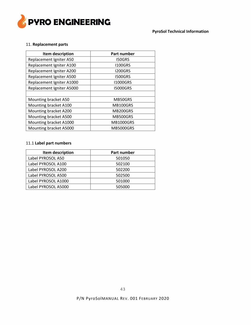
11. Replacement parts
Item description Part number
Replacement Igniter A50 I50GRS
Replacement Igniter A100 I100GRS
Replacement Igniter A200 I200GRS
Replacement Igniter A500 I500GRS
Replacement Igniter A1000 I1000GRS
Replacement Igniter A5000 I5000GRS
Mounting bracket A50 MB50GRS
Mounting bracket A100 MB100GRS
Mounting bracket A200 MB200GRS
Mounting bracket A500 MB500GRS
Mounting bracket A1000 MB1000GRS
Mounting bracket A5000 MB5000GRS
11.1 Label part numbers
Item description Part number
Label PYROSOL A50 501050
Label PYROSOL A100 502100
Label PYROSOL A200 502200
Label PYROSOL A500 502500
Label PYROSOL A1000 501000
Label PYROSOL A5000 505000

45
P/N PyroSolMANUAL REV. 001 FEBRUARY 2020
PyroSol Technical Information

46
P/N PyroSolMANUAL REV. 001 FEBRUARY 2020
PyroSol Technical Information

47
P/N PyroSolMANUAL REV. 001 FEBRUARY 2020
PyroSol Technical Information

48
P/N PyroSolMANUAL REV. 001 FEBRUARY 2020
PyroSol Technical Information

49
P/N PyroSolMANUAL REV. 001 FEBRUARY 2020
PyroSol Technical Information

50
P/N PyroSolMANUAL REV. 001 FEBRUARY 2020
PyroSol Technical Information

51
P/N PyroSolMANUAL REV. 001 FEBRUARY 2020
PyroSol Technical Information

52
P/N PyroSolMANUAL REV. 001 FEBRUARY 2020
PyroSol Technical Information
13. Info sheets PYROSOL generators
13.1 PYROSOL A50 Fixed Aerosol Generator
Installation: The PYROSOL A50 generator can be installed vertically (cover directed upwards) or horizontally. The PYROSOL© A50 Fire Extinguisher is based on the environment friendly SFE Powdered Aerosol
technology, listed on the USEPA Halon Alternatives SNAP list as Powdered Aerosol A.
The A50 model is designed to extinguish and provide extinguishment for Class A (solid fuel),
B (liquid and gas fuel), and C (electrical) fires in defined enclosures.
The extinguishing agent concentration required for each type of fire and volume to be protected is
determined by the solid SFE agent content in the PYROSOL© unit and the number of units per system.
The extinguishing agent delivered by the PYROSOL© system is a powdered aerosol created in-situ by a
chemical reaction taking place in a non-pressurized container, delivering dry powder small particles
(1-5 microns) floating in inert gases.
The PYROSOL© A50 unit produces large amounts of powdered aerosol, designed to extinguish a A-class
fire in a 0.32m3 (320 liters) closed volume as designed by the NFPA 2010 standard.
The system is compatible with standard detection and control systems and can be installed inside or
outside the protected volume.

53
P/N PyroSolMANUAL REV. 001 FEBRUARY 2020
PyroSol Technical Information
FEATURES & BENEFITS
Powdered Aerosol Halon Replacement
No Ozone Depletion (ODP)
No Global Warming (GWP)
Non-toxic
Highly Efficient - 120 gr/m³
Maintenance Free
Small-Safe-Simple. Piping not required.
For Class A-B-C- Total Flooding Applications
Extremely Cost Effective
APPLICATION EXAMPLES
· CNC - machines and Engine compartments
· Computer Control rooms (sub floor; above ceiling)
· Electrical cabinets and Wind Turbine Nacelles
· Generator & compressor rooms and compartments
· Flammable and combustible liquids and gas storage
· Marine applications
· Paint rooms and battery storage
· Telecommunications facilities
· Military
TECHNICAL SPECIFICATIONS
· Extinguishing Volume: 0.32 m³ (156 gr/m³) including 30% safety factor
· Activation Mode: Electrical
· Powdered Aerosol Color: white / light gray
· Discharge Time: 13 seconds
· Temperature Range: -40°C (-40°F) to 54°C (130°F)
· Toxicity: None
· SFE Weight: 50 gr
· SFE Specific Gravity: 1.2 - 1.5 gr/cm³
· SFE Combustion Velocity: 1.1 -1.2 mm/sec.
· Power Supply: 1.35 A
· Ignition: Electrical match (SPEX)
· Electrical Resistance: 0.85 - 1.85 Ohm (~ 0.2)
· Dim: W 50mm (1.96") H 50mm (1.96") L 97mm (3.81")
· Total Weight: 0.6 kg (1.3 lbs.)
· Ozone Depletion Potential: None
. Global Warming Potential: None

54
P/N PyroSolMANUAL REV. 001 FEBRUARY 2020
PyroSol Technical Information
13.2 PYROSOL© A100 Fixed Aerosol Generator
Installation: PYROSOL A100 generator can be installed vertically (cover directed upwards) or horizontally, see picture below.

55
P/N PyroSolMANUAL REV. 001 FEBRUARY 2020
PyroSol Technical Information
The PYROSOL© A100 Fire Extinguisher is based on the environment friendly SFE Powdered Aerosol
technology, listed on the USEPA Halon Alternatives SNAP list as Powdered Aerosol A.
The A100 model is designed to extinguish and provide extinguishment for Class A (solid fuel),
B (liquid and gas fuel), and C (electrical) fires in defined enclosures.
The extinguishing agent concentration required for each type of fire and volume to be protected is
determined by the solid SFE agent content in the PYROSOL© unit and the number of units per system.
The extinguishing agent delivered by the PYROSOL© system is a powdered aerosol created in-situ by a
chemical reaction taking place in a non-pressurized container, delivering dry powder small particles
(1-5 microns) floating in inert gases.
The PYROSOL© A100 unit produces large amounts of powdered aerosol, designed to extinguish a A-class
fire in a 0.64 m3 (640 liters) closed volume as designed by the NFPA 2010 standard.
The system is compatible with standard detection and control systems and can be installed inside or
outside the protected volume.
FEATURES & BENEFITS
· Powdered Aerosol Halon Replacement
· No Ozone Depletion (ODP)
· No Global Warming (GWP)
· Non-toxic
· Highly Efficient - 120 gr/m³
· Maintenance Free
· Small-Safe-Simple. Piping not required.
· For Class A-B-C Total Flooding Applications
· Extremely Cost Effective
APPLICATION EXAMPLES
· CNC - machines and Engine compartments
· Computer Control rooms (sub floor; above ceiling)
· Electrical cabinets and Wind Turbine Nacelles
· Generator & compressor rooms and compartments
· Flammable and combustible liquids and gas storage
· Marine applications
· Paint rooms and battery storage
· Telecommunications facilities
· Military
TECHNICAL SPECIFICATIONS

56
P/N PyroSolMANUAL REV. 001 FEBRUARY 2020
PyroSol Technical Information
· Extinguishing Volume: 0.64 m³ (156 gr/m³)
including 30% safety factor
· Activation Mode: Electrical
· Powdered Aerosol Color: white / light gray
· Discharge Time: 14 seconds
· Temperature Range: -40°C (-40°F) to 54°C (130°F)
· Toxicity: None
· SFE Weight: 100 gr
· SFE Specific Gravity: 1.2 - 1.5 gr/cm³
· SFE Combustion Velocity: 1.1 -1.2 mm/sec.
· Power Supply: 1.35 A
· Ignition: Electrical match (SPEX)
· Electrical Resistance: 0.85 - 1.85 Ohm (± 0.2)
· Dim: W 60mm (2.36") H 60mm (2.36") L 170mm (6.7")
· Total Weight: 1.2 kg / 2.6 lbs.
· Ozone Depletion Potential: None
· Global Warming Potential: None

57
P/N PyroSolMANUAL REV. 001 FEBRUARY 2020
PyroSol Technical Information
13.3 PYROSOL© A200 Fixed Aerosol Generator
Installation: PYROSOL A200 generator can be installed vertically (cover directed upwards) or horizontally, see picture below.

58
P/N PyroSolMANUAL REV. 001 FEBRUARY 2020
PyroSol Technical Information
The PYROSOL© A200 Fire Extinguisher is based
on the environment friendly SFE Powdered Aerosol technology, listed on the USEPA Halon Alternatives
SNAP list as Powdered Aerosol A.
The A50 model is designed to extinguish and provide extinguishment for Class A (solid fuel),
B (liquid and gas fuel), and C (electrical) fires in defined enclosures.
The extinguishing agent concentration required for each type of fire and volume to be protected is
determined by the solid SFE agent content in the PYROSOL© unit and the number of units per system.
The extinguishing agent delivered by the PYROSOL© system is a powdered aerosol created in-situ by a
chemical reaction taking place in a non-pressurized container, delivering dry powder small particles
(1-5 microns) floating in inert gases.
The PYROSOL© A200 unit produces large amounts of powdered aerosol, designed to extinguish a fire in a
1.28 m3 closed volume as designed by the NFPA 2010 standard.
The system is compatible with standard detection and control systems and can be installed inside or
outside the protected volume.
FEATURES & BENEFITS
· Powdered Aerosol Halon Replacement
· No Ozone Depletion (ODP)
· No Global Warming (GWP)
· Non-toxic
· Highly Efficient - 120 gr/m³
· Maintenance Free
· Small-Safe-Simple. Piping not required.
· For Class A-B-C Total Flooding Applications
· Extremely Cost Effective
APPLICATION EXAMPLES
· CNC - machines
· Computer Control rooms (sub floor; above ceiling)
· Electrical cabinets
· Generator & compressor rooms and compartments
· Flammable and combustible liquids and gas storage
· Marine applications
· Paint and battery storage
· Engine compartments
· Telecommunications facilities
· Military
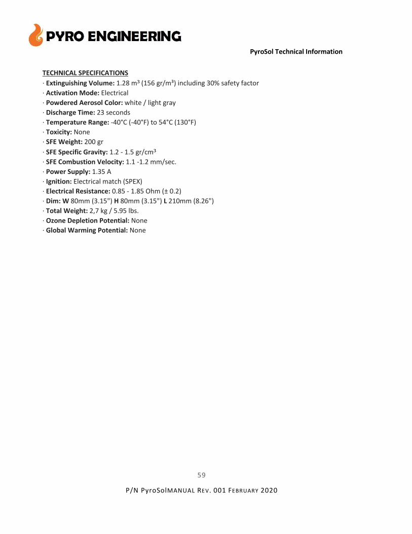
59
P/N PyroSolMANUAL REV. 001 FEBRUARY 2020
PyroSol Technical Information
TECHNICAL SPECIFICATIONS
· Extinguishing Volume: 1.28 m³ (156 gr/m³) including 30% safety factor
· Activation Mode: Electrical
· Powdered Aerosol Color: white / light gray
· Discharge Time: 23 seconds
· Temperature Range: -40°C (-40°F) to 54°C (130°F)
· Toxicity: None
· SFE Weight: 200 gr
· SFE Specific Gravity: 1.2 - 1.5 gr/cm³
· SFE Combustion Velocity: 1.1 -1.2 mm/sec.
· Power Supply: 1.35 A
· Ignition: Electrical match (SPEX)
· Electrical Resistance: 0.85 - 1.85 Ohm (± 0.2)
· Dim: W 80mm (3.15") H 80mm (3.15") L 210mm (8.26")
· Total Weight: 2,7 kg / 5.95 lbs.
· Ozone Depletion Potential: None
· Global Warming Potential: None

60
P/N PyroSolMANUAL REV. 001 FEBRUARY 2020
PyroSol Technical Information
13.4 PYROSOL© A500 Fixed Aerosol Generator
Installation: PYROSOL A500 generator can be installed vertically (cover directed upwards) or horizontally, see picture below.

61
P/N PyroSolMANUAL REV. 001 FEBRUARY 2020
PyroSol Technical Information
The PYROSOL© A500 Fire Extinguisher is based on the environment friendly SFE Powdered Aerosol
technology, listed on the USEPA Halon Alternatives SNAP list as Powdered Aerosol A. The A500 model is
designed to extinguish and provide extinguishment for Class A (solid fuel),
B (liquid and gas fuel), and C (electrical) fires in defined enclosures.
The extinguishing agent concentration required for each type of fire and volume to be protected is
determined by the solid SFE agent content in the PYROSOL© unit and the number of units per system.
The extinguishing agent delivered by the PYROSOL© system is a powdered aerosol created in-situ by a
chemical reaction taking place in a non-pressurized container, delivering dry powder small particles (1-5
microns) floating in inert gases.
The PYROSOL© A500 unit produces large amounts of powdered aerosol, designed to extinguish a fire in a
3.2 m3 closed volume as designed by the NFPA 2010 standard.
The system is compatible with standard detection and control systems and can be installed inside or
outside the protected volume.
FEATURES & BENEFITS
· Powdered Aerosol Halon Replacement
· No Ozone Depletion (ODP)
· No Global Warming (GWP)
· Non-toxic
· Highly Efficient - 100 gr/m³
· Maintenance Free
· Small-Safe-Simple. Piping not required.
· For Class A-B-C Total Flooding Applications
· Extremely Cost Effective
APPLICATION EXAMPLES
· CNC - machines and Engine compartments
· Computer Control rooms (sub floor; above ceiling)
· Electrical cabinets and Wind Turbine Nacelles
· Generator & compressor rooms and compartments
· Flammable and combustible liquids and gas storage
· Marine applications
· Paint rooms and battery storage
· Telecommunications facilities
· Military

62
P/N PyroSolMANUAL REV. 001 FEBRUARY 2020
PyroSol Technical Information
TECHNICAL SPECIFICATIONS
· Extinguishing Volume: 3.2 m³ (156 gr/m³) including 30% safety factor
· Activation Mode: Electrical
· Powdered Aerosol Color: white / light gray
· Discharge Time: 32 seconds
· Temperature Range: -40°C (-40°F) to 54°C (130°F)
· Toxicity: None
· SFE Weight: 500 gr / 17.64oz.
· SFE Specific Gravity: 1.2 - 1.5 gr/cm³
· SFE Combustion Velocity: 1.1 -1.2 mm/sec.
· Power Supply: 1.35 A
· Ignition: Electrical match (SPEX)
· Electrical Resistance: 0.85 - 1.85 Ohm (± 0.2)
· Dim: W 120 mm (4.72") H 120 mm (4.72") L 245 mm (9.64")
· Total Weight: 11.6 kg (25.6 pound)
· Ozone Depletion Potential: None
· Global Warming Potential: None

63
P/N PyroSolMANUAL REV. 001 FEBRUARY 2020
PyroSol Technical Information
13.5 PYROSOL© A1000 Fixed Aerosol Generator
Installation: PYROSOL A1000 generator can be installed vertically (cover directed upwards) or horizontally, see picture below.

64
P/N PyroSolMANUAL REV. 001 FEBRUARY 2020
PyroSol Technical Information
The PYROSOL© A1000 Fire Extinguisher is based on the environment friendly SFE Powdered Aerosol
technology, listed on the USEPA Halon Alternatives SNAP list as Powdered Aerosol A.
The A1000 model is designed to extinguish and provide extinguishment for Class A (solid fuel),
B (liquid and gas fuel), and C (electrical) fires in defined enclosures.
The extinguishing agent concentration required for each type of fire and volume to be protected is
determined by the solid SFE agent content in the PYROSOL© unit and the number of units per system.
The extinguishing agent delivered by the PYROSOL© system is a powdered aerosol created in-situ by a
chemical reaction taking place in a non-pressurized container, delivering dry powder small particles (1-5
microns) floating in inert gases.
The PYROSOL© A1000 unit produces large amounts of powdered aerosol, designed to extinguish a fire in
a 6.41 m3 closed volume as designed by the NFPA 2010 standard.
The system is compatible with standard detection and control systems and can be installed inside or
outside the protected volume.
FEATURES & BENEFITS
· Powdered Aerosol Halon Replacement
· No Ozone Depletion (ODP)
· No Global Warming (GWP)
· Non-toxic
· Highly Efficient - 120 gr/m³
· Maintenance Free
· Small-Safe-Simple. Piping not required.
· For Class A-B-C Total Flooding Applications
· Extremely Cost Effective
APPLICATION EXAMPLES
· CNC - machines and Engine compartments
· Computer Control rooms (sub floor; above ceiling)
· Electrical cabinets and Wind Turbine Nacelles
· Generator & compressor rooms and compartments
· Flammable and combustible liquids and gas storage
· Marine applications
· Paint rooms and battery storage
· Telecommunications facilities
· Military

65
P/N PyroSolMANUAL REV. 001 FEBRUARY 2020
PyroSol Technical Information
TECHNICAL SPECIFICATIONS
· Extinguishing Volume: 6.41 m³ (156 gr/m³) including 30% safety factor
· Activation Mode: Electrical
· Powdered Aerosol Color: white / light gray
· Discharge Time: 46 seconds
· Temperature Range: -40°C (-40°F) to 54°C (130°F)
· Toxicity: None
· SFE Weight: 1000 gr
· SFE Specific Gravity: 1.2 - 1.5 gr/cm³
· SFE Combustion Velocity: 1.1 -1.2 mm/sec.
· Power Supply: 1.35 A
· Ignition: Electrical match (SPEX)
· Electrical Resistance: 0.85 - 1.85 Ohm (± 0.2)
· Dim: W 120mm (4.72") H 120mm (4.72") L 320mm (12.59")
· Total Weight: 12.5 kg / 27.55 lbs.
· Ozone Depletion Potential: None
· Global Warming Potential: None

66
P/N PyroSolMANUAL REV. 001 FEBRUARY 2020
PyroSol Technical Information
13.6 PYROSOL© A5000 Fixed Aerosol Generator
Installation: PYROSOL A5000 generator can be installed vertically (cover directed upwards) or horizontally.
The PYROSOL© A5000 Fire Extinguisher is based on the environment friendly SFE Powdered Aerosol
technology, listed on the USEPA Halon Alternatives SNAP list as Powdered Aerosol A.
The A5000 model is designed to extinguish and provide extinguishment for Class A (solid fuel),
B (liquid and gas fuel), and C (electrical) fires in defined enclosures.
The extinguishing agent concentration required for each type of fire and volume to be protected is
determined by the solid SFE agent content in the PYROSOL© unit and the number of units per system.
The extinguishing agent delivered by the PYROSOL© system is a powdered aerosol created in-situ by a
chemical reaction taking place in a non-pressurized container, delivering dry powder small particles
(1-5 microns) floating in inert gases.
The PYROSOL© A5000 unit produces large amounts of powdered aerosol, designed to extinguish a fire in
a 32 m3 closed volume as designed by the NFPA 2010 standard.
The system is compatible with standard detection and control systems and can be installed inside or
outside the protected volume.

67
P/N PyroSolMANUAL REV. 001 FEBRUARY 2020
PyroSol Technical Information
FEATURES & BENEFITS
· Powdered Aerosol Halon Replacement
· No Ozone Depletion (ODP)
· No Global Warming (GWP)
· Non-toxic
· Highly Efficient - 120 gr/m³
· Maintenance Free
· Small-Safe-Simple. Piping not required.
· For Class A-B-C Total Flooding Applications
· Extremely Cost Effective
APPLICATION EXAMPLES
· CNC - machines and Engine compartments
· Computer Control rooms (sub floor; above ceiling)
· Electrical cabinets and Wind Turbine Nacelles
· Generator & compressor rooms and compartments
· Flammable and combustible liquids and gas storage
· Marine applications
· Paint rooms and battery storage
· Telecommunications facilities
· Military
TECHNICAL SPECIFICATIONS
· Extinguishing Volume: 32 m³ (156 gr/m³) including 30% safety factor
· Activation Mode: Electrical
· Powdered Aerosol Color: white / light gray
· Discharge Time: 58 seconds
· Temperature Range: -40°C (-40°F) to 54°C (130°F)
· Toxicity: None
· SFE Weight: 5000 gr / 11.02lbs.
· SFE Specific Gravity: 1.2 - 1.5 gr/cm³
· SFE Combustion Velocity: 1.1 -1.2 mm/sec.
· Power Supply: 1.35 A
· Ignition: Electrical match (SPEX)
· Electrical Resistance: Linear Connection 1.6 – 2.8 Ohm(± 0.2) / Parallel Connection 0.4 - 1.0 Ohm (± 0.2) · Dim: W 190 mm (7.48") H 445 mm (17.5") L 390 mm (15.34")
· Total Weight: 46 kg (101.41 lbs.)
· Ozone Depletion Potential: None
· Global Warming Potential: None

68
P/N PyroSolMANUAL REV. 001 FEBRUARY 2020
PyroSol Technical Information
14. Fire classes by EN-2
15. Fire Classes by NFPA
69
P/N PyroSolMANUAL REV. 001 FEBRUARY 2020
PyroSol Technical Information
Appendix E – Referenced Publications
UL-2775, April 2014, Fixed Condensed Aerosol Extinguishing System Units
NFPA 2010, Standard for Fixed Aerosol Fire Extinguishing Systems, 2010 Edition for installation.
Inspection, testing and maintenance requirements.
NFPA 70 National Electrical Code®, 2005 Edition
NFPA 72 National Fire Alarm Code®, 2010 Edition
NFPA 2001 Standard on Clean Agent Fire Extinguishing Systems
ANSI C2, National Electrical Safety Code, 2001
ISO /lEC Guide 7, Requirements for Standards Suitable for Use for Conformity Assessment, 1994.
IMO MSC/Circ.1270, Guidelines for the Approval of Fixed Aerosol Fire-Extinguishing Systems
Equivalent to Fixed Gas Fire-Extinguishing Systems, as Referred to in SOLAS 74, for Machinery Spaces;
2008 Edition
Title 29, Code of Federal Regulations, Part 1910, Subpart S. Title 46, Code of Federal Regulations,
Subchapter C, Parts 24-28.
Title 46, Code of Federal Regulations, Subchapter J, "Electrical Engineering."
Title 49, Code of Federal Regulations, Parts 171-190.
Title 49, Code of Federal Regulations, Part 172.101, Subpart B.
Title 49, Code of Federal Regulations, Part 173.34(e) (01). Title 49, Code of Federal Regulations, Parts
178.36 and 178.37.
Other References
NFPA 10, Standard for Portable Fire Extinguishers, 2002 edition.
NFPA 13, Standard for the Installation of Sprinkler Systems, 2002 edition.
NFPA 51B, Standard for Fire Prevention during Welding, Cutting, and Other Hot Work, 2003 edition.
NFPA 101®, Life Safety Code®, 2006 edition.
NFPA 820, Standard for Fire Protection in Wastewater Treatment and Collection Facilities, 2003 edition.

70
P/N PyroSolMANUAL REV. 001 FEBRUARY 2020
PyroSol Technical Information
Appendix F – Definitions
Except where otherwise noted, the following definitions are taken from NFPA 2010, Standard for Fixed
Aerosol Fire-Extinguishing Systems, 2010 Edition.
Actuating mechanism.
A mechanism whose automatic or guide operation leads to the discharge of extinguishing agent.
Agent Quantity.
Mass of solid aerosol-forming compound required to achieve the design application density within the
protected volume within the specified discharge time.
Approved.
Acceptable to the authority having jurisdiction.
Authority Having Jurisdiction (AHJ).
An organization, office, or individual responsible for enforcing the requirements of a code or standard, or
for approving equipment, materials, an installation, or a procedure.
Automatic.
That which provides a function without the necessity of human intervention. [NFPA 101, 2006]
Automatic/guide switch.
Means of converting the system from automatic to guide actuation.
Classification for Fires
Class A Fire.
Fires in ordinary combustible materials, such as wood, cloth, paper, rubber, and many plastics.
[NFPA 10, 2013]
Class B Fire.
Fires in flammable liquids, petroleum greases, tars, oil, oil-based paints, solvents, lacquers, alcohols, and
flammable gases. [NFPA 10, 2013]
Class C Fire.
Fires that involve energized electrical equipment. [NFPA 10, 2013]

71
P/N PyroSolMANUAL REV. 001 FEBRUARY 2020
PyroSol Technical Information
Clearance.
Electrical Clearance.
The unobstructed air distance between extinguishing system equipment, including piping and nozzles,
and unenclosed or un-insulated live electrical components not at ground potential.
Thermal Clearance.
The air distance between a condensed aerosol generator and any structure or components sensitive to
the temperature developed by the generator.
Condensed Aerosol.
An extinguishing medium consisting of finely divided solid particles, generally less than 10 microns in
diameter, and gaseous matter, generated by a combustion process of a solid aerosol-forming compound.
Coolant.
A heat-absorbing medium or process.
Design Application Density (g/m³).
Extinguishing application density, including a safety factor, required for system design purposes.
Discharge Port.
A passage such as nozzles or openings on an aerosol generator where aerosol is released when the
generator is actuated.
Disconnect Switch.
A guide operated switch, electrically supervised and secured from unauthorized use, that prevents the
automatic or guide electrical activation of the aerosol generators during maintenance by electrically
opening the releasing circuit.
Extinguishing Application Density (g/m³).
Minimum mass of a specific aerosol-forming compound per m3 of enclosure volume required to
extinguish fire involving particular fuel under defined experimental conditions excluding any safety
factor.
Generator.
A device for creating a fire-extinguishing medium by pyrotechnical means.
Generator Casing.
72
P/N PyroSolMANUAL REV. 001 FEBRUARY 2020
PyroSol Technical Information
The surface of the generator, excluding the
surface containing the discharge ports.
Guide.
Requiring intentional intervention to accomplish a function.
Hold Time.
Period of time during which an extinguishing agent is required to maintain an even distribution
throughout the protected volume in an amount at least at the extinguishing application density.
Hot work.
Work involving burning, welding, or similar operation that is capable of initiating fire or explosion.
[NFPA 51B, 2003]
Inspection.
A visual examination of a system or portion thereof to verify that it appears to be in operating condition
and free of physical damage. [NFPA 820, 2003]
Listed.
Equipment, materials, or services included in a list published by an organization that is acceptable to the
authority having jurisdiction and concerned with evaluation of products or services, that maintains
periodic inspection of production of listed equipment or materials or periodic evaluation of services, and
whose listing states that either the equipment, material, or service meets appropriate designated
standards or has been tested and found suitable for a specified purpose.
Maintenance.
Work performed to ensure that equipment operates as directed by the manufacturer.
Normally Occupied.
An area or space where, under normal circumstances, persons are present.
Normally Unoccupied.
An area or space not normally occupied by people but that can be entered occasionally for brief periods.
Particulate Density.
The density of solid particulate in g/m3 after discharge of the aerosol system at the design application
density. This information is used to assess the degrees of visibility obscuration and the potential health
effects of accidental exposure to the agent.
Protected Volume.

73
P/N PyroSolMANUAL REV. 001 FEBRUARY 2020
PyroSol Technical Information
Volume enclosed by the building elements
around the protected enclosure, minus the volume of any permanent impermeable building elements
within the enclosure.
Release
The physical discharge or emission of aerosol as a consequence of the condensed aerosol generator's
actuation or operation of the dispersed aerosol agent container.
Shall.
Indicates a mandatory requirement.
Should.
Indicates a recommendation or that which is advised but not required.
Solid Aerosol‐Forming Compound.
A solid mixture of oxidant, combustible component and technical admixtures that produces a condensed
aerosol upon actuation.
Standard.
A document, the main text of which contains only mandatory provisions using the word "shall" to
indicate requirements and which is in a form generally suitable for mandatory reference by another
standard or code or for adoption into law. Non-mandatory provisions shall be located in an appendix or
annex, footnote, or fine-print note and are not to be considered a part of the requirements of a standard.
Supervisory Signal.
A signal indicating the need for action in connection with the supervision of guard tours, the fire
suppression systems or the maintenance features of related systems. [NFPA 72, 2002].
Total Flooding Extinguishing System.
A system arranged to discharge an extinguishing agent into an enclosed space to achieve a uniform
distribution of that extinguishing agent, at or above the design application density, throughout the space.
Unoccupiable.
An area or space which cannot be occupied due to dimensional or other physical constraints.
The following definitions shall be applicable to marine aerosol extinguishing systems:

74
P/N PyroSolMANUAL REV. 001 FEBRUARY 2020
PyroSol Technical Information
A‐60 Class Division.
A bulkhead or deck designed to resist the passage of smoke and flame for 1 hour, including limiting the
temperature rise on the unexposed side to 180° C (325° F).
Heat‐Sensitive Material.
A material whose melting point is below 1700°F (926.7°C). [NFPA 13, 2002]
Marine System.
An aerosol system installed on a merchant vessel, ship, barge, boat, pleasure craft, offshore platform or
other floating structure.
Space.
Cargo Space.
A space for the carriage or storage of items or products that are transported by the vessel.
Machinery Space.
A space protected by an aerosol system containing an internal combustion engine or mechanical
equipment for handling, pumping, or transferring flammable or combustible liquids as a fuel to internal
combustion engine.
Vessel.
Inspected vessel.
A vessel operated on the navigable waterways of the United States that is subject to the regulations in 46
CFR, which require it to be certificated and inspected as a passenger ship, cargo ship, oceanographic ship
or a tank vessel.
Uninspected vessel.
A vessel operated on the navigable waterways of the United States that is subject to the regulations in 46
CFR Subchapter C, Parts 24 - 28, including pleasure craft, tugboats, towing vessels and certain fishing
vessels.


![49113426 Design Installation Maintenance Manual FM200 Fike[2]](https://static.documents.pub/doc/80x56/553264554a795936578b459c/49113426-design-installation-maintenance-manual-fm200-fike2.jpg)


