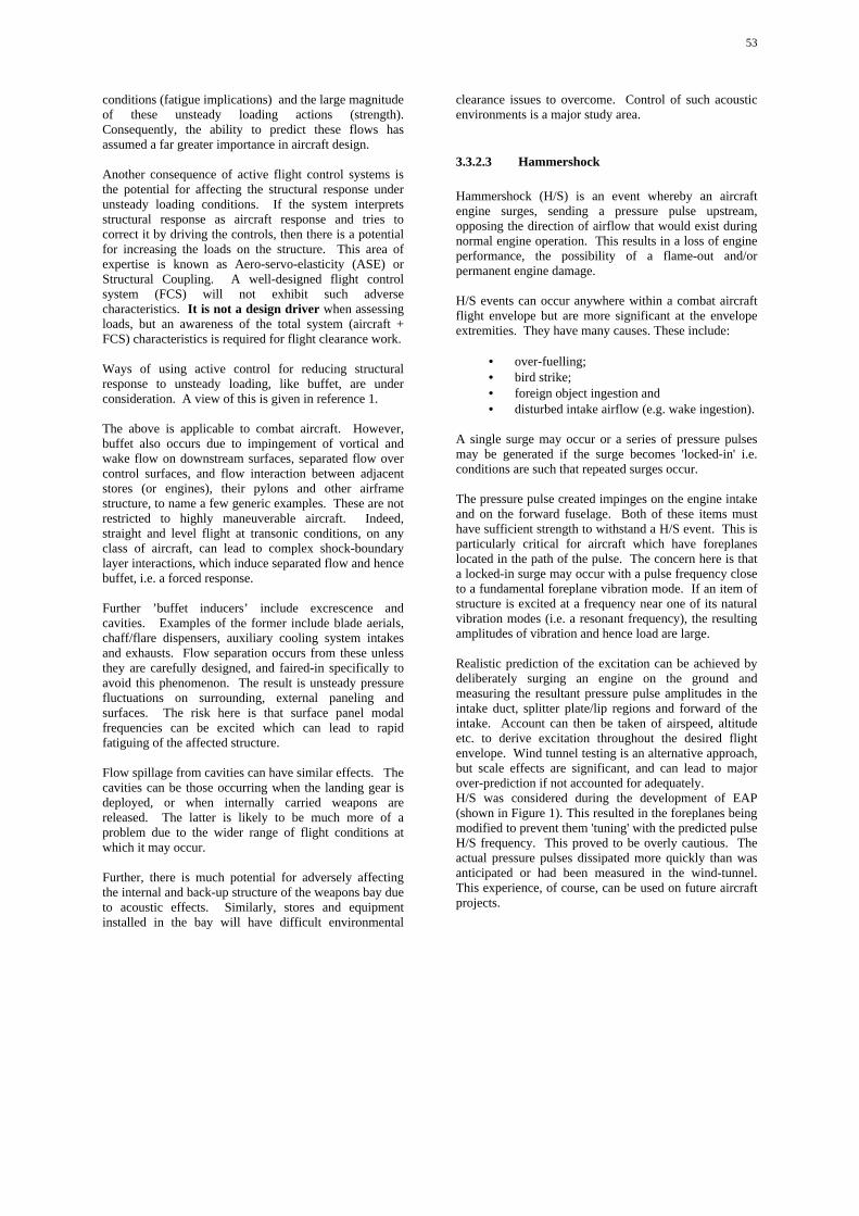
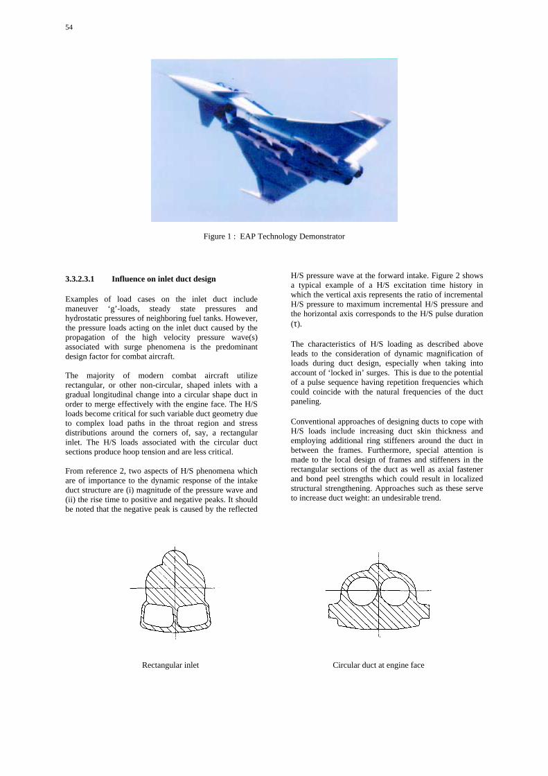
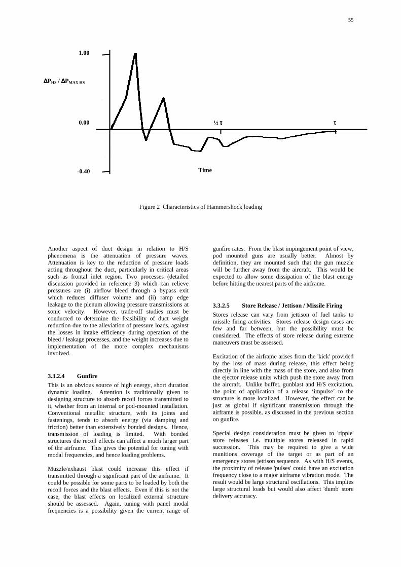
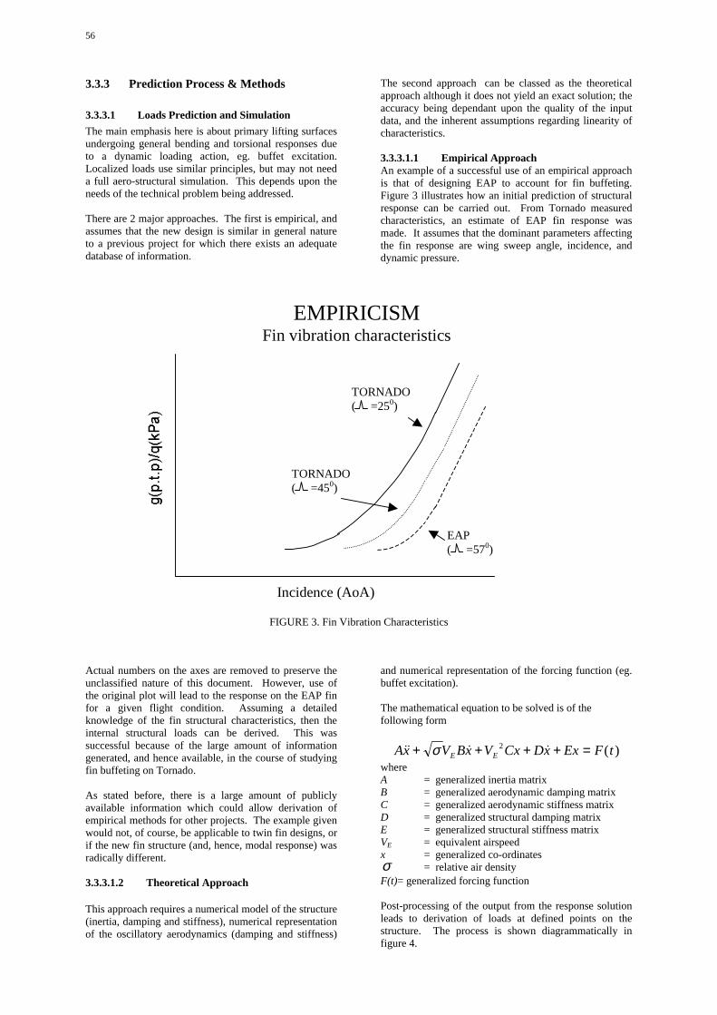
RTO-TR-045 AC/323(AVT-024)TP/30 NORTH ATLANTIC TREATY ORGANISATION RESEARCH AND TECHNOLOGY ORGANISATION BP 25, 7 RUE ANCELLE, F-92201 NEUILLY-SUR-SEINE CEDEX, FRANCE RTO TECHNICAL REPORT 45 Design Loads for Future Aircraft (Les charges de calcul pour de futurs a´ eronefs) Work performed by the RTO Applied Vehicle Technology Panel (AVT) TG 024. Published February 2002 Distribution and Availability on Back Cover RTO-TR-045
Transcript
RTO-TR-045AC/323(AVT-024)TP/30
NORTH ATLANTIC TREATY ORGANISATION
RESEARCH AND TECHNOLOGY ORGANISATION
BP 25, 7 RUE ANCELLE, F-92201 NEUILLY-SUR-SEINE CEDEX, FRANCE
RTO TECHNICAL REPORT 45
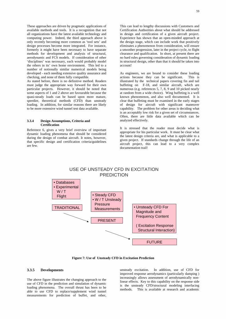
Design Loads for Future Aircraft(Les charges de calcul pour de futurs aeronefs)
Work performed by the RTO Applied Vehicle Technology Panel (AVT) TG 024.
Published February 2002
Distribution and Availability on Back Cover
RT
O-T
R-0
45
REPORT DOCUMENTATION PAGE Form Approved OMB No.0704-0188
Public reporting burder for this collection of information is estibated to average 1 hour per response, including the time for reviewing instructions, searching existing data sources, gathering and maintaining the data needed, and completingand reviewing this collection of information. Send comments regarding this burden estimate or any other aspect of this collection of information, including suggestions for reducing this burder to Department of Defense, WashingtonHeadquarters Services, Directorate for Information Operations and Reports (0704-0188), 1215 Jefferson Davis Highway, Suite 1204, Arlington, VA 22202-4302. Respondents should be aware that notwithstanding any other provision oflaw, no person shall be subject to any penalty for failing to comply with a collection of information if it does not display a currently valid OMB control number. PLEASE DO NOT RETURN YOUR FORM TO THE ABOVE ADDRESS.
1. REPORT DATE (DD-MM-YYYY)01-02-2002
2. REPORT TYPE 3. DATES COVERED (FROM - TO)xx-xx-2002 to xx-xx-2002
4. TITLE AND SUBTITLEDesign Loads for Future AircraftUnclassified
5a. CONTRACT NUMBER5b. GRANT NUMBER5c. PROGRAM ELEMENT NUMBER
6. AUTHOR(S) 5d. PROJECT NUMBER5e. TASK NUMBER5f. WORK UNIT NUMBER
7. PERFORMING ORGANIZATION NAME AND ADDRESSResearch and Technology OrganisationNorth Atlantic Treaty OrganisationBP 25, 7 rue AncelleF-92201 Neuilly-sur-Seine Cedex, Francexxxxx
8. PERFORMING ORGANIZATION REPORTNUMBER
9. SPONSORING/MONITORING AGENCY NAME AND ADDRESSNATO Research and Technology OrganizationBP25, Rue AncelleF-92201 Neuilly-Sur-Seine Cedex, Francexxxxx
12. DISTRIBUTION/AVAILABILITY STATEMENTAPUBLIC RELEASE,13. SUPPLEMENTARY NOTES14. ABSTRACTThis RTO Task Group reviewed the requirements which regular flight and manoeuvring will put as design loads on the structure of futureNATO aircraft, addressing also safety aspects, structural weight, elastic effects and influence of the control system. Treated are: load criticalflight manoeuvres as well as external loads such as induced by turbulence. Existing specifications are reviewed and procedures for establishingdesign loads are presented. Metal and composite structures are treated, and the analysis pertains to main structures as well as criticalsubassemblies. Under operational aspects the monitoring of loads and of structural fatigue are treated and some actual failure cases areanalysed. The request for NATO agreements on relevant design criteria is mentioned.15. SUBJECT TERMSAerodynamic loads Flight manoeuvers Aircraft design; Gust loads Airframes; Load monitoring systems Aviation safety; NATO agreementsComposite structures; Procedures Design loads; RTO Task Group Dynamic loads; Specifications Failure analysis; Structural analysis Fatigue(materials); Structural weight Flight control; Turbulence Flight loads16. SECURITY CLASSIFICATION OF: 17. LIMITATION
19b. TELEPHONE NUMBERInternational Area CodeArea Code Telephone Number703767-9007DSN427-9007
Standard Form 298 (Rev. 8-98)Prescribed by ANSI Std Z39.18
This page has been deliberately left blank
Page intentionnellement blanche
RTO-TR-045AC/323(AVT-024)TP/30
NORTH ATLANTIC TREATY ORGANISATION
RESEARCH AND TECHNOLOGY ORGANISATION
BP 25, 7 RUE ANCELLE, F-92201 NEUILLY-SUR-SEINE CEDEX, FRANCE
RTO TECHNICAL REPORT 45
Design Loads for Future Aircraft(Les charges de calcul pour de futurs aeronefs)
Work performed by the RTO Applied Vehicle Technology Panel (AVT) TG 024.
The Research and TechnologyOrganisation (RTO) of NATO
RTO is the single focus in NATO for Defence Research and Technology activities. Its mission is to conduct and promotecooperative research and information exchange. The objective is to support the development and effective use of nationaldefence research and technology and to meet the military needs of the Alliance, to maintain a technological lead, and toprovide advice to NATO and national decision makers. The RTO performs its mission with the support of an extensivenetwork of national experts. It also ensures effective coordination with other NATO bodies involved in R&T activities.
RTO reports both to the Military Committee of NATO and to the Conference of National Armament Directors. It comprises aResearch and Technology Board (RTB) as the highest level of national representation and the Research and TechnologyAgency (RTA), a dedicated staff with its headquarters in Neuilly, near Paris, France. In order to facilitate contacts with themilitary users and other NATO activities, a small part of the RTA staff is located in NATO Headquarters in Brussels. TheBrussels staff also coordinates RTO’s cooperation with nations in Middle and Eastern Europe, to which RTO attachesparticular importance especially as working together in the field of research is one of the more promising areas of initialcooperation.
The total spectrum of R&T activities is covered by the following 7 bodies:
• AVT Applied Vehicle Technology Panel
• HFM Human Factors and Medicine Panel
• IST Information Systems Technology Panel
• NMSG NATO Modelling and Simulation Group
• SAS Studies, Analysis and Simulation Panel
• SCI Systems Concepts and Integration Panel
• SET Sensors and Electronics Technology Panel
These bodies are made up of national representatives as well as generally recognised ‘world class’ scientists. They alsoprovide a communication link to military users and other NATO bodies. RTO’s scientific and technological work is carriedout by Technical Teams, created for specific activities and with a specific duration. Such Technical Teams can organiseworkshops, symposia, field trials, lecture series and training courses. An important function of these Technical Teams is toensure the continuity of the expert networks.
RTO builds upon earlier cooperation in defence research and technology as set-up under the Advisory Group for AerospaceResearch and Development (AGARD) and the Defence Research Group (DRG). AGARD and the DRG share common rootsin that they were both established at the initiative of Dr Theodore von Karman, a leading aerospace scientist, who early onrecognised the importance of scientific support for the Allied Armed Forces. RTO is capitalising on these common roots inorder to provide the Alliance and the NATO nations with a strong scientific and technological basis that will guarantee asolid base for the future.
The content of this publication has been reproduceddirectly from material supplied by RTO or the authors.
Published February 2002
Copyright RTO/NATO 2002All Rights Reserved
ISBN 92-837-1077-0
Printed by St. Joseph Ottawa/Hull(A St. Joseph Corporation Company)
Design Loads for Future Aircraft(RTO TR-045 / AVT-024)
Executive Summary
The selection of design loads and requirements is defining the structural weight of airplanes and theirsafety. Therefore the definition of requirements should be performed very critically by the customerand structural weight should be assessed based on sensitivity analysis of the total aircraft whichincludes flight manoeuvre simulation, flight control system, aerodynamics and elastic effectsintroduced by finite elements. To produce these analyses is the job of the aircraft companies.
After selection of most load critical flight manoeuvres (pull up manoeuvres, initiation of rollmanoeuvres etc.) the calculation of airloads and inertia loads must include the flight control system andits failure cases because it affects the motion of the control surfaces and therefore the aircraft.
With the advent of carbon fibre composite structures discrete loads are the predominant limiting designconditions but it should be emphasised that most structures are of a hybrid nature with metal framewhich are still susceptible to fatigue loads. For airplanes designed to civil requirements such astransport airplanes, tankers etc. the definition of continuous turbulence and inclusion of FCS failurecases and nonlinearities such as control surface angles is extremely important.
There was a long way from load assumptions used by the Wright Brothers who designed their Flyer toa 5g limit to the load limiting capabilities of the care free handling flight control system of theEurofighter. Also the US-Airforce Mil-Specifications which were used to design NATO airplanes suchas Tornado, F16 and F18 in the 1970’s are obsolete today and the MIL-A-87221 (USAF) is only aframe without the essential quantitative material. All these issues are addressed in this manualincluding comparisons of regulations and descriptions of new specifications. Complete procedures howto establish design loads are presented which should help for the design of new airplanes.
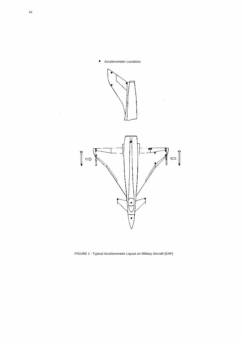
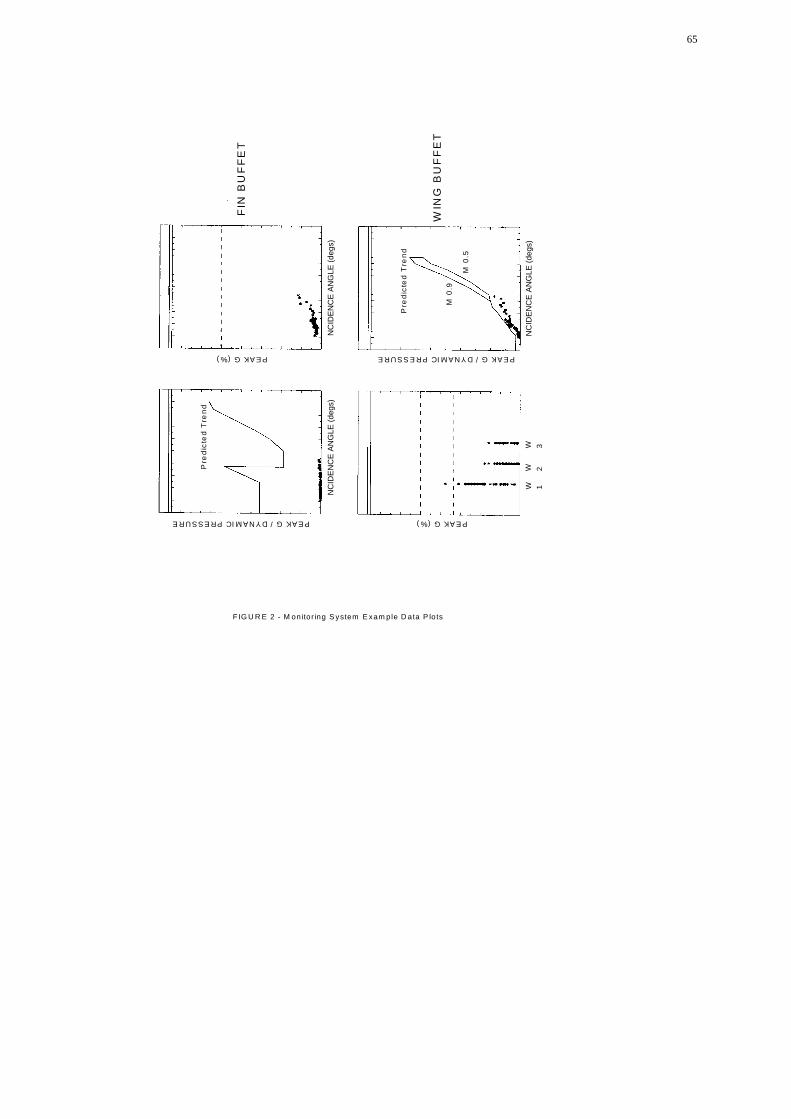
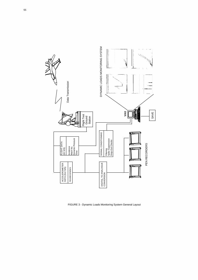
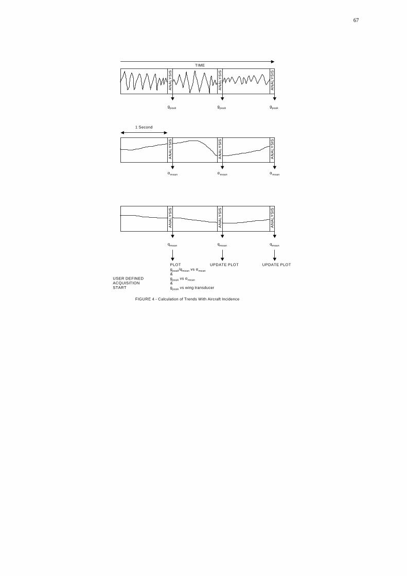
The importance of dynamic phenomena which produce design loads for various aircraft parts such asintakes, leading edges etc. is also highlighted. Loads monitoring systems are necessary to provecalculated loads and monitor fatigue loads to establish the remaining structural life. There is adescription of a modern system.
For transport type aircraft gust load cases are the most critical for strength design and they are also themain fatigue loading source for the major part of the structure. Methods for discrete and continuousgust loading cases are presented together with nonlinear example calculations.
In the appendix there is a description of failure cases and their effect on loads for transport aircraft anda specification of a landing gear which could be used as an example how to specify the whole structureas a system. The military use of this manual is to establish procedures to build the lightest structure forthe military requirements. Agreement on requirements and design loads within the NATO countriescould standardise pilot training, aircraft usage, increase aircraft life and reduce maintenance. Since thesearch of the best usage of the aircraft for its military purpose will continue to integrate structure andavionics such as fire and flight control systems as an example there will be a continuous need forfuture work.
iii
Les charges de calcul pour de futurs aeronefs(RTO TR-045 / AVT-024)
Synthese
Le choix des charges theoriques et des specifications determine la masse structurale des aeronefs et leursecurite. C’est pourquoi la definition des specifications doit etre realisee de facon tres rigoureuse par leclient, la masse structurale etant, dans ce cas, evaluee a partir d’une etude de sensibilite de l’aeronef dansson ensemble, couvrant une simulation d’evolution en vol, un systeme de commandes de vol, desconsiderations aerodynamiques et d’eventuels effets elastiques introduits par des elements finis. Il incombeaux avionneurs d’effectuer ces etudes.
Apres avoir defini les evolutions en vol les plus critiques en termes de charges (ressource, tonneau, etc.), lecalcul des charges aerodynamiques et des charges d’inertie doit egalement inclure le systeme de commandede vol et ses defaillances potentielles car il a une incidence sur le mouvement des gouvernes et parconsequent sur l’aeronef.
Avec l’avenement des structures composites en fibre de carbone, les charges discretes sont devenues lesprincipales conditions restrictives pour la conception, mais il est a noter que la plupart des structures sonthybrides avec une cellule metallique et restent vulnerables aux charges de fatigue. En ce qui concerne lesaeronefs concus selon des specifications civiles, tels que les avions de transport, les avions ravitailleurs,etc., la definition de la turbulence continue et l’inclusion des cas de pannes du systeme de commandes devol (FCS) et des non-linearites, tels que les angles de gouverne, sont extremement importantes.
Un long chemin separe les hypotheses de charge retenues par les freres Wright, qui ont concu leur “Flyer”pour un facteur de charge limite de 5g, et les caracteristiques de limite de charge du systeme de commandesde vol a pilotage securise de l’Eurofighter. De meme, les specifications MIL de l’US-Airforce, utiliseesdans les annees 70 pour la conception des avions de combat de l’OTAN, tels que le Tornado, le F16 et leF18, sont aujourd’hui obsoletes et la specification MIL-A-87221 (USAF) ne represente qu’un cadre, denuedu materiau quantitatif essentiel. L’ensemble de ces questions est aborde dans le present manuel avec lacomparaison des reglements et des descriptions de nouvelles specifications. Des procedures completespermettant de definir des charges de calcul sont presentees, ce qui devrait faciliter la conception desnouveaux aeronefs.
L’importance des phenomenes dynamiques, qui generent des charges de calcul s’appliquant a differentselements de l’aeronef, tels que les entrees d’air, les bords d’attaque etc. est egalement soulignee. Dessystemes de surveillance des charges sont necessaires pour justifier les charges calculees et surveiller lescharges de fatigue en vue d’etablir la duree de vie structurale restante. La description d’un systeme moderneest donnee.
Pour les aeronefs de transport, les charges de rafale sont l’element le plus critique en ce qui concerne lescalculs de resistance, et elles sont egalement la principale source de charges de fatigue pour la majeurepartie de la structure. Les methodes relatives aux cas de charges de rafale continues et discontinues sontpresentees avec des calculs d’exemple non lineaires.
L’annexe presente une description des cas de panne et de leurs effets sur les charges pour les avions detransport, ainsi que la specification d’un train d’atterrissage qui pourrait etre utilisee comme exemple pouretablir la specification de l’ensemble de la structure en tant que systeme. Ce manuel permet de mettre aupoint des procedures pour la fabrication de structures les plus legeres repondant aux specificationsmilitaires. Un accord portant sur les specifications et les charges de calcul en vigueur dans les pays del’OTAN pourrait conduire a la standardisation de la formation des pilotes et de l’exploitation des aeronefs,associee a l’accroissement de la duree de vie des aeronefs et a l’allegement de la maintenance. Enconclusion, etant donne que la recherche de l’exploitation optimale d’un aeronef a des fins militairescontinuera d’integrer la structure et l’avionique, tel que par exemple les systemes de commandes de vol etde tir, la demande de travaux de recherche sera maintenue.
iv
Contents
Page
Executive Summary iii
Synthese iv
Publications of the RTO Applied Vehicle Technology Panel ix
Task Group Members xi
1 Introduction 1
2 Loads Requirements Review 1
2.1 The development of maneuver load criteria for agile aircraft 12.1.1 Introduction 12.1.2 Status of present Criteria 12.1.3 The influence of piloting technique 62.1.4 The influence of advanced control systems 72.1.5 Conclusion 82.1.6 References 9
3.2 Non Classical Approach 213.2.1 Maximum Load Concept 213.2.2 Operational Flight Parameter Approach 263.2.3 Determination and Verification of Operational Maneuver Parameters and Time 27
4.2 Overview of Gust Requirements 724.2.1 Draft NPRM on Continuous Turbulence 72
4.3 Comparison of Methods to calculated Continuous Turbulence Design Loads for 72Non-Linear Aircraft4.3.1 Analyses made by NLR 734.3.2 Analyses made by the University of Manchester 74
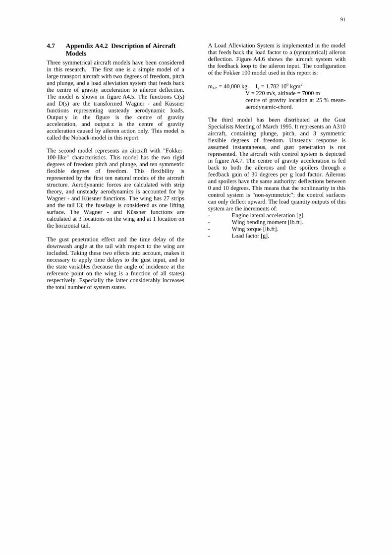
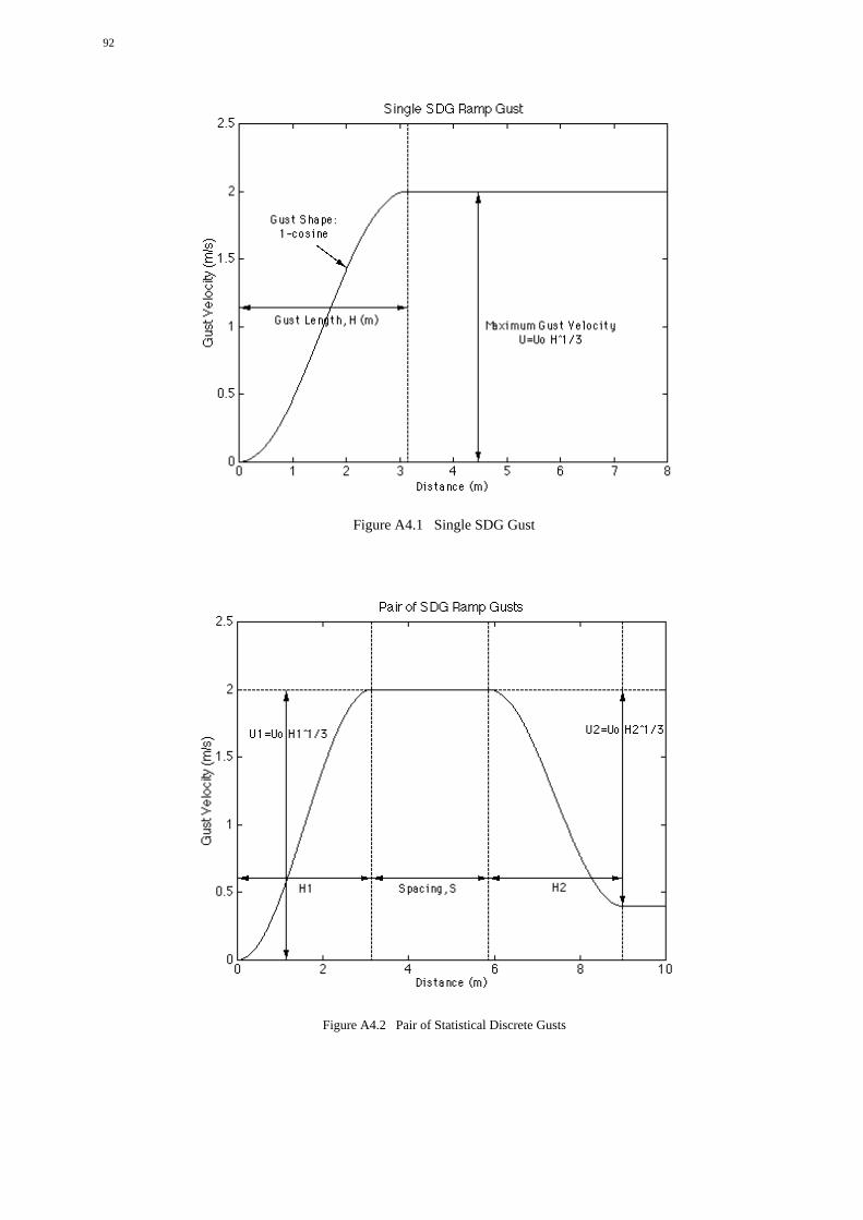
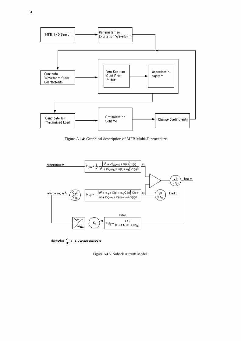
4.7 Appendix A4.2 Description of Aircraft Models 91
5 A More Global Approach 96
5.1 Why a more global approach 96
5.2 Limit Loads 965.2.1 Basic principles of the “more global approach” for limit loads 965.2.2 “Maximum Loads” through “Load Severity Indicators” 965.2.3 “Maximum Loads Expected in Service” 975.2.4 Application to design of “fly by wire” aircraft 97
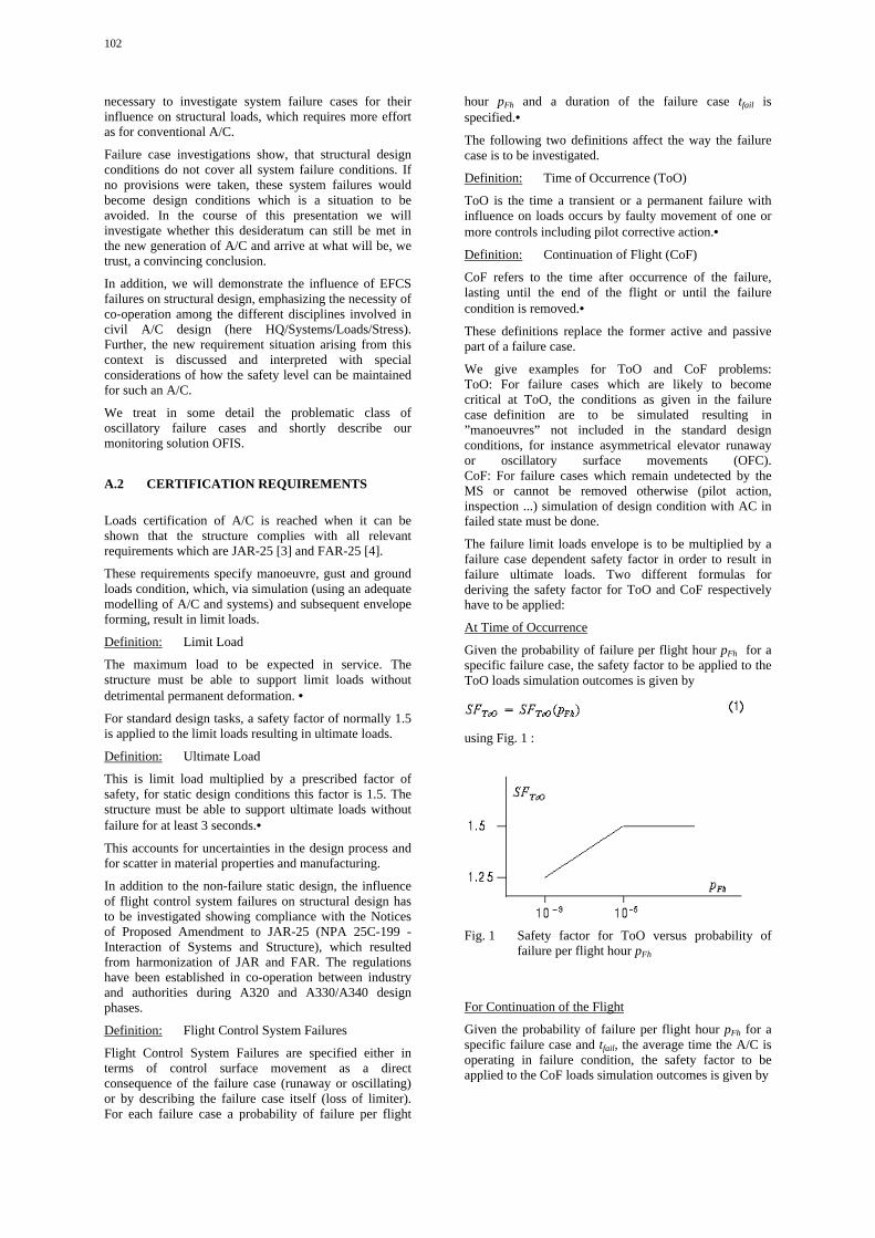
5.3 Ultimate load definition and Safety Factors for multiphysical effects 97
5.4 Safety factors evolution with innovations 985.4.1 The particular case of fly by wire aircraft 985.4.2 Towards probabilistic approaches 98
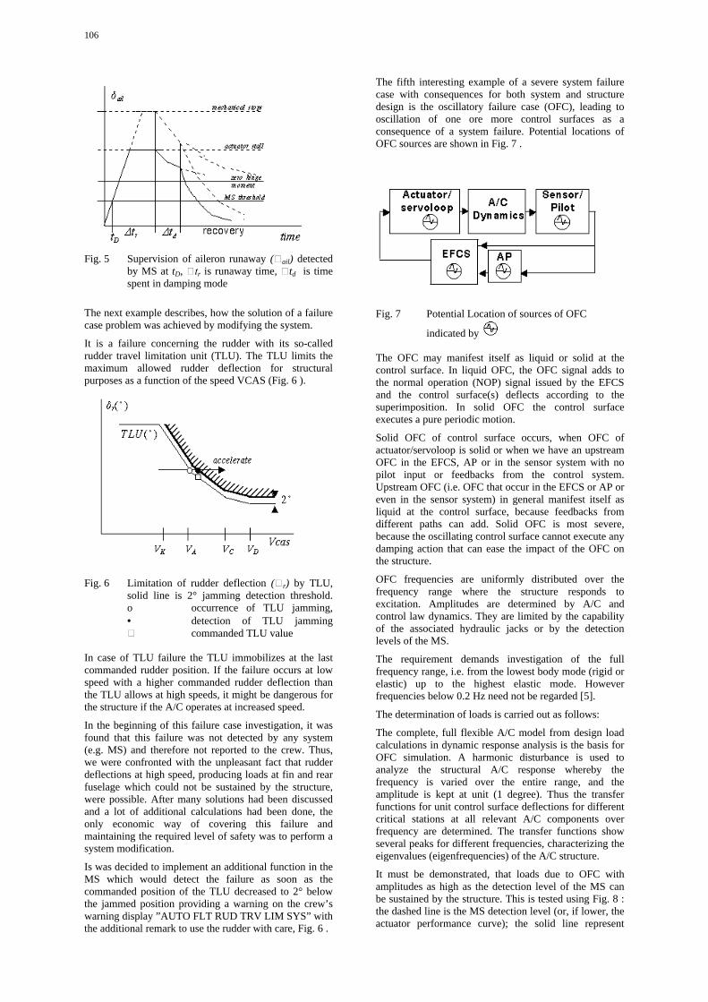
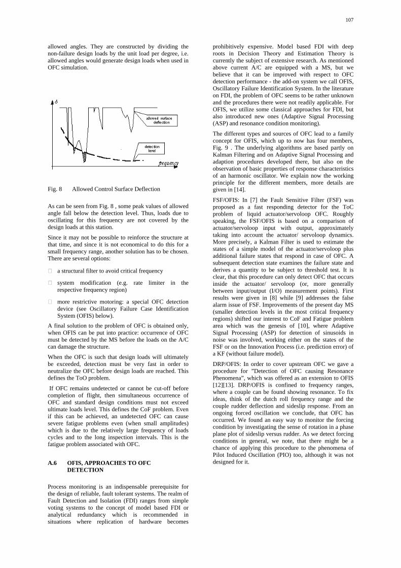
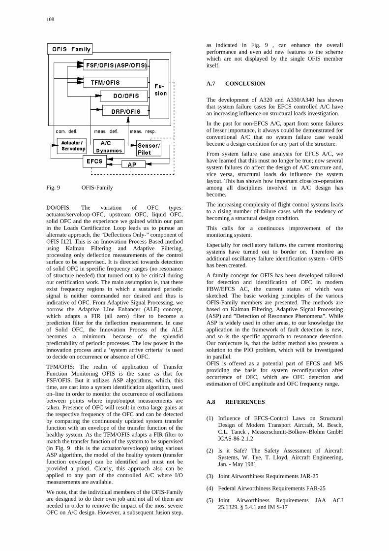
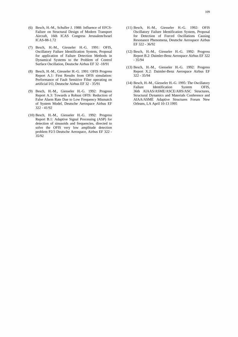
Appendix A The Impact of Electronic Flight Control System (EFCS) Failure Cases onStructural Design Loads 99
A.1 Introduction 101
A.2 Certification Requirements 102
A.3 EFCS Failures 103
A.4 Procedure to Handle Failure Cases in Loads 104
A.5 Consequences on Design 105
A.6 OFIS, Approaches to OFC Detection 107
A.7 Conclusion 108
A.8 References 108
Appendix B The NATO Aircraft Landing Gear Design Specification 111
B.1 Introduction 113
B.2 Scope 113
B.3 Application 113B.3.1 Program 113B.3.2 Aircraft 113B.3.3 Landing Gear Structure 114B.3.4 Use 114B.3.5 Structure 114B.3.6 Instructional Handbook 114B.3.7 Deviations 114
B.4 Applicable Documents 114
vi
B.5 Requirements 114B.5.1 Detailed Structural Design Requirements 114B.5.2 General Parameters 117B.5.3 Specific Design and Construction Parameters 160B.5.4 Structural Loading Conditions 177B.5.5 Vibration 188B.5.6 Strength 189B.5.7 Durability 194B.5.8 Damage Tolerance 200B.5.9 Durability and Damage Tolerance Control 206B.5.10 Sensitivity Analysis 208B.5.11 Force Management 208B.5.12 Production Facilities, Capabilities, and Processes 211B.5.13 Engineering Data Requirements 211
B.6 Verification 212B.6.1 Detailed Structural Design Requirements 212B.6.2 General Parameters 214B.6.3 Specific Design and Construction Parameters 224B.6.4 Structural Loading Conditions 226B.6.5 Vibration 232B.6.6 Strength 236
B.7 Definitions 265B.7.1 Acoustic Environment 265B.7.2 Aerial Delivery 265B.7.3 Aeroacoustic Fatigue 265B.7.4 Aeroacoustic Load 265B.7.5 Aircraft 265B.7.6 Airframe 265B.7.7 Air Transport 265B.7.8 Air Vehicle 265B.7.9 Auxiliary Systems 265B.7.10 Container Delivery System (CDS) 265B.7.11 Damage Tolerance 265B.7.12 Damping Coefficient (G) 265B.7.13 Degree of Inspectability 265B.7.14 Discipline 266B.7.15 Divergence 266B.7.16 Durability 266B.7.17 Durability Service Life 266B.7.18 Factor Of Uncertainty 266B.7.19 Fail-Safe Crack Arrest Structure 266B.7.20 Critical Parts 266B.7.21 Frequency of Inspection 267B.7.22 Hardness 267B.7.23 Initial Quality 267B.7.24 Load Factor 267B.7.25 Margin of Safety 267B.7.26 Minimum Assumed Initial Damage Size 267B.7.27 Minimum Assumed In-Service Damage Size 267B.7.28 Minimum Period of Unrepaired Service Usage 267B.7.29 Multiple Load Path — Fail-Safe Structure 267B.7.30 Operational Needs 267B.7.31 Pallet 267B.7.32 Personnel Ear Protection 267B.7.33 Pure Tone or Narrow Band 267B.7.34 Reported Sound Pressure Level 267B.7.35 Safety of Flight Structure 268B.7.36 Slow Crack Growth Structure 268
vii
B.7.37 Sound Pressure Levels 268B.7.38 Special Mission Aircraft 268B.7.39 Speeds 268B.7.40 Store 268B.7.41 Structure 268B.7.42 Structural Integrity 268B.7.43 Structural Operating Mechanisms 268B.7.44 Survivability 268B.7.45 Vulnerability 268B.7.46 Key Process Characteristics 268B.7.47 Key Product Characteristics 269B.7.48 Key Production Process 269B.7.49 Process Capability Index (Cp) 269B.7.50 Production 269B.7.51 Production Control 269B.7.52 Production Process 269B.7.53 A-Basis Allowable 269B.7.54 B-Basis Allowable 269
viii
Publications of the RTOApplied Vehicle Technology Panel
MEETING PROCEEDINGS (MP)
Unmanned Vehicles (UV) for Aerial, Ground and Naval Military OperationsMP-052, January 2002
Active Control Technology for Enhanced Performance Operational Capabilities of Military Aircraft,Land Vehicles and Sea VehiclesMP-051, June 2001
Design for Low Cost Operation and SupportMP-37, September 2000
Gas Turbine Operation and Technology for Land, Sea and Air Propulsion and Power Systems (Unclassified)MP-34, September 2000
Aerodynamic Design and Optimization of Flight Vehicles in a Concurrent Multi-Disciplinary EnvironmentMP-35, June 2000
Structural Aspects of Flexible Aircraft ControlMP-36, May 2000
New Metallic Materials for the Structure of Aging AircraftMP-25, April 2000
Small Rocket Motors and Gas Generators for Land, Sea and Air Launched Weapons SystemsMP-23, April 2000
Application of Damage Tolerance Principles for Improved Airworthiness of RotorcraftMP-24, January 2000
Gas Turbine Engine Combustion, Emissions and Alternative FuelsMP-14, June 1999
Fatigue in the Presence of CorrosionMP-18, March 1999
Qualification of Life Extension Schemes for Engine ComponentsMP-17, March 1999
Fluid Dynamics Problems of Vehicles Operation Near or in the Air-Sea InterfaceMP-15, February 1999
Design Principles and Methods for Aircraft Gas Turbine EnginesMP-8, February 1999
Airframe Inspection Reliability under Field/Depot ConditionsMP-10, November 1998
Intelligent Processing of High Performance MaterialsMP-9, November 1998
Exploitation of Structural Loads/Health Data for Reduced Cycle CostsMP-7, November 1998
Missile AerodynamicsMP-5, November 1998
ix
EDUCATIONAL NOTES (EN)
Supercavitating FlowsEN-010, January 2002
Aging Aircraft Fleets: Structural and Other Subsystem AspectsEN-015, March 2001
Aging Engines, Avionics, Subsystems and HelicoptersEN-14, October 2000
Measurement Techniques for High Enthalpy and Plasma FlowsEN-8, April 2000
Development and Operation of UAVs for Military and Civil ApplicationsEN-9, April 2000
Planar Optical Measurements Methods for Gas Turbine Engine LifeEN-6, September 1999
High Order Methods for Computational Physics, Published jointly with Springer-Verlag, GermanyEN-5, March 1999
Fluid Dynamics Research on Supersonic AircraftEN-4, November 1998
Integrated Multidisciplinary Design of High Pressure Multistage Compressor SystemsEN-1, September 1998
TECHNICAL REPORTS (TR)
Ice Accretion Simulation Evaluation TestTR-038, November 2001
NATO East-West Workshop on Magnetic Materials for Power ApplicationsTR-031, August 2001
Verification and Validation Data for Computational Unsteady AerodynamicsTR-26, October 2000
Recommended Practices for Monitoring Gas Turbine Engine Life ConsumptionTR-28, April 2000
A Feasibility Study of Collaborative Multi-facility Windtunnel Testing for CFD ValidationTR-27, December 1999
x
Task Group Members
ChairmanMr. Claude PerronBombardier Inc. CanadaMilitary Aircraft Division10,000 Cargo Road A-4, Montreal International AirportMirabel, Quebec J7N 1H3em: [email protected]
Co-ChairmanProf. Dr. O. SensburgEuropean Aeronautic Defence and Space Company - EADSMilitary Aircraft MT2Postfach 80 11 60, 81663 Munich, Germanyem: [email protected]
BELGIUM Mr. Horst StruckProf. Dr. J. Vantomme Wangeroogerstrasse, 13Royal Military Academy (RMA) D-27755 DelmenhorstDepartment of Civil Engineering em: [email protected] de la renaissance, 30B-1000 Brussels THE NETHERLANDSem: [email protected] Ir. J.B. De Jonge
National Aerospace Lab.CANADA P.O. Box 153Mr. William Glaser 8300 Ad EmmeloordDe havilland Inc., 123 Garratt Blvd em: [email protected], Ontario M3K 1Y5
UNITED KINGDOMFRANCE Mr. R. ChapmanMr. C. Petiau Aerodynamics DepartmentAviation Marcel Dassault British Aerospace, Military Aircraft Div. Warton78, quai Marcel Dassault Aerodrome, Preston, LancsCedex 300
Mr. J. E. Cooper92552 St. Cloud CedexSchool of Engineeringem: [email protected] of ManchesterOxford Road
GERMANY Manchester, M13 9PLMr. K. Fuellhas em: [email protected] Aeronautic Defence and Space
Company - EADSUNITED STATESPostfach 80 11 60Mr. D. Gibson81663 MunichWeapons System Design Centerem: [email protected] Branch, Lockheed Martin
Mr. W. Luber Tactical Aircraft SystemsEuropean Aeronautic Defence and Space P.O. Box 748, Fort Worth
Mr. W. Krabacher81663 Munich, GermanyAFRL/VACM, Building 31em: [email protected] Fifth Street
Mr. M. Spieck Wright Patterson AFBDLR - Institute of Aeroelasticity OH 45433-7202Vehicle Systems Division em: [email protected] Strasse 2082230 Wesslingem: [email protected]
xi
EDITORS
Prof. Dr. O. SensburgEuropean Aeronautic Defence and Space Company - EADS
During the past few years there has been an increasedinterest of the aircraft community on design loads foraircraft. Consequently there was a workshop in 1996SC73 on “Loads and Requirements for Military Aircraft”(AGARD Report 815). Elastic effects on design loadswere presented at a Workshop: “Static AeroelasticEffects on High Performance Aircraft.”
Also an Agadogragh was written on Gust Loads:AGARDograph 317: “Manual on the Flight of FlexibleAircraft in Turbulence.” All these topics are covered inthis manual.
With the increased use of active control systems onaircraft, there is currently a strong need to revisit someconcepts used for conventional aircraft and to identify thecorrection to be brought forward to existing procedures tocompute the several loads affecting a military aircraft andthe effect of the active control system. Special attentionhas been given to cover these items.
This report contains the following:
Maneuver Loads
Under this topic, design loads derivation covers thefollowing aspects:
• Aerodynamic/inertia loads• Aeroservoelastic effects• Effects of control system failure on design envelope• Dynamic loads
Gust loads
Although not a major concern for fighter aircraft, gustloads play an important role on aircraft that are designedunder civil requirements. A complete description of themethods used is presented along with recommendationson their use. The effect of control system failure isdescribed for the case of gust alleviation systems inAppendix A.
Aircraft/Landing Gear Loads
The specification of a landing gear as a system is shownin the Appendix B.
Limit Loads Concept
Limit load concepts and design loads criteria are exploredfor actively controlled aircraft.
CONCLUSIONS
In this manual several approaches are presented how tocalculate design loads for existing and future aircraft.There is a description of requirements included withsome historical background.
It very soon becomes clear that for fly by wire, agile,inherently unstable aircraft, these requirements as far asmanoeuvres are concerned are obsolete.
Therefore, an approach as described for the Eurofighter,where flight parameters are restricted and care freehandling of the aircraft is provided, is a possible solution.
Gust loads are also presented with some very interestingcomparisons of methods dealing with non-linear aircraft.
There is also an extensive compendium of dynamic loadswhich may be designing the aircraft structure.
A more global approach is also shown which tries toavoid insufficiencies of classical load regulations.
It is hoped that this manual can be helpful for aircraftdesigners to produce realistic flight loads which willresult in optimum weight structures.
2 Loads Requirements Review
The design of modern fighter aircraft is becoming anincreasingly complex process, and the establishment ofdesign criteria is an extremely important element in thatprocess. The Structures and Materials Panel of AGARDhave noted with concern that the existing designmaneuver load regulations in the NATO nations a ) arenot uniform in content and b) do not generally reflect theactual service experience of the aircraft.
Therefore an AGARD manual was prepared which triesto put together the latest requirement and methods whichhave been used for the design of recent modern airplanes.As an introduction to the present situations twocontributions to military requirements are given. The firstone gives a suggestion how maneuver loads criteria couldbe developed for modern agile aircraft.
In the second one the changes in the USAF StructuralLoad Requirements are presented which show theevolution of general load criteria valid for every aircraftto a specific document which is part of the overallspecification.
Similarly a specification for undercarriage is shown inthe Appendix B. The third set of specifications is for civilairplanes and is laid down in JAR25 (not included in thisreport).
2
2.1 The development of maneuver loadcriteria for agile aircraft
Max HacklingerMunich, FRG
AGARD Report 746, May 1987
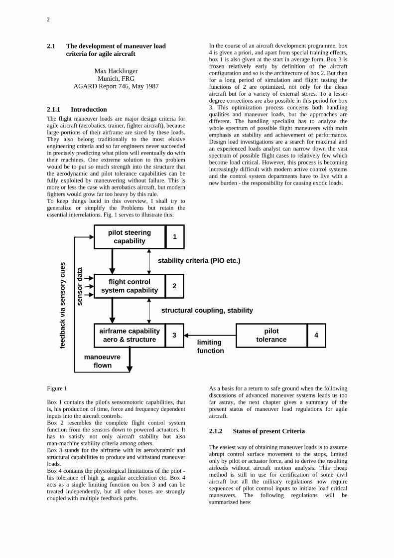
2.1.1 IntroductionThe flight maneuver loads are major design criteria foragile aircraft (aerobatics, trainer, fighter aircraft), becauselarge portions of their airframe are sized by these loads.They also belong traditionally to the most elusiveengineering criteria and so far engineers never succeededin precisely predicting what pilots will eventually do withtheir machines. One extreme solution to this problemwould be to put so much strength into the structure thatthe aerodynamic and pilot tolerance capabilities can befully exploited by maneuvering without failure. This ismore or less the case with aerobatics aircraft, but modernfighters would grow far too heavy by this rule.To keep things lucid in this overview, I shall try togeneralize or simplify the Problems but retain theessential interrelations. Fig. 1 serves to illustrate this:
Figure 1
Box 1 contains the pilot's sensomotoric capabilities, thatis, his production of time, force and frequency dependentinputs into the aircraft controls.Box 2 resembles the complete flight control systemfunction from the sensors down to powered actuators. Ithas to satisfy not only aircraft stability but alsoman-machine stability criteria among others.Box 3 stands for the airframe with its aerodynamic andstructural capabilities to produce and withstand maneuverloads.Box 4 contains the physiological limitations of the pilot -his tolerance of high g, angular acceleration etc. Box 4acts as a single limiting function on box 3 and can betreated independently, but all other boxes are stronglycoupled with multiple feedback paths.
In the course of an aircraft development programme, box4 is given a priori, and apart from special training effects,box 1 is also given at the start in average form. Box 3 isfrozen relatively early by definition of the aircraftconfiguration and so is the architecture of box 2. But thenfor a long period of simulation and flight testing thefunctions of 2 are optimized, not only for the cleanaircraft but for a variety of external stores. To a lesserdegree corrections are also possible in this period for box3. This optimization process concerns both handlingqualities and maneuver loads, but the approaches aredifferent. The handling specialist has to analyze thewhole spectrum of possible flight maneuvers with mainemphasis an stability and achievement of performance.Design load investigations are a search for maximal andan experienced loads analyst can narrow down the vastspectrum of possible flight cases to relatively few whichbecome load critical. However, this process is becomingincreasingly difficult with modern active control systemsand the control system departments have to live with anew burden - the responsibility for causing exotic loads.
As a basis for a return to safe ground when the followingdiscussions of advanced maneuver systems leads us toofar astray, the next chapter gives a summary of thepresent status of maneuver load regulations for agileaircraft.
2.1.2 Status of present Criteria
The easiest way of obtaining maneuver loads is to assumeabrupt control surface movement to the stops, limitedonly by pilot or actuator force, and to derive the resultingairloads without aircraft motion analysis. This cheapmethod is still in use for certification of some civilaircraft but all the military regulations now requiresequences of pilot control inputs to initiate load criticalmaneuvers. The following regulations will besummarized here:
pilot steeringcapability
flight controlsystem capability
airframe capabilityaero & structure
pilottolerance
2
3 4
1
stability criteria (PIO etc.)
structural coupling, stability
limitingfunction
manoeuvre flown
sen
sor
dat
a
feed
bac
k vi
a se
nso
ry c
ues
3
• MIL-A-008861 A (USAF) 1971 for the US AirForce
• MIL-A-8861 B (AS) 1986 for the US Navy
• DEF-STAN 00-970 1983 for the UK
• AIR 2004 E 1979 for France.
The US situation at the moment is curious. (A) used to bethe main US specification for flight loads over manyyears. It has been replaced for the Air Force in 1985 byMIL-A-87221 (USAF), but this new specification is onlya frame without the essential quantitative material and assuch no great help for the designer. The US Navy on theother hand, who traditionally used to have their own anddifferent specification, have now adopted the old USAFSpec. (A) and updated and amplified it for application tomodern control system technology, including direct forcecontrol, thrust vectoring etc. Thus (B) seems to be themost up-to-date specification available now. Althoughmodern fighter tactics use combined control inputs inseveral axes, for a starting basis we prefer to treat themseparately as pitching, rolling and yawing maneuvers.
2.1.2.1 Pitching manoeurves
US Air Force
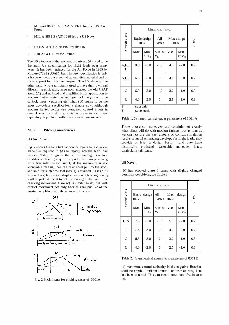
Fig. 2 shows the longitudinal control inputs for a checkedmaneuver required in (A) to rapidly achieve high loadfactors. Table 1 gives the corresponding boundaryconditions. Case (a) requires to pull maximum positive gby a triangular control input; if the maximum is notachievable by this, then the pilot shall pull to the stopsand hold for such time that max. g is attained. Case (b) issimilar to (a) but control displacement and holding time t3
shall be just sufficient to achieve max. g at the end of thechecking movement. Case (c) is similar to (b) but withcontrol movement not only back to zero but 1/2 of thepositive amplitude into the negative direction.
Fig. 2 Stick Inputs for pitching cases of 8861A
Limit load factor
Basic designmass
Allmasses
Max designmass
Air
craf
t cla
ss
Max Minat VH
Min atVL
Max Minat VH
t 1 [
sec]
A,F,T1)
8.0 -3.0 -1.0 4.0 -2.0 0.2
A,F,T2)
6.5 -3.0 -1.0 4.0 -2.0 0.2
O 6.0 -3.0 -1.0 3.0 -1.0 0.3
U 4.0 -2.0 0 2.5 -1.0 0.3
1) subsonic2) supersonic
Table 1: Symmetrical maneuver parameters of 8861 A
These theoretical maneuvers are certainly not exactlywhat pilots will do with modern fighters, but as long aswe can not use the vast amount of combat simulationresults as an all embracing envelope for flight loads, theyprovide at least a design basis – and they havehistorically produced reasonable maneuver loads,particularly tail loads.
US Navy:
(B) has adopted these 3 cases with slightly changedboundary conditions, see Table 2,
Limit load factor
Basic designmass
Allmasses
Max designmass
Air
craf
t cla
ss
Max Minat VH
Min atVL
Max Minat VH
t 1 [
sec]
F, A 7.5 -3.0 -1.0 5.5 -2.0 0.2
T 7.5 -3.0 -1.0 4.0 -2.0 0.2
O 6.5 -3.0 0 3.0 -1.0 0.3
U 4.0 -2.0 0 2.5 -1.0 0.3
Table 2: Symmetrical maneuver parameters of 8861 B
(d) maximum control authority in the negative directionshall be applied until maximum stabilizer or wing loadhas been attained. This can mean more than –δ/2 in case(c).
4
(e) is a special case for “computer control”, fly -by-wire,active control, stability augmentation, the direct liftcontrol, or other types of control system where the pilotcontrol inputs do not directly its establish control surfaceposition" which we shall call here generically ACTsystems. This case requires that aircraft strength shallalso be sufficient to cover modifications of cases (a) to(c) caused by ACT systems partially failed (transients,changed gains etc.), a requirement which is easier statedthan proven.
UK
In the UK, pitching maneuvers have traditionally beencovered by airplane response calculations after theCzaykowski method which assumed an exponentialfunction for elevator movement and no checking. Thiswas an expedient way to obtain tail loads but the new UKspecification (C) advises that pilot control inputs shouldbe used now. It does not specify any details of these.
France
The French specification (D) is very similar to case (a) of(A), with two differences: it has other load factors, seeTable 3, and it allows a slower stick return to neutral intime t2; for servo controls t1 = t2 shall be derived frommaximum control surface rate under zero load. It doesnot require checking into the negative region as (A) and(B). (see Fig. 3)
Limit load factorAircraftclass
Max min
T1
[sec]
T2
[sec]
III n1* -0.4 n1 0.2 0.3
II 4.0 -1.6 0.2 0.3
I 2.5 -1.0 0.3 0.3
Table3: Symmetrical maneuver parameters of AIR 2004E* n1 defined in the aircraft specification
Fig. 3 Control Inputs of AIR 2004 E
2.1.2.2 Rolling maneuvers (with pitching)
US Air Force
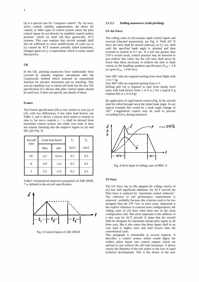
The rolling cases of (A) assume rapid control inputs andreversal (checked maneuvers), see Fig. 4. With 267 Nforce the stick shall be moved sideways in 0.1 sec, helduntil the specified bank angle is attained and thenreverted to neutral in 0.1 sec. If a roll rate greater than270°/s would result, control position may be lessened tojust achieve this value, but the roll rates shall never belower than those necessary to achieve the time to bankcriteria in the handling qualities specification (T360 = 2.8sec gives Pmax ≈150°/sec).
Fast 180° rolls are required starting from level flight with-1 to + 1g.Fast 360° rolls are required starting from n=1.Rolling pull out is required to start from steady levelturns with load factors from 1 to 8 n1 ( for a typical 8 gairplane this is 1 to 6.4 g).
By application of rapid lateral control (Fig. 4) the aircraftshall be rolled through twice the initial bank angle. In ourtypical example this would be a bank angle change of162°. Longitudinal control may be used to preventexceeding 0.8 n1 during maneuver.
Fig. 4 Stick Input of rolling cases of 8861 A
US Navy
The US Navy has in (B) adopted the rolling criteria of(A) but with significant additions: for ACT aircraft thePilot force is replaced by "maximum control authority".The reference to roll performance requirements isremoved - probably because this criterion used to be lessstringent than the 270 °/sec in most cases. Important isthe explicit reference to external store configurations; therolling cases of (A) have often been met in the cleanconfiguration only. But most important is the addition ofa new case for ACT aircraft. It states that the aircraftshall be designed for maximum abrupt pilot inputs in allthree axes. But it also states that these inputs shall in nocase lead to higher rates and load factors than theconventional cases.This paragraph is remarkable in several respects. Itdescribes a control system which would digest thewildest pilots Inputs into control outputs which aretailored to just achieve the old load maximum. It showsclearly the dilemma of the rule maker in the face of rapidtechnical development. This is the dream of the now
5
much advertised carefree (foolproof) handling system, Inreality control systems are primarily optimized for actualmaneuver performance and not for achievement of sometheoretical load cases. On the positive side this criterionrecognizes the need to retain some reference to provenmaneuver design load practice.Another addition in (B) is the requirement that thestructure shall also be designed to withstand thedemonstration requirements of MIL-D-87088 (AS),which apparently is not obvious.
UK
In the UK a wider envelope of initial conditions isrequired for the rolling cases, including a negative g rollreversal: -1.5 to 7.2 g. For the maximum roll rate severallimits are given: at least 1 1/3 of the roll performance
criteria in the handling specification which amounts toabout 200 °/sec; 200 °/sec for ground attack and 250°/sec for aerial combat maneuvers. The control input timehistory is roughly as in (A).
France
The French specification also requires negative initialconditions for the rolling cases: -1.6 to 6.4 g. (D) has control inputs similar to (A), butwith t1 = 0.2 and t3 = 0.3 or maximum servo capability.The roll limits are more severe, i.e., a full 360° roll andpmax ���������� ���������������������� ������� !���� �
that US pilots tend to avoid negative g maneuvers incontrast to their European colleagues:Table 4 summarizes the rolling parameters for a typical8 g airplane.
( A ) ( B ) ( C ) ( D )
MIL-A-8861 A MIL-A-8861-B DEF STAN 970 AIR 2004 E
180° roll –1 to +1 g360° roll at 1grolling pull outfrom 1 to 6.4 g,t1 = t2 = 0.1 sec,pmax = 270°/sec
Same as A plus ACS foolproof ness with maximumcontrol authority plusdemonstrationrequirements
Rolling pull out from –1.5 to 7.2 g,pmax = 1.33 p handling��������
Ground attack 200°/secAerial combat 250°/secNo t1, but maximum servocapability
360 ° roll, pmax = 360°/secrolling pull out from –1.6to 6.4 gt1 = 0.2 sect2 = 0.3 secor max servo capabilityunder zero load andt1 = t2
Table 4: Comparison of rolling parameters (8g airplane)
2.1.2.3 Yawing Maneuvers
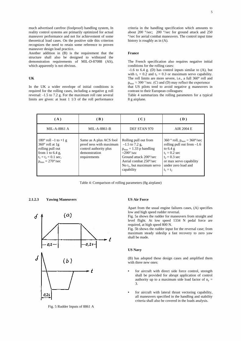
Fig. 5 Rudder Inputs of 8861 A
US Air Force
Apart from the usual engine failures cases, (A) specifieslow and high speed rudder reversal.Fig. 5a shows the rudder for maneuvers from straight andlevel flight. At low speed 1334 N pedal force arerequired, at high speed 800 N.Fig. 5b shows the rudder input for the reversal case; frommaximum steady sideslip a fast recovery to zero yawshall be made.
US Navy
(B) has adopted these design cases and amplified themwith three new ones:
• for aircraft with direct side force control, strengthshall be provided for abrupt application of controlauthority up to a maximum side load factor of ny =3.
• for aircraft with lateral thrust vectoring capability,all maneuvers specified in the handling and stabilitycriteria shall also be covered in the loads analysis.
6
• it is general practice that evasive maneuvers such asjinking, missile break etc. shall be considered in theloads analysis.
UK
(C) requires a rudder kick with 667 N pedal force ormaximum output of the control system at all speeds. Italso requires the traditional British fishtail maneuver:starting from straight level flight, the rudder is movedsinusoidal for 1 1/2 periods of the Dutch Roll frequencywith an amplitude corresponding to 445 N pedal force or2/3 of the actuator maximum.
France
(D) has a rudder reversal case very similar to Fig. 5 b anda rudder kick without reversal, but both slightly slowerthan (A) due to t1 = 0,3 sec.Spinning is somewhat marginal for our theme of pilotcontrolled maneuvers but it deserves mentioning that itcan cause rather high loads. (B) has now increased theyawing velocity of agile aircraft with fuselage mountedengines from the 200 °/sec in (A) to 286 °/sec. This is asevere requirement for long fuselages.
The following figures show typical load maneuversresulting from application of the current US Mil-Specs. toan aircraft with moderate amount of ACT (Tornado).
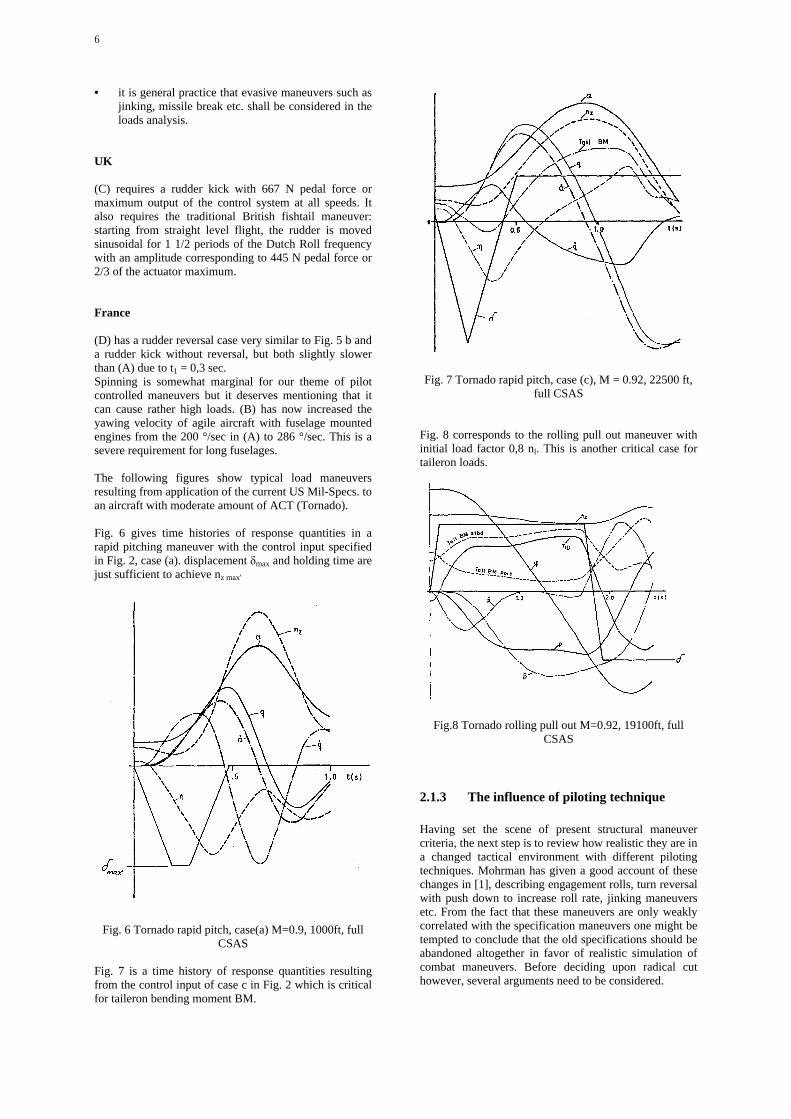
Fig. 6 gives time histories of response quantities in arapid pitching maneuver with the control input specifiedin Fig. 2, case (a). displacement �max and holding time arejust sufficient to achieve nz max'
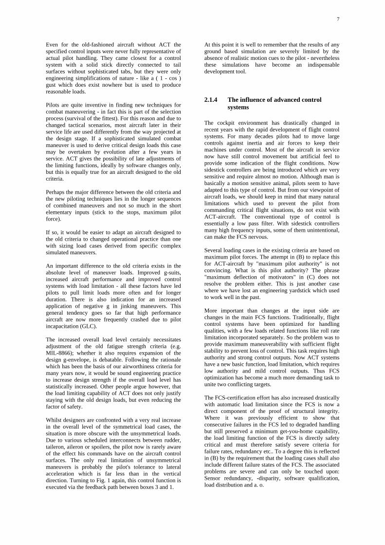
Fig. 7 is a time history of response quantities resultingfrom the control input of case c in Fig. 2 which is criticalfor taileron bending moment BM.
Fig. 7 Tornado rapid pitch, case (c), M = 0.92, 22500 ft,full CSAS
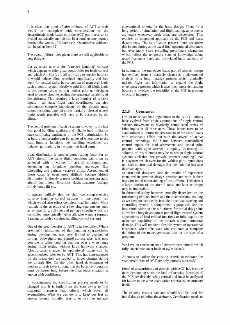
Fig. 8 corresponds to the rolling pull out maneuver withinitial load factor 0,8 nl. This is another critical case fortaileron loads.
Fig.8 Tornado rolling pull out M=0.92, 19100ft, fullCSAS
2.1.3 The influence of piloting technique
Having set the scene of present structural maneuvercriteria, the next step is to review how realistic they are ina changed tactical environment with different pilotingtechniques. Mohrman has given a good account of thesechanges in [1], describing engagement rolls, turn reversalwith push down to increase roll rate, jinking maneuversetc. From the fact that these maneuvers are only weaklycorrelated with the specification maneuvers one might betempted to conclude that the old specifications should beabandoned altogether in favor of realistic simulation ofcombat maneuvers. Before deciding upon radical cuthowever, several arguments need to be considered.
7
Even for the old-fashioned aircraft without ACT thespecified control inputs were never fully representative ofactual pilot handling. They came closest for a controlsystem with a solid stick directly connected to tailsurfaces without sophisticated tabs, but they were onlyengineering simplifications of nature - like a ( 1 - cos )gust which does exist nowhere but is used to producereasonable loads.
Pilots are quite inventive in finding new techniques forcombat maneuvering - in fact this is part of the selectionprocess (survival of the fittest). For this reason and due tochanged tactical scenarios, most aircraft later in theirservice life are used differently from the way projected atthe design stage. If a sophisticated simulated combatmaneuver is used to derive critical design loads this casemay be overtaken by evolution after a few years inservice. ACT gives the possibility of late adjustments ofthe limiting functions, ideally by software changes only,but this is equally true for an aircraft designed to the oldcriteria.
Perhaps the major difference between the old criteria andthe new piloting techniques lies in the longer sequencesof combined maneuvers and not so much in the shortelementary inputs (stick to the stops, maximum pilotforce).
If so, it would be easier to adapt an aircraft designed tothe old criteria to changed operational practice than onewith sizing load cases derived from specific complexsimulated maneuvers.
An important difference to the old criteria exists in theabsolute level of maneuver loads. Improved g-suits,increased aircraft performance and improved controlsystems with load limitation - all these factors have ledpilots to pull limit loads more often and for longerduration. There is also indication for an increasedapplication of negative g in jinking maneuvers. Thisgeneral tendency goes so far that high performanceaircraft are now more frequently crashed due to pilotincapacitation (GLC).
The increased overall load level certainly necessitatesadjustment of the old fatigue strength criteria (e.g.MIL-8866); whether it also requires expansion of thedesign g-envelope, is debatable. Following the rationalewhich has been the basis of our airworthiness criteria formany years now, it would be sound engineering practiceto increase design strength if the overall load level hasstatistically increased. Other people argue however, thatthe load limiting capability of ACT does not only justifystaying with the old design loads, but even reducing thefactor of safety.
Whilst designers are confronted with a very real increasein the overall level of the symmetrical load cases, thesituation is more obscure with the unsymmetrical loads.Due to various scheduled interconnects between rudder,taileron, aileron or spoilers, the pilot now is rarely awareof the effect his commands have on the aircraft controlsurfaces. The only real limitation of unsymmetricalmaneuvers is probably the pilot's tolerance to lateralacceleration which is far less than in the verticaldirection. Turning to Fig. 1 again, this control function isexecuted via the feedback path between boxes 3 and 1.
At this point it is well to remember that the results of anyground based simulation are severely limited by theabsence of realistic motion cues to the pilot - neverthelessthese simulations have become an indispensabledevelopment tool.
2.1.4 The influence of advanced controlsystems
The cockpit environment has drastically changed inrecent years with the rapid development of flight controlsystems. For many decades pilots had to move largecontrols against inertia and air forces to keep theirmachines under control. Most of the aircraft in servicenow have still control movement but artificial feel toprovide some indication of the flight conditions. Nowsidestick controllers are being introduced which are verysensitive and require almost no motion. Although man isbasically a motion sensitive animal, pilots seem to haveadapted to this type of control. But from our viewpoint ofaircraft loads, we should keep in mind that many naturallimitations which used to prevent the pilot fromcommanding critical flight situations, do not exist withACT-aircraft. The conventional type of control isessentially a low pass filter. With sidestick controllersmany high frequency inputs, some of them unintentional,can make the FCS nervous.
Several loading cases in the existing criteria are based onmaximum pilot forces. The attempt in (B) to replace thisfor ACT-aircraft by "maximum pilot authority" is notconvincing. What is this pilot authority? The phrase"maximum deflection of motivators" in (C) does notresolve the problem either. This is just another casewhere we have lost an engineering yardstick which usedto work well in the past.
More important than changes at the input side arechanges in the main FCS functions. Traditionally, flightcontrol systems have been optimized for handlingqualities, with a few loads related functions like roll ratelimitation incorporated separately. So the problem was toprovide maximum maneuverability with sufficient flightstability to prevent loss of control. This task requires highauthority and strong control outputs. Now ACT systemshave a new basic function, load limitation, which requireslow authority and mild control outputs. Thus FCSoptimization has become a much more demanding task tounite two conflicting targets.
The FCS-certification effort has also increased drasticallywith automatic load limitation since the FCS is now adirect component of the proof of structural integrity.Where it was previously efficient to show thatconsecutive failures in the FCS led to degraded handlingbut still preserved a minimum get-you-home capability,the load limiting function of the FCS is directly safetycritical and must therefore satisfy severe criteria forfailure rates, redundancy etc.. To a degree this is reflectedin (B) by the requirement that the loading cases shall alsoinclude different failure states of the FCS. The associatedproblems are severe and can only be touched upon:Sensor redundancy, -disparity, software qualification,load distribution and a. o.
8
It is clear that proof of airworthiness of ACT aircraftwould be incomplete with consideration of thedeterministic loads cases only the ACT part needs to betreated statistically and this can be a cumbersome journeythrough the woods of failure trees. Quantitative guidancecan be taken from [2]
The overall failure rates given there are still applicable tonew designs.
Let us return now to the "carefree handling" conceptwhich appears to offer great possibilities for loads controland which Air Staffs are all too ready to specify becauseit would reduce pilots workload significantly and freethem for tactical tasks. In our context of maneuver loadssuch a control system ideally would limit all flight loadsto the design values so that neither pilot nor designerneed to worry about exceeding the structural capability ofthe airframe. This requires a large number of reliableinputs - air data, flight path coordinates, but alsocontinuous compete knowledge of the aircraft massstatus, including external stores partially released (speedlimits would probably still have to be observed by thepilot).
The central problem of such a system however, is the factthat good handling qualities and reliable load limitationhave conflicting tendencies in the FCS optimization. Soat best, a compromise can be achieved where due to theload limiting functions the handling envelopes arereduced, particularly in the upper left hand corner.
Load distribution is another complicating factor for anACT aircraft the same flight condition can often beachieved with a variety of aircraft configurations,depending an foreplane position, maneuver flapscheduling and perhaps vectored thrust. Assessment ofthose cases is even more difficult because airloaddistribution is already a great problem on modern agileaircraft due to non - linearities, elastic structure, fuselagelift, dynamic lift etc.
It appears unlikely that we shall see comprehensivecarefree handling control systems in operational usewhich would also effect complete load limitation. Morerealistic is the selection of a few single parameters suchas symmetric g, roll rate and perhaps sideslip which arecontrolled automatically. After all, who wants a formula1 racing car with a carefree handling control system?
One of the great benefits of ACT is its flexibility. Wherepreviously adjustment of the handling characteristicsduring development was very limited to changes ofsprings, bobweights and control surface tabs, it is nowpossible to tailor handling qualities over a wide rangeduring flight testing without large hardware changes.Also greater changes in operational usage can beaccommodated later on by ACT. This has consequencesfor the loads; they are subject to larger changes duringthe aircraft life. On the other hand development ofmodern aircraft takes so long that the basic configurationmust be frozen long before the final loads situation isknown with confidence.
In consequence, the certification process needs to bechanged too. It is futile from the start trying to findstructural maneuver load criteria which cover alleventualities. What we can do is to keep our feet anproven ground initially, that is to use the updated
conventional criteria for the basic design. Then, for along period of simulation and flight testing, adjustmentsare made whenever weak areas are discovered. Thisrequires an integrated approach by the FCS and loadsdepartments. The certification process must recognizethis by not aiming at the usual final operational clearance,but over many years providing preliminary clearanceswhich reflect the temporary state of knowledge abouttested maneuver loads and the related build standard ofthe FCS.
In summary, the maneuver loads part of aircraft designhas evolved from a relatively clean-cut, predeterminedanalysis to a long iterative process which graduallyutilizes flight test information to expand the flightenvelopes; a process which is also much more demandingbecause it involves the reliability of the FCS in provingstructural integrity.
2.1.5 ConclusionDesign maneuver load regulations in the NATO nationshave evolved from crude assumptions of single controlsurface movement to relatively complicated series ofPilot inputs in all three axes. These inputs need to bestandardized to permit the assessment of structural loadswith reasonable effort, but with the advent of activecontrol technology the hiatus between standardizedcontrol inputs for load assessment and actual pilotpractice with agile aircraft is rapidly increasing. Asolution of this dilemma may be to design flight controlsystems such that they provide "carefree handling", thatis a system which even for the wildest pilot inputs doesnot lead to structural damage. But this solution has alsodisadvantages:a) structural designers lose the wealth of experiencecontained in previous design practice and with it theirbasis for initial dimensioning of the airframe. This affectsa large portion of the aircraft mass and later re-designmay be impossible.b) Structural safety becomes crucially dependent an thefunctioning of black boxes and their connections. As longas we have no technically feasible direct load sensing andcontrolling system, a compromise is proposed: Use thebest combination of the old criteria for initial design butallow for a long development period flight control systemadjustments of load critical functions to fully exploit themaneuver capability of the aircraft without structuraldamage. This will require a flexible system of operationalclearances where the user can not have a completedefinition of the maneuver capabilities at the start of aprogram.
We have no consistent set of airworthiness criteria whichfully covers maneuver loads of agile aircraft.
Attempts to update the existing criteria to embrace thevast possibilities of ACT are only partially successful.
Proof of airworthiness of aircraft with ACT has becomemore demanding since the load influencing functions ofthe FCS are directly safety critical and must be analyzedfor failure to the same quantitative criteria as the structureitself.
The existing criteria can and should still be used forinitial design to define the airframe. Certification needs to
9
become adaptive to reflect a long period of testing andFCS changes .
2.1.6 References:
( A ) MIL-A-008861 A (USAF) 31.03.1971Airplane Strength and Rigidity, Flight Loads
( B ) MIL-A-8861 D (AS) 07.02.1986Airplane Strength and Rigidity, Flight Loads
( C ) DEF STAN 00-970 October 1985Design and Airworthiness Requirements forService Aircraft, Volume 1 Airplanes,Part 2 Structural Strength and Design for Flight
[ 2 ] Hacklinger , M.:Airworthiness Criteria for Operational ActiveControl Systems.Paper for DGLR panel Aeroelastics andStructural Dynamics 1979 (translation)
2.2 Changes in USAF Structural LoadsRequirements
Daniel Sheets and Robert GeramiLoads and Dynamic Branch
Aeronautical System DivisionASD/ENFL, Wright Patterson Air force Base OH, 45433-
6503, USAAGARD Report 746 , May 1987
The new General Specification for Aircraft Structures,MIL-A-87221 (USAF), does not establish the traditional,fixed requirements, but instead it presents the currenttailored approach to establishing structural loadsrequirements. In most cases the previous specificationsset arbitrary load levels and conditions to be used inaircraft design. These requirements were based uponhistorical experience, without consideration of futurepotential needs or capabilities brought about bytechnology advances. Instead, the new philosophyrequires that loading conditions be established rationallyfor each weapon system based on anticipated usage.Also, compliance with each condition must be verified byanalysis, model test, or full scale measurement.
2.2.1 Introduction
During the late 1970s, several conditions came togetherthat caused the US Air Force to develop new aircraftstructural specifications. While the USAF has always hada policy of reviewing, revising, and upgrading existingspecifications, there were factors favoring a new
approach. The contracting and legal authorities believedthat the existing system of many layers of specificationsneeded to be simplified. Also, rapidly advancingstructural technologies, coupled with new realms ofperformance and control capabilities, demanded that thestructural specifications address much wider range ofconditions while using an ever widening mix oftechnologies. The new military specification for aircraftstructures, MIL-A-87221 (USAF), is a major deviationfrom past requirement practices. It establishes weaponsystem uniquely tailored structural performance andverification requirements for airframes based on anin-depth consideration of operational needs andanticipated usage. In the past, specifications set arbitraryconditions, levels, and values to be used in the design ofbroad categories of aircraft.
Various sources have alleged that design requirementshave not kept pace with current usage practices;especially in the area of flight combat maneuvers. Theseallegations ignore the new requirement philosophy andare wrong for several reasons. The specification,MIL-A-87221 (USAF), does not preclude theconsideration of any type of loading situation. The newspecification actually requires the consideration of anyloading condition that can be identified for eitheranalysis, model testing, or full scale measurement.Therefore, if a loading condition is overlooked, the faultis not with MIL-A-87221 since it is not a set of rigid,pre-determined requirements.
Thus, this new approach does place a greater reliance onthe designer's insight and ability to correctly anticipatethe actual service loads. The term designer represents abroad spectrum of individuals associated with the USAF,System Contractor, and not just from the System ProjectOffice which manages system development for theUSAF. Anyone attempting to use the specification mustunderstand that this one document covers all types ofaircraft; from light observation, to the largest transport, tothe fastest fighters, to any of the most advanced flightvehicles. Therefore, any application of this newspecification must be tailored to the specific type ofaircraft under design. It should also be understood that notwo aircraft designs, even of the same general type, willhave identical anticipated usage. Therefore, not only mustthe detail design specification be tailored to a specifictype or category of aircraft, but it must also reflect thespecific anticipated usage of the aircraft being designedand performance capabilities brought about bytechnology improvements in aerodynamics, controlsystem integration, materials, and human factors.
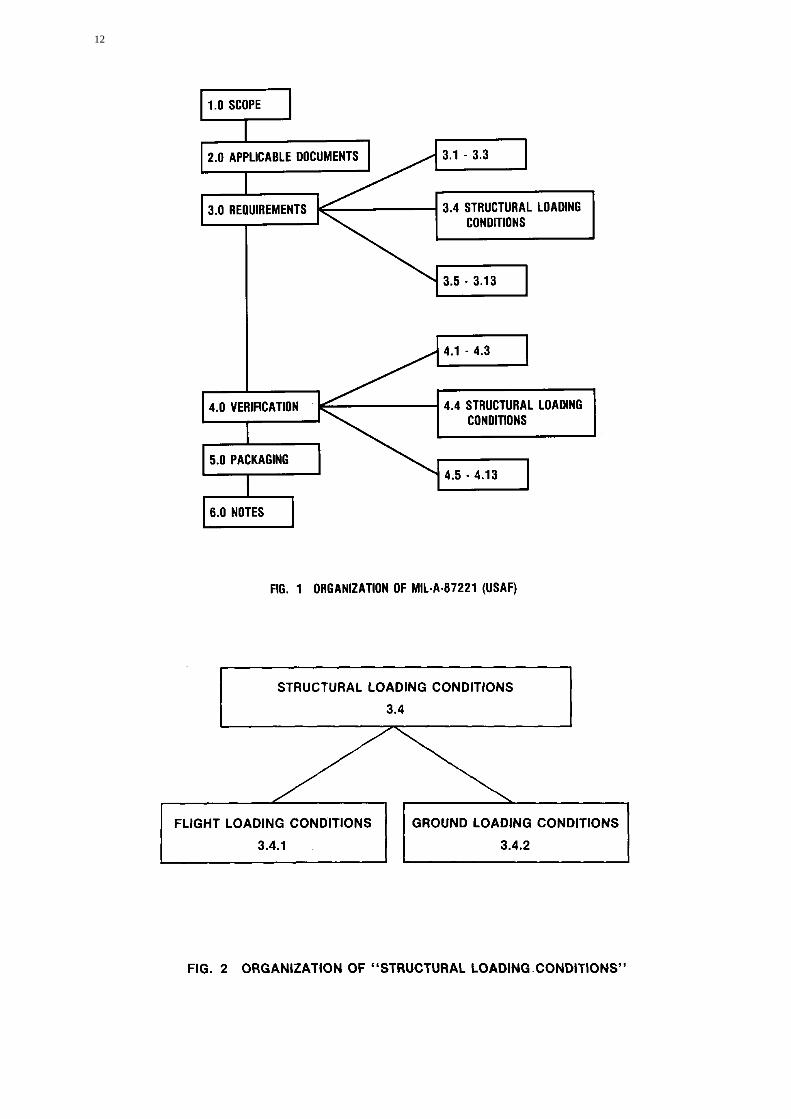
2.2.2 Structural Loading Condition
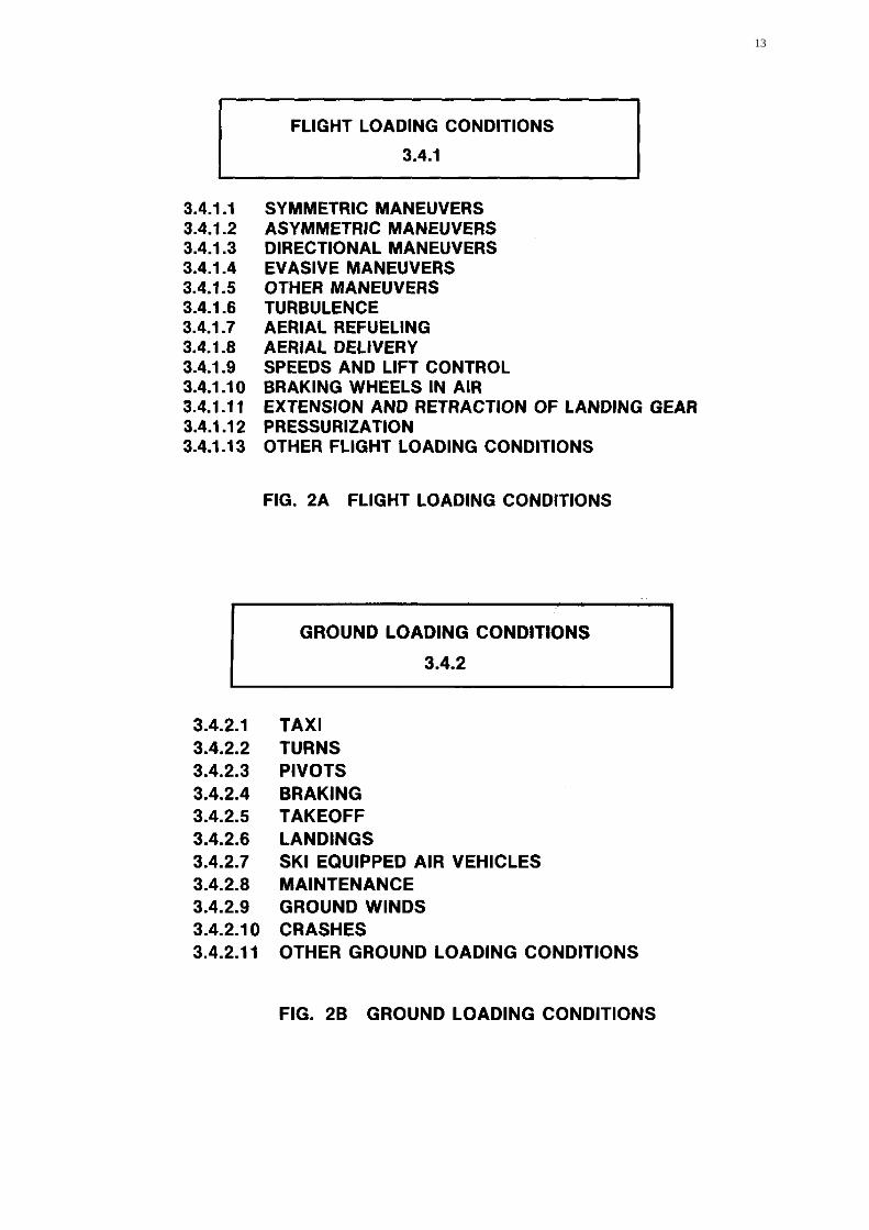
The general organization of MIL-A-87221 is shown infigure 1. Structural loading requirements are developedthrough the application of section 3.4 of the appendix.The verification of these requirements is established bythe use of section 4.4, also of the appendix. Thisprocedure when incorporated into the new specificationgives the user the best features of both a checklistapproach and total design freedom. The loadingrequirement section 3.4, is divided into flight and groundconditions as shown in figure 2. The flight and ground
10
conditions are divided into subsections as shown infigures 2a and 2b respectively. Each of the manysubsections contain various specific load sources whichthe designer can either accept or modify as appropriate.During aircraft design, particular care must be exercisedin defining both the structural loading conditions and theassociate distributions used to design the airframe, whichin turn directly influences the performance and reliabilityof the aircraft. No single section of the specification canbe addressed independently. All requirements pertainingto all technologies must be considered as one unifiedentity. Both flight and ground operating conditions mustbe based on the anticipated usage, unique to a specificaircraft design effort. These conditions reflect theoperational usage from which design loads shall evolve.
Even though this new approach gives the designerconsiderable flexibility, the designer is not abandoned toestablishing all requirements without guidance orassistance. In both the requirement and verificationsections, numerous possibilities are presented forconsideration. The applicability or non-applicability ofBach suggested requirement or verification can beindicated by inserting either "APP" or "N/A" in a blankprovided with Bach one. For those that are consideredapplicable, either the requirement or verificationprocedure is then fully defined. Additionally, uniquerequirements can be added as a direct product of thetailoring process.
2.2.3 Flight Loading Conditions
The flight conditions (subsection of 3.4) consists ofthirteen categories, from the Standard symmetricalmaneuvers, to missile evasion, to the all inclusive"Other" category which is the one that both frees thedesigner from rigid requirements and simultaneouslyburdens him with the need to better define anticipatedusage. The maneuver load category suggests a minimumof five sub-categories for consideration. There is, ofcourse, the usual symmetric maneuver envelope, figure 3.However, due to current usage, various maneuvers suchas extreme yaw, jinking, or missile lock evasion aresuggested for design consideration. Any maneuver whichis possible for an anticipated aircraft and its usage, mustbe considered for design purposes.
Other changes can be found in the area of turbulenceanalysis. Historically, gust loading conditions have beenanalyzed by a discrete approach. However, the currentprocedure is to employ an exceedence distributioncalculation. In order to establish the exceedencedistribution, various parameters are needed. Fortunately,the new specification does suggest values for these terms;figure 4 is an example from the specification. Also,historically, maneuver and gust loading were consideredindependent and non-concurrent of each other except foraircraft engaged in low altitude missions. However,MIL-A-87221 actually suggests the designer rationallyconsider various conditions where gust and maneuverloads are combined because they concurrently affect theaircraft.
A very different type of load condition occurs duringin-flight refueling. While some services use the probe anddrogue system, a few others use the flying boomapproach; a few use both types of in-flight refueling
systems. This specification provides guidance in boththese areas to establish appropriate design conditions.
Since the very beginning of aircraft pressurization,specifications have addressed its loading effects.However, this new specification addresses pressurizationin a more inclusive manner then in the past. Usually,pressurization concerns have been focused an cockpits orcrew compartments. In contrast, the new specificationaddresses all portions of the aircraft structure subject to apressure differential. The requirements to considerpressurization even apply to such areas as fuel tanks,avionics bays, or photographic compartments. The broadapplication of this section of the specification requiresconstant and capable vigilance by the designer to includeall pertinent structure.
Since this specification does not presume to directlyaddress all possible loading phenomena, a specialcategory is reserved for any unique situations. Thiscategory is called "other" and is available so the designercan completely define all anticipated aircraft flightloading conditions. The important aspect of this categoryis that the designer is free to include any flight loadingcondition derived from operational requirements that canbe appropriately defined for analysis
2.2.4 Ground Loading Conditions
While aircraft ground operations are not as glamorous asflight performance, they can be the source of significantloading conditions. Unlike flight conditions, there havebeen very few changes to ground operating conditions inrecent years. In some cases the loading levels have beendecreased due to improved civil engineering capabilities;improved runways, taxiways, ramps, etc. Ground loadingconditions include all ground operations (taxi, landing,braking, etc.) and maintenance operations (towing,jacking, hoisting, etc.).
2.2.4.1 Ground Operations
Since the earliest days of aircraft, ground operations havechanged very little. Most of these changes have been inthe area of load magnitude, not in the type or source ofload. Before takeoff, an aircraft normally needs to taxi,turn, pivot, and brake. Various combinations of theseoperations must be considered in order to fully analyzerealistic ground operations. The resultant loads are highlydependent on the operating conditions, which are in turndependent on the aircraft type and anticipated mission.
2.2.4.2 Takeoff and Landing.
Usually takeoffs and landings are performed on hardsmooth surfaces which are of more than adequate length.However, in some situations the surface is not ofadequate length, hardness, or smoothness. Therefore,takeoff specifications must either anticipate all possiblesituations or allow the designer to establish specifictakeoff and landing requirements for each system. Forexample, consideration is given to rough semi-prepared
11
and unprepared surfaces. Even rocket and catapultassisted launch is included in the specification. However,the designer is free to consider devices such as ski-jumps,if they are appropriate to the aircraft and missionsinvolved. Since takeoffs are addressed; so too arelandings. Various surfaces, arrestment devices anddeceleration procedures are included for consideration aspossible load producing conditions. The designer andeventual user must work together to correctly establishlanding requirements, since they can vary greatlydepending on the final usage of the aircraft.
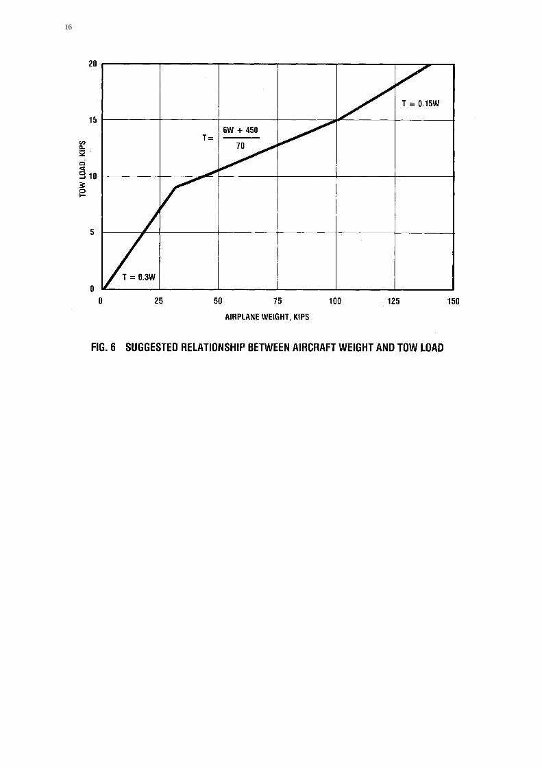
2.2.4.3 Towing
Since the beginning of aviation, it has been necessary totow aircraft. While the designer is free to define his owntowing conditions and associated loads, he must also toverify the legitimacy of these conditions. In this categorythe new specification comes close to the previous AirForce criteria specifications by providing the valuesgiven in figures 5 and 6. One should remember that thesetowing conditions are very much result of years ofempirical experience. Justifying and verifying newtowing load conditions could be a very difficult task.
2.2.4.4 Crashes
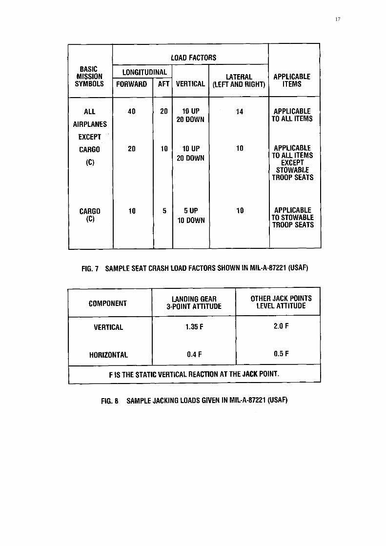
Unfortunately not all flights are successful; some end incrashes. Different types of aircraft require various typesof design considerations for crash loads, depending antheir inherent dangers due to mission and generalconfiguration. For example, fighters pose crash problemswith respect to seats, fuel tanks, or cockpit equipment,but definitely not litters or bunks. However, the design ofa transport would most assuredly involve crash loadconsiderations for cargo, litters, bunks, or even temporaryfuel tanks in the cargo compartment. The newspecification suggests various combinations of on-boardequipment. These suggested values, figure 7, are verysimilar to the historic ones which in the past were firmrequirements. Today a designer can use factors other thanthe suggested ones, as long as the alternate load factorscan be substantiated.
2.2.4.5 Maintenance
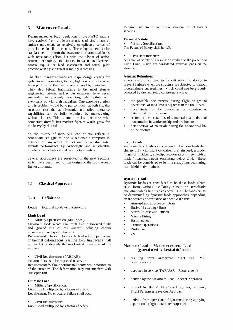
Even daily maintenance actions can impose variousloading conditions on aircraft. Many maintenanceoperations require towing, jacking, or hoisting whichsubject the aircraft to abnormal and unusual loadingcombinations that must be considered during aircraftdesign. General data is supplied for these conditions, seefigure 8. However, following the tailoring inMIL-A-87221 (USAF)., the designer is free to define anylevel of maintenance induced loading which can besubstantiated.
2.2.4.6 CONCLUSIONS
The new specification, MIL-A-87221, will allow designrequirements to be more closely tailored to theanticipated use of the aircraft. In this way the finalproduct will be more efficient, with less wasted,unneeded, and unused capabilities. This will lead in turnto reduce costs of ownership for Air Force weaponsystems. This specification has been applied to thedefinition of requirements for the Advanced TacticalFighter. This process is now taking place.
12
13
14
15
16
17
18
3 Maneuver Loads
Design maneuver load regulations in the NATO nationshave evolved from crude assumptions of single controlsurface movement to relatively complicated series ofpilot inputs in all three axes. These inputs need to bestandardized to permit the assessment of structural loadswith reasonable effort, but with the advent of activecontrol technology the hiatus between standardizedcontrol inputs for load assessment and actual pilotpractice with agile aircraft is rapidly increasing.
The flight maneuver loads are major design criteria foragile aircraft (aerobatics, trainer, fighter aircraft), becauselarge portions of their airframe are sized by these loads.They also belong traditionally to the most elusiveengineering criteria and so far engineers have neversucceeded in precisely predicting what pilots willeventually do with their machines. One extreme solutionto this problem would be to put so much strength into thestructure that the aerodynamic and pilot tolerancecapabilities can be fully exploited by maneuveringwithout failure. This is more or less the case withaerobatics aircraft. But modern fighters would grow fartoo heavy by this rule.
So the history of maneuver load criteria reflects acontinuous struggle to find a reasonable compromisebetween criteria which do not unduly penalize totalaircraft performance by overweight and a tolerablenumber of accidents caused by structural failure.
Several approaches are presented in the next sectionswhich have been used for the design of the most recentfighter airplanes.
3.1 Classical Approach
3.1.1 Definitions
Loads External Loads on the structure
Limit Load• Military Specification (MIL-Spec.):Maximum loads which can result from authorized flightand ground use of the aircraft including certainmaintenance and system failuresRequirement: The cumulative effects of elastic, permanentor thermal deformations resulting from limit loads shallnot inhibit or degrade the mechanical operations of theairplane.
• Civil Requirements (FAR,JAR):Maximum loads to be expected in service.Requirement: Without detrimental permanent deformationof the structure. The deformation may not interfere withsafe operation.
Ultimate Load• Military Specification:Limit Load multiplied by a factor of safety.Requirement: No structural failure shall occur
• Civil Requirements:Limit Load multiplied by a factor of safety.
Requirement: No failure of the structure for at least 3seconds.
Factor of Safety• Military Specification:The Factor of Safety shall be 1.5.
• Civil Requirements:A Factor of Safety of 1.5 must be applied to the prescribedLimit Load, which are considered external loads on thestructure.
General Definition:Safety Factors are used in aircraft structural design toprevent failures when the structure is subjected to variousindeterminate uncertainties which could not be properlyaccessed by the technological means, such as:
• the possible occurrences, during flight or groundoperations, of load levels higher than the limit load
• uncertainties in the theoretical or experimentaldeterminations of stresses
• scatter in the properties of structural materials, andinaccuracies in workmanship and production
• deterioration of materials during the operational lifeof the aircraft.
Static LoadsAirframe static loads are considered to be those loads thatchange only with flight condition: i. e. airspeed, altitude,(angle of incidence, sideslip, rotation rates, ..) etc. with aloads / loads-parameter oscillating below 2 Hz. Theseloads can be considered to be in a steady non oscillatingstate (rigid body motion).
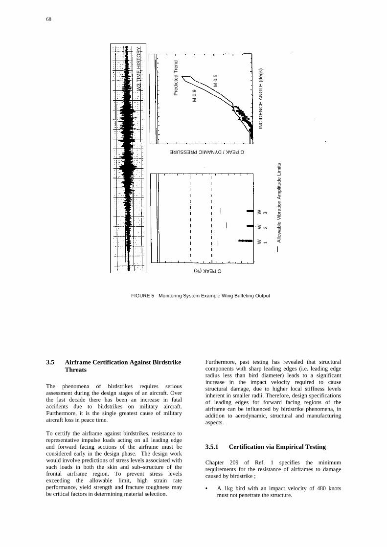
Dynamic LoadsDynamic loads are considered to be those loads whicharise from various oscillating elastic or aeroelasticexcitation which frequencies above 2 Hz. The loads are tobe determined by dynamic loads approaches, dependingon the sources of excitation and would include:• Atmospheric turbulence / Gusts• Buffet / Buffeting / Buzz• Stores Release and Jettison• Missile Firing• Hammershock• Ground Operations• Birdstrike• etc.
Maximum Load = Maximum external Load (general used as classical definition)
• resulting from authorized flight use (Mil.Specification)
• expected in service (FAR/ JAR – Requirement)
• derived by the Maximum Load Concept Approach
• limited by the Flight Control System, applyingFlight Parameter Envelope Approach
• derived from operational flight monitoring applyingOperational Flight Parameter Approach
19
• derived from load spectra (cumulative occurrencesof loads) applying Extreme Value Distribution
Maximum Load = the structure is capable to support(used in More Global Approach)
• Maximum load case which produces the maximumvalue of at least 1 failure strength criterion,integrating Load Severity Indicators.
3.1.2 Limit Load Concept
Strength requirements are specified in terms of
•••• Limit Loads• Military Specifications:
MIL-A-8860 (ASG),MIL-A-008860 A (USAF),AFGS-87221 A
is the maximum load normally authorized foroperations.
• Federal Aviation Regulations:Part 23,Part 25
is the maximum load to be expected in service.
•••• Ultimate Loadsis limit loads multiplied by prescribed factors of safety.
The basic premise of the Limit Load Concept is to definethat load, or set of loads, which the structure should becapable of withstanding without permanent deformation,interference or malfunctions of devices, degradation ofperformance, or other detrimental effects.
At any load up to limit loads, the deformation may notinterfere with safe operation. The structure must be ableto support ultimate loads without failure for at least 3seconds. The limit loads, to be used in the design of theairframe subject to a deterministic design criteria, shall bethe most critical combination of loads which can resultfrom authorized ground and flight use of the aircraft.
3.1.2.1 Conventional Aircraft
A limit load or limit load factor which establishes astrength level for design of the airplane and componentsis the maximum load factor normally authorized foroperations.
The determination of the limit loads is largely specifiedin the regulations (MIL, FAR, Def., etc) and isindependently of the missions / maneuvers actuallyperformed in operation. Worst case conditions are usuallyselected as a conservative approach.
Safety factors were introduced into the design of thestructure to take care of uncertainties which could not be
properly assessed by the technological means of thattime, such as:
• the possible occurrence of load levels higherthan the limit load
• uncertainties in the theoretical or experimentaldetermination of stresses
• scatter in the properties of structural materials,and inaccuracies in workmanship andproduction
• deterioration of the strength of materials duringthe operational life of the aircraft
3.1.2.2 Actively Controlled Aircraft
For actively controlled aircraft the limit loads are to bedetermined taking into account the flight control system(fly by wire, load alleviation) for:
• normal operating conditions, without systemfailures
• conditions due to possible system failures
The resulting loads have to be considered for designrespectively proof of the structure.
For civil aircraft required by recent regulations (FAR,JAR):
• for normal operating systemsas limit loads, ultimate loads applying theprescribed safety factor (1.5)
• for failure conditionsthe safety factor is determined by the failureprobability distinctive:
• active failure ( at time of failure )
• passive failure ( after failure for continuation offlight )
The purpose for the integration of an active controlsystem is to enhance maneuver performance while noteroding structural reliability, safety, and service life.The application is described in Ref. (1)
Reasons for applying other ApproachesFor conventionally controlled aircraft the regulationsgives unequivocal deterministic criteria for thedetermination of the most critical combination of loads.
e.g. for flight maneuvers, the regulations (Mil-A-8861)prescribe the time history of the control surfacedeflections and numerically define several essentialmaneuver – load parameter for the determination ofdesign load level.
20
Obviously with the introduction of active controltechnology, as well as care free maneuvering features,recent specifications no longer define the control surfacedeflections but rather provide the cockpit displacementsof the controls in the cockpit (Mil-A-8861).This means that existing design load regulations andspecifications based on conventional aircraftconfigurations, structural design concepts and controlsystems technologies, may not be adequate to giveunequivocal criteria for the determinations of designloads and ensure the structural integrity of future aircraftusing novel control methods.To cope with using the limit load concept for activelycontrolled aircraft several approaches have beenapplied:
• Maximum load conceptBackground and suggested models are described in3.2.1.
An example of application:
• The flight control system for a naturally unstableaircraft is designed with the feature to feed inmaneuver parameter boundaries ( load factors, rates,accelerations ) in such a way that limit design loadsare not exceeded.
This approach could lead to a reduction of the safetyfactor for flight maneuver loads keeping the structuralsafety at least as for conventional aircraft e.g. from 1.5 to1.4 for EFA.The application is described in Ref. (2).
Flight Parameter Envelope ApproachThe loads process is described in 3.2.5
Probabilistic determination of limit load
Operational Flight Parameter ApproachThe procedure is described in 3.2.2
3.1.2.3 References
[ 1 ] H.-M. Besch, H.-G. Giesseler, J. SchullerAGARD Report 815,Impact of Electronic Flight Control System (EFCS)Failure Cases on Structural Design Loads
[ 2 ] Sensburg O., Bartsch O., Bergmann H.Journal of Aircraft, Vol.24, No.11, Nov. 1987Reduction of the Ultimate Factor by applying aMaximum Load Concept.
3.1.3 Safety Factors Review
3.1.3.1 History
The present - day safety factor for aircraft structures, asapplied to manned aircraft, dates back 70 years. During
the last 30 years considerable progress has been made inthe fields of structural materials, semi finished productsand testing methods. Furthermore advances inaerodynamic and aeroelasticity, combined withdevelopments in electronic data processing, facilitate amore precise prediction of structural loads and structuralanalysis.
A reappraisal of the safety factor would therefore seem tobe in order, not with the intention of lowering the level ofsafety, but with the aim for examining the various safetyrequirements in the light of present knowledge. This,together with the fact that there exists a lack of a rationalbasis for the factors of safety concept presently appliedto the design of air vehicles, brought up a discussion ofchanging the structural safety concept and the factorsinvolved within AGARD-SMP in 1977. The Structuraland Materials Panel formed an ad hoc Group to conductthis discussion. Three pilot papers contained in Ref.(1)addressed the different aspects to be envisaged, and showup inconsistencies of the present concept as well asmeans and methods for permissible changes.The result of the discussion following the presentationsbefore the Sub - Committee was, that it would not beappropriate at the present time to change the concept, butit was found worthwhile to have a collection andevaluation of all those factors concerning structural safetyincluding the philosophies which back up the applicationof these factors.The Sub - Committee found it most suitable to collect allpertinent data and back up information by means of aquestionnaire, which was drafted by two coordinators(one for North America, one for Europe) and reviewed bythe members of the Sub - Committee.This questionnaire was distributed to the addressedAirworthiness Authorities of the NATO - Nations with arequest for cooperation. The replies of the questionnairewere summarized and evaluated by the coordinators andpresented before the Sub - Committee. The answersgiven, including the results of personal discussionsbetween coordinators and nominated representatives ofthe authorities, are condensed published in Ref.(2).From the evaluation it may be concluded that there existsa considerable amount of agreement with respect to theFactors of Safety and their application. On the otherhand, some disagreements and interpretations haveresulted. Thus, this report forms a basis for discussing thedisagreements in order to achieve a higher degree ofconformity between the authorities of NATO - Countrieswith a regard to structural safety and reliability.
At that time the present concept and the Factors of Safetywere in general regarded as satisfactory with the intentionto review the Safety Concept till such time as moreknowledge and experience in application of newtechnologies are available;e.g.• Improvement of knowledge about flight and ground
loads occurring in service (operational loads) toknow the margin between the design conditions andthe operational conditions.
21
• Introduction of new technologies, which are notincluded in the scope of the existing designrequirements
• active control
• behavior of new materials ( composites )
3.1.3.2 REFERENCES
[1] AGARD - Report No. 661Factors of Safety , Historical Development , State of theArt and Future Outlook.
[2] AGARD - Report No. 667Factors of Safety , Related to Structural Integrity .A Review of Data from Military AirworthinessAuthorities.
3.1.3.3 Possible Methods for Splitting of SafetyFactors
In the mean time significant progress and experiences inload determination for conventional aircraft and foractively controlled aircraft have been made as well asdeterminations of load conditions have been applied forcases which are not covered by the several existingairworthiness regulations; e.g. as special conditions.Therefore it is time to take up the review of the SafetyFactor Concept. Factors of safety can be rationalized bysplitting into Loads (FSl) and structural / materialuncertainties (FSs).The present - day safety factor covers the uncertainties asa global factor mainly applied for
• possible exeedances of loads in relation to thedesign loads
• uncertainties in structural analysis
without realizing the particular uncertainties of loads andstructural analysis separately i.e. the global factor isapplied as the same value for both. This application of thesame factor of safety for loads determination and forstructural analysis can lead to an apparent margin ofsafety which is higher or lower than the global factor isintended to cover.By splitting the factor into two parts, as suggested by theStudy Group Structures of AECMA (see chapter 3.2.1.1)for loads and for structural analysis, a clear relation of thesafety margin is determined.
• FSl for loads uncertainties
• FSs for structure uncertainties
The product of both factors is known, keeping theapproved total factor of 1.5 .
FS = FSl x FSs = 1.25 x 1.20 = 1.50
Another suggestion from US ( D. Gibson) is to divide theFactor of Safety into three terms
o U1 uncertainty related to loads computationo U2 ” ” to operational environmento U3 ” ” to structural analysis
In this proposal U1 and U3 are the same as FSl and FSs.U2 for predicting the actual operational environmentmight be applied using deterministic criteria. Theproposed values for all terms are 1.15.
e.g. U1 x U2 x U3 = 1.15 x 1.15 x 1.15 = 1.52
For aircraft which apparently will not be able to exceeddesign loads during operations e.g.
• applying operational maneuver models for derivingor updating of design loads (see chapter 3.2.4)
The value of U2 might be 1.0 resulting in a final Factorof Safety
FS = 1.15 x 1.15 = 1.32
3.2 Non Classical Approach
3.2.1 Maximum Load Concept
3.2.1.1 Background
The Airworthiness Committee of the international CivilAviation Organization (ICAO) discussed, among otherthings, the subject of maximum load concept in theperiod from1957 to 1970. It was decided in Montreal inlate 1970 not to pursue this concept for the time being asa possible basis for airworthiness regulations. Severalproposals however, were made to improve structuralsafety. This subject was also discussed by the StudyGroup Structures of the AECMA (AssociationEuropienne des Constructeurs de Material Aerospatial) inthe context of the Joint Airworthiness Requirement(JAR). These deliberations led to the suggestion to splitthe proven safety factor of 1.5 into two parts, in a rationalfashion, one for uncertainties in the loading(determination of loads), the other for uncertainties instrength analysis including scatter of material propertiesand inaccuracies in construction.
22
Allowable loads are defined as those load values that willonly be exceeded by expected loads with a prescribedsmall probability. These loads are then referred to asmaximum loads.Gust or landing loads are strongly influenced by randomphysical or human characteristics. But also in these casessafety could be much better defined by extrapolation ofloads from statistical data, rather than the application of asafety factor of 1.5 for all cases. Furthermore, loads thatare limited naturally by the ability of the aircraft toproduce them, or by internal aircraft systems, (loadalleviation, flight control systems) could be regarded asmaximum loads to which a safety factor need not beapplied. The determination of maximum loads with asmall probability of being exceeded is entirely possiblefor modern fighters which are limited in their maneuvers,or for control configured vehicles (CCV) which are inany case equipped with an active flight control system(fly–by–wire). As a principle the prescribed designboundaries and the corresponding safety factor should notbe applied separately, i.e. the entire design philosophyshould be considered. Therefore a mixed application ofvarious regulations to a single project is not advisable.Up to now the safety factor has been reduced in only afew cases. Within the pertinent regulations only the caseof the American MIL-A-8860 (ASG) issue is known,where no safety margin is required for the undercarriageand its supporting structure.It may be supposed that with the consent of theappropriate authorities the safety factor or the load levelcould be reduced in the following cases:
• in emergencies, such as emergency landings into anarresting net or cable
• for transient phenomena (hammer shock pressure inaircraft inlets)
• where actuators are power-limited and large loadscannot be produced
3.2.1.2 Suggested Models
The following models are proposed for the application ofthe Maximum Load Concept.
Semi-statistical / semi deterministicIn the past operational loads were predominantly checkedby measurement of the main load parameters, in the formof cumulative frequencies or load - parameter - spectra(Ref. 1).They are:
• the normal load factor, in flight and on the ground
• the angle of sideslip and/or the transverse load factor
• the rolling velocity in flight
• the bank angle during landing
On the basis of these load - parameter - spectra aprobability of occurrence of the main load parameters isdefined for each type of mission and maneuver, and themaximum value of the main load parameter can bedetermined from this.
If, for instance, an aircraft is designed for air-to-aircombat, a maximum load factor of 9.0 may be derivedfrom the statistical cumulative frequency distribution forevery tenth aircraft after 4000 flight hours. This value istaken to be maximum main load parameter. For this loadparameter the loads produced by the maneuvers specifiedin the pertinent regulations are determined by means of adeterministic calculation such that the maximum value ofthe main load parameter is just attained, but notexceeded. An example is the loads as a function of timeproduced by the actuation of cockpit controls accordingto MIL-A-008861.A recent approach for active controlled aircraft has beenapplied to the European Fighter (EFA) for thedetermination of the design loads, called Flight ParameterEnvelope Approach. ( Description see 3.2.5 )
Semi-statistical / semi empiricalIt has been known for years that VG and VGHmeasurements do not suffice for the definition of criteriafor structural design.In order to obtain statistically supported design criteria, aspecial NACA Sub-Committee on Aircraft Loadsrecommended (1954) to expand statistical load programsto the extend that they included measurements of timehistories of eight parameters, three linear accelerations (x,y, z,), three angular accelerations (p, q, r,), airspeed (V)and altitude (H).The first measurement of this kind where made with theF 105 D Fighter with the aim to develop a maneuver loadconcept which was to predict design loads (Ref. 2). Alldata were processed to calculate time histories of loads,with peaks called “observed loads”. The dataoscillogramms were examined in order to define 23recognizable types of maneuver. Assuming that for everytype of maneuver the same sequence of aircraft motionoccurs with the exception of differences in amplitude andduration, the measured parameters were normalized withrespect to amplitude and time.Finally, to determine the loads, the normalizedparameters were denormalized in order to get the loadpeak distribution for the wing, the fuselage, and theempennage. The good agreement between the observedand predicted load peak distribution demonstrated thefeasibility of the maneuver model technique for the F-105D aircraft. The F-106 Fighter was selected to demonstratethis model, thereby determining the model’s usefulnesson another aircraft. The detailed results of 3770 flight testhours made it possible to apply the maneuver modeltechnique i.e. the empirical calculation of componentloads as compared to F-106 design loads (Ref. 3).The results in the form of cumulative occurrence of theloads for wing, elevon, and vertical tail made it possibleto determine the design load for a given cumulativeoccurrence.
23
A recent approach has been elaborated in the WorkingGroup 27 of AGARD-SMP called Operational ManeuverModel. The demonstration of the feasibility is reported inAGARD Advisory Report 340 Evaluation of Loads fromoperational Flight Maneuvers (Ref. 4).(Description see 3.2.2 Operational Flight ParameterApproach)
Statistical: Extreme Value DistributionAs a rule, load spectra are produced with the objective ofdetermining magnitude and frequency of operationalloads. These, in turn, are used in fatigue tests todetermine the corresponding fatigue life of structure.Loads spectra like these are derived from relatively shorttime records, compared to the actual operational life time;they do not contain those maximum values that might beexpected to occur during the entire operational life of thestructure, i.e. a knowledge of which is necessary for thedesign.
Determination of Extreme Value DistributionIn cases where the range, the maximum value, and scatterof the spectrum may be safely assumed, an extreme -value distribution can be established, describing extremevalues of loads / load parameters by its magnitude andrelated probability of exceedences (suggested by Prof. O.Buxbaum, ( Ref. 5 )). By means of extreme loaddistributions the derivation of extreme loads is feasiblefor determinate probabilities of exceedences, and therebythe design load can be determined.
Examples of applications
• Maximum rolling moments on horizontal tailderived from in - flight measurement with C160Military Transport Aircraft, AGARD Report No.661, page 9
Fig. 1 shows the extreme – value distribution
• Maximum loads on vertical tail derived from in -flight measurements with F-106 Fighter AircraftAIAA - Paper No. 70-948, page 8
Fig. 2 shows the cumulative occurrences
3.2.1.3 References
[1] J. Taylor, Manual of Aircraft Loads,AGARDograph 83 (1965)
[2] Larry E. Clay and Heber L. Short,Statistical predicting Maneuver Loads from eight-channelFlight DataReport No. TL 166-68-1 (1/1968) NASA CR-100152
[3] James D. Jost and Guin S. Johnson,Structural Design Loads for Strength Fatigue computedwith a multi-variable Load Environment ModelAIAA - Paper No. 70 - 948
[4] AGARD ADVISORY REPORT 340Evaluation of Loads from Operational Flight ManeuversFinal Working Group Report of Structures and MaterialsPanel Working Group 27
[5] O. Buxbaum,Verfahren zur Ermittlung von Bemessungslastenschwingbruchgefährdeter Bauteile aus Extremwerten vonHäufigkeitsverteilungenLBF - Bericht Nr. FB - 75 (1967)
24
FIG. 1 EXTREME – VALUE DISTRIBUTION
25
FIG. 2 CUMULATIVE OCCURRANCES OF VERTCAL STABILIZER LOADS
26
3.2.2 Operational Flight ParameterApproach
3.2.2.1 Introduction
The determination of the design maneuver loads islargely specified in regulations independently of themaneuvers or missions actually performed in operation.For conventionally controlled aircraft the regulations givethe time history of the control surface deflections andnumerically define several essential maneuver – loadparameters for the determination of the design load level.Obviously with the introduction of the fly-by-wire and/oractive control technology, as well as care freemaneuvering features, recent specifications no longerdefine the control surface deflections but rather providethe cockpit displacements of the controls in the cockpit.This means that existing design load regulations andspecifications based on conventional aircraftconfigurations, structural design concepts and controlsystem technologies, may not be adequate to ensure thestructural integrity of future military aircraftconfigurations using novel control methods, structuralconcepts and combat tactics.
In service, maneuvers, especially combat maneuvers, areflown in accordance with practiced rules that lead tospecified motions of the aircraft in the sky. An evaluationof operational flight maneuvers has been made forseveral aircraft types flown by the USAF, CF and GAFwith the aim of deriving operational loads by applyingparameters measured in operational flights.
This approach is based on the assumption that maneuverstrained and flown by the NATO Air Forces can bestandardized.The standardized maneuver time history is thereplacement as a quasi unit maneuver, for all operationalmaneuvers of the same type.The Standardized Maneuver is obtained by normalizationof parameter amplitudes and maneuver time to make theparameters independent of mass configurations, intensityof the maneuver, flight condition, flight control system,and of the aircraft type.The goal is to find a standardized time history for eachtype of maneuver, which is independent of the extremevalues of the relevant parameters and aircraft type.
One promising approach is to derive design loads from acareful analysis of operational maneuvers by currentfighters to extract critical parameters and their range ofvalues. To investigate this approach, Working Group 27“Evaluation of Loads from Operational Flight Maneuver”was formed, AGARD involvement was particularlyrelevant since it allowed the expansion of the types ofaircraft and the control systems considered in the study.The Working Group formulated a set of activities thataddressed the fundamental premises of a method togenerate operational loads from flight parameters bydetermination of Standard Maneuvers independent of theaircraft type and the control system.
The flow chart in Figure 1 presents the general data flowand indicates the major phases of the procedure.These operational loads can be statistically evaluated foruse in static design and for fracture assessment.
In the first part of the procedure the verification of theOperational Maneuver Parameter Time Histories isdescribed in boxes with black frames, Fig 3.2.3.The steps of the verification are:
• Recording and Evaluation of Operational Parameters• Identification of the Maneuver Types• Normalization of the Parameters• Determination of the Standard Maneuver Types
In the second part the Derivation of Operational FlightLoads is described in boxes with red frames in 3.2.4applying the Maneuver Model in the steps:
• Selection of the Standard Maneuver Type to beconsidered
• Definition of the Boundary Condition as designcriteria
• Calculation of the Control Deflections necessary toperform the Operational Maneuver
• Response Calculation and Verification of theparameter time history
• Determination of Structural Loads
The evaluation of this procedure done by the WorkingGroup (WG 27) has demonstrated the feasibility ofdetermining loads from operational flight maneuvers(Ref. 1)
This Operational Flight Maneuver Approach can be usedfor:
• The judgment of the operational load level foraircraft already designed with regard to the designlevel (static and fatigue) as specified in theregulations.
• That means the margin between design loads and theextreme operational loads is known.
• The determination of the load level for static andfatigue design due to operation for new aircraft to bedeveloped.
3.2.2.2 References
(1) AGARD ADVISORY REPORT 340Structures and Materials Panel, Working Group 27on Evaluation of Loads from Operational FlightManeuvers.
(2) AGARD REPORT 815Loads and Requirements for Military Aircraft, Page3 –1, and Page 4 – 1
27
Fig. 1: Procedure Overview
3.2.3 Determination and Verification ofOperational Maneuver Parameters andTime Histories
3.2.3.1 Verification Performed
Based on the hypothesis that all operational maneuversperformed in service can be verified as standardmaneuvers ( normalized parameter time histories for eachindependent maneuver type ) the determination ofoperational loads is feasible applying the OperationalFlight Parameter Approach. The verification of thisapproach to generate operational loads from flightparameters by determination of a set Standard Maneuversconsisting of normalized operational parameter timehistories is described.The Standard Maneuver procedure is shown in figure 2 asa flow chart.For each type of Standard Maneuvers the normalizedmotion parameters are to be validated independent ofaircraft type, mass configuration and flight controlsystem.
For the evaluation of operational parameters, thefollowing data were made available and have beenjudged as applicable.
• Flight test data by GAF Test Center for specificoperational maneuvers on three aircraft ( Alpha Jet,F – 4 F, Tornado)
• Data from simulations by GAF for specificoperational maneuvers recorded on Dual FlightSimulator for two aircraft ( F – 4, JF – 90 )
• Service data by USAF recorded on the F-16(selected subset from over 300 sorties from 97aircraft )
• Service data by CF recorded on the CF-18 fleetmonitoring) (selected subset of CF-18 fleetmonitoring )
Taking all data available, which have been found to besuitable for separation into maneuver types, the data baseis about 13 maneuver types.For two maneuver types, High - g – turn and Barrel roll,more than 60 maneuvers for each maneuver type havebeen considered as applicable for evaluation.
Recorded Operational Parameters
C B
Operational ParametersTime Histories
Standard Maneuver Type A
C B
NormalizationProcess
Maneuver Type A
C B
Boundary Conditions
Maneuver Type A
Aircraft Basic Data
M A N E U V ER M O D E L
Structural LoadsStatic Design and / or Fatigue
Maneuver Identification
Flight-Test-Data Service-DataSimulation-Data
28
The actively controlled aircraft ( Tornado, F-16, CF-18 )fit in the same scatter band as the conventional controlledaircraft. This means the hypothesis that the operationalmaneuvers are performed in the same way, i.e.performing the same normalized parameter time history,can be considered as confirmed.
The result is, that the Operational Standard Maneuverindependent of the aircraft type is applicable as unit inputfor calculation of the movement of a specific aircraft byreconstitution of the real aircraft configuration and flightcondition.
3.2.3.2 OPERATIONAL PARAMETERS
The number of parameters defining the aircraft motionshould be chosen in such a way that recording andevaluation cause minimal expense. This can be achievedby using parameters available from existing systems ofthe aircraft. Each aircraft motion must be represented bya data set of relevant parameter time histories.
The following operational parameters are necessary:
Ma Mach-numberAlt Altitude
n(x) Longitudinal Load Factorn(y) Lateral Load Factorn(z) Normal Load Factor
p Roll Rateq Pitch Rater Yaw Rate
t Maneuver Time
the Eulerian Angles, if available:
φ Bank Angleθ Pitch AltitudeΨ Heading
and additional parameters only for the verificationprocess:
α(alpha) Angle of Attackβ(beta) Angle of Sideslip
ξ(xi) Aileron / Flaperon Deflectionη(eta) Elevator Deflectionζ(zeta) Rudder Deflection
3.2.3.3 STANDARD MANEUVER PROCEDURE
Provided the operational parameter time histories of thebasic parameter are available in correct units, thisprocedure includes several steps:
(1) Maneuver type identification
(2) Normalization of relevant parameter time historiesfor a number of identified maneuvers of the samemaneuver type for comparison
(3) Determination of the mean values for each relevantparameter time history of the same maneuver type
(4) Idealization and tuning of the parameter timehistories
(5) Determination of the standard maneuver timehistories
The result of this procedure is a data set of standardizedparameter time histories. The parameters are roll rate,pitch rate and yaw rate of the selected maneuver type.See Figure 2.
29
FIG 2: Standard Maneuver Procedure
30
3.2.3.4 MANEUVER IDENTIFICATION
The goal of the maneuver identification is to select therelevant maneuver segments from the recordedoperational data base. A maneuver is identified bycomparing the observed data with the predefinedmaneuver characteristics as described in the ManeuverType Description of selected maneuvers:
TurnN(z) ≤ 2, p ≥ ± 20°/ sec, φ ≈ 40 ÷ 90°
Roll steady to bank angle, pull, the bank angle is held aslong as desired, opposite roll back to level
Roll rates of opposite sign before and after g peak.
High g TurnN(z) > 2Turn Maneuver
BreakN(z) > 3
High g Turn Maneuver with g peak during initialmaneuver time.
ScissorsA series of High g Turn Maneuvers
Roll ReversalN(z) >2, p >±20°/sec, φ ≈ 20 ÷ 90°
Roll steady to bank angle, directly opposite roll back tolevel.
High g Rolls / Barrel RollsN(z) > 1.5, p > ± 20°/sec, φ (max) ≈ 360°
Roll steady in one directionBarrel Roll over top θ rise to a peak value . Barrel rollunderneath θ descend to a negative peak value.
Pull sym.N(z) > 1.5 ∆ φ < 10°
From ≈ 1g to ≈ 1g
The maneuver identification parameters are mainly loadfactor n(z), roll rate p and bank angle φ.
First:The data are checked for completeness and suitability forseparating them into missions and maneuver types.
Second:The start and end time of each maneuver type areidentified when the roll rate is near zero and the g isapproximately 1.The bank angle also indicates the type of maneuver, i. e.full roll φ ≈ 360°, half roll φ ≈ 180°, turn < 90°
Figure3 :Identified Time Histories of Correlated Operational Parameters
31
FIG 4: Unified Roll Directions
FIG 5:Normalizsation of Parameters
32
Figure 3 shows as an example for the identification of aHigh g Turn Maneuver. In this case the roll rate traceprimarily defines the maneuver length.The pilot first rolls the aircraft in the direction of the turnand finally rolls it back to the wings level position. Inparallel, the g rises to a peak value. The peak is held aslong as desired. The g drops down from its peak as theaircraft is rolled back to the wings level.The start and the end of the maneuver are determined asfollows: the maneuver starts when the first negative /positive deflection of the roll rate trace starts and themaneuver finishes after recovering i.e. the oppositedeflection of the trace, decreased to zero.
The Eulerian angles φ, θ, Ψ,give the aircraft orientationwith respect to the earth’s coordinate system.
The bank angle values indicate the type of maneuver asdefined in Maneuver Type Description.
All recorded parameters are time related.
3.2.3.5 NORMALIZATION
Normalization is necessary because several maneuvers ofthe same type are different in roll direction , amplitude ofmotion and in maneuver time. For the calculation ofloads from operational maneuvers it not important toseparate the maneuver types into different roll directions.
Therefore, maneuvers of the same type are transformedinto a unified roll direction. See Figure 4.
For a requisite comparison, a two – dimensionalnormalization is necessary.Figure 5 illustrates the basic procedure of normalization.The ordinate presents one of the parameters of motion :y= n(y), n(z), p, ........for several maneuvers of the sametype : y(1), y(2), ........y(n).These parameters are normalized by relating them to themaximum values (absolute derivation from zero) whichhave occurred. This means the maximum value of eachnormalized parameter becomes in this case:
Y= y(1)max = y(2)max = + 1.0
The time is presented by the abscissa t , where by themaneuver executing time is marked by t(1), t(2), .......t(n)for several maneuvers.The normalization is accomplished in that way that:
• firstly, the maneuver time is chosen as the value 1.0 i. e.t(1)= t(2) = T = 1.0• secondly, the extreme values of the relevant parametersis chosen at the same normalized time.
The time scale normalization factor for all correlatedparameters: n(y),n(z),p, q, r, φ, θ, Ψ, within, foreexample, a High g Turn was derived from the roll ratetrace. See Figure 6
FIG 6: Correlated Parameters
33
FIG 7: Normalized Roll Rate Trace
FIG 8: Time Ratio
34
Fig.9 Shifted Roll Rate Traces
Fig. 10 Comparison of Normalized Rate Traces
35
In the normalized time scale, T=0 corresponds to the timewhen the roll rate trace first goes negative or positive(start of the maneuver ), and T=1 corresponds to the timewhen the roll rate trace is back to zero after the oppositeroll rate peak (finish of the maneuver). Figure 7 showsthe normalized roll rate trace (positive roll direction).
This normalization procedure is dependent on theaccurate maneuver start value. (p≈0)
In several cases the start values of the available timeslices are very poor. One reason is the low sample rate ofe.g. 1 or 2/sec. Recordings from flight tests are sampled24 times per second.An other reason is the selected parameter thresholdvalues of the data reduction and maneuver identificationprocess, combined with a low sample rate.For these cases an upgraded normalization procedure,derived from the basic procedure, is used.
The estimated time of a High g Turn t(m) had a veryhigh correlation with the difference between the time ofthe first and the second roll rate peak. See Figure 8. Thistime ratio is very important for the normalizationprocedure
The time transformation from real time into normalizedtime requires several steps:
1. Determination of time ratio. The time ratio is definedby t`(1)= dt/t(m)2. Harmonization For the comparison of the parametertraces, a harmonization of the maneuver time ratio isnecessary.
sfn = scale factor
3. Shifting A new interpolation of a similar number oftime steps for each of the correlated parameters for allmaneuver of the same type is necessary Then the roll ratetraces were shifted in a way, that all selected first peakscoincided at the same time step.
All correlated parameters are shifted parallel in thesimilar way.
Figure 9 presents the comparison of the shifted roll ratetraces versus normalized time for the selected High gTurn maneuvers.
The amplitudes of the traced are normalized individually.Each value of the trace is divided by its absolutedeviation value from zero, therefore, all normalizedamplitudes will fall between ±1.0.Figure 10 shows the result of the “peak to peak”normalization procedure.
The application of the two-dimensional normalizationprocedure is very helpful for the comparison of maneuvertime histories. In this normalized form, all parameter timehistories are independent of the aircraft type.
3.2.3.6 MEAN VALUES
After normalization of the maneuver time, for all selectedmaneuvers of the same type, the typical values of therelevant parameters – in this case the peaks of the rollrate – coincide at the same normalized time. Eachparameter time history contains the similar number oftime steps, independent of is individual maneuver length.This is the basis for calculating the arithmetic meanvalues for each of the time steps.
Figure 9 presents the comparison of the non- normalizedroll rate traces versus normalized time for the selectedHigh g Turn maneuvers. The roll rate is a good examplefor all relevant parameters.Note: The amplitudes for the mean value calculation arenot normalized.
The mean value is defined by:
y j
y j
nm
i
i
n
( )( )
= =∑
1
n = number of maneuver of the same type
j = time step
yi (j) = relevant parameter
ym (j) = mean value
The mean values of all parameters have been formed incombination by smoothing of the time history.For plot comparison, a normalization of the amplitude isnecessary.
3.2.3.7 IDEALIZATION
The mean value traces represent a good estimation of therelationship between the selected parameters during amaneuver (e. g . High g Turn ).For the compensation of any minor errors by the meanvalue calculation and for reasons of compatibility, themean values have to be idealized and tuned.The interpretation of “idealized and tuned” as follows:To cover the most extreme peaks of the control surfacedeflections possible, the most extreme accelerations inroll (p), pitch (q), and yaw (r ) are used.These values are obtained by linearization of theacceleration time history in a way that the same responseof the aircraft is obtained.
For the idealization, the calculation is performed in threesteps.
nn sftsftsftsft ∗′==∗′=∗′=∗′ .....332211
36
�yy
x=
∆∆
In the first step, the following parameters werecalculated:
The three angular accelerations p, q and r bydifferentiating the three angular rates p (roll), q (pitch)and r (yaw) with respect to maneuver time.
The differentiation was given by
In the second step, the acceleration traces p, q, r, werereplaced by linearized traces
With respect to the zeros of the traces and extremevalues of p, q, r and thecorresponding extreme values of roll -, pitch- and yawrate.
Figure 11 presents the comparison of derived rollacceleration trace and idealized trace versus maneuvertime for a High g Turn Maneuver.
In the third step, the three angular rates (roll, pitch,yaw) were recalculatedBy integrating the idealized values of the three angularaccelerations (p, q, r).
FIG 11 : Idealization Traces
FIG 12: Standard Maneuver
For the reasons of compatibility, the idealized data haveto be tuned, that means the relation between the three
Eulerian angles Φ, Θ Ψ and the angular rates p, q, r isverified with the equations:
The result is the standardized maneuver.
Figure 12 presents the idealized and tuned “standardized”traces of the three angular rates for a High g Turnmaneuver.For each type of standardized maneuver the normalizedmotion parameters are independent of aircraft type, massconfiguration and flight control system.
3.2.4 Flight Loads derived from OperationalManeuvers
The determination of operational loads is considered asfeasible applying an Operational Maneuver Model. Theessential input for the Operational Maneuver Model is aset of Operational Standard Maneuvers consisting ofnormalized operational parameter time histories, asdetermined in 3.2.3.The operational loads can be determined by introducingaircraft basic data, flight condition and boundaryconditions for the maneuver to be considered.
3.2.4.1 Application of the Operational ManeuverModel
The application of the Operational Maneuver Model isfeasible for the determination of loads in general.
� for Extreme Operational Loads / Limit Loads takinginto account the boundary conditions for design
� for Fatigue Loads by building a usage spectrummade up of reconstituted Operational StandardManeuvers
� for Loads related to recorded parameters taking intoaccount the recorded parameters directly withoutapplication of standardization procedure(normalization, mean values, tuning, idealization)and without tailoring by boundary conditions
Aircraft Basic Data
Aircraft basic data is the main input for the OperationalManeuver Model and is required to perform thereconstitution from the standardized maneuvers.
q = ∗ + ∗ ∗� cos � sin cosΘ Φ Ψ Φ Θ
p = − ∗� � sinΦ Ψ Θ
r = − ∗ + ∗ ∗� sin � cos cosΘ Φ Ψ Φ Θ
37
For calculation of the control deflections necessary togenerate the operational parameter time history, thefollowing data are needed:
• Aerodynamic data set for the aircraft Cl, Cm= f(α),Cy, Cl, Cn = f(α,β)
• Flight Control System data• for conventionally controlled aircraft: mechanical
gearing / limits
• for active controlled aircraft: flight control law(EFCS)
• Engine data- thrust
• Flight Condition- airspeed, Ma– altitude
3.2.4.2 For calculation of structural loads onaircraft components the following data areneeded:
- aerodynamic data set for the components to beconsidered (wing. tailplane)- mass data for the components to be considered
3.2.4.3 Boundary Conditions as Design Criteria
Boundary Conditions have to be considered as the maininput for defining the load level.This is necessary for the determination of the extremeoperational maneuvers and consequently for theverification of design loads.
The boundary parameters to be defined for an operationalmaneuver are:
→→→→ Design Maneuverso the shortest maneuver time (Tman = minimum)o realizable by the control system and the
aerodynamic limitso the maximum vertical load factor ( nz )o the maximum lateral load factor ( ny )o the maximum bank angle (φ) for the maneuver
to be considered
These boundary condition parameters can be derivedfrom spectra of main load parameters by applyingextreme value distributions, an example is shown inFigure 13.If no spectra are available the main load parametersstated in the Design Requirements ( MIL – Spec. ) can beapplied.
→→→→ Fatigue ManeuversAll the main load parameters can be taken from relatedspectra available.
The procedure of Operational Maneuver Model isshown in Figure 14 as a flow chart.
Using the Standardized Operational Parameters thereconstitution into real time is performed.For these operational parameters time histories in realtime the control deflections necessary to generate theoperational maneuver can be determined as follows:→ roll control ξ by applying roll and yaw equations
→ pitch control η using the pitch equation, taking intoaccount the symmetrical aileron deflections
→ yaw control ζ by applying sideslip and yaw equations
Using these control deflections the response calculation isdone for real time conditions, but for the purpose ofchecking the results with respect to the standardizedmaneuvers, the response parameters are normalized.In a comparison of the parameters between input andoutput, the standardization is checked. In case ofconfirmation of the conformity of the main responseparameters with the standardized parameters, the outputparameters are considered to be verified. These verifieddata represent the model parameters for load calculation.The calculation of the Operational Loads is performed inthe conventional manner applying the verified modelparameters in particular the control deflectionsdetermined for the Operational Maneuver to beconsidered.
38
FIG 13 : Boundary Conditions for Design Maneuvers
39
FIG 14 : Procedure of the Operational Maneuver Model
40
3.2.5 Flight Parameter Envelopes Approach
Abstract
This part of the manual will explain in detail the FlightParameter Envelope Approach:
A new method to determine the critical flight design loadsfor a modern control configured fighter aircraft. The wayfrom the initial design phase up to the Final OperationalClearance (FOC) will be examined.
The Flight Parameter Envelope Approach has to be seenin conjunction with the new design tools (i.e. LoadsModel) and the modern digital Flight Control Systemswith carefree handling and load limiting procedures. Thedefinition of Flight Parameter Envelopes will then beuseful and feasible if computer tools are available to doextensive load investigations for the total aircraft underbalanced aircraft conditions and if the FCS will limit theaircraft responses (carefree handling) and with it theaircraft loads (load limiting system).
The definition of Flight Parameter Envelopes may be aproblem for new aeroplanes where in the beginning ofthe aircraft development only limited information aboutthe aircraft responses from previous or similar aircraft isavailable. New techniques, such as thrust vectoring forhigh angle of attack maneuvering in combination withhigher dynamic pressures may cause new problems. Butthe poststall flight conditions up to now known are onlyloads critical locally because the dynamic pressures inthe flown poststall regime is low.
However for aircraft like the Eurofighter generation thedefinition of Flight Parameter Envelopes is a useful andfeasible approach to determine the critical flight designloads and to overcome the additional problem thatMilitary Specifications became more and more obsoletefor aircraft design.
List of Symbols
A/C AircraftALE Allowable Loads Envelope
CFC Carbon Fibre Composites
DOF Degree of FreedomFCS Flight Control System
FOC Final Operational Clearance
HISSS Aerodynamic Program - HigherOrder Panel Sub- and SupersonicSingularity Method
IFTC Initial Flight Training Clearance
MAST Major Airframe Static Test
MAFT Major Airframe Fatigue Test
MLA Maneuver Load Alleviation
RF Structural Reserve Factor
flimit Limit Load Factor
fult. Ultimate Load Factor
Fx, Fy, Fz Forces
Mx, My, Mz Moments
c. g. center of gravity
qdyn dynamic pressure
nx, ny, nz load factors
p roll velocity
q pitch velocity
r yaw velocity
pdot roll acceleration
qdot pitch acceleration
rdot yaw acceleration
α angle of attack
β sideslip angle
β∗ qdyn product of sideslip angle anddynamic pressure
ηF/P foreplane deflection angle
ηT/E trailing edge deflection angle
δR rudder deflection angle
3.2.5.1 Introduction
When starting with feasibility studies for a new fighteraircraft in the beginning of the eighties indications froman aircraft designed in the early seventies were confirmedthat a change of the applications of MilitarySpecifications for the aircraft design would be necessary.This was also valid for the evaluation of aircraft designloads (e.g. MIL-A-08861A).
The increase in new technologies e.g.
increase of computer capacity
digital flight control systems (FCS)
new materials – e.g. Carbon Fibre Composites (CFC)
better and more efficient design tools – e.g. StructuralOptimization Tool, Loads Model, etc.
led to a change of the design and performancerequirements for a new fighter generation.
The high work load of the pilots should be reduced incontrast to the increase of the tasks of the aircraft such asperformance, agility, etc.. The consequence was to design
an aerodynamic unstable aircraft - increase of agilitywith a digital Flight Control System (FCS)
The requirement to reduce the workload of the pilot couldbe fulfilled by a carefree handling and automatic loadlimiting procedure in the FCS control laws. With it thecontrol function of the pilot for the instrument panel inthe cockpit is reduced to a minimum and eyes out of thecockpit whilst maneuvering is possible.
To overcome the new situation for calculation of criticaldesign loads for modern fighter aircraft the so calledFlight Parameter Envelope Approach was developed andwill be described here for an aerodynamically unstableaircraft with foreplanes (see Fig. 1) featuring:
41
• artificial longitudinal stability
• extensive control augmentation throughout the flightenvelope
• carefree maneuver capability with automatic loadprotection achieved by careful control of maneuverresponse parameters
Fig. 1 - “Demonstrator Aircraft” for Flight ParameterEnvelope Approach
The main problem is to realize an agile and carefree loadlimiting FCS. Therefore a robust structural design of theairframe is necessary including an appropriate growthpotential for possible changes of the FCS control lawscovering aircraft role changes which may influence thedesign loads and with it the aircraft structure. To makesure that the airframe and the FCS are harmonized:aircraft structure and FCS control laws have to bedeveloped concurrently.
In comparison to earlier aircraft like Tornado the designloads for the new FCS controlled fighter aircraft have tobe defined without a detailed knowledge of the finalstandard of the FCS because
a very limited understanding of the FCS- control lawsis available in the initial design phase.
This problem can be solved by the definition of newStructural Design Criteria where among other designconditions the principal flight maneuver requirements forthe aircraft have to be defined. In this case the FCSdependent loads critical Flight Parameter Envelopes (s.Fig. 2) are defined by:
translatory accelerations (ny, nz)
rotational velocities (p, r)
rotational accelerations (pdot, qdot, rdot)
sideslip conditions (β∗ qdyn)
etc.
To take into consideration all requirements of thedifferent aircraft design disciplines the Flight ParameterEnvelopes have to be defined in not only consideringFCS but also
Flightmechanics
Aerodynamics
Structural Dynamics
Loads
Fig. 2 – Loads Critical Flight Parameter Envelopes for the Loads Model – Interdependence between the Flight ParameterEnvelopes and Critical Design Load Cases for Main A/C- Components
42
The calculation of aircraft design loads will be done witha modern computer tool the so called Loads Model andthe Flight Parameter Envelopes are a part of this tool.
3.2.5.2 The Flight Parameter Envelope Approachand the Loads Model
Both the FCS dependent Flight Parameter Envelopes(Fig. 2) and the Loads Model (Fig. 3) result in a highlyefficient computer tool for aircraft design loadcalculations:
- the maneuver requirements of the aircraft controlledby the FCS are indirectly defined by the FlightParameter Envelopes and the Loads Model containsall the important aircraft mass and aerodynamicinformation’s which have to be known to calculatethe critical design loads for the aircraft
3.2.5.3 Description of the Loads Model
The today’s computer capacities allow extensive loadinvestigations considering:
- all mass information’s (masses, c.g.’s, moments-of-inertia, mass distributions) for the total aircraft andspecific aircraft components
- the corresponding aerodynamic information(aerodynamic pressures, aerodynamic coefficients/derivatives) for the total aircraft and the definedaircraft components for different Mach numbers
- the static aeroelastic input (flexibility factors andincrements for total aircraft and aircraft
components) to correct the rigid aerodynamics(aerodynamic pressures, aerodynamic coefficients/derivatives) for defined Mach numbers.
The mass- and aerodynamic data have to be stated fordifferent loads critical aircraft configurations.
The idea of the Loads Model is to calculate the criticalaircraft component design loads (aircraft componentloads envelopes) to get balanced load cases for the totalaircraft. That means the total sum of the aircraftcomponent forces and moments is zero (equilibrium) foreach load case:
Σ Fx,y,z = 0 Σ Mx,y,z = 0
These balanced load cases (Fig. 4) are the basis for thecalculation of nodal point loads for the total aircraftFinite Element Model (FE-Model) and for the stressanalysis.
Simplified the Loads Model is a combination of big input
and output data files and a number of computer programs(Fig. 3). The input data sets contain all information whichis necessary for load calculations while the output datasets contain the results of the load calculations as loadcase conditions, forces, moments, aircraft componentload envelopes, etc..
The computer programs of the Loads Model can beclassified into two different groups
- programs to establish and to handle the required datasets
- programs to compute the critical aircraft componentloads (balanced load cases, loads envelopes)
Fig. 3 – Loads Model - Overall View
43
Fig. 4 – Total Aircraft – Balanced Load Case
To use the Loads Model efficiently the structural designrules including the flight maneuver requirements have tobe defined for the new aircraft. This will be done in theSDC.
3.2.5.4 Structural Design Criteria (SDC)
Because more and more the Military Specifications (e.g.MIL-A-08861A) are getting obsolete for the design ofmodern fighter aircraft it becomes important to define thenew structural design rules in the Structural DesignCriteria.
The following conditions have to be defined in theStructural Design Criteria:
Design Flight Envelope- Mach/altitude
nz-max./min. vs. Mach
flimit, fult. - limit/ultimate load factor
Loads critical aircraft configurations with andwithout stores – key configurations
Aircraft design masses:
Basic Flight Design Mass, Maximum Design Mass,Minimum Flying Mass, Landing Design Mass, etc.
Gust conditions:
gust design speeds in combination with aircraftspeeds, gust lengths
Temperatures:
maximum recovery temperature
maximum stagnation temperature
Ground Loads Criteria:
sink rate, crosswind, arresting, repaired runway, etc.
Departure and Spin
Hammershock conditions
Bird strike conditions
Static aeroelastic requirements
Flutter/divergence requirements
Fatigue conditions:
safe life or fail save philosophy
g-spectrum, scatter factor, aircraft service life, etc.
etc.
Additional to the above described design conditions also
the principal flight manoeuvre requirements for theaircraft
have to be defined.
3.2.5.5 Flight Parameter Envelopes for StructuralDesign
The application of the single axis pitch, roll or yawmaneuvers (MIL-A-08861A) is no longer sufficient forthe definition of design loads (Fig. 5 and Fig. 6).
0.0 0.5 1.0 1.5 2.0 2.5
-15
-10
-5
0
5
10
15
Time (s)
Y T
itle
Vertical Load Factor Angle-of-Attack Pitch Rate Taileron Pilot Input
Fig. 5 – MIL - Pull-Push Maneuver
0.0 0.5 1.0 1.5 2.0 2.5 3.0 3.5 4.0 4.5 5.0
-6
-4
-2
0
2
4
6
8
Time (s)
Vertical Load Factor Angle-of-Sideslip Lateral Load Factor Taileron Roll Rate Roll Acceleration Yaw Rate Pilot Input
Fig. 6 – MIL - Rolling Pull Out Maneuver
The carefree maneuver capability with automatic loadprotection allows the superposition of combined pilotcontrol inputs in roll, pitch and yaw and with it numerousdifferent operational maneuvers which have to be takenunder consideration to find the critical design loads.Some typical pilot stick inputs for flight clearancemaneuvers are shown in Fig. 7.
44
Fig. 7 – Typical Pilot Stick Input
The following Flight Parameter Envelopes have to bedefined (s. Fig. 2):
nz = f(qdot)
ny = f(rdot)
nz = f(p, pdot, r, rdot, ny, β*qdyn)
p, r vs. pdot, rdot
As it can be seen mainly the inertia dominated parametersas the translatory accelerations (nz, ny) and the rotationalvelocities (p, r) and rotational accelerations (pdot, qdot, rdot)have to be defined while only one aerodynamicparameter is β∗ qdyn (sideslip angle ∗ dynamic pressure).The sideslip angle β is well controllable by the FCS andwith it the product β∗ qdyn. β∗ qdyn can be defined underconsideration of the gust requirements for the aircraft.
Important for the definition of the Flight ParameterEnvelopes for the structural design of an aircraft are alsothe possible tolerances of the flight parameters (s. Fig. 8).These have to be defined
Fig. 8 – Flight Control System Design - Tolerance of Flight Parameter
- For example:
to define nzmax./min. for the most important FlightParameter Envelopes
nz = f(qdot)
nz = f(p, pdot, r, rdot, ny, β*qdyn)
it should be known how exact the FCS controls thevertical load factor nz (s. Fig. 8):
nz = nz max./min. ± ∆nz
If in this case the defined tolerances are to small anincrease of the nz overswing (±∆nz) may causeproblems, because the load limiting procedure ofthe FCS can become uncertain therefore or on theother hand an increase of the critical aircraft loadshas to be accepted for which the aircraft structurehas to be checked for.
These Flight Parameter Envelopes will be used now todetermine the design load and the load envelopes for theaircraft main components – see Para. 3.2.5.8.
The interdependence between the Flight ParameterEnvelopes and critical design load cases for the differentaircraft components can be seen on Fig. 2.
3.2.5.6 Total Aircraft and ComponentAerodynamics
To get “balanced load cases” the total aircraftaerodynamic as well as the corresponding componentaerodynamic is integrated in the Loads Model regardingall loads critical aerodynamic influences. The result mustfulfil the condition:
- sum of component aerodynamics = total aircraftaerodynamics
The following aerodynamic data sets are part of theLoads Model:
- aerodynamic pressures of the total aircraft for allaerodynamic influences (α, β, control surfacedeflections, p, q, r, etc.) for different Mach numbers
- the corresponding aerodynamiccoefficients/derivatives of the aircraft components -result of aerodynamic pressure integration – for alldefined monitor stations (Fig. 9)
- the corresponding aerodynamiccoefficients/derivatives of the total aircraft – sum ofcomponent coefficient/ derivatives
- the static aeroelastic corrections of the aerodynamicpressures for all aerodynamic influences as
α, β, control deflections, p, q, r, etc.
and the aerodynamic pressures of aeroelastic inertiaeffects and the corresponding integration results(coefficients/derivatives) for
nz, ny, pdot, qdot, rdot
together with the correction factors and incrementsfor the aerodynamic coefficients/derivatives for theaircraft components and the total aircraft
- the corrected flexible aerodynamic pressuresincluding the corresponding flexible total aircraftaerodynamics and the flexible aircraft componentaerodynamics
45
The main programs for establishing the requiredaerodynamic data sets and for data set handling are:
- a theoretical aerodynamic program (e.g. the DasaHISSS program – higher order panel method) tocalculate the rigid aerodynamic pressures for theabove described loads relevant aerodynamicinfluences.
In Fig. 10 it is shown how starting from a CATIAmodel the HISS panel model will be derived.
- a correlation and integration program to compareand correct the theoretical total aircraft aerodynamicresults up to first total aircraft wind tunnelmeasurements and with it to correct the aerodynamic
Fig. 10 – HISSS Panel Model of “DemonstratorAircraft” – Calculation of Aerodynamic Pressures
for Total Aircraft
- pressures and the aerodynamic coefficients/derivatives for the aircraft and the aircraftcomponents
- a static aeroelastic program to calculate theaeroelastic pressure increments for the correction ofthe rigid pressure distributions and to calculate thecorrection factors and increments for theaerodynamic coefficients/derivatives for the aircraftcomponents and the total aircraft to establish theflexible aerodynamic data set.
an aerodynamic pressure summation program tosummarize the aerodynamic pressures due to
α, β, control deflections, p, q, r, etc.
for the selected critical load cases to calculate theaerodynamic nodal point loads for the FE- Model.
3.2.5.7 Total Aircraft- and Component Masses
For the calculation of “balanced load cases” the massconditions for the defined design masses (Basic FlightDesign Mass, Maximum Design Mass, Minimum FlyingMass, Landing Design Mass, etc.) for the total aircraft as
aircraft mass
aircraft c.g.
aircraft moments of inertia
as well as the corresponding component mass conditionshave to be integrated into the Loads Model.
- Sum of component masses = total aircraft mass
Fig. 9 - Load Monitor Stations for “Demonstrator Aircraft” and Corresponding Main Loads Components
46
The following mass data sets are part of the LoadsModel:
- the aircraft component masses, component c.g.’s andmoments of inertia including the correspondinginternal fuel states and external stores (Fig. 9 – A/CMonitor Stations)
- the total aircraft mass, c.g., moments of inertiaincluding the internal fuel states and external storesas sum of the above described aircraft componentmasses
3.2.5.8 Aircraft Loads Monitoring
The calculation of critical design load cases (loadsmonitoring) for the aircraft components (monitorstations) can be started when the required input data setsfor the Loads Model are established. The outcome of theaircraft loads monitoring are Loads Envelopes (Fig. 11)for the defined monitor stations.
The computer program which will be used for thecalculation of critical load cases under consideration ofthe defined Flight Parameter Envelopes is the so called“Balance Program”. The loads analysis for the monitorstations (Fig. 9) will be performed by means of userdefined dynamic equilibrium points (time steps of a timedependent flight simulation):
- The user has to define for each load case thefollowing flight parameters
respecting the Flight Parameter Envelopes (Fig. 2)and as a special case for this “demonstrator” aircraft
the foreplane deflection (ηF/P) and trailing edgedeflection (ηT/E-sym.)
under consideration of the foreplane schedule
- The Balance Program will define the remainingones:
α, β, η-T/E-sym. or η-F/P, η-T/E-unsym., δ-R
and nx and the thrust level
if required. In a second step the corresponding air-,inertia- and net- loads for all monitor stations arecomputed for the selection of critical design loadsto establish the loads envelopes for the definedaircraft components
To be sure that the defined requirements will be fulfilledthe program also checks
- the derived control surface deflection anglescompared to the max. deflection angles
- the derived hinge moments for the control surfacescompared to the max. defined hinge moments ifnecessary
- the user defined flight parameters compared to theFlight Parameter Envelopes
It seems to be useful to establish a program for loadscalculations which can be used for different degrees offreedom (DOF):
- 6 DOF – balance of Fx, Fy, Fz, Mx, My, Mz
- 5 DOF - without Fx balance (tangential force)
- 3 DOF – balance of Fx, Fz, My for pure symmetricconditions
- 2 DOF – balance of Fz, My for pure symmetricconditions without Fx balance
It should also be possible later on in the aircraft clearancephase when the carefree handling and load limiting FCSis available to use a flight simulation program to do timedependent loads critical flight simulations and tocalculate the corresponding flight load time histories (air-, inertia-, net- loads for all time steps) for the aircraftmonitor stations with the Loads Model.
Fig. 11 – Example of Loads Envelopes for Monitor Stations – Design Load Cases
47
To fulfil the above described additional program checkfunctions the following margins have to be defined:
- max. deflection angles for control surfaces versusMach number
- max. allowable hinge moments for the controlsurfaces respective max. normal forces if necessary -as result of structural optimization of wing, fin andforeplane
- engine thrust conditions if necessary
- Maneuver Load Alleviation (MLA) concept if theFCS will have a MLA procedure – to reduce thewing bending moment – respective the other in Para.3.2.5.13 described load reducing FCS rules
- as a special case for this “demonstrator” aircraft theforeplane trim schedule including possibletolerances because the foreplane and the trailingedge flaps will be used for symmetric flight control
After the feasibility studies respective definition phasethe normal development process of an aircraft structurehas three phases:
- Design Phase
- Check Stress Phase
- Structural Clearance Phase
For these three development phases the accuracy of theinput data (aircraft masses, aerodynamic, etc.) for theLoads Model differs and with it the accuracy of the loadcalculations. But as explained before the standard of theinput data for the Loads Model is relatively high even atthe beginning of the aircraft development due to moderncomputer tools (i.e. theoretical aerodynamic programs)and the possible crossreading to other similar aircraft.
But more important is that with the Flight ParameterEnvelopes the principal flight maneuver requirements forthe aircraft can be defined very early and with it theinteraction of FCS and the aircraft loads. During thedevelopment of the aircraft structure the Flight ParameterEnvelopes have to be checked in line with the FCSdevelopment.
3.2.5.10 Design Phase
Before starting loads calculations with the 1st flexibleLoads Model in the Design Phase the in Para. 3.2.3.8described prerequisites have to be settled additional to theFlight Parameter Envelopes to be sure that the loads arethe critical ones and are not maximized:
- A structural optimization has to be done and with itan optimization of the control surface efficienciesunder consideration of aeroelastic influences, failureconditions and deflection rates (Fig. 12). Based onthese optimization studies the critical hingemoments respective normal forces for the controlsurfaces can be defined. The result of optimization is“configuration freeze”.
- The max. deflection angles versus Mach number andthe maneuver conditions for the control surfaceshave to be defined – for example the foreplane trimschedule.
- A maneuver load alleviation (MLA) concept shouldbe defined if necessary under consideration of
the required reduction of wing root bendingmoment for high g conditions
the trailing edge split flap schedule as functionof g respective α
the foreplane trim schedule.
Fig. 12 – Flexible Loads Model -Static Aeroelastic Influences
If all these prerequisites are defined and integrated in theLoads Model the load investigation can start.
During the Design Phase the Loads Model consists oftheoretical linear aerodynamics compared with firstwindtunnel test results and corrected if necessary. Theflexible aerodynamic data set includes all important staticaeroelastic corrections for selected Mach/altitude points(Fig. 13).
Fig. 13 – Flight Envelope Mach-Altitude Points forFlexible Loads Model – Flexible Aerodynamic Data Set
The main benefit to do the load investigations with thefirst flexible Loads Model is
- the loads for the aircraft components can becalculated for total aircraft balanced conditions fordifferent aerodynamic configurations (with andwithout stores) and different aircraft masses (fuel,external stores) under consideration of the FCSrequirements (Flight Parameter Envelopes).
48
3.2.5.11 Check Stress Phase
The Check Stress Phase is the second development phase.The design loads have to be checked and updated withthe updated Loads Model for the design of the productionaircraft structure:
- the panel model for the theoretical aerodynamiccalculations has to be updated (configurationchanges, external stores, etc.)
- the new theoretical linear aerodynamic has to beupdated by comparing and correcting it to the latestwindtunnel tests (configuration changes, additionalstore configurations, mass flow, etc.)
- first windtunnel based store aerodynamic incrementscan be available (store balances) and can beincluded in the Loads Model
- the static aeroelastic corrections have to be updatedby using the updated structure (FE- Model) and theupdated aerodynamic pressures
- the aircraft masses have to be updated forproduction aircraft standard
- the foreplane trim schedule and the tolerances forthe trim schedule have to be updated
- the MLA concept has to be checked and updated ifnecessary
- the max. hinge moments for the control surfaceshave to be checked and updated if necessary
- if required additional monitor stations have to beincluded in the Loads Model
- the Flight Parameter Envelopes have to be checkedand updated in line with the FCS development. Thatmeans in detail that the flight control laws have tobe reviewed during all design phases to check theirfunction as a load limiting system. For example thedefined tolerances of the Flight ParameterEnvelopes have to be checked, e.g. the nz tolerances:
nz max./min. ± ∆nz
as explained in Para. 3.2.5.5.
As for the Design Phase the load calculations have to bedone by using the Balance Program and the updatedFlight Parameter Envelopes. The up to now availableFCS has only a check function because the carefreehandling and load limiting procedures are not finallyagreed (preliminary carefree handling). The loadinvestigation should be expanded and additionalMach/altitude points should be considered.
The revised aircraft component design load cases(balanced load cases, load envelopes) from the CheckStress Phase are the basis for the stress analysis for theproduction aircraft and with it for the structural clearanceactivities in the Clearance Phase.
3.2.5.12 Structural Clearance Phase
The aircraft clearance will be done in different steps fromthe first flight clearance for the prototypes up to theInitial Flight Training Clearance (IFTC) and the FinalOperational Clearance (FOC - 100% load level) for theproduction aircraft.
The aircraft structure has to be cleared for the conditionsdefined in the Structural Design Criteria as there are:
design flight envelope (Ma/altitude)
critical aircraft configurations
limit/ultimate load factor
aircraft design masses
nz-max./min. vs. Mach
etc.
Fig. 14 – Allowable Load Envelope for AircraftClearance Phases – Structural Reserve Factors < 1.0 are
considered
For the clearance of the aircraft structure so calledAllowable Loads Envelopes (ALE) will be used. TheALE’s (Fig. 14) contain the structural information of theprototypes respective of the production aircraft. TheALE’s have to be defined by the stress office based onthe design load envelopes of the aircraft components andunder consideration of the results from the stress analysisand structural tests. To be on the severe side during theclearance activities (flight test) only structural ReserveFactors (RF) < 1.0 have to be considered in the ALE’s.
The prerequisites to increase the clearance level are :
- Major Airframe Static Test (MAST) to limit,ultimate, failure load condition and other aircraftcomponent tests - to check the aircraft structure
- FCS updates – from preliminary carefree handling tofull carefree handling to check the load limitingprocedure of the FCS
- Validation of the Loads Model via the Flight LoadSurvey to update the data basis for loads monitoringand to proof also the load limiting procedure of theFCS
The first Loads Model for the structural clearance of theaircraft consists of non-linear aerodynamic data based onwind tunnel pressure plotting measurements. Thevalidation of this non-linear Loads Model will be done bythe Flight Load Survey. The Flight Load Survey will beperformed for selected primary aircraft configurations(clean aircraft and external store configurations). Duringthe Flight Load Survey aerodynamic pressures of thesurfaces (wing, foreplane, fin) and the fuselage will be
49
measured (Fig. 15). The integrated pressures(aerodynamic coefficients for the total aircraft and foraircraft components) will be correlated against the loadpredictions from the non-linear Loads Model. The LoadsModel will be than corrected where significantdiscrepancies exist. Finally the flight validated LoadsModel for the primary aircraft configurations is availableand should be used for the Final Operational Clearance(FOC) – 100 % load level and production FCS.
During the Structural Clearance Phase at all clearancelevels the confidence that the load level will not beexceeded has to be shown by the loads monitoring ofloads critical flight simulations using the current FCS andthe validated Loads Model. Some typical pilot stickinputs for the flight simulations (flight clearancemaneuvers) are shown on Fig. 7.
The loads from the simulated flight maneuvers have to becompared to the Allowable Loads Envelopes for eachmonitor station. If the loads monitoring shows that theloads are inside the ALE’s the clearance step is fulfilled.If not:
- the areas have to be defined where control lawchanges are required to maintain acceptable loads
or
- modifications may be necessary to improve theaircraft structure for higher loads
3.2.5.13 Load Optimized Maneuvers
In the past the aircraft were optimized mainly toaerodynamic performance conditions (drag, etc.) and thedesign loads were the result of the aerodynamicconfiguration, the aircraft mass conditions and theapplication of single axis pitch, roll or yaw maneuvers(e.g. MIL-A-08861A).
A new possibility for the latest high performance fighteraircraft generation like Eurofighter are load optimizedmaneuvers because the FCS can be used in some casesfor load reduction under the consideration that the aircraftperformance is not prejudiced.
Three examples for load optimized maneuvers controlledby the FCS are given below:
1. Load optimized foreplane/trailing edge deflectionschedule as a special case for the “demonstrator”aircraft described in this paper:
a) reduction of front fuselage loads
The front fuselage loads are normallydominated by the inertia loads. To reduce thefront fuselage loads (Fz -normal force and My -vertical bending moment) the foreplane has tobe deflected in that way that the aerodynamicforeplane loads are acting against the frontfuselage inertia loads (s. Fig.16 ). In this casethe aircraft has to be controlled by the trailingedge flaps.
b) reduction of trailing edge flap loads - e.g.hinge moments.
For low g conditions (1g) where the maximumroll performance of the aircraft is required thetrailing edge flaps can be zero loaded for theaircraft trim conditions by trimming the aircraftonly with the foreplane. The trailing edge flapitself has to be deflected in that way that the αinfluence on the flap will be compensated:ηT/E-symm(nz=1.0)= f(α, Mach, A/C-cg)With it the flap hinge moments can be reducedand the roll efficiency of the aircraft can beincreased in some cases.
Fig. 15 – Flight Load Survey - Pressure Transducers at the Prototype of “Demonstrator Aircraft”
Procedure a) may be used only for the front fuselageloads critical flight conditions as high g’s turns at lowaircraft masses (minimum flying mass) where the normalaerodynamic discharge for the front fuselage is aminimum and with it the net load is a maximum. In thiscase the trailing edge flap loading is relatively lowcompared to the maximum aircraft rolling conditions andcan be used therefore for exclusive aircraft control in thepitch axis. In all other cases the aircraft performance willbe more important.Procedure b) is a possible solution for hinge momentreduction if the control surface loads are increasing andthe size of the flap actuators cannot be changed.
the shift of the aerodynamic center of pressuretowards the wing root reduces the wing rootbending moment and with it the wingattachment load conditionsIn this case the i/b- flap has to be deflecteddownwards to increase the wing lift in theinboard wing area while the o/b- flap has to bedeflected upwards to reduce the lift in theoutboard wing area under the condition that thetotal wing lift has not to be changed (s. Fig. 17).This differential trailing edge flap deflectionhas to be superimposed to the full span trailingedge flap trim condition. The small effect onthe aircraft trim conditions by using the MLA-system has to be corrected by a full spantrailing edge deflection itself or by theforeplane.
Fig. 17 – Maneuver Load Alleviation (MLA) Change ofWing Lift Distribution and Shift of Center of Pressure
The MLA- system could be important at highg’s and high dynamic pressure in the lower α-region (elliptical wing lift distribution, linearaerodynamics).At higher α there may be a natural shift of thecenter of pressure to the wing root because thewing lift distribution becomes more and more atriangle due to non linear aerodynamics. (s. Fig.18).
Fig. 18 – Spanwise Normal Force Distribution NaturalShift of Center of Pressure to the Wing Root
The MLA- system can be important for the critical wingup bending conditions at max. g’s for the static designrespective the most critical g’s (mean proportional g’s)for fatigue design because the aerodynamic design oftendidn’t allow to increase the lever arm of the wing rootattachment to carry over the wing bending moment by acouple of forces (s. Fig. 19).
3. Prevention of overswing of control surfaces(deflection angles):
to prevent load peaks on the control surfacesduring rapid aircraft maneuvers (e.g. rapidrolling) an overswing of the control surfacesshould be avoided. An example for the trailingedge flap is shown on Fig. 20. In this case theoverswing of the flap is optimized by a smallchange of the T90 condition and with it the flaploads (hinge moments) are reducedsignificantly.
Fig. 19 – Wing Root – Carry Over of Wing BendingMoment
The above described maneuvers can be defined for thecritical static design loads as well as for fatigue loadswhich becomes more and more important for thestructural design of the aircraft.
51
In all these cases it must decided whether the loadoptimized maneuvers sacrifice aircraft performance orwhether the benefit (i.e. mass saving) is big enough tocompensate the loss of performance!
Fig. 20 – Dynamic Overswing of Trailing Edge Flaps – Change of T-90 Conditions
One way to assess this question is to evaluate requiredoperational maneuvers with respect to extreme or fatiguemaneuvers as evaluated by the former AGARD-WG 27(AGARD AR 340). For further information see Chapter3.2.2 – Operational Flight Parameter Approach.
On the other hand the β∗ qdyn requirement defined in theflight parameter envelopes (s. Fig. 2) is also a loadlimiting condition controlled by the FCS as explained inPara. 3.2.5.5. With it the Fin loads and the side force andside bending moment of the rear and front fuselage canbe limited.
3.2.5.14 Ultimate Load Factors
Historically a reduction of the ultimate load factor fult.
was done several times down to fult.=1.5 now which wasfor a long time seen as the lowest possible limit.
The situation was changed for FCS controlled aircraftwith carefree handling and load limiting procedures.
Based on the assumption that the aerodynamic and inertiaflight loads for the aircraft are limited by the FCS bycontrolling the important flight parameters
β, p and nz respective α
directly the ultimate load factor can be reduced forexample from
fult.=1.5 to fult.=1.4
(as agreed with the British-, German-, Italian- andSpanish- authorities for the Eurofighter)
But as explained in Para. 3.2.5.12 an extensive FlightLoad Survey has to be done to verify the load limitingprocedure of the FCS and to proof the reduction of theultimate load factor.
For FCS independent loads (e.g. landing gear loads,Hammershock pressures, etc.) the ultimate load factorwill still be 1.5.
For further information about the ultimate load factor seeChapter 3.1.3 – Safety Factor Review.
3.2.5.15 Conclusion
The calculation of aircraft loads under consideration ofFlight Parameter Envelopes is useful and practicable formodern high performance fighter aircraft with a carefreehandling and load limiting FCS.
As demonstrated for the Eurofighter:
- the integrated design of FCS and aircraft structure ispossible
- the carefree handling and load limiting procedure ofthe FCS is working
- the defined design loads by using the FlightParameter Envelopes are acceptable and leading to arobust but not to conservative design of the aircraftstructure - compared to the loads evaluated with theFCS (time dependent flight load simulations) lateron in the A/C- Clearance Phase the design loads arewell
- the reduction of the ultimate load factor from f-ult =1.5 to f-ult = 1.4 based on the FCS- load limitingfunction is useful and leads to a lighter aircraftstructure
On the other hand the enormous increase in systemcomplexity for a modern high performance fighteraircraft with a carefree handling and load limiting FCSleads to extensive investigations:
- the flight control laws have to be reviewed during alldesign phases to check their function as a loadlimiting system
- the necessary careful and accurate loadinvestigations during all design phases are veryextensive
- an extensive Flight Load Survey has to be done forLoads Model validation and with it to proof the loadlimiting procedure of the FCS and additional ifnecessary to proof the reduction of the ultimate loadfactor
- the ALE concept has to be verified by detailed stressanalysis, static test and possible restrengthening ofthe aircraft structure
As explained above the permanent monitoring of thestructural design parameters as Flight ParameterEnvelopes, ALE’s, etc., is indispensable to minimize therisk of a non optimal structural design of the aircraft.
Therefore it should be emphasized once more thatvarious disciplines as Loads, Aeroelastics,Flightmechanics, Flight Control, Stress, Aerodynamics,Flight Test have to cooperate in a very close manner, theso called concurrent aircraft engineering.
52
3.3 Dynamic Loads
3.3.1 IntroductionThe intention of this chapter is to discuss the predictionof unsteady loads arising as a result of pilot actions (asopposed to atmospheric turbulence, say). Gusts andground loads are treated in separate chapters. Loads dueto buffet and buffeting, hammershock, gunfire and storeejection/release loads are mentioned. The aim is met bybriefly describing the background, prediction processesand calculation methods, and certification issues.Consideration of the latter is essential, even at the designstage. In addition, the likely way forward for this“technology” is noted. A table is provided as a guide forconsideration of dynamic loading sources and theireffects on an airframe.
In addition, examples of dynamic load analyses andtesting for validation purposes are given in section 3.4,whilst birdstrike is discussed in 3.5. The latter does notstrictly come within the terms of this chapter, but isclassified under ‘threats’. However, it is such asignificant source of aircraft in-service incidents, andhence a driver of future designs, that it is included here.
In the course of the item, reference is made to somespecific papers and work known to the author. However,it should be noted that hundreds of technical papersrelating to the overall subject are available world-wide.Since there are several approaches documented, thischapter does not make prescriptive statements regardingthe “correct” approach. Rather, readers are encouragedto adopt information and data applicable and appropriateto their own specific technical challenges. The aim is toraise awareness, not define methods in detail.
The airframe static load can be thought of as one thatchanges only with flight condition e.g. airspeed, angle ofincidence, altitude etc. For the purposes of this report,the airframe dynamic load component can be consideredto be the oscillating part of the load which has afrequency in the range 2 - 100Hz. This is not a hard andfast rule. However, loads oscillating below 2Hz can beconsidered to be due to 'rigid body' motion. Above100Hz, the load is unlikely to be adversely affecting amajor structural item, more likely to be a localized effecte.g. an acoustic, stores or equipment environmentaleffect.
There are many sources of dynamic loads on a militarycombat aircraft. Traditionally, combat aircraft were notdesigned and optimized to the degree that is expectedtoday. Dynamic effects were therefore included in theearly design phases of an aircraft project by applying afactor to the static design loads (which were usuallymaneuver defined for combat aircraft). The pessimismthat this introduced could be tolerated and covered themajority of dynamic loading effects. It was only whenstructural or equipment problems emerged during projectdevelopment, or even in-service, that dynamic loads wereconsidered in more detail. This situation wascompounded by an absence of advanced unsteadyresponse prediction tools.
The performance of modern military combat aircraft hasincreased, taking the airframe into situations where the
airflow over the structure becomes separated andoscillatory. The unsteady environment to which amodern airframe is subjected has therefore becomeincreasingly harsh. At the same time, a requirementexists to reduce the factors applied to the design loads todrive down structural mass. The need to predict theunsteady load component more accurately, to ensuresafety, has therefore become correspondingly moreimportant. To that end, modern military combat aircraftare designed to withstand the worst static and dynamicload cases which they are likely to encounter in-service.This has led to some regions of modern combat aircraftstructures being designed by dynamic load cases.
3.3.2 Types of Dynamically Acting Loads
3.3.2.1 Buzz
Buzz is a single degree of freedom flutter wherebylimited amplitude oscillations of surface panels or controlsurfaces occur due to a loss in aerodynamic damping andmay involve the local resonance of such surfaces. Thisloss is attributed to boundary layer and shock waveinduced instabilities in the surrounding flow field.Examples of such instabilities include oscillations ofshock waves over a control surface and separated flowcaused by an upstream shock wave.
Although the limited amplitudes of oscillation associatedwith buzz phenomena do not cause catastrophic structuralfailure, as can happen with a two (or more) degree offreedom flutter, structural fatigue can arise. Commonsolutions to reduce the adverse effects of buzzphenomena include manipulation of the flow field (e.g.using vortex generators) to reduce instabilities andstiffening of the control surface hinges to reduce freeplay.
3.3.2.2 Buffet and Buffeting
Buffet is an excitation caused by the separation of airflow over a surface. This can be separation in anunsteady manner causing excitation of the surface fromwhich it is separating, or separation from upstreamcomponents such that the resulting unsteady flowimpinges upon a downstream surface. This is worse athigh angles of attack. Buffeting is the associatedairframe structural response. Buffet and buffeting arephenomena that are unavoidable in highly maneuverablecombat aircraft.
For many years fighter aircraft have had to penetrate intothe buffeting region of the flight envelope in order to gainmaximum turn performance. With conventional controlsystems, the buffet onset was in many ways a usefulfeature because it provided the pilot with a clear warningthat he was approaching the limits of aircraftcontrollability. Increasing buffet penetration, for instanceby increasing angle of attack, is also accompanied byrelated characteristics such as wing-rock and nose slice.
With the advent of complex, active flight controlsystems, modern aircraft can remain controllable wellbeyond traditional boundaries, and even into post-stallconditions. This has implications upon structural designdue to the potentially greater time spent in unsteady flow
53
conditions (fatigue implications) and the large magnitudeof these unsteady loading actions (strength).Consequently, the ability to predict these flows hasassumed a far greater importance in aircraft design.
Another consequence of active flight control systems isthe potential for affecting the structural response underunsteady loading conditions. If the system interpretsstructural response as aircraft response and tries tocorrect it by driving the controls, then there is a potentialfor increasing the loads on the structure. This area ofexpertise is known as Aero-servo-elasticity (ASE) orStructural Coupling. A well-designed flight controlsystem (FCS) will not exhibit such adversecharacteristics. It is not a design driver when assessingloads, but an awareness of the total system (aircraft +FCS) characteristics is required for flight clearance work.
Ways of using active control for reducing structuralresponse to unsteady loading, like buffet, are underconsideration. A view of this is given in reference 1.
The above is applicable to combat aircraft. However,buffet also occurs due to impingement of vortical andwake flow on downstream surfaces, separated flow overcontrol surfaces, and flow interaction between adjacentstores (or engines), their pylons and other airframestructure, to name a few generic examples. These are notrestricted to highly maneuverable aircraft. Indeed,straight and level flight at transonic conditions, on anyclass of aircraft, can lead to complex shock-boundarylayer interactions, which induce separated flow and hencebuffet, i.e. a forced response.
Further ’buffet inducers’ include excrescence andcavities. Examples of the former include blade aerials,chaff/flare dispensers, auxiliary cooling system intakesand exhausts. Flow separation occurs from these unlessthey are carefully designed, and faired-in specifically toavoid this phenomenon. The result is unsteady pressurefluctuations on surrounding, external paneling andsurfaces. The risk here is that surface panel modalfrequencies can be excited which can lead to rapidfatiguing of the affected structure.
Flow spillage from cavities can have similar effects. Thecavities can be those occurring when the landing gear isdeployed, or when internally carried weapons arereleased. The latter is likely to be much more of aproblem due to the wider range of flight conditions atwhich it may occur.
Further, there is much potential for adversely affectingthe internal and back-up structure of the weapons bay dueto acoustic effects. Similarly, stores and equipmentinstalled in the bay will have difficult environmental
clearance issues to overcome. Control of such acousticenvironments is a major study area.
3.3.2.3 Hammershock
Hammershock (H/S) is an event whereby an aircraftengine surges, sending a pressure pulse upstream,opposing the direction of airflow that would exist duringnormal engine operation. This results in a loss of engineperformance, the possibility of a flame-out and/orpermanent engine damage.
H/S events can occur anywhere within a combat aircraftflight envelope but are more significant at the envelopeextremities. They have many causes. These include:
A single surge may occur or a series of pressure pulsesmay be generated if the surge becomes 'locked-in' i.e.conditions are such that repeated surges occur.
The pressure pulse created impinges on the engine intakeand on the forward fuselage. Both of these items musthave sufficient strength to withstand a H/S event. This isparticularly critical for aircraft which have foreplaneslocated in the path of the pulse. The concern here is thata locked-in surge may occur with a pulse frequency closeto a fundamental foreplane vibration mode. If an item ofstructure is excited at a frequency near one of its naturalvibration modes (i.e. a resonant frequency), the resultingamplitudes of vibration and hence load are large.
Realistic prediction of the excitation can be achieved bydeliberately surging an engine on the ground andmeasuring the resultant pressure pulse amplitudes in theintake duct, splitter plate/lip regions and forward of theintake. Account can then be taken of airspeed, altitudeetc. to derive excitation throughout the desired flightenvelope. Wind tunnel testing is an alternative approach,but scale effects are significant, and can lead to majorover-prediction if not accounted for adequately.H/S was considered during the development of EAP(shown in Figure 1). This resulted in the foreplanes beingmodified to prevent them 'tuning' with the predicted pulseH/S frequency. This proved to be overly cautious. Theactual pressure pulses dissipated more quickly than wasanticipated or had been measured in the wind-tunnel.This experience, of course, can be used on future aircraftprojects.
54
Figure 1 : EAP Technology Demonstrator
3.3.2.3.1 Influence on inlet duct design
Examples of load cases on the inlet duct includemaneuver ‘g’-loads, steady state pressures andhydrostatic pressures of neighboring fuel tanks. However,the pressure loads acting on the inlet duct caused by thepropagation of the high velocity pressure wave(s)associated with surge phenomena is the predominantdesign factor for combat aircraft.
The majority of modern combat aircraft utilizerectangular, or other non-circular, shaped inlets with agradual longitudinal change into a circular shape duct inorder to merge effectively with the engine face. The H/Sloads become critical for such variable duct geometry dueto complex load paths in the throat region and stressdistributions around the corners of, say, a rectangularinlet. The H/S loads associated with the circular ductsections produce hoop tension and are less critical.
From reference 2, two aspects of H/S phenomena whichare of importance to the dynamic response of the intakeduct structure are (i) magnitude of the pressure wave and(ii) the rise time to positive and negative peaks. It shouldbe noted that the negative peak is caused by the reflected
H/S pressure wave at the forward intake. Figure 2 showsa typical example of a H/S excitation time history inwhich the vertical axis represents the ratio of incrementalH/S pressure to maximum incremental H/S pressure andthe horizontal axis corresponds to the H/S pulse duration(τ).
The characteristics of H/S loading as described aboveleads to the consideration of dynamic magnification ofloads during duct design, especially when taking intoaccount of ‘locked in’ surges. This is due to the potentialof a pulse sequence having repetition frequencies whichcould coincide with the natural frequencies of the ductpaneling.
Conventional approaches of designing ducts to cope withH/S loads include increasing duct skin thickness andemploying additional ring stiffeners around the duct inbetween the frames. Furthermore, special attention ismade to the local design of frames and stiffeners in therectangular sections of the duct as well as axial fastenerand bond peel strengths which could result in localizedstructural strengthening. Approaches such as these serveto increase duct weight: an undesirable trend.
Rectangular inlet Circular duct at engine face
55
Figure 2 Characteristics of Hammershock loading
Another aspect of duct design in relation to H/Sphenomena is the attenuation of pressure waves.Attenuation is key to the reduction of pressure loadsacting throughout the duct, particularly in critical areassuch as frontal inlet region. Two processes (detaileddiscussion provided in reference 3) which can relievepressures are (i) airflow bleed through a bypass exitwhich reduces diffuser volume and (ii) ramp edgeleakage to the plenum allowing pressure transmissions atsonic velocity. However, trade-off studies must beconducted to determine the feasibility of duct weightreduction due to the alleviation of pressure loads, againstthe losses in intake efficiency during operation of thebleed / leakage processes, and the weight increases due toimplementation of the more complex mechanismsinvolved.
3.3.2.4 Gunfire
This is an obvious source of high energy, short durationdynamic loading. Attention is traditionally given todesigning structure to absorb recoil forces transmitted toit, whether from an internal or pod-mounted installation.Conventional metallic structure, with its joints andfastenings, tends to absorb energy (via damping andfriction) better than extensively bonded designs. Hence,transmission of loading is limited. With bondedstructures the recoil effects can affect a much larger partof the airframe. This gives the potential for tuning withmodal frequencies, and hence loading problems.
Muzzle/exhaust blast could increase this effect iftransmitted through a significant part of the airframe. Itcould be possible for some parts to be loaded by both therecoil forces and the blast effects. Even if this is not thecase, the blast effects on localized external structureshould be assessed. Again, tuning with panel modalfrequencies is a possibility given the current range of
gunfire rates. From the blast impingement point of view,pod mounted guns are usually better. Almost bydefinition, they are mounted such that the gun muzzlewill be further away from the aircraft. This would beexpected to allow some dissipation of the blast energybefore hitting the nearest parts of the airframe.
3.3.2.5 Store Release / Jettison / Missile Firing
Stores release can vary from jettison of fuel tanks tomissile firing activities. Stores release design cases arefew and far between, but the possibility must beconsidered. The effects of store release during extrememaneuvers must be assessed.
Excitation of the airframe arises from the 'kick' providedby the loss of mass during release, this effect beingdirectly in line with the mass of the store, and also fromthe ejector release units which push the store away fromthe aircraft. Unlike buffet, gunblast and H/S excitation,the point of application of a release ‘impulse’ to thestructure is more localized. However, the effect can bejust as global if significant transmission through theairframe is possible, as discussed in the previous sectionon gunfire.
Special design consideration must be given to 'ripple'store releases i.e. multiple stores released in rapidsuccession. This may be required to give a widemunitions coverage of the target or as part of anemergency stores jettison sequence. As with H/S events,the proximity of release 'pulses' could have an excitationfrequency close to a major airframe vibration mode. Theresult would be large structural oscillations. This implieslarge structural loads but would also affect 'dumb' storedelivery accuracy.
∆∆∆∆PHS / ∆∆∆∆PMAX HS
Time
1.00
0.00
-0.40
½ ττττ ττττ
56
3.3.3 Prediction Process & Methods
3.3.3.1 Loads Prediction and Simulation
The main emphasis here is about primary lifting surfacesundergoing general bending and torsional responses dueto a dynamic loading action, eg. buffet excitation.Localized loads use similar principles, but may not needa full aero-structural simulation. This depends upon theneeds of the technical problem being addressed.
There are 2 major approaches. The first is empirical, andassumes that the new design is similar in general natureto a previous project for which there exists an adequatedatabase of information.
The second approach can be classed as the theoreticalapproach although it does not yield an exact solution; theaccuracy being dependant upon the quality of the inputdata, and the inherent assumptions regarding linearity ofcharacteristics.
3.3.3.1.1 Empirical ApproachAn example of a successful use of an empirical approachis that of designing EAP to account for fin buffeting.Figure 3 illustrates how an initial prediction of structuralresponse can be carried out. From Tornado measuredcharacteristics, an estimate of EAP fin response wasmade. It assumes that the dominant parameters affectingthe fin response are wing sweep angle, incidence, anddynamic pressure.
Incidence (AoA)
EMPIRICISMFin vibration characteristics
TORNADO( =450)
TORNADO( =250)
EAP( =570)
FIGURE 3. Fin Vibration Characteristics
Actual numbers on the axes are removed to preserve theunclassified nature of this document. However, use ofthe original plot will lead to the response on the EAP finfor a given flight condition. Assuming a detailedknowledge of the fin structural characteristics, then theinternal structural loads can be derived. This wassuccessful because of the large amount of informationgenerated, and hence available, in the course of studyingfin buffeting on Tornado.
As stated before, there is a large amount of publiclyavailable information which could allow derivation ofempirical methods for other projects. The example givenwould not, of course, be applicable to twin fin designs, orif the new fin structure (and, hence, modal response) wasradically different.
3.3.3.1.2 Theoretical Approach
This approach requires a numerical model of the structure(inertia, damping and stiffness), numerical representationof the oscillatory aerodynamics (damping and stiffness)
and numerical representation of the forcing function (eg.buffet excitation).
The mathematical equation to be solved is of thefollowing form
Post-processing of the output from the response solutionleads to derivation of loads at defined points on thestructure. The process is shown diagrammatically infigure 4.
57
NASTRAN, or In-Company developed alternative, isused as the analytical tool for the calculation techniqueshown above.There are several points to note. In current practice, theunsteady aerodynamics and structural models are linearapproximations. Development of improved, advancedaerodynamic methods is discussed later. For early designinformation there is unlikely to be detailed structural andmass data available. In addition, the excitation functionmay well be derived from existing databases pendingavailability of wind tunnel test data.
For the detailed design and clearance phases of a projectthe response model is likely to be the same as that usedfor Flutter assessments. During the clearance phases of aproject, it should be possible to include a structural modelmatched to reflect GVT data. The excitation data willprobably be based on wind tunnel testing of the finalizedproject lines. However, it will still be subject to scalingfrom wind-tunnel to full scale, as well as normal wind
tunnel accuracies. This is for a rigid wind tunnel modeland is illustrated in figure 5.
An interesting, but less used variation of the above, is tocreate a dynamically scaled, flexible wind tunnel model.This involves scaling the full size structuralcharacteristics to the model, but does mean that thesurface forces and moments can be measured directly.There is still the problem of then re-scaling to full size inorder to derive the full scale loads.
The first approach is likely to be used earlier in thedesign cycle. Unless the new aircraft is a development ofan existing type, detailed structural information will notbe available for manufacture of the flexible wind tunnelmodel. The latter is also likely to be more expensivebecause, in addition to increased model manufacturingcosts, a dedicated set of test runs will be required. Therigid data can possibly be acquired on a ride-along basiswith other testing.
AlternativeAerodynamic
TheoreticalMethods
Buffet Exction
Figure 4 : Buffeting Response Calculation Process(Generalise from fig. 16 of Ref. 3)
Finite ElementModel Modal Vib.
Characteristics
Doublet-LatticeAerodynamics [Nastranbased or in-house]
Dynamic ResponseLoadsDerivation[Forces &Moments]
Figure 5 : Development of Buffet Excitation
Tunnel Test of RigidModel
Pressure Measurement Buffet ExcitationW/T to Full- SizeScaling
58
A useful guide to the ‘state-of-the-art’ for numericalaeroelastic simulation techniques is reference 4.
3.3.3.1.3 Hybrid W/T - CFD Techniques
Reference 5 is experimentally based and gives a goodsummary of the aerostructural buffet problem. As itpoints out, testing is expensive. Ideally, given theadvances in computing power in recent years, increasingmaturity of steady CFD techniques and acceleratinginterest in unsteady CFD, then it should be possible toreplace some of the wind tunnel testing essential toreference 5 and generally improve accuracy of theaerodynamic predictions.
Researchers are now beginning to develop theseapproaches. Until unsteady CFD techniques are moremature, a pragmatic approach is needed to allow theengineer (as opposed to the researcher) a means ofaddressing buffet and buffeting early in the designprocess. Hence, a combination of steady CFD analysiswith unsteady pressure measurements from wind tunneltesting is a realistic approach. There are still someproblems, most notably prediction of aerodynamicdamping levels during buffeting at higher incidences.
3.3.3.1.4 Superposition of Steady and UnsteadyLoading
The above treatment relates to derivation of the unsteadyexcitation. However, it is the total response, and henceloading, that we are interested in from the structuraldesign and clearance point of view.
An aircraft operating on the ground or in flightencounters two distinct types of loading - static anddynamic. Of course, the airframe structure itself cannotdistinguish between the two loads. It is subject to thecombination of them, the total load.
Design activities are affected by available predictiontools and techniques. It is common practice, for thepurposes of aircraft design and clearance activities, thatthe two ‘types’ of loads are calculated discretely. Theseare then combined to give total predicted load. Figure 6shows the principle diagrammatically.
It is important to ensure a coherent approach. There aredifferent ways of achieving the same result by assumingthat the principle of superposition holds (see tablebelow).
-3.5
-2.5
-1.5
-0.5
0.5
1.5
2.5
3.5
4.5
5.5
6.5
0
0.2
0.3
0.5
0.7
0.9
1.1
1.3
1.5
1.7
1.9
TIME
LO
AD
(kN
)
-3.5
-2.5
-1.5
-0.5
0.5
1.5
2.5
3.5
4.5
5.5
6.5
0
0.2
0.3
0.5
0.7
0.9
1.1
1.3
1.5
1.7
1.9
TIME
LO
AD
(kN
)
-3.5
-2.5
-1.5
-0.5
0.5
1.5
2.5
3.5
4.5
5.5
6.50
0.2
0.3
0.5
0.7
0.9
1.1
1.3
1.5
1.7
1.9
TIME
LO
AD
(kN
)DYNAMIC LOADS - A DEFINITION
Nominal frequency range 2 -100 Hz
Figure 6: Superposition of Steady and Unsteady Loads
Quasi-Steady Loads Simulation Methods Dynamics Simulation Methods1. Time varying throughout manoeuvre ie.
‘rigid body’ steady manoeuvre loadsIncremental loads due to unsteady effects on aflexible structure
2. Constant loads from starting point ofmanoeuvre
Incremental loads due to time varying ‘rigidbody’ motion + Incremental loads due tounsteady effects on a flexible structure
3. - Total loads due to time varying ‘rigid body’motion + loads due to unsteady effects on aflexible structure + FCS
Steady + Dynamic = Total
Nominal frequency range 2 - 100 Hz
59
These approaches are driven by pragmatic applications ofavailable methods and tools. It is a recognition that notall organizations have the latest available technology andcomputing power. Indeed, the third approach above isonly recently becoming more common as ‘tool sets’ anddesign processes become more integrated. For instance,formerly it might have been necessary to have separatemethods for development and analysis of structural,aerodynamic and FCS models. If consideration of other‘disciplines’ was necessary, each would probably modelthe others in its’ own home environment. This led to anumber of notionally similar numerical models beingdeveloped - each needing extensive quality assurance andchecking, and none of them fully compatible.As stated before, there is no definitive method. Readersmust judge the appropriate way forward for their ownparticular projects. However, it should be noted thatsome aspects of 1 and 2 above are favourable because thequasi-steady loads can be based upon more mature,speedier, theoretical methods (CFD) than unsteadyloading. In addition, for similar reasons there are likelyto be more extensive wind tunnel test data available.
Reference 6, gives a very brief overview of importantdynamic loading phenomena that should be consideredduring the design of combat aircraft. It notes, however,that specific design and certification criteria/guidelinesare few.
This can lead to lengthy discussions with Customers andCertification Authorities about what should be addressedin design and certification of a given aircraft project.Experience has shown that an open-minded approach atthe design stage, which can include work that positivelyeliminates a phenomenon from consideration, will ensurea smoother progression, later in the project cycle, to flightclearance and qualification. In short, at present there areno hard rules governing consideration of dynamic loadingin structural design, other than that it should be taken intoaccount!
As engineers, we are bound to consider these loadingactions because they can be significant. This isillustrated by the technical papers covering fin and tailbuffeting on F-18, and similar aircraft, which arenumerous (e.g. references 5, 7, 8, 9 and 10 picked nearlyat random from a wide choice). Wing buffeting is a wellknown phenomenon, and also well documented. It isclear that buffeting must be examined in the early stagesof design for aircraft with significant maneuvercapability. The problem for other areas is deciding whatis an acceptably low risk for a given set of circumstances.Often, there are little data available which can beanalyzed effectively.
It is stressed that the reader must decide what isappropriate for his particular work. It must be clear whatthe latest design criteria are, and what is applicable to agiven project. If standards change through the life of anaircraft project, this can lead to a very complexdocumentation trail!
USE OF UNSTEADY CFD IN EXCITATIONPREDICTION
• Databases• Experimental W / T Flight
TRADITIONAL
• Steady CFD• W / T Unsteady Pressure Measurements
PRESENT
• Unsteady CFD For Magnitude and Frequency Content
( Excitation Response Structural Interaction)
FUTURE
Figure 7: Use of Unsteady CFD in Excitation Prediction
3.3.5 Developments
The above figure illustrates the changing approach to theuse of CFD in the prediction and simulation of dynamicloading phenomena. The overall thrust has been to beable to use CFD to replace/supplement wind tunnelmeasurements for prediction of buffet, and other,
unsteady excitation. In addition, use of CFD forimproved response aerodynamics (particularly damping )increasingly allows assessment of aerodynamically non-linear effects. Key to this capability on the response sideis the unsteady CFD/structural modeling interfacingmethods. This is available at research and academic
60
levels, but is not yet sufficiently robust or rapid forproduction application.
Reference 11 gives an outline of some work done in theUK to address the shorter term requirements of engineers.It reports on the combination of an extensive set of windtunnel tests with the aim of providing insight into theaerodynamic phenomena associated with novel wingplanforms. These planforms impact both steady andunsteady aerodynamics.
The wind tunnel tests have produced steady pressuredistributions, overall forces and moments, surface oilflow patterns and unsteady surface pressure frequencyspectra. The steady flow results have been comparedwith output from converged Reynolds Averaged Navier-Stokes (RANS) CFD solutions.
The work has enabled a design tool to be proposed foruse early in the design process. For an arbitrary wingplanform, at maneuvering conditions, steady CFD can beused to establish mean flow topology, including trackingof vortex shear layers. Empirical representations of thecharacteristic buffet frequencies can then identify thedominant frequencies of the dynamic loads. Whencoupled with relatively simple finite element models,predictions of buffeting response are expected to besufficiently accurate to enable meaningful evaluation andcomparison of different wing planforms.
3.3.6 SummaryThe above discussions are aimed at raising awareness ofdynamic loading effects, and their prediction, which isadvisable to consider at the design stage of an aircraftproject. Historically, this has not been so prevalent, butis necessary now due to the requirements to moreeffectively optimize structures, from both a strength andfatigue point of view. Indeed, active control of structuralresponse (due to buffeting, say) is under very energeticresearch and must now also be considered as a possibleoption at the design stage of an aircraft project.
Because of the immense breadth of the subject, there areno definitive statements here. Readers are required toformulate their own approach to their own particulartechnical challenges.
It is apparent that wind tunnel and CFD methods are vitalto future prediction techniques, particularly of non-linearaerodynamic effects. However, examination of non-linear structural effects (e.g. control surface backlashcharacteristics) as part of the overall aero-structuralsystem are dependant upon more robust and rapidtechniques for coupling CFD with a FEM than areavailable at present.
The table below is intended as an aide memoir. Itsummarizes different types of dynamic loading andwhich parts of an aircraft they affect. It includes gustsand ground operations for completeness, although theseare described in different chapters.
Any extreme action that can beachieved by the pilot
BIRDSTRIKE NOSE CONECOCKPIT / TRANSPARENCYFOREPLANEWING LEADING EDGEINLET FACEPlus any other forward facing sectionsof the airframe
ALL TYPES
Other hazards include airborne andground debris
3.3.7 AcknowledgementsThanks are due for the assistance of Mr. S Samarasekera,BAE SYSTEMS Aerodynamic Technology , and to Mr.C Bingham, BAE SYSTEMS Structural Technology.
3.3.8 References
1. PAPER PRESENTED AT RTO CONFERENCE –OTTAWA OCT 1999NASA LANGLEY RESEARCH CENTER’SContributions to international active buffetalleviation programs,R. W. MOSES, OCTOBER 1999
62
2. AGARD-R-815THE IMPACT OF DYNAMIC LOADS ON THEDESIGN OF MILITARY AIRCRAFTPapers presented at 83rd Meeting of the AGARDStructures and Materials Panel, held in Florence,Italy, 4-5 September 1996 Published February 1997
3. REVIEW OF HAMMERSHOCK PRESSURES INAIRCRAFT INLETSL C YOUNG and W D BEAULIEURockwell International, Los Angles, CaliforniaJANUARY 1975
4. AGARD-R-822Numerical Unsteady Aerodynamic and AeroelasticSimulationPapers presented at Workshop in Aalborg, Denmark,OCTOBER 1997 Published March 1998
5. AGARD-CP-483 paper 11PREDICTIONS OF F-111 TACT AIRCRAFTBUFFET RESPONSEAM CUNNINGHAM jr., CF COEAPRIL 1990
6. AGARD-R-815 paper 9DYNAMIC LOADING CONSIDERATIONS INDESIGN OF MODERN COMBAT AIRCRAFTR CHAPMAN SEPTEMBER 1996
7. AGARD-CP-483 paper 2A UNIFIED APPROACH TO BUFFETRESPONSE OF FIGHTER AIRCRAFTEMPENNAGEMA FERMAN et al APRIL 1990
8. AIAA paper 91-1049SOME BUFFET RESPONSECHARACTERISTICS OF A TWIN-VERTICAL-TAIL CONFIGURATIONSW MOSS et al APRIL 1991
9. AIAA paper 92-2127BUFFET LOAD MEASUREMENTS ON AN F/A-18 VERTICAL FIN AT HIGH-ANGLE-OF-ATTACKBHK LEE, FC TANG JANUARY 1992
10. AGARD-R-815 paper 6A COMPARISON OF PRESSUREMEASUREMENTS BETWEEN A FULL-SCALEAND 1/6 SCALE F/A-18 TWIN TAIL DURINGBUFFETRW MOSES, E PENDLETONSEPTEMBER 1996
11. BATH UNIVERSITY, UK Ph.D. ThesisAN INVESTIGATION OF BUFFET OVER LOWOBSERVABLE PLANFORMSM I WOODS 1999
3.4 Managing the Technical Risk – DynamicLoads in-flight Monitoring
The principle adopted throughout design and clearance ofcombat aircraft with respect to dynamic loads is one ofcaution, due to the known deficiencies in predictiontechniques. Each design could be over-engineered andevery clearance might be unduly restrictive if theapproximations remain un-quantified. To try to minimize
this risk, dynamic loading predictions are validatedagainst flight test measurements during envelopeexpansion flying within the development phase of theproject.
The flight test envelope expansion process for moderncombat aircraft is a rapid one. To be able to keep pacewith this programme whilst ensuring that in-flightdynamic loads are on the safe side of predictions, a highlevel of visibility of aircraft response amplitudes andtrends is required. In addition, for really rapid turn-around and test-conduct these data need to be presentedto the monitoring engineer in real time. In this way,should response trends appear to be worse or responseamplitudes greater than predictions, the testing can behalted, or modified, before safety is compromised.Further, due to the data visibility, in-depth evaluation ofany discrepancies can then be carried out post-flight moreeffectively.
Real-time unsteady response monitoring is achieved atBAE Szstems, Warton, via the 'Dynamic LoadsMonitoring System'. The low cost system described here,commissioned at BAE Systems, Warton, has been usedfor the EF2000 Project. It is currently undergoingmodernization.
3.4.1 Dynamic Loads Monitoring System
The Dynamic Loads Monitoring System comprises aseries of pen recorders which display up to 24 real-timeacceleration time-histories for various defined locationson the aircraft. Figure 1 shows a typical instrumentationlayout for vibration monitoring on a military aircraft(EAP). In addition, a VAX-based, in-house developedsoftware package displays the following in real-time:
• fin acceleration/dynamic pressure at a definedfin location vs. incidence angle. These data arecompared with a predicted fin buffet trendwhich takes into account, if required, airbrakeoperation;
• fin acceleration at a defined location vs.incidence angle. These data can be comparedwith a user-defined maximum allowableacceleration;
• wing accelerations for up to 3 defined winglocations. These data are compared with user-defined maximum allowable accelerations;
• wing acceleration/dynamic pressure at adefined wing location vs. incidence angle.These data are compared with a predicted wingbuffeting trend.
A typical example of the software output is shown infigure 2.
It is worth noting at this stage that airframe loads aremonitored, by implication, via acceleration levels i.e. it isassumed that, if unsteady acceleration predictions areconsistent with measurements, then the airframe dynamicloads will also match predictions. Two outputs aretherefore required from the load prediction modelsmentioned earlier. The first, for design and clearancepurposes, is actual loading information. The second, forloads monitoring purposes, is acceleration response data.
63
Strain-gauges could be used to measure load 'directly'.There are, however, a number of problems associatedwith their use, namely:
• suitable calibrations being available to convertgauge signal to load;
• reliability of the gauges and the signals thatthey produce;
• strain gauge signals vary with temperature;
• the gauge is measuring structural load in ahighly localized area, making prediction moredifficult to do accurately. Measuredaccelerations give a more global picture ofstructural response.
3.4.2 Dynamic Loading PhenomenaMonitored
In an ideal world, the dynamic loads engineer would beable to monitor all regions of an aircraft for all types ofunsteady phenomenon. This would, of course, bring withit the problem of how to display such a volume of data ina usable form. Unfortunately (or fortunately), there is alimit to the amount of instrumentation which can be fittedto a given test aircraft. Priorities must be decided as towhich dynamic loading effects are to be monitored, butnever to the detriment of flight safety. This decision maybe made easier if loading predictions for a given effectare small compared to available structural strength andcan therefore be safely disregarded.
The monitoring system at Warton is used to assess thedynamic response induced by:
• gust loading and flutter test induced dynamicloads via acceleration time-histories displayedon the pen recorders;
• fin and wing buffet loads via accelerationamplitudes and trends with incidence angle,displayed using the VAX-based monitoringsoftware.
Figure 3 shows how the Dynamic Loads MonitoringSystem is implemented at Warton.
Accelerometer data from various locations on theairframe is transmitted to the Monitoring System (via aGround Station) at a rate of 512 samples per second.Using the Nyquist Theorem, this allows the monitoringengineer to observe vibration response having amaximum theoretical frequency of 256Hz. Thisfrequency range is sufficient for the dynamic phenomenabeing monitored, as defined earlier. In addition, aselection of aircraft data (Mach no., incidence angle,dynamic pressure and time) are transmitted to the systemat 32 samples per second.
The (digital) accelerometer data to be displayed using thepen recorders is converted to an analogue signal and isplotted throughout the flight. This provides a useful dataquality check in addition to displaying responseamplitudes. The pens used for this have a transfer
function such that signals with frequencies up to around80Hz are not attenuated.
The VAX-based software component of the monitoringsystem is only used for certain flight test points - thosewhere significant wing and/or fin buffet is likely to occure.g. wind-up turn maneuvers. The fin and wing buffetaccelerometer data are conditioned as follows:
• high and low-pass filtered to remove any DCsignal component and to include only theresponse frequencies of interest. This islimited to only those frequencies associatedwith the first few fundamental aircraft vibrationmodes (the modes most likely to causestructural damage in the case of buffetmonitoring).
• data 'drop-outs' are checked for and any data'spikes' are suppressed.
Buffet analysis is initiated and terminated by themonitoring engineer. Conditioned data is captured by thesystem over one second and the requisite analysisperformed to obtain zero-to-peak acceleration levels andzero-to-peak acceleration levels normalized by dynamicpressure. These data are then plotted to the monitorscreen (vs. incidence angle where applicable) using thelower rate aircraft data. This process is repeated until thesystem is commanded to stop. The plot presented to theuser is therefore continually updated as a given maneuverprogresses. This process is summarized in figure 4.
The data acquired during monitoring are saved to disk forpost-flight analysis, if required.
Figure 5 shows an example of the wing buffet dataavailable to a monitoring engineer during a wind-up-turn(WUT) maneuver. The acceleration time-history for awing parameter is shown (W3). It can be seen that as theWUT progresses, the vibration amplitude increases andthen attenuates as the turn is completed and straight andlevel flight resumed. Peak acceleration amplitudes forthis and two other accelerometers (W1, W2 and W3) areplotted for comparison with user-defined maximumallowable vibration levels at 1 second intervals. Inaddition, the trend of peak g/dynamic pressure is plottedagainst incidence angle for comparison with the predictedtrend.
Figure 5 shows that whilst an acceleration time-history isuseful as a data quality check, the software basedmonitoring system provides a quick way of verifying thatthe dynamic loading on the aircraft is within prescribedlimits. Simplification of the loads monitoring task iswelcome in the high-pressure flight test environment.
Figure 5 shows that, for this test point at least:
• wing buffet trend predictions are well matchedby flight measurements and
• amplitudes of vibration at the wingaccelerometer locations are well withinallowable limits.
As such, with respect to buffeting response, this test hasbeen flown safely. It should be noted that these resultsare for a single test point. To form any sensibleconclusions about the predictive techniques used, a moreextensive survey of results would have to be performed.
64
FIGURE 1 - Typical Accelerometer Layout on Military Aircraft (EAP)
Accelerometer Locations
65
F IG U R E 2 - M onitor ing S ystem E xam ple D ata P lots
PEAK G (%)
PEAK G (%)PEAK G / DYNAMIC PRESSURE
PEAK G / DYNAMIC PRESSURE
W 1
W 2
W 3
FIN
BU
FF
ET
WIN
G B
UF
FE
T
Pre
dic
ted
Tre
nd
Pre
dic
ted
Tre
nd
M 0
.5
M 0
.9
NC
IDE
NC
E A
NG
LE (
degs
)
NC
IDE
NC
E A
NG
LE (
degs
)
NC
IDE
NC
E A
NG
LE (
degs
)
66
FIGURE 3 - Dynamic Loads Monitoring System General Layout
Dat
a T
rans
mis
sion
Flig
ht T
est
Gro
und
Sta
tion
AC
CE
LER
OM
ET
ER
DA
TA
(51
2 S
/S)
Acc
eler
omet
ers
FLI
GH
T D
AT
A(3
2 S
/S)
Inci
denc
eM
ach
No.
Dyn
amic
Pre
ssur
eT
ime
PE
N R
EC
OR
DE
RS
SIG
NA
L C
ON
DIT
ION
ING
Filt
erin
gS
pike
Sup
pres
sion
Dro
p-O
ut C
heck
s
DIG
ITA
L T
O A
NA
LOG
UE
CO
NV
ER
SIO
N
DY
NA
MIC
LO
AD
S M
ON
ITO
RIN
G S
YS
TE
M
VA
X
SA
VE
67
FIGURE 4 - Calculation of Trends With Aircraft Incidence
AN
AL
YS
IS
AN
AL
YS
IS
AN
AL
YS
IS
AN
AL
YS
IS
AN
AL
YS
IS
AN
AL
YS
IS
AN
AL
YS
IS
AN
AL
YS
IS
AN
AL
YS
IS
cel. (g)
cidence,(degs)
ynamicressure, (kPa)
USER DEFINEDACQUISITIONSTART
TIME
gpeak gpeak gpeak
αmean αmean αmean
qmean qmean qmean
PLOTgpeak/qmean vs αmean&gpeak vs αmean&gpeak vs wing transducer
UPDATE PLOT UPDATE PLOT
1 Second
68
FIGURE 5 - Monitoring System Example Wing Buffeting Output
W3
TIM
E H
IST
OR
Y
Pre
dict
ed T
rend
M 0
.5
M 0
.9
G PEAK (%)
G PEAK / DYNAMIC PRESSURE
INC
IDE
NC
E A
NG
LE (
degs
)W 1
W 2W 3
Allo
wab
le V
ibra
tion
Am
plitu
de L
imits
3.5 Airframe Certification Against BirdstrikeThreats
The phenomena of birdstrikes requires seriousassessment during the design stages of an aircraft. Overthe last decade there has been an increase in fatalaccidents due to birdstrikes on military aircraft.Furthermore, it is the single greatest cause of militaryaircraft loss in peace time.
To certify the airframe against birdstrikes, resistance torepresentative impulse loads acting on all leading edgeand forward facing sections of the airframe must beconsidered early in the design phase. The design workwould involve predictions of stress levels associated withsuch loads in both the skin and sub–structure of thefrontal airframe region. To prevent stress levelsexceeding the allowable limit, high strain rateperformance, yield strength and fracture toughness maybe critical factors in determining material selection.
Furthermore, past testing has revealed that structuralcomponents with sharp leading edges (i.e. leading edgeradius less than bird diameter) leads to a significantincrease in the impact velocity required to causestructural damage, due to higher local stiffness levelsinherent in smaller radii. Therefore, design specificationsof leading edges for forward facing regions of theairframe can be influenced by birdstrike phenomena, inaddition to aerodynamic, structural and manufacturingaspects.
3.5.1 Certification via Empirical Testing
Chapter 209 of Ref. 1 specifies the minimumrequirements for the resistance of airframes to damagecaused by birdstrike ;
• A 1kg bird with an impact velocity of 480 knotsmust not penetrate the structure.
69
• A 1kg bird with an impact velocity of 366 knotsmust not cause structural damage.
The latter specification reflects the need to reduce thecost of repair after lower kinematics energy impacts.Currently, meeting this specification is an expensive andtime consuming procedure, primarily due to modelmanufacture and test set up costs.
The standard approach is to fire real (dead) birds usingcompressed air in a gas gun. The birds are fired atvarying projectile velocities (up to high subsonic MachNo.’s) onto the frontal area of the airframe, i.e. nosecone, transparency, intake lips, foreplane, wing leadingedges etc. Testing considers birdstrikes head on to theairframe and angles up to 15 - 17 degree azimuth fromthe nose direction. Maximum deflections of the structureare recorded and the impacted structure is inspected fordamage and evidence of penetration. This data may besupported by strain gauge information, high speedphotography and deflection time history data from lasermeasuring devices. Due to the difficulties involved infiring real birds, the inherent variability in the birdstructure, the difficulty in controlling the centre of gravitylocation and the bird orientation, tests are notoriouslyprone to high levels of variability.
Empirical design rules are available for metallicstructures however equivalent methods are not availablefor composites making the potential role of analysis moreimportant. A single test that fails the structure may notprovide much information for a successful redesign to beproduced, particularly in the light of other designconsiderations that may apply.
Current DevelopmentsIn an attempt to alleviate costs involved with standardbirdstrike testing, one approach that has been accepted inthe civil aerospace industry is to certify aircraft againstbirdstrikes using ‘generic analysis’ (Ref. 2). However, itmay be some time yet before military aircraft would beallowed to be certified in this way.
The idea behind the generic analysis approach is that ifyou have designed and tested a similar component before,and if the analytical method has proven accuracy,clearance of a new ‘generic’ component can be achievedby analysis alone. Generic analysis requirescomprehensive understanding of mechanical propertiesand failure modes of the airframe structure and birdbehaviour under impact. Bird impacts above a certainvelocity threshold has been shown to be essentiallyfluidic. The modelling of an event which incorporatesboth fluidic and structural behaviour, with strong
interaction, presents significant challenges to theavailable codes and analysis techniques.
Coupled Euler-Lagrange and ‘smooth particlehydrodynamic’ codes are now being developed that willsignificantly improve the modelling capability in thefuture. Current analytical techniques attempt to representthe bird behaviour in the best possible manor in aLagrangian approach.
The failure behaviour of structures under high velocityimpact and the representation of these events in the codesis also subject to on going research and development.This is particularly significant in the area of compositematerials where there are many complex failure modesand particular problems in including these effects into thecodes.
To address these issues and improve the analyticalcapability several working groups and research activitieshave been set up in industry. These include programs thathave established bird biometrics and flocking behaviour,investigated the use of more consistent artificial birds,investigated the high rate failure behaviour of compositesand assessed the on-going developments in the availablecodes.
The results of one (FE based) birdstrike prediction tool isshown in Figure 6 below. The figure shows a strain mapof a leading edge after impact and allows directcomparisons with strains measured from experiment.
Upon extensive validation of birdstrike FE predictiontools, some form of certification of airframes againstbirdstrikes by analysis could become feasible, although itis envisaged that empirical testing will never be fullyeradicated from a combat aircraft’s developmentalprogramme.
3.5.2 References
1. DEFENCE – STANDARD 00-970 MINISTRY OFDEFENCEDESIGN AND AIRWORTHINESSREQUIREMENTS FOR SERVICE AIRCRAFT VOLUME 1 – AEROPLANES, BOOK 1
2. S351 IMechE SEMINAR PAPER 1DEVELOPMENT OF A BIRDSTRIKECLEARANCE PHILOSOPHYC H EDGEPublished in ‘Foreign Object Impact and EnergyAbsorbing Structure’ MARCH 1998
70
Figure 6: Birdstrike FE-Prediction
4 Gust loads
4.1 Introduction
Aircraft are often subjected to abrupt movements of air inthe form of turbulence or gusts. These gusts can imposeconsiderable loads on aircraft. Gusts may come from alldirections. Vertical gusts load the wing, fuselage andhorizontal tail. In the case of horizontal gusts wedistinguish lateral or “side” gusts, loading the fuselage,vertical tail and pylons and longitudinal or “head-on”gusts which may cause important loads on flap structure.
For transport type aircraft, gust load cases are the mostcritical for strength design, and gust loads are the mainfatigue loading source for the major part of the structure.Combat type aircraft structures are generally manoeuvreload critical, but for specific parts of the structure likethin outer wing sections and pylons, gusts may determinecritical design load cases1. Since the recognition thatturbulence produced significant loads (around 1915) gustdesign criteria have been formulated, which have evolvedover the years and are still under development2,3.
All major current Airworthiness Codes include two setsof gust criteria, based on a “Discrete Gust” concept and a“Continuous Gust” concept. In the following, the mainaspects of these two concepts will be briefly explained.
4.1.1 Discrete Gusts
The basic loading mechanism of gusts is schematicallyillustrated in fig 4.1. An aircraft flying with speed Ventering an upward gust with velocity w experiences asudden change in angle of attack ∆α=w/V. This givesrise to an additional air load
V
wSCV
2
1L L
2
αρ=∆
It will be clear, however, that the abrupt or “sharp-edged”gust indicated in figure 4.1 is physically impossible; itimplies an instantaneous change in lift and a real gustmust have some distance over which its effect builds up.Additionally, due to so-called aerodynamic inertia, asudden change in angle of attack does not immediatelyresult in a proportional change in lift. Hence, the load feltby the structure is modified by this effect. The resultingload depends upon the size and shape of the gust and theresponse characteristics of the aircraft. Different“Discrete Gust” shapes have been assumed in gustcriteria, ranging from the simple “sharp-edged “ shapeshown in figure 4.1 (in the early twenties), through the“ramp type” gust used in e.g. the former BCARRequirements to the “1-cos” gust shape included inalmost all current airworthiness codes.
71
Essentially, the Discrete Gust Criterion consists of a“design gust” of specified shape and magnitude Uds
(which is a function of altitude). The design value Ydes ofany load quantity y is to be found by calculating the timeresponse y(t) to the gust, and taking the maximum of y(t)as Ydes. For many years, the main Airworthiness Codesincluded simplifying assumptions with regard to thelength of the gust ( e.g. a (1-cos)-gust of 25 wing cords)and allowed the assumption of an aircraft response inplunge only (“in the absence of a more rationalinvestigation”), resulting in very simple gust-responseexpressions as given e.g. by the well known “PrattFormula”3.
With the growing size and increasing flexibility ofaircraft these assumptions became more and moreunacceptable. Hence, the major Airworthiness Codescurrently demand for a full dynamic response calculation,including all rigid and all relevant elastic modes. As thelength of the gust has a direct effect on the structuralresponse, a range of gust lengths has to be considered.The one giving the highest design load (the “TunedDiscrete Gust”) must be assumed, up to a defined level ofseverity e.g. the minimum gust distance is specified.
4.1.2 Continuous Gusts
The discrete gust concept assumes an atmosphere whereseparate and independent “gust bumps” occur that mayhit the aircraft. Measurements in gusty conditions,however, revealed a pattern more resembling a process ofcontinuous turbulence. This notion led in the earlysixties to the development of a completely new gustconcept and a set of additional Design Criteria, known asthe “Continuous Turbulence Concept” and the PSD(Power Spectral Density) Gust Design Criteria.
In this concept, the loading action is described as acontinuous process of random turbulence. Over shorterperiods of time this process may be considered asstationary with Gaussian properties and standarddeviation σw. In the longer term, the standard deviationor gust intensity is not a constant, but varies randomlywith a given probability function. The turbulence ischaracterized by the “von Karman” type Power SpectralDensity function, describing how the energy in theprocess is distributed with frequency.
On the basis of this turbulence concept, two designmethods were developed referred to as the “MissionAnalysis” and the “Design Envelope” Concepts5. The“Mission Analysis Concept”, which is of a purelystatistical nature, has the virtue of elegance. It is,however, difficult to apply and may lead tounconservative predictions if the actual “Mission Profile”of an aircraft changes and starts to deviate from designassumptions. Hence, the criterion is seldom applied and itis expected that in the near future it will be deleted fromthe Airworthiness Codes.
The “Design Envelope” criterion shows a resemblance tothe Discrete Gust Criterion in that it also specifies a“design gust strength” Uσ as a function of altitude thedesign value Ydes of any load quantity y is found from
σ= U*AY rdes
The response parameter rA , which is actually theratio of the standard deviations of the load output y andgust input w in stationary Gaussian turbulence, may beconsidered as defining an “average weighted” response;
rA is calculated by integrating the product of loadtransfer function squared and the turbulence PSD
function over all gust frequencies. Thus, rA definesessentially an “average response”, taking into account forwhich frequencies the load is sensitive (as defined by thetransfer function) and also which gust frequencies (or“gust lengths”) occur in the atmosphere.
Comparing now the PSD- gust criterion and the Discretegust criterion, we notice the difference and the reasonwhy both criteria are included in our design procedures.The PSD criterion is based on a rational and consistentmodel of the atmospheric turbulence; it defines designloads that are based on an average response, consideringall possible gust lengths that prevail in randomturbulence. The Discrete Gust Criterion is typically a“worst case” criterion; the highest load resulting from adiscrete bump with most adverse length must be taken.The Discrete Gust cases are included and maintained inairworthiness codes to safeguard against sudden more orless “stand alone” gust outbursts that have been observedto occur in practice.
4.1.3 Gust Load Requirements
Gust load requirements have been, and are subject to, aprocess of continuous change due to the experiencegained from previous aircraft, changes in aircraft designphilosophy and advances in analysis techniques. Section4.2 gives an overview of the gust requirements in theprincipal civil and military requirements prevailing today.The military requirements tend to lag behind compared toFAR/JAR 25, due to a lack of available flight data as wellas the lower criticality of gust loads for military aircraft.In FAR 25 and JAR 25, major changes have beenincluded over the last few years with regard to thediscrete gust cases and a major change of the continuousgust criteria is in preparation. A relevant part of theassociated NPRM (Notice on Proposed Rule Making) isincluded in Paragraph 4.2.
These developments have prepared by the ARAC Loadsand Dynamic Handling Working Group, supported by theCommittee of International Gust Specialists.Airworthiness Requirements tend to be put in rathergeneral “legal” terms, which may be subject to differentinterpretation. Additional documents, describingacceptable means and methods to comply with therequirements may be very helpful. Such informationmay be contained in ACJ’s (Acceptable means ofCompliance to JAR) in the case of JAR requirements, orin Advisory Circulars in the case of FAR requirements.
Traditionally, the calculation of aircraft response hasbeen made assuming linearity. With the advent ofnonlinear active control systems, aircraft are becomingincreasingly nonlinear and the assumption of linearity isbecoming more and more unacceptable for accurate loadprediction. The calculation of the response to a discretegust for a nonlinear aircraft may be time-consuming butoffers no fundamental problem. Three deterministic typemethods are considered here: Matched Filter Theory, the
72
Noback (or IDPSD) method and the Spectral Gust(Brink-Spalink ) method.
The existing PSD gust design criteria, however, arefundamentally based on linear response behaviour.Current Airworthiness Codes do not contain explicit ruleshow to determine PSD-gust loads for non-linear aircraft,but the NPRM presented in paragraph 4.2 foresees in thisshortcoming. In case of significant non-linearities, oneapproach towards determining the PSD design loads is tocalculate the aircraft response in the time domain of theaircraft to a patch of stationary random turbulence withan rms. value equal to 0.4 times the design gust velocityUσ. This procedure is known as the “StochasticSimulation method”, is physically well founded,straightforward and relatively easy to apply but verycomputer time consuming and hence expensive. Thealternative Probability Exceedence Criterion (PEC)method is also considered. A further approach is theStatistical Discrete Gust method, which attempts tocombine both discrete and stochastic methodologies. Fulldetails about the methods can be found in AppendixA4.1. There is a need to assess, validate and comparethese methods before they can be accepted forCertification purposes.
Section 4.3 presents a comparison of the above methodsfor design load calculations using various aircraft modelswith different nonlinearities. Two different institutescarried out these calculations and comparative results aregiven. Concluding remarks are presented in section 4.4.
4.2 Overview of Gust Requirements
4.2.1 Draft NPRM on ContinuousTurbulence.
The Discrete Gust Criteria in FAR25 and JAR25 havebeen changed a few years ago, but the Continuous GustRequirements in these codes have not been changed sincethe late sixties.
A Draft NPRM (Notice on Proposed Rule Making) hasbeen prepared recently, proposing changes in the FAR25.It is expected that these proposed changes will also beadopted in the JAR 25 Code.
The proposed requirement includes a revision to the gustintensity model used in the design envelope method tocontinuous turbulence on the basis of more recentstatistical data (including CAADRP data). The missionanalysis method will be eliminated and a newrequirement included for considering combined verticaland lateral turbulence. Provisions for treating non-linearities will also be included.
A summary of the most relevant changes that areproposed for paragraph 25.341 are:
(b) Continuous Turbulence criteria: ………(3) The limit turbulence intensities Uσ, in feet
per second true airspeed required for compliance withparagraph are –
(i) At speed from VB to VC:Uσ =Uσref Fg
Where –Uσref is the turbulence intensity that varieslinearly with the altitude from 90 fps (TAS atsea level to 79 fps (TAS) at 24000 feet and isthen constant at 79 fps (TAS) up to an altitudeof 50000 feet.Fg is the flight profile alleviation factor definedin paragraph (a)(6) of this section;(ii) At speed VD: Uσ is equal to ½ the
values obtained under subparagraph(3)(i) of this paragraph.
(iii) At speeds between VC and VD: Uσ isequal to a value obtained by linearinterpolation.
(iv) At all speeds both positive andnegative continuous turbulence mustbe considered.
(4) When an automatic system affecting thedynamic response of the airplane isincluded in the analysis, the effects ofsystem non-linearities on loads must betaken into account in a realistic orconservative manner.
(5) If necessary for the assessment of loadson airplanes with significant non-linearities, it must be assumed that theturbulence field has a root-mean squarevelocity equal to 0.4 times the Uσ valuesspecified in subparagraph (3). The valueof limit load is that load with the sameprobability of exceedence in theturbulence field as a velocity of Uσ.
(6) The resultant combined stresses fromboth the vertical and lateral componentsof turbulence must be considered whensignificant. The stresses must bedetermined on the assumption that thevertical and lateral components areuncorrelated.
4.3 Comparison of Methods to calculatedContinuous Turbulence Design Loads forNon-Linear Aircraft
This section presents results of comparative studies toevaluate methods for the calculation of design loads. Thesimulations were carried out by the National AerospaceLaboratory NLR N and the University of ManchesterUK, using the same aircraft models. A number ofdifferent methods were considered:
Stochastic Methods• Stochastic Simulation (SS)• Probability of Exceedence Criterion (PEC)• Power Spectral Density (PSD) [only for the linear
cases]
Deterministic Methods• Matched Filter Based method (MFB), both 1-
dimensional and Multidimensional• Indirect Deterministic Power Spectral Density
A brief description of these methods is given in AppendixA4.1.
The following nonlinear aircraft models were used:
- Noback model: 2 DOF large transport aircraft withload alleviation through ailerons.
- F100 model: medium-sized transport with "Fokker-100-like" characteristics with load alleviationthrough ailerons.
- A310 model: an A310 model with load alleviationthrough ailerons and spoilers.
A description of these models is given in Appendix A4.2.Nonlinearity is introduced in these models by limits onthe control surface deflections. The A310 model controlsurfaces can only deflect upward (max. 10 deg.) in thenonlinear version, so that a non-symmetrical nonlinearityis introduced. Analysis could be performed using eitherthe linear or non-linear versions of these models.
4.3.1 Analyses made by NLR
The NLR investigation4 compared the three Deterministicmethods with the Stochastic Simulation methods and thePSD technique for the linear cases. For linear aircraftmodels, these Deterministic PSD methods and StochasticSimulation result in design and correlated load values yd
and zc that are equal to the "standard" PSD loads:
. U A = z U A = y zyzcyd σσ ρ
For nonlinear aircraft models, the standard PSD methodcannot be applied, because the model transfer functionsare then dependent on the input signal. The StochasticSimulation method has been proposed for the definitionof design and correlated loads in nonlinear cases. Thismethod is based on the probability of exceedence of loadlevels. The Deterministic methods aim to comply withthis Stochastic Simulation procedure in nonlinearcalculations.
By showing results of calculations for these three aircraftmodels it was demonstrated that the Deterministic andthe Stochastic Simulation procedures effectively lead tocorrect PSD loads in linear cases. The results for threenonlinear aircraft models obtained with the Deterministicmethods are presented, and the degree of compliance ofthe Deterministic methods with Stochastic Simulationwas investigated.
In Appendix A4.1 it is explained that the Deterministicmethods follow a more or less similar scheme. Anessential part in the procedures is the so-called gust filter.The Power Spectral Density of the gust filter response toa pulse input should have the von Karman powerspectrum shape. The impulse response power spectrumcan be calculated directly from the frequency-domainrepresentation of the gust filter G(jf):
( ) ( ) ( )T
jfGjfGf
∗
Φ =
where T = length of impulse response.
The gust filter impulse response for the IDPSD filtergives by definition exactly the von Karman Spectrum.Comparing the original MFB gust filter ("NASA"), and anew MFB gust filter that has been taken from Hoblit5, itappears that the Hoblit filter clearly approaches the vonKarman PSD better than the original NASA filter. TheHoblit gust filter has therefore been implemented in thepresent MFB procedure, which resulted in correct PSDloads in linear cases, contrary to MFB with the originalNASA gust filter, where slight deviations from AUσ werefound.
The bar-charts in figures 4.2 - 4.7 show the results of thecalculations for the three aircraft models and fivecalculation methods. The notation in the axis labels ofthese figures is as follows:
y,des = design load value of load quantity y.y,cor z = correlated value of y if z has its
(limited) load alleviation.nolim = closed loop system, linear
(unlimited) load alleviation.nocon = open loop system (linear).Stoch. Simul. = Stochastic Simulation result.PSD = standard PSD result.POS = "positive" design load case (A310
model only).NEG = "negative" design load case (A310
model only).
Note that correlated load values in some cases are givenwith opposite sign, indicated by a minus sign in thelegend. The results for the linear and nonlinear versionsof the A310 model are given in separate figures, becausethere is a difference between "positive" and "negative"nonlinear design load cases, due to the fact that aileronsand spoilers can only deflect upward in the nonlinearversion of this model.
These bar charts demonstrate that the three Deterministicmethods comply with the standard PSD results in linearcases, so it may be concluded that all Deterministicprocedures lead to correct results for linear aircraftmodels. Figure 4.2 for the linear A310 model showsstandard PSD results and Deterministic PSD resultstogether with Stochastic Simulation results. It can be seenthat the Stochastic Simulation procedure gives designloads close to the standard PSD values, and correlatedloads may deviate a few percent (of the design loadvalue) from the theoretical value, see for instance thecorrelated bending for the uncontrolled A310 model.
In nonlinear conditions, where controller actions arelimited, the Stochastic and Deterministic methods lead todifferent results. MFB and IDPSD do not differ much,but the correlated load values are different in some cases.A second optimization loop could have been added toMFB/IDPSD, calculating outputs at e.g. four more k/Keq
values around the optimum found, and find a highermaximum output with somewhat different correlated loadvalues. An even more rigorous search routine, the "multi-dimensional search", might also be applied. As it isbelieved, on the basis of NASA investigations, that sucha routine would change the design conditions by a verysmall amount in respect to the one-dimensional search,such calculations were not performed.
74
MFB and IDPSD both approach the StochasticSimulation results reasonably in figure 4.3; only thecorrelated value of ∆n for the nonlinear F100 model isreally very incorrect (wrong sign) for both methods, seefigure 4.4. The corresponding MFB/IDPSD design levelsof the bending moment in figure 4.5 differ more than10 % from the Stochastic Simulation value. The SGprocedure design loads and correlated loads can bothdeviate appreciably from Stochastic Simulation results.Similar findings were obtained for the Noback model,figures 4.6-4.7, where the major differences occur in thecorrelated y values.
The ailerons and spoilers of the A310 model can onlydeflect upward in the nonlinear version, so that differentgust design loads will occur in positive and negativedirections. In the IDPSD and MFB procedures, negativegust cases are created by reversing the sign of the gustinputs to the "first system". In the SG procedure the signof a design load is determined, by calculating the sign of:
dtyy 0∫∞
where y is the load quantity response to an SG input.
It can be seen in figure 4.3 that the positive and negativedesign load cases of wing bending do not differsignificantly, but the negative torsion design load isconsiderably lower than the positive design load in theresults of Stochastic Simulation, MFB, and IDPSD. It is agood point for MFB and IDPSD that they appear torepresent this effect in the same way as the StochasticSimulation method.
With regard to the required computational times thefollowing observations could be made. The SG method isvery fast, because only four time responses arecalculated. The IDPSD method takes some morecalculation time than MFB, because the "first system"response in IDPSD is twice as long as in MFB. StochasticSimulation takes much more time than the other methods(14 times the MFB time), mainly due to the countingprocedures for finding design levels and correlated loads.
The following conclusions can be drawn from thiscomparison of Deterministic methods with the StochasticSimulation and "standard" PSD methods:
- With the Hoblit gust filter, MFB is equivalent toIDPSD and "standard" PSD in linear cases.
- The results of MFB and IDPSD are reasonablysimilar in nonlinear cases; correlated loads maydeviate somewhat.
- MFB and IDPSD reasonably approach StochasticSimulation results in nonlinear cases, but this is notenough for design load calculations.
- The SG method deviates significantly from the othermethods in nonlinear cases.
- Stochastic Simulation takes much more calculationtime than the Deterministic methods.
4.3.2 Analyses made by the University ofManchester
The following methods were investigated at theUniversity of Manchester:
- IDPSD: Indirect Deterministic Power SpectralDensity
- MFB 1-D: Matched Filter Based 1-Dimensional- MFB Multi-D: Matched Filter Based Multi-
Dimensional- PEC: Probability of Exceedence Criteria- SS: Stochastic Simulation- SDG: Statistical Discrete Gust
The description of the methods can be found in Appendix4.1. The methods were applied to the simple 2-dof andA310 aircraft. Since the absolutely correct design loadcannot be obtained for a nonlinear system, one of themethods was to be used as a benchmark. In this case, thebenchmark was chosen to be the Matched Filter Based 1-Dimensional search method. This choice was dictated bythe relative simplicity of the method and by the fact thatit is less computationally expensive than the othermethods. However, the term "benchmark" does not implythat the design loads predicted by the MDB 1-D methodare taken to be the best estimates.
The graphical comparisons between the methodspresented in this section are based on the followingfigures (unless otherwise stated).
- Figures 4.8 and 4.9 show a direct comparison ofmaximum and correlated loads obtained by themethods for the Noback aircraft model.
- Figures 4.10 and 4.11 show a direct comparison ofmaximum and correlated loads obtained by themethods for the A310 aircraft model.
- Figures 4.12 and 4.13 Load variation with time andcritical gust shape for Noback aircraft load 2 andA310 load 3
4.3.2.1 Stochastic Simulation Method
The figures show a very good agreement between resultsusing the SS method and those from the two deterministicmethods. Figure 4.12 shows the load variation with timeand the critical gust shape for the Noback aircraft aspredicted by the MFB, SS and IDPSD methods. It can beseen that, even thought there is some differences betweenthe three gust shapes, the load variations are in very goodagreement with each other. This phenomenon highlightsthe main difficulty in predicting gust loads and worst-case gusts for nonlinear aircraft i.e. that there is not onesingle solution.
The good agreement between the two deterministicmethods and the SSB however, heavily depends on the
choice of the value of the turbulence intensity, gσ . The
authors of reference 6 suggest that, in order to comparethe two methods, the value of the turbulence intensityused with the MFB scheme should be
σσ Ug =
where σU is the design gust velocity. For the SSB
method, the suggested value is
3/σσ Ug =
75
The turbulence intensity used during the course of thiswork was
5.2/σσ Ug =
This value was preferred4 to 3/σU because it agrees
more closely with the representative, wrσ , value at
normal civil aircraft cruising altitudes.
4.3.2.2 PEC method
The design and correlated loads obtained by the PECmethod are in considerable agreement with thoseobtained by the SSB method, which is logical since bothmethods are stochastic approaches applied to the samesimulated patches of turbulence.
The comments made in the previous paragraph aboutturbulence intensity also apply to the PEC approach.
4.3.2.3 SDG method
The SDG method is the approach that yields loads whichare in least agreement with those obtained from the othertechniques. For the Noback aircraft, the SDG yields themost conservative design load for load 1 and the leastconservative one for load 2. For the A310, the SDGestimate for load 3 is in good agreement with thoseobtained from the DPSD procedures but, for load 4 theSDG again provides the least conservative design loads.This discrepancy is caused by the fact that the SDGmethodology, being based on a search through families ofdiscrete gusts, is significantly different to the other fourmethodologies (see Appendix 4.1).
4.3.2.4 IDPSD method
The agreement between the IDPSD and the MFB 1-Dmethods is, generally, very good. For the particular caseof the worst-case gust for Load2 of the Noback aircraft(figure 4.12), the agreement breaks down to a certainextent. The figure shows that the gust shape estimatedusing the IDPSD lies between the SSB and MFB 1-Dgusts. Nevertheless the resulting maximum loads are stillcomparable.
Since both the Noback and MFB 1-D methods aredeterministic methods, estimating worst-case gusts thereis no problem with scaling the turbulence intensity valuein order to get agreement between the two methods.
4.3.2.5 MFB Multi-Dimensional Search
Table 4.1 shows a comparison of results from the 1-dimensional and the multi-dimensional MFB searches,obtained from the Noback and A310 models. The tableconfirms previous findings7,8 that the 1-dimensionalsearch provides a very good estimate of the design load.The design loads for the Noback model have beenimproved upon by the MFB M-D method by up to 6.8%.However, for the A310 model, the improvement is almost
negligible. The fact that the multi-dimensional search ismuch more computationally expensive but only delivers asmall improvement in the final result suggests that the 1-dimensional search is more suitable, especially in thecase of the gust-load prediction for a full aircraft, wherethe design loads need to be predicted at a very largenumber of stations over the whole aircraft.
% Improvement6.86.70.10.2
Load MFB 1-D MFB M-D
Noback Load 1 10.73 m/s2 11.46 m/s2
Noback Load 1 6.55 m/s2 7.02 m/s2
A310 load 2 2.8242x10⁶ lb.ft 2.8261x10⁶ lb.ft
A310 load 3 2.3736x10⁵ lb.ft 2.3793x10⁵ lb.ft
Table 4.1:Comparison of design loads by the MFB M-Dand MFB 1-D methods for the Noback and A310 models
4.3.2.6 Comparative Results
The IDPSD method tends to predict slightly moreconservative results than the MFB 1-D method. In thecase of the Noback model the IDPSD results are closestto those obtained from the MFB M-D method. Since theSSB and PEC are stochastic, their design load predictionschange slightly every time the calculations areperformed. Consequently, there is no definitive way ofdetermining whether these predictions are generally moreor less conservative than the results obtained with theother two methods.
Another important conclusion is that the design loadpredictions of the methods agree more closely with eachother than the correlated load predictions. In reference 4this phenomenon is also noted. Additionally, Vink4
shows the cause of the phenomenon to be that thetheoretical standard deviation of the design load willgenerally be smaller than the theoretical standarddeviation of the correlated loads.
In many cases the methods predict very different worst-case gust shapes but quite similar design loads. Table 4.1shows the worst-case gusts and resulting load variationscalculated from the SSB, MFB and IDPSD methods forthe A310 wing torsion load. It can be clearly seen thatthree considerably different worst-case gust shapes yieldvery similar load variations and, hence, maximum loads.Again, this phenomenon is caused by the nonlinearity ofthe aircraft under investigation.
Table 4.2 compares the computational expense of theSSB, MFB 1-D, PEC and IDPSD methods. Neither theCPU time nor the number of floating point operations(flops) figures are absolute. CPU time depends on thecomputer used, the software installed. The number offlops performed depends on the programming and on theroutine that counts the flops. Nevertheless there is a clearpattern to the results in the tables. The leastcomputationally expensive method is the MFB 1-D andthe most computationally expensive one is the SSB, with
76
the IDPSD and PEC methods lying somewhere inbetween. The CPU time and number of flops for themulti-dimensional MFB and SDG methods are labelled"variable" in the table since the method relies on adirected random search. Hence, the duration of thecalculations is different every time the procedure isapplied, but always much longer than the duration of anyof the other methods.
Table 4.2:Comparison of computational expense of themethods (applied to the A310 model) * Variable timesare caused by optimization procedures
4.4 Conclusions & Recommendations
This report has provided a brief historical backgroundand an overview of the current state of the airworthinessregulations as regards to gust loadings. In the future,certification regarding the effects of non-linearities on thegust loading of aircraft will become increasinglyimportant. A number of the most promising gust loadprediction methods, including both stochastic anddeterministic techniques, have been described andcompared analytically.
The nature of non-linear systems means that the principleof superposition does not hold and large amount ofcomputation is required to determine the design gustloads. Even then, there is no guarantee that a maximumhas been achieved. The computation can be performedeither via a stochastic approach that considers a largeamount of turbulent data, or a deterministic procedurewhereby some type of search is undertaken to find themaximum loads.
Two comparative studies were carried out using threedifferent non-linear aircraft models. Gust loads obtainedusing the different methods were compared. It was foundthat most of the analysis techniques gave similarestimates, although some variation in results was foundusing the version of the Statistical Discrete Gust methodemployed for this work, and also the Spectral Gustmethod. There is not enough evidence however tocategorically say one method is better, or worse, than theothers. The deterministic methods require lesscomputation.
There is a requirement for the research community todevelop new analysis methods that are able to predictdesign gust loads without resorting to large amounts ofcomputation. The test cases used in this study should beemployed as benchmark test cases for future comparativework.
4.5 References
1 Various authors: Loads and Requirements forMilitary Aircraft. Papers presented at the 83rdMeeting of the AGARD SMP, Florence,September 1996. AGARD Report 815,February 1997.
2 Flomenhoft, H.I., ‘Brief History of Gust Modelsfor Aircraft Design’ J. Aircraft v31 n5 pp1225– 1227 1994.
4 Vink,W.J.; A stochastic simulation procedurecompared to deterministic methods for PSDgust design loads. NLR TP 98240, 1998.
5 Hoblit,F.M.; Gust loads on aircraft: conceptsand applications, AIAA,Inc.,1988
6 R.C. Scott, A.S. Pototzky, and B. Perry III,Matched-Filter and Stochastic-Simulation-Based methods of gust loads prediction,Journal of Aircraft, 32(5):1047--1055, 1995
7 P.J. Goggin, Comparison of stochastic anddeterministic nonlinear gust analysis methodsto meet continuous turbulence criteria. Report798, AGARD, May 1994.
8 R.C. Scott, A.S. Pototzky, and B. Perry III,Computation of maximized gust loads fornonlinear aircraft using Matched-Filter-Basedschemes. J.Aircraft,30(5):763--768, 1993.
9 R.Noback, S.D.G., P.S.D. and the nonlinearairplane, TP 88018 U, NLR, NationalAerospace Laboratory, Holland, 1988
10 J.G. Jones, Statistical-Discrete-Gust Methodfor predicting aircraft loads and dynamicresponse, Journal of Aircraft, 26(4):382-392,1989.
11 D.L. Hull, Design limit loads based uponstatistical discrete gust methodology, Report798, AGARD, May 1994.
14 R.C. Scott, A.S. Pototzky, & B.Perry III,Similarity between methods based on matchedfilter theory and on stochastic simulation,AIAA-92-2369-CP, 1992.
15 A.S. Pototzky & T.A. Zeiler, Calculating time-correlated gust loads using matched filter andrandom process theories. Journal of Aircraft,28(5):346-352, 1991.
16 R.C. Scott, A.S. Pototzky, & B.Perry III,Computation of maximized gust loads fornonlinear aircraft using Matched-Filter-Basedschemes, Journal of Aircraft, 30(5):763-768,1993.
17 J.E. Cooper & G.Dimitriadis, Prediction ofmaximum loads due to turbulent gusts usingnonlinear system identification, In Proceedingsof the CEAS International Forum onAeroelasticity and Structural Dynamics,Volume II, pages 71-78, Rome, Italy, June1997
77
18 J.G. Jones, Formulation of Design Envelopecriterion in terms of Deterministic SpectralProcedure, J. Aircraft, 30(1):137-139, 1993.
19 G.Rosenberg, D.A.Cowling, & M.Hockenhull,The deterministic spectral procedure for gustresponse analysis of nonlinear aircraft models.Intl Forum on Aeroelasticity and StructuralDynamics. pp 339 –358. 1993
20 R.C. Scott, A.S. Pototzky, and B. Perry III,Maximized gust loads for a nonlinear airplane
using matched filter theory and constrainedoptimization. NASA TM 104138, 1991.
21 R.Noback, The Deterministic Power-Spectral-Density method for nonlinear systems, TP92342 U, NLR, National AerospaceLaboratory, Holland, 1992.
22 R.Noback. The Deterministic Power-Spectral-Density method for linear systems. TP 92062U, NLR, National Aerospace Laboratory,Holland, 1992.
V
V
w
∆α
∆α = w/V
∆L=1/2 ρ V2 S Clα ∆α
Figure 4.1. Basic Gust Loading Mechanism
78
Figure 4.2 Bending and Torsion Loads. Linear A310.
79
Figure 4.3 Bending and Torsion Loads. Non-Linear A310.
80
Figure 4.4 F-100 Design and Correlated Loads
Figure 4.5: F-100 Design and Correlated Loads
81
Figure 4.6 Noback Aircraft c/g Acceleration
Figure 4.7 Noback Model c/g Acceleration by Aileron
82
1 20
2
4
6
8
10
12
Design Load -Correlated Load
Cen
tre
of G
ravi
ty A
ccel
erat
ion
(m/s
2 )
IDPSDMFB 1-DMFB M-DPECSDGSSB
Figure 4.8: Results for Noback model, centre of gravity acceleration
1 20
1
2
3
4
5
6
7
8
Design Load -Correlated Load
CoG
Acc
eler
atio
n C
ause
d by
Aile
ron
Onl
y (m
/s2 ) IDPSD
MFB 1-DMFB M-DPECSDGSSB
Figure 4.9: Results for Noback model, centre of gravity acceleration caused by aileron only
83
1 20
0.5
1
1.5
2
2.5
3x 10
6
Design Load -Correlated Load
Win
g B
endi
ng (
lb.ft
)
IDPSDMFB 1-DMFB M-DPECSDGSSB
Figure 4.10: Results for A310 model, wing bending
Figure 4.11: Results for A310 model, wing torsion
1 20
0 . 5
1
1 . 5
2
2 . 5x 10
5
Des ign Load -Co r re la ted Load
Win
g To
rsio
n (lb
.ft)
I D P S D
M F B 1 - DM F B M - D
P E CS D GS S B
84
Figure 4.12: Comparison between SSB, MFB 1-D and IDPSD (labeled ‘nob’)for Noback a/c load 2 (design load and gust shape)
Figure 4.13: Comparison between SSB, MFB 1-D and IDPSD (labeled ‘nob’) for A310 wing torsion(design load and gust shape)
85
4.6 APPENDIX A4.1
Methods for design gust load prediction for nonlinearaircraft
This appendix gives a brief description of the methodsconsidered in this chapter. They have been categorized aseither Stochastic or Deterministic methods, althougharguably the Statistical Discrete Gust methods could bein their own section. Further details can be found in thereferences.
4.6.1 Stochastic Methods
4.6.1.1 Probability of Exceedence Criteria
The Probability of Exceedence Criteria (PEC) method9 isan extension of the Power Spectral Density method(PSD) for nonlinear aircraft. The PEC is stochastic andattempts to calculate design loads. The procedure is asfollows 7,9:
1. The flight conditions at which the design loads areto be evaluated are prescribed and values of Uσ andb2 are determined from the airworthinessrequirements. b2 is a coefficient used in theexpression for the probability that the load willexceed the design load - its variation with altitudecan be found in reference 5.
2. A representative value of the rms gust intensity,
wrσ , is computed using
( )2
/411 22
2
bUbwr
σσ++
=
3. An input white noise signal with wrσ is generated,
passed through a gust pre-filter and fed into thenonlinear aeroelastic model. The resulting load timehistory for load y is used to calculate the probabilitythat the design load will be exceeded in a turbulent
flow-field of intensity wrσ using
( )
wr
y2wr
2
2
wr
wrd
dydA2
yexpA
2
1
,yyP
d
σ
σ
−σπ
=σ>
∫∞
where wryA σσ /=
4. The design load is defined as the value of the loadfor which
=>
wr
wrd
UyyP
σσ σ
2erfc
2
1),(
where erfc is the error function complement.
Instead of calculating the probability distribution of loady, it is possible to obtain the design load by estimating thenumber of exceedences, N, of this load given by4
),yy(Pdt
TN wrd
tot σ>=
where Ttot is the total length of the simulation (inseconds) and dt is the time step. Then, the arraycontaining the load response y is sorted from higher tolower values and the design load is the Nth element of thesorted array. If N is not an integer, linear interpolationcan be used to obtain the design load.
σ
σ− σ
w22
2w
2
Uerfc
b2exp
This procedure only gives an estimate of the nonlineardesign load which may be substantially different to thereal value9. The estimate can be improved by repeating
the procedure for two values of wσ at which the value
of the following quantity is the same
Then, the design loads obtained for these two values ofgust intensity can be combined with the initial estimatesuch that
)(y25.0)(y25.0)(y5.0y 2wd1wdwrdd σ+σ+σ=
It has been suggested4 that, instead of three simulations
with three different values of wσ , only one simulation
with 5.2/σσ Uw = can be performed. The results
will be adequate in the altitude range of 22,000ft-35,000ft
since, in this range, the value of wrσ is very close to
5.2/σU . This latter approach is also adopted in the
present work since it is suggested that increasing the total
simulation length at one value of wσ improves the
quality of the design load predictions by a larger amountthan increasing the number of simulations at different
values of wσ .
The correlated loads can be obtained using
P(z > zc|y – yd) = 0.5
i.e. the probability of load z to be higher than thecorrelated load, zc , when load y assumes its design valueis 0.5. This is implemented by extracting the value of z atall the time instances were y=yd. The probabilitydistribution of these values is then calculated and thecorrelated load is obtained as the load whose probabilityis 0.5. As with the design load, the correlated loads canbe obtained using the number of exceedences instead ofthe probability distribution.
Since the PEC input to an aeroelastic model is stochasticturbulence, modelled as white noise, in order for themethod to work accurately, long simulation times areneeded so that the variance of the input is as close as
86
possible to wσ and its mean is almost zero. However,
the advantage that this method has over some of the lesscomputationally demanding discrete gust methods is thatthe airworthiness requirements concerned are moreuniformly defined 5.
4.6.1.2 Statistical Discrete Gust Method
The Statistical Discrete Gust Method (SDG) has beenintroduced as a method that employs a better descriptionof atmospheric turbulence than the Power SpectralDensity method for extreme gusts on linear aircraft 10,11.This description is based on families of discrete 1-cosineramp gusts. The present implementation of the SDGmethodology is based on a similar implementation9. Itshould be noted that the method was developed as anattempt to bridge the gap between continuous turbulenceand discrete gusts methodologies and is beingcontinuously refined, most recently with the use ofwavelets. The SDG calculates design loads.
Figure A4.1 shows a single discrete gust, as used by theSDG method. Initially, its velocity increases in a 1-cosinefashion until, at a distance H, it levels out to the value Uwhich is given by
3/10 HUU =
if H is less than L, the length-scale of turbulence, and3/1
0 LUU =
if LH ≥ . The value of U0 is decided by the
equivalence of the design value of gσ in the continuous
turbulence PSD analysis to the SDG analysis as11
4.100gU
σ=
where gσ is obtained from the airworthiness
requirements5.
For extreme turbulence the scaling of equation the gustvelocity equation changes to
6/10HUU =
This is how the SDG methodology bridges the gapbetween continuous turbulence and discrete gusts.Continuous turbulence is assumed to be self-similar,which is where the 1/3 scaling law comes from. Self-similarity can be modelled as a stretching transformation.In the time-domain, if the time axis is stretched by acertain amount, h, the dependent variable, say y(t), will
be stretched by λ−h . The similarity parameter λ can be
chosen such that the function )(htyh λ− is statistically
independent of h. This value for λ can be obtained byconsidering the spectrum, Φ(ω) of the process y(t), whenstretched by h, which in reference is shown12 to satisfy
( ) ( ) ( )ωωλ Φ=Φ+− hh /12
In the special case where the process y(t) is turbulent, theVon Karman spectrum applies, i.e.
( )
( ) ( )6/112
2
23322
6/52
211
339.11
339.13
81
2
339.11
1
+
+
=Φ=Φ
+
=Φ
V
L
V
L
L
V
L
L
g
g
ω
ω
πσωω
ωπ
σω
Simple algebra shows that the limit of both Φ11(ω) andΦ22(ω) as ω tends to infinity (which defines the inertialsubrange where self-similarity applies) is
3/5lim −∞→ =Φ ωω A
where A is a proportionality constant. Consequently
( ) 3/53/5
12 −−
+− =
ωωλ A
hAh
For this expression to be satisfied, h must vanish from theleft-hand-side, or
3
512 −=−− λ
Hence for continuous, self-similar turbulence, λ=1/3.
Discrete gusts are extreme events for which self-similarity breaks down. They are larger-scale and moreordered events than the background turbulence withinwhich they are contained. The similarity parameter forsuch events is given by10
3
3
3
1 D−−=λ
where D is termed the active volume of turbulence and
has values 32 ≤< D . For D=3 the standard self-similar value, λ=1/3, is obtained. For a value of D=2.5,the extreme turbulence similarity parameter is obtained,λ=1/6. Hence, with a simple change in the scaling law,the SDG method can be made also applicable to extremeturbulent events like discrete gusts.
At a particular value for the gust-length, H, the nonlinearaeroelastic system under consideration will exhibit amaximum load response. The maximum value of this
maximum response, 1γ is an estimate for the design
load, yd1. A second estimate is obtained using a pair ofgusts as shown in figure A4.2. Here, there are threeparameters that govern the gust shape, H1, H2 and thespacing between the two gusts, S. The values of these
parameters are varied until the maximum, 2γ , is
obtained. Another two estimates for the design load are
87
calculated using two pairs of gusts and four pairs ofgusts. Finally, four design loads are calculated using
0444
0333
0222
0111
Upy
Upy
Upy
Upy
d
d
d
d
γγγγ
====
with p1=1.0, p2=0.81, p3=0.57 and p4=0.40. For highlydamped systems the first two design values are moreimportant, for slightly damped ones the last two designvalues predominate.
For linear systems, estimating the maximum responsedue to SDG gusts is simple since superposition can beemployed. For nonlinear systems this estimation can onlybe performed by means of an optimization scheme,especially for the longer gust-shapes. The optimizationscheme chosen for this study was Simulated Annealing13.
4.6.1.3 Stochastic Simulation
The Stochastic Simulation method (SS) modelscontinuous turbulence as a white noise input with a VonKarman spectrum, in the same way as the PEC method.Hence, the SSB is stochastic and can calculate designloads, correlated loads and worst-case gusts, given atarget value for the design load. The procedure is asfollows14:
1. A Gaussian white noise signal with unity variance isgenerated and fed through a gust pre-filter, such as
( )
+
+
+
+
+
πσ
=
V
Ls0898.01
V
Ls823.01
V
Ls083.21
sV
L1298.01s
V
L618.21
V
L
sG
g
The output of the filter is a time history ofcontinuous turbulence data. The object is to identifysegments of this time history that lead up to peakloads.
2. A number of long time-domain simulations areperformed
3. The load time histories obtained from thesimulations are analysed. Instances in time areisolated where the load exhibits a peak near aprescribed value or within a specified range. Thenstandard durations of time data leading up to thepeak values are extracted, lined up in time andaveraged. The result is 'averaged-extracted' time-histories of the excitation waveform (input to thegust filter), gust profile (section of turbulence data)and load. These have been shown to be directlyequivalent to results obtained by the MFBmethods14, if the value of the turbulence intensity
gσ is selected appropriately.
To ensure that there is an adequate number of extractedsamples so that the final waveforms are as smooth aspossible, very long simulations are required (1000
seconds has been suggested14). Long simulation timesalso ensure that the white noise input has a variance veryclose to unity and a mean very close to zero. Finally, theextraction and averaging process must take placeseparately for positive and negative peak load values.
The stochastic simulation method, as outlined herecannot be used on its own since it requires a target load tobe specified, around which it will search for peaks in theload response. This target load value can be supplied byanother method. The authors of ref. 14 used the MFBmulti-dimensional search procedure to obtain the targetdesign load value and picked peaks in the SSB load
output within %8± of that value. Of course, the objectof their work was to show that the MFB results areequivalent to stochastic results. In a straightforwarddesign loads calculation it would be extremely wastefulto use two of the most computationally expensivemethods to produce the same results twice.
However, it is suggested here that the SSB method can beused to supplement results obtained by the Probability ofExceedence Criteria method. As mentioned earlier, thePEC method will only produce values for the design andcorrelated loads. It will not calculate time-variations ofthe loads or the gust velocity. The SSB, on the other handcan produce design and correlated load responses andcritical gust waveforms. Hence, the PEC method can beused to yield a target value for the design load to besubsequently used with the SSB method.
4.6.2 Deterministic Methods
Figure A4.3 and table A4.1 summarize the Deterministicprocedures. An input signal to the "first aircraft system",H1, is generated by feeding a pulse through a (vonKarman) gust filter G, with ,G(jf),=[Φn
ww(f)]2. The powerspectrum of the input to the first system will thus havethe shape of the von Karman spectrum. The pulsestrength k is variable in the MFB method, and constant inthe IDPSD (k=Uσ) and SG (k=Uσ√T, where T = length ofgust input) methods. It should be noted, that the gustfilter in the MFB method is only an approximation of thevon Karman spectrum, and in the version used in thisreport it is the Hoblit approximation .
The first aircraft system, H1, represents the non-linearaircraft equations of motion in MFB and SG. In IDPSD,H1 is a linearized version of the non-linear aircraft, byreplacing the non-linearity by a linear element with an"equivalent gain", Keq. Keq is a multiplication factor to theoriginal gain in the feedback loop, with 0⊆ Keq ⊆ 1
For nonlinear systems, the three Deterministic methods
apply different procedures:
- MFB varies the strength k of the input pulse to the
first gust filter.
- IDPSD varies the value of the equivalent gain that
represents the nonlinearity in the first system.
- SG varies the phase relation of the gust filter, which
is limited to only four different phase relations.
88
4.6.2.1 Matched Filter Based 1-Dimensionalsearch
Matched Filter Theory (MFT) was originally developedas a tool used in radar technology15. The main objectiveof the method is the design of a filter such that itsresponse to a known input signal is maximum at aspecific time, which makes it suitable for application togust response problems. The method can only be appliedto linear systems because it makes use of the principle ofsuperposition, which does not apply to nonlinear systems.However, by applying a search procedure, it can beadapted to provide results for nonlinear aircraft. Themethod is deterministic.
The technique is quite simple and consists of thefollowing steps15,16 :
1. A unit impulse of a certain strength Kg is applied tothe system.
2. The unit impulse passes through a pre-filterdescribing gust turbulence (usually the Von KarmanGust pre-filter).
3. The pre-filtered input is fed into the aircraft modeland the response of the various loads is obtained(e.g. wing root bending and torsional moments).
4. The response of the load whose design value is to beestimated is isolated, reversed in time, normalizedby its own energy and multiplied by Uσ, the designgust velocity (which is determined by airworthinessrequirements 5).
5. The resulting signal is the input that maximizes theresponse of the chosen load for this particularimpulse strength, Kg. It is then fed back into thesystem (first the Gust pre-filter, then the aircraftmodel) in order to obtain the response of the loadwhose design value is to be estimated and also theresponses of the other loads (which are termed thecorrelated loads).
6. The procedure is repeated from step 1 with adifferent Kg.
The characterization of the method as one-dimensionalrefers to the variation of Kg. The end result is a graph ofpeak load versus initial impulse strength. The maximumof this function is the design load and the gust input thatcauses it is termed the Matched Excitation Waveform. Itmust be mentioned at this point that the method does notguarantee that the maximum load for a nonlinear aircraftwill be obtained. As was found in refs. 7 and 17, thevariation of peak load with initial impulse strength forsome types of nonlinearities (e.g. freeplay and bilinearstiffness) does not display a global maximum (instead itslowly asymptotes to a certain value).
4.6.2.2 Deterministic Spectral Procedure
This method was first proposed by Jones18. In its mostgeneral form it is based on the assumption that thereexists a single deterministic input function that causes amaximum response in an aircraft load. It states that adesign load on an aircraft can be obtained by evaluatingthe load response to a family of deterministic gust inputswith a prescribed constraint. In practice, this implies asearch for the worst case gust, subject to the constraintthat the energy of the gusts investigated is constant. The
method is deterministic. The procedure consists of thefollowing steps:
1. A model input shape in the time-domain isgenerated.
2. The input shape is parameterized to produce a set ofdescribing coefficients
3. The coefficients are used to generate the inputwaveform
4. The energy of the input is constrained by dividingthe signal by its rms value
5. The constrained waveform is fed into a turbulencepre-filter and next through the nonlinear aircraftsystem
6. The aircraft load response is assessed. If it has notbeen maximized the coefficients that generate theinput are changed and the process is repeated fromstep 3.
This iterative procedure requires a constrainedoptimization scheme, to ensure that the maximum loadhas been obtained, and a model input shape. Theoptimization scheme proposed originally18 was simulatedannealing. Another approach16 is to convert theconstrained optimization problem to an unconstrainedone by means of the Kreisselmeier-Steinhauser function.
As for the generation of the initial input shape, twoapproaches have been proposed. In ref. 19 a white noisegust model is used. The problem with this approach isthat it is more difficult to parameterize a random signalthan a deterministic one. Alternatively 16, the MFB 1-dimensional search results are proposed as the input tothe DSP loop, which results in what is called the MFBmulti-dimensional search procedure.
The parameterization process is probably the most crucialaspect of the DSP method. Input waveforms have to bedescribed by a minimum number of coefficients tominimize computational cost but this description has tobe as accurate as possible. Again, two popular procedurescan be found in the literature. The first19 is to fit thewaveform by a number of half-sinusoid (or cosinusoid)functions. The other approach is to fit the waveformusing a set of Chebyshev polynomials16. In the samereference, a Fourier series approach was considered but itwas found to be much more computationally expensive.
The most common implementation of the DSP method isthe Multi-Dimensional Matched Filter Based methodwhich is described next.
The Multi-Dimensional Matched Filter Based (MFBMulti-D) method16,20 for gust load prediction fornonlinear aircraft is a practical application of theDeterministic Spectral Procedure. It was designed toprovide a more computationally efficient alternative tothe Stochastic Simulation Based approach. Reference 16shows how the method provides almost identical resultsto those obtained by use of the SSB but with lesscomputational effort. The method is deterministic.
89
The MFB Multi-D approach revolves around the fact thatthe usual design envelope analysis can be reformulated asan exactly equivalent time-domain worst-case analysis. Inother words, the search for a worst-case gust load in thepresence of a turbulence field of prescribed intensity isequivalent to the search for a design load19. Hence, thesimplest possible procedure for determining the worst-case load is to simulate very long patches of turbulenceand to look within the load response of the aeroelasticsystem in question for the design load. This is thestochastic simulation approach that requires significantamounts of computation.
The worst-case load problem can be simplified by notingthat the significant part of a long turbulent signal thatcauses the maximum load is short and can beapproximated as a discrete gust. Hence the MFB Multi-Dmethod searches for the single discrete worst-case gustwaveform thus avoiding the need for long simulationtimes.
The implementation of the method is as follows, alsodepicted graphically in figure A4.4:1. An initial guess for the worst-case gust waveform
(or matched excitation waveform) is obtained by useof the 1-dimensional MFB procedure.
2. The initial guess is parameterized. In the presentapplication the parameterization scheme used isChebyshev Polynomials.
3. The values of the various parameters are changedand the resulting waveform is fed into theaeroelastic system (including a turbulence pre-filteras described earlier).
4. The resulting maximum load is compared to theprevious value for the worst-case gust load and isaccepted or rejected according to some optimizationprocedure. The optimization procedure used for thepresent application is Simulated Annealing. Theprocedure is repeated, i.e. the parameters arechanged again resulting in a new gust waveformwhich is then used as an input to the system, untilthe worst-case gust load is obtained.
4.6.2.4 Indirect Deterministic Power SpectralDensity Method
The Indirect Deterministic Power Spectral Densitymethod (IDPSD)20,21, is derived from the DesignEnvelope Analysis5 of the continuous Power SpectralDensity method. For linear aircraft it yields design loadsequal to those obtained by the PSD method but using adeterministic input, in a similar way to the linear MFTmethod. For nonlinear systems it can be extrapolated to a1-dimensional search procedure, equivalent to the MFB1-D search but involving a linearized representation ofthe system. The method is deterministic.
The IDPSD procedure is very similar to the MFB 1-Dmethod with two main differences. Firstly, the IDPSDmethod uses a different gust filter and, secondly, theinitial excitation is applied to a linearised version of thesystem whose output is then reversed, normalized and fedinto the nonlinear system. Hence, the MFB 1-D methodconsists of a filtered impulse of variable strength fed intothe nonlinear system, the resulting gust waveform beingfed into the same system. In the IDPSD method, an initialinput of constant strength is fed into a linearised system,called the first system, whose nonlinear element has been
replaced by a variable gain. The resulting waveformforms the input to the nonlinear system, called the secondsystem. The search procedure consists of varying thelinear gain until the response of the second system ismaximized.
The input to the first system is given by )(tVUσ ,
where σU is the design gust velocity and V(t) is the
Fourier Transform of the two-sided Von Karman
Spectrum, ( )ωwwΦ , given by
( )22
2
339.11
339.13
81
+
+
=Φ
V
L
V
L
V
Lww
ω
ωω
where ω is the radial frequency, L is the turbulencelength-scale and V is the aircraft velocity22. This inputcan be alternatively defined as the Auto-Correlation
function pertaining to ( )ωwwΦ , i.e.
ωωπ
ω dtRtV tjww e)(
2
1)()( 22 ∫
∞
∞−
Φ==
The Von Karman Spectrum can be expressed in a morepractical form as the Auto-Correlation function of thefiltered MFB impulse,
2)(
)()()(
τ
ττ
g
gg
u
tuutV
+=
where ug is the MFB filtered impulse gust velocity, theoverbars denote averaging and τ is an integrationvariable. The solid line is the Fourier Transform resultand differs from the Auto-Correlation result (dotted line)in that it takes negative values away from the peak. As aconsequence the Auto-Correlation result was preferredfor the present work.
The IDPSD Method procedure is as follows:
1. )(tVUσ is formed, say using equation (6).
2. The input is fed into the linearized aircraft modelwith linear gain K and the response of the variousloads is obtained (e.g. wing root bending andtorsional moments).
3. The response of the load whose design value is to becalculated is isolated, convoluted by V(t),normalized by its own energy and multiplied by
σU , the design gust velocity.
4. The resulting signal is the input that maximizes theresponse of the chosen load for this particularlinearised gain, K. The signal is then fed into thenonlinear system in order to obtain the response ofthe load whose design value is to be calculated andalso the responses of the correlated loads.
5. The procedure is repeated from step 2 with adifferent K.
Reference 21 suggests that the values of the linearizedgain should be between 0 and 1.
90
Table A4.1 Elements of Deterministic Methods4
Element Matched filter(Scott e.a.)
IDPSD(Noback)
Spectral Gust(Brink-Spalink e.a.)
ImpulseStrength k
k variable k = Uσ k = Uσ*√T
GustPrefilter G(jf)
|G(jf)|≈ √Φn(f)One set ϕ(f)
|G(jf)| = √Φn(f)One set ϕ(f)=0For all f
|G(jf)| = √Φn(f)four sets ϕ(f)
AircraftSystem H1(y)
(Nonlinear)set of equationsfor output y
LinearizedEquations;Variable"equivalent gain"
Nonlinearset of equationsfor output y
Calculationy-norm:
∫
∫
∞
∞
∞
∞
)( )( =
)( =
*
-
2/1
2
-
2/1
norm
dfjfsjfs
dttsy
-----------------------------------------------------For linear system:
yyUk
kdfGGHHky
desnorm
y*11
+
-
2
2/1
norm
= = if
A = . . =
→
∗∞
∞∫
σ
"Criticalgustprofile" w(t)
For linear systemssame profile formatched filter and IDPSD
AircraftSystem H2(y)
Nonlinear setof equations
Ydes Variable kydes = [yt]max
Variable gainof H1(y)ydes = [yt]max
SG stopshere:Four valuesfor ynorm,
T
yy
(max) = norm
des
91
4.7 Appendix A4.2 Description of AircraftModels
Three symmetrical aircraft models have been consideredin this research. The first one is a simple model of alarge transport aircraft with two degrees of freedom, pitchand plunge, and a load alleviation system that feeds backthe centre of gravity acceleration to aileron deflection.The model is shown in figure A4.5. The functions C(s)and D(s) are the transformed Wagner - and Küssnerfunctions representing unsteady aerodynamic loads.Output y in the figure is the centre of gravityacceleration, and output z is the centre of gravityacceleration caused by aileron action only. This model iscalled the Noback-model in this report.
The second model represents an aircraft with "Fokker-100-like" characteristics. This model has the two rigiddegrees of freedom pitch and plunge, and ten symmetricflexible degrees of freedom. This flexibility isrepresented by the first ten natural modes of the aircraftstructure. Aerodynamic forces are calculated with striptheory, and unsteady aerodynamics is accounted for byWagner - and Küssner functions. The wing has 27 stripsand the tail 13; the fuselage is considered as one liftingsurface. The Wagner - and Küssner functions arecalculated at 3 locations on the wing and at 1 location onthe horizontal tail.
The gust penetration effect and the time delay of thedownwash angle at the tail with respect to the wing areincluded. Taking these two effects into account, makes itnecessary to apply time delays to the gust input, and tothe state variables (because the angle of incidence at thereference point on the wing is a function of all states)respectively. Especially the latter considerably increasesthe total number of system states.
A Load Alleviation System is implemented in the modelthat feeds back the load factor to a (symmetrical) ailerondeflection. Figure A4.6 shows the aircraft system withthe feedback loop to the aileron input. The configurationof the Fokker 100 model used in this report is:
ma/c = 40,000 kg Iy = 1.782 106 kgm2
V = 220 m/s, altitude = 7000 mcentre of gravity location at 25 % mean-aerodynamic-chord.
The third model has been distributed at the GustSpecialists Meeting of March 1995. It represents an A310aircraft, containing plunge, pitch, and 3 symmetricflexible degrees of freedom. Unsteady response isassumed instantaneous, and gust penetration is notrepresented. The aircraft with control system is depictedin figure A4.7. The centre of gravity acceleration is fedback to both the ailerons and the spoilers through afeedback gain of 30 degrees per g load factor. Aileronsand spoilers have the same authority: deflections between0 and 10 degrees. This means that the nonlinearity in thiscontrol system is "non-symmetric"; the control surfacescan only deflect upward. The load quantity outputs of thissystem are the increments of:- Engine lateral acceleration [g].- Wing bending moment [lb.ft].- Wing torque [lb.ft].- Load factor [g].
92
Figure A4.1 Single SDG Gust
Figure A4.2 Pair of Statistical Discrete Gusts
93
Figure A4.3 Process for Deterministic Methods
94
Figure A4.5 Noback Aircraft Model
Figure A1.4: Graphical description of MFB Multi-D procedure
95
a/c responsel o a d s r e s p o n s e s
0
t r im
u [ 3 ]
s e l e c t _ d n
[ t ,w]
i n p u t
0
e l e v a t o r
x ' = A x + B u y = C x + D u
S t a t e - S p a c e
M u x
M u x
1
T a . s + 1
A i l e r o n
-K
- 2 0 d e g / g- 1 0 < y < 1 0
Figure A4.6 Fokker-100 Model
u[4]
se lec t_dn
1/ .3048
m2 f t
p i / 1 8 0
deg2rad
statespace1
To Workspace1
outp
To Workspace
nfi lt(s)
dfi l t(s)
TFF gustf i l te r x ' = A x + B u
y = Cx+Du
State-Space
1
taus.s+1
Spo i le r
Sa tu ra t i on
M u x
Mux1
M u x
M u x
m a i n g a i n
G a i n
[T, inpt ]
FromWorkspace
1
taua.s+1
A i l e r o n
Figure A4.7 A310 Model
96
5 A More Global Approach
5.1 Why a more global approach
It comes from the necessity to get rid of insufficiencies ofclassical load regulations, the main lines of theseregulations being:
• Limit loads are defined as "maximum loads"expected in service.
• Regulations prescribe the set of loading conditions(ex.: manoeuvres), or directly the computationprocedure (gust, ground loads), to be considered forfinding these "maximum loads".
• Ultimate loads result from multiplication of limitloads by a prescribe safety factor.
The sources of difficulties are principally:
• The chronic lack of exhaustively of regulationloading conditions set up from flight experience ofpast programme.
Already with conventionally controlled aircraftmanufacturers had to add "company" design loadcases, for instance to cover countered maneuverswhere the pilot, remaining inside limit values of"official" load factors and control surface deflections,could easily make severe structural loading.Matters worsen when new technologies come, whichhas been met, in particular with:
− the design of fly by wire combat aircraft andthe associated concept of care free piloting,where "maximum loads" can be reached everyday as result of extremely complex and variousdynamic maneuvers, far from regulationmaneuvers.
− the design of re-entry vehicles with their "hotstructures", where limit conditions result fromcombinations of mechanical, thermal loads, andaging conditions, closely depending onstructural design.
• The need to clarify the meaning of the word"maximum loads" ; its have been often restricted toloading conditions corresponding to maximum valuesof "general load" components, notion becominginsufficient when "long beam theory" is not relevant(e.g. delta wings), where local structural failuremodes are not only led by "general loads".
Still more severe difficulties occur when thermalloads, or any physical or chemical environmentalconditions, or aging and fatigue effects, must beconsidered in addition to mechanical loads.
• The safety factors philosophy
− first it is a need to clarify the present safetyfactor rules when other physical effects(thermal, environmental, aging/fatigue, …) areadded to mechanical loads, where severalcomponents of safety factor must appear,corresponding to each physical effects.
− more fundamentally we have to open the debateof safety factor evolutions with innovation,with the progress both of design solutions andof analysis process, knowing that we are to dayunable to quantify, inside the present globalsafety factor, separated contributions of loads,manufacturing, strength, …, or of any otheruncertain elements.
Faced with these questions since the mid 70ies withMIRAGE 2000 programme and after with RAFALE,DASSAULT AVIATION have developed andexperienced the "more global approach", alreadypresented to AGARD SMP in 1984 and 1996 (ref. 1 and2) and reminded hereafter to be proposed now to theRTO community.
To note that this approach, including extensions tothermal loads, have been carried by ESA and CNES fordesign loads of HERMES space shuttle .
5.2 Limit Loads
5.2.1 Basic principles of the "more globalapproach" for limit loads
They are:
• To keep (even to reinforce) the limit load definitionof classical regulations:
Limit loads are the maximum loads expected inservice .
• To consider that it is not necessary to prescribe anyparticular set of loading conditions withinregulations.
"Maximum loads" must come from scenario analysesof missions/flight conditions/ environments, suited tothe designed product.In practice, this don't prevent aircraft designer frombuilding a set of
"reference design load cases",
under his responsibility and to demonstrate that these"reference design loads" envelop the maximum loadsexpected in service.
• To clearly define the meaning of the sentence :
"Maximum loads expected in service" ,
and to propose a practical process for theirdetermination (see hereafter).
5.2.2 "Maximum loads" through "Load SeverityIndicators"
The notion of "maximum Loads" has a meaning onlythrough the effects of loads induced on the structure:
A load case is referred to as a maximum load case assoon as it produces the maximum value of at least 1failure mode strength criterion.
97
Which need in theory :
• To identify of all structure failure modes liable tooccur under mechanical loading (local stress - orstrain - induced ruptures, local or general buckling,non-allowable overall deflections, …), and moregenerally under all other physical effects (thermal,aging, …).
• To allocate to each one of these failure modes of ascalar strength criterion calculable in function ofthe loading conditions and of the structure design.When necessary the strength criteria may take intoaccount thermomechanical and aging effects.
• To sweep all "expected" loading conditions (see6.2.3) calculating each of these strength criteria.
To reduce the effort of monitoring thousands of localstrength criteria, we have introduced the notion of :
"Load Severity Indicators".
Which are few tens to few hundreds of scalar indicatorsstanding in monotonic relation to a structure area strengthcriteria, whatever the loading.
As "load severity indicators" are generally chosen:
− components of stress or strain in pilot points,
− internal reactions (e.g. : loads on the wing or controlsurface attachment bearings),
− classical "general loads" components (shear force,bending moment …) on particular sections.*
Computation management will be simplified if theseverity indicators remain linear functions of the loads ;they can then be calculated at low cost in function offlight parameters, starting from a matrix of "loadseverity indicator operators" giving the relation withflight mechanics state vector, this table being built priorto maneuver computations.
The strain gauge distribution of flight test aircraft willattempt to reflect the choice of load severity indicators,thereby providing for calibration and validation of theoperators and thus, of the whole load computationprocess.
Once "load Severity Indicator operators" arebuilt/calibrated/validated, the computer cost of maximumload case selection comes cheap, corresponding to linearcombinations of "load severity indicator operators",downstream sweeping of:
• flight mechanics simulations, (numerical simulations/ real time flight simulator),
marking as limit load case conditions where maximal of"load severity indicators" are reached,
and/or :
checking that these maximal remain under the level of"reference design loads" chosen a priori.
5.2.3 "Maximum Loads Expected in Service"
That means that we have to sweep all possible scenario,during an aircraft life, of missions / maneuvers /environments /…, computing previous Load SeverityIndicators, and selecting, as design load cases, loadingconditions where load severity indicators are maximal.
When relevant, it can correspond to probabilisticanalyses in the spirit of Continuous Turbulenceregulations( e.g. FAR 25, appendix G)
− to determine from mission analysis limit value of"load severity indicators", corresponding to 1average exceeding per aircraft life .
− to ensure that the limit load set (or the "referencedesign load" set of the manufacturer) envelop theselimit values.
5.2.4 Application to design of "fly by wire"aircraft
It have been detailed in reference 2, the principle is tointegrate the designs of structure and of Flight ControlSystem via the following iterative process :
• Start from a first set of "reference design loads"
− from aircraft manufacturer experience
− reflecting flight quality requirements
• Design of airframe
− supported by F.E./Aeroelasticity analyses /optimizations
− delivering "load severity indicators" operatorsand their associated limit values
• Design of F.C.S.
− to maintain "load severity indicator" responsesbelow their limit values for all possible scenarioof missions / maneuvers / environments,
or
− to define new limit load cases (→ airframedesign iteration).
5.3 Ultimate load definition and Safety Factors formultiphysical effects
When limit loads contain only "mechanical effects" thedefinition could remain "as is" :
98
Ultimate loads result of multiplication of limit loadsby a prescribed safety factor.
When others physical effects (thermal, aging, …) occurin limit conditions, specific safety factors must beapplied successively and separately on each of theseeffects (the others remaining at their limit values) ; forinstance:
• on heat fluxes or on parts of heat fluxes or onresulting temperature fields.
• on life duration for fatigue/aging loads.
• for each kind of other physical/chemicalenvironmental conditions.
The nature and the levels of these specific safety factormust be adapted for each type of vehicle liable to meetthese special physical effects, levels could result fromprobabilistic considerations ( see § 6.4.2 ) .
Another requirement for these multiphysical effect safetyfactors is to keep possible a verification test in theultimate conditions; it leads to avoid safety factors on"calculation beings" physically inseparable by testconditions as with the present thermal stress safety factorof AIR2004-E and other regulations.
5.4 Safety factors evolution with innovations
5.4.1 The particular case of fly by wire aircraft
Knowing that the flight control system, with a "care freepiloting functions, can protect against limit loadovershoots, a debate may arise as to the pertinence of achange to the safety factor (currently 1.5) ; suchdiscussions come up against great difficulties :
• The current safety factor covers aspects other than theoccurrence of load conditions that are severer thanthe limits ; they involve, amongst others :
✓ potential flaws in the load computation models (forcefields applied to the airframe) in function of loadingconditions (flight mechanics state vector ).
✓ every unknown differences between the airframes inservice and the one that was qualified (non-detectedmanufacturing or material defects, various non-detected corrosion-, fatigue- or impact-induceddamage types, etc…).
• For all of these factors, there are non sufficientlyconclusive probability models available that give theload or structure strength overshoot statisticaldistributions ; we do not know how to quantify thesefactors separately within the global safety factor.
• The global safety factor of 1.5 can be justifiedquantitatively only by the acquirements of
experience, based on observation over half a centuryof a globally satisfactory structural strength ofaircraft in service ; but this safety factor cannot bedecorrelated from the rest of the environment of theused construction techniques, analysis methods andverification process. Any partial change that occurredin the technical environment requires a demonstrationto establish that there is no regression in Safety(cf. qualification rules for composite materials),although this would not mean that any likely gain inone point can be exchanged against a reduction of themargin in another point.
A further element for debate bears on the advantagesthat might be drawn from a potential safety factorreduction:
• For new projects, the potential gain in terms ofstructure mass is likely to be slim, the safety factor-to-mass exchange ratio will remain far belowproportionality (fatigue sizing of metallic parts,design to technological minimal for large areas, areaswith design-sizing aeroelasticity constraints, …).
• The discussion is somewhat more open, for existingand proven by flight service airframes, whenconsidering any specific or circumstance-relatedmaneuver performance characteristics improvement.
5.4.2 Towards probabilistic approaches
At long range a complete reconstruction of structuralanalysis process would be required , to get out of theabove mentioned piling of safety margins, resulting fromignorance of the part, within present global safety factor,assigned to any innovation of design solution or ofanalysis method .
This long range research could be founded on a fullprobabilistic approach, considering all items of airframequalification : loads, types of design ,calculation and testprocess , manufacturing process, flight service use,fatigue & corrosion and any other aging effects, controlplan , …, and human error possibilities everywhere insidethe process .
It is a subject in itself, which could be proposed to furtherRTO discussions .
References :
1. C. PETIAU, M. DE LA VIGNE AnalyseAéroélastique et Identification des Charges en VolAGARD conference proceedings No 373 -"operational load data" - Sienne 1984 .
2. C. PETIAU Evolution de la philosophie descharges de dimensionnement des avions militaires.AGARD report No 815 - "Loads and requirementsfor military aircraft" - Florence 1996
99
Appendix A
The Impact of Electronic Flight Control System (EFCS)Failure Cases on Structural Design Loads
H.-M. Besch1, H.-G. Giesseler2, J. Schuller3
Daimler-Benz Aerospace Airbus GmbH HamburgStructural Dynamics, Loads Department
1 H.-M. Besch, Dipl.-Ing., Head of Loads Department, Member of AIAA2 H.-G. Giesseler, Dipl.-Phys., OFIS Project Leader3 J. Schuller, Dipl.-Ing., Project Engineer System Failures in Loads
This page has been deliberately left blank
Page intentionnellement blanche
101
Abstract
For structural design loads, the most relevant benefits ofthe advent of fly-by-wire and digital flight control systemare drawn from more sophisticated control of the aircraftand from the flight envelope protection functions. Inparallel, rarely recognized even by the engineeringcommunity, the number of failure cases to be consideredin A/C design is significantly increasing due to thegrowing complexity of the systems, eroding theaforementioned benefits. The monitoring system,designed to detect and to trigger removal of failure cases,can ease but not nullify the impact of failure cases onloads.
Experience gained in the structural design of an A/C withfly-by-wire and digital flight control system issummarized, highlighting the necessity to cover systemfailures in calculating structural design loads.
The current requirements for structural design of EFCSA/C are explained. By giving several examples of systemfailures of the new EFCS technology, it will bedemonstrated how the requirements are met, whereby theinfluence on structural loads is especially emphasized.
Generic system-failure cases (software/ hardware) havingan influence on structural loads, are runaway, jammingand oscillation of control surface(s), the latter we callOscillatory Failure Cases (OFC). OFC cause significantcomponent loads and can cause resonance phenomenawhich may generate excessive loads for poorly dampedrigid body and flexible modes. This motivated theresearch programme Oscillatory Failure CaseIdentification System (OFIS) which, as a futurecomponent of the common Monitoring Systems, aims atdetection of OFC in time. We describe the current statusof OFIS that exploits the specific properties of OFC fordetection enhancement.
Furthermore, by investigating the inverse effect, namely,that structure loads have an influence on system layout(or modification), this presentation will underline thenecessity, mentioned above, of co-operation between alldisciplines in modern aircraft design.
List of Symbols
A/C Aircraft
AFC Automatic Flight Control
ALE Adaptive Line Enhancer
AP Autopilot
ASP Adaptive Signal Processing
CoF Continuation of Flight
Conf Confirmation, issues true when input is truefor a confirmation time
DO/OFIS OFIS based on Deflections-Onlymeasurement
DRP/OFIS OFIS based on Detection of ResonancePhenomena
EFCS Electronic Flight Control System, esp.control laws and protection functions
FBW Fly-By-Wire
FC Flight Control
FCC Flight Control Computer
Fh Flight hour
FIR Finite Impulse Response
FSF/OFIS OFIS based on Fault Sensitive Filterapproach
FUL Failure Ultimate Loads
HQ Handling Quality
IPB Innovation Process Based
FAR Federal Aviation Requirements
FDI Fault Detection and Isolation
JAR Joint Aviation Requirements
KF Kalman Filter
LAF Load Alleviation Function
MLA Manoeuvre Load Alleviation
MMEL Master Minimum Equipment List
MS Monitoring System
NFUL Non-Failure Ultimate Loads
NOP Normal Operation
OFC Oscillatory Failure Case
OFIS Oscillatory Failure Identification System
pFh Probability of failure per flight hour
PIO Pilot Induced Oscillations
q Probability of being in failure state
RF Reserve Factor
SF Safety Factor
SSA System Safety Assessment
tfail Mean time spent in failure state
TLU (Rudder) Travel Limitation Unit
TFM/OFIS OFIS based on Transfer FunctionMonitoring
ToO Time of Occurrence
A.1 INTRODUCTION
Introduction of EFCS has a profound effect on alldisciplines involved in civil A/C design. From Loadspoint of view, three main interactions with system failurecases exist:
Firstly, the structural design is substantially affected byspecial functions implemented in the EFCS (via software)to reduce structural design loads (e.g. Manoeuvre LoadAlleviation Function).
Secondly, EFCS control laws and active flight envelopeprotection modify the response of the A/C due to anydisturbance, and thus have an effect on design inputs aswell [1].
And consequently, thirdly, faults or loss of functionsenter design conditions, and influence loads level and (ifno provision is taken) the level of safety. This is the issueof this paper.
In order to show and to prove that the required safetystandard is maintained even in failure condition [2], it is
102
necessary to investigate system failure cases for theirinfluence on structural loads, which requires more effortas for conventional A/C.
Failure case investigations show, that structural designconditions do not cover all system failure conditions. Ifno provisions were taken, these system failures wouldbecome design conditions which is a situation to beavoided. In the course of this presentation we willinvestigate whether this desideratum can still be met inthe new generation of A/C and arrive at what will be, wetrust, a convincing conclusion.
In addition, we will demonstrate the influence of EFCSfailures on structural design, emphasizing the necessity ofco-operation among the different disciplines involved incivil A/C design (here HQ/Systems/Loads/Stress).Further, the new requirement situation arising from thiscontext is discussed and interpreted with specialconsiderations of how the safety level can be maintainedfor such an A/C.
We treat in some detail the problematic class ofoscillatory failure cases and shortly describe ourmonitoring solution OFIS.
A.2 CERTIFICATION REQUIREMENTS
Loads certification of A/C is reached when it can beshown that the structure complies with all relevantrequirements which are JAR-25 [3] and FAR-25 [4].
These requirements specify manoeuvre, gust and groundloads condition, which, via simulation (using an adequatemodelling of A/C and systems) and subsequent envelopeforming, result in limit loads.
Definition: Limit Load
The maximum load to be expected in service. Thestructure must be able to support limit loads withoutdetrimental permanent deformation. •
For standard design tasks, a safety factor of normally 1.5is applied to the limit loads resulting in ultimate loads.
Definition: Ultimate Load
This is limit load multiplied by a prescribed factor ofsafety, for static design conditions this factor is 1.5. Thestructure must be able to support ultimate loads withoutfailure for at least 3 seconds.•
This accounts for uncertainties in the design process andfor scatter in material properties and manufacturing.
In addition to the non-failure static design, the influenceof flight control system failures on structural design hasto be investigated showing compliance with the Noticesof Proposed Amendment to JAR-25 (NPA 25C-199 -Interaction of Systems and Structure), which resultedfrom harmonization of JAR and FAR. The regulationshave been established in co-operation between industryand authorities during A320 and A330/A340 designphases.
Definition: Flight Control System Failures
Flight Control System Failures are specified either interms of control surface movement as a directconsequence of the failure case (runaway or oscillating)or by describing the failure case itself (loss of limiter).For each failure case a probability of failure per flight
hour pFh and a duration of the failure case tfail isspecified.•
The following two definitions affect the way the failurecase is to be investigated.
Definition: Time of Occurrence (ToO)
ToO is the time a transient or a permanent failure withinfluence on loads occurs by faulty movement of one ormore controls including pilot corrective action.•
Definition: Continuation of Flight (CoF)
CoF refers to the time after occurrence of the failure,lasting until the end of the flight or until the failurecondition is removed.•
These definitions replace the former active and passivepart of a failure case.
We give examples for ToO and CoF problems:ToO: For failure cases which are likely to becomecritical at ToO, the conditions as given in the failurecase definition are to be simulated resulting in”manoeuvres” not included in the standard designconditions, for instance asymmetrical elevator runawayor oscillatory surface movements (OFC).CoF: For failure cases which remain undetected by theMS or cannot be removed otherwise (pilot action,inspection ...) simulation of design condition with AC infailed state must be done.
The failure limit loads envelope is to be multiplied by afailure case dependent safety factor in order to result infailure ultimate loads. Two different formulas forderiving the safety factor for ToO and CoF respectivelyhave to be applied:
At Time of Occurrence
Given the probability of failure per flight hour pFh for aspecific failure case, the safety factor to be applied to theToO loads simulation outcomes is given by
using Fig. 1 :
Fig. 1 Safety factor for ToO versus probability offailure per flight hour pFh
For Continuation of the Flight
Given the probability of failure per flight hour pFh for aspecific failure case and tfail, the average time the A/C isoperating in failure condition, the safety factor to beapplied to the CoF loads simulation outcomes is given by
103
using Fig. 2
Fig. 2 Contribution to Safety factor for CoF versusprobability of being in failure state q= pFh tfail,the product of pFh and time spent in failure statetfail
Summarizing we have to show for ToO, that the structurecan withstand the loads due to system failure cases. ForCoF we have to show, that in addition to loads due to thepersisting system failure case, the structure can withstandloads resulting from design criteria on top.
For system failures that can be shown to be extremelyimprobable, i.e. pFh<10-9, no investigation is required.
A.3 EFCS FAILURES
The basic rule for System Failure Cases in A/C design isto show, that the standard level of safety is maintainedduring the incident itself and for the completion of theflight.
A catastrophic consequence has to be shown to beextremely improbable and is thereafter not considered forthe structure. This evokes the following requirements:
� the flight handling of the A/C with systems in failurestate must not overload the crew’s ability tocounteract the possible A/C reaction and to completethe flight, and
� the A/C structure must not be overstressed by theincident itself or during the completion of the flight.
To meet these requirements, a justification is carried outas done for all large transport A/C and is documented inthe so called System Safety Assessment (SSA)established by the System Departments. A lot of definedfailure cases consist of single cases which are comprisedto a worst case scenario. Each of these defined systemfailures has to be analyzed for its impact on the structuralloads.
All possible failure cases are investigated in detail byestablishing fault trees and performing an analysis on the
probability of each failure. The total work is summarizedin the SSA mentioned above.
Two main lists of system failures have been drawn up:
� automatic flight control (AFC) failures (autopilot(AP))
� flight control (FC) failures.
AFC-failures are not considered here as they are wellknown for conventional A/C. Their influence on thestructure is of minor importance except those involvingoscillatory failure cases which are treated in connectionwith the FC-failures.
FC-failures (above all, those of structural relevance) areall failures affecting any control surface, its control unit(jacks, servo valves etc.) or the associated computers.These failures may be indicated in the following asfailures of the EFCS.
All further discussions are restricted to failures havingtheir origin in a computer error.
Before giving types of EFCS-failures, something shall besaid about the ”Monitoring System” (MS), which keepsthe EFCS under surveillance. This MS checks thecomputer output (and all control surfacedeflections/rates) for their compatibility with the A/Cflight condition (configuration, pilot command etc.) andcontrols the computer operation itself.
For example during normal operation Flight ControlComputer 1 (FCC1) is on line where Flight ControlComputer 2 (FCC2) is in stand-by mode. When FCC 1fails, FCC 2 takes over the job after being initiated by theMS.
If the MS has recognized an error within the air datacomputers, the loss of the normal control laws is theconsequence, and the alternate ones come on line, againinitiated by the MS.
EFCS-failures having an influence on structural loads aremainly as follows:
� unintended runaway of any control surface bycomputer error or mechanical damage
� loss of control over any control surface bydisconnection or during change from one computer toanother
� unintended retraction of any control surface
� loss of limitations (e.g. rudder travel limiter)
� oscillation of control surfaces
� degradation of rate of deflection (e.g. because of lowhydraulic pressure)
� loss of special functions (load alleviation).
In the next chapter, several system failures are describedand their consequences on the structure are demonstratedas basic examples for the complete failure case analysisprocess. The complete work of system failure caseanalysis requires an extended (and iterative) effort, and isfar beyond the scope of this presentation.
Before concluding this chapter, an economic aspectshould be mentioned. Up until now, all system failuresdescribed have been Normal Dispatch Cases. But there is
104
also the approach of dispatching the A/C under knownsystem failures.
Airlines are interested in being able to fly the A/C to thenext maintenance center without repairing the A/C at aremote airport lacking facilities. Furthermore, it might beallowed to operate the A/C under some restrictions up tothe next planned maintenance check.
The minimum system (hardware or software) required fordispatching the A/C, that is which have to be in normaloperating mode, are laid down in the so called MasterMinimum Equipment List (MMEL). Two kinds ofMMEL-dispatch cases are distinguishable:
� Failures, which allow dispatch of the A/C underMMEL and
� subsequent failures after the A/C has been dispatchedunder MMEL-conditions.
The second item is of especial importance for the level ofsafety because the A/C no longer retains its originalredundancy of the EFCS. Thus it is more likely that anyfurther subsequent failure will have consequences. This isexpressed by the higher probability of the MMELfailures. The MMEL approach is used particularly forfailures affecting the LAF/MLA, because this functionreduces the loads in severe turbulence but has - for somefailure states - no effect on A/C handling. An example isgiven in the next but one chapter.
A.4 PROCEDURE TO HANDLE FAILURECASES IN LOADS
As mentioned above, possible system failures aresummarized in the SSA. Each item of the SSA is to beprocessed according to Fig. 3 which we are going todescribe now.
Fig. 3 Investigation of SSA items
The first step 1 of the investigation of system failureshaving an influence on the structure is to select the loads-relevant failure cases from all failures of the SSA. Theco-operation between System and Loads Departmentstarts at this point. Both Systems and Loads derive ascenario for each selected case which generally includesthe worst conditions in order to have a pessimisticapproach for the impact on structural loads.
For may cases it may be sufficient to cover the failureloads by argumentation 2 and therefore satisfy therequirements.
If it is not possible to solve a case by arguing (i.e. failureloads expected to be close to or greater than the designenvelope loads) a loads calculation has to be carried out3. For each affected component the ultimate loads underfailure conditions (FUL-Failure Ultimate Loads) arecalculated according to the requirements and thencompared with the non-failure ultimate loads envelope(NFUL-Non Failure Ultimate Loads).
It should be noted, that the non-failure ultimate loads areobtained by multiplying the limit loads by a SFdepending for time of occurrence on the probability ofoccurrence of the failure and for continuation of flight onthe probability of being in failure state.
If the failure loads are below the non failure ultimateloads NFUL ≥ FUL, the investigation for this case isfinished.
If, however, the FUL exceed the NFUL, there is aproblem. Fortunately, there are also several ways to solveit. Especially at this stage of the failure caseinvestigation, good-working co-operation between thedifferent involved disciplines becomes of particularimportance.
One possibility is to use structural margins 4. Thestructure can stand the design ultimate loads at the least.This means that it can often stand higher loads. Theproportion between the ultimate loads level and the realcapability of the structure is figured in the Reserve Factor(RF).
If the RF for loads under failure condition is greater than1. the investigation is finished; however this specialfailure case has now become a design case which must beconsidered in all later stress calculations. This is anundesirable situation.
To avoid this or in case of a RF being less than 1., thefollowing alternatives remain:
� Alt.1: System Modification: This can lead directlyto a decrease of failure loads or can result in areduction of the probability of occurrence (the systemif now more reliable), so that a lower required safetyfactor can be applied. Another way is to apply systemmodifications that change the parameters defining thefailure case in a way favorable for loads.
� Alt. 2: Introduction of appropriate flight limitationto reduce loads.
� Alt. 3: Reinforcement of structure.
The selection of the alternatives will be done in the lightof timing, cost and feasibility.
105
A.5 CONSEQUENCES ON DESIGN
In the following, some basic examples of system failuresare given to demonstrate how they influence the structureand/or how they may affect system design.
The first example is an antisymmetrical runaway ofelevators caused by a computer error, Fig. 4 .
Fig. 4 Supervision of antisymmetrical elevatorrunaway (�q) detected by MS at tD
The elevators are signalled to deflect up to the stops if notlimited by the aerodynamic hinge moment. The MSrecognizes the sudden full command as a fault and holdsup the surface at a certain position. Then a stand-bycomputer device takes over control of the surfaces,moving them back to the originally commanded positionusing the manual normal pitch law of AP pitch law. Theprobability of occurrence of, say, pFh
ToC=10-5 requiresusing a SF of 1.5 to obtain the ultimate failure loads forthis failure that is critical at ToO. The componentaffected mainly by this failure is horizontal tailplane(HTP) and the associated structure (attachments, rearfuselage).
Resulting FUL caused by this runaway exceed the totalNFUL envelope applying the normal design condition.Due to the fact that the system can not be modified at thislate stage, a stress check is required with the aim of usingstructural margins. The responsible stress offices have toshow that the HTP-structure as dimensioned can sustainthe high failure loads. But, at this point we shouldemphasize, that a failure case has now become one of thedesign cases for the HTP and reserve factors are not fullyusable for further A/C versions.
Another type of failures is the group of control lawreconfiguration failures. Table 1 shows the differentcombinations of pitch and lateral control lawdegradations with their appropriate probabilities.
Pitch
Lateral
Normal Alternatewith
StaticStability
AlternatewithoutStatic
Stability
Direct MechanicalBack-up
Normal 1 ExtremelyImprob.
ExtremelyImprob.
ExtremelyImprob.
ExtremelyImprob.
Roll Directwith
AlternateYaw
Damper
ExtremelyImprob.
10-5 10-8 ExtremelyImprob.
ExtremelyImprob.
Roll Directwithout
AlternateYaw
Damper
ExtremelyImprob.
10-7 10-7 10-8 ExtremelyImprob.
YawMechanical
Back-up
ExtremelyImprob.
ExtremelyImprob.
ExtremelyImprob.
ExtremelyImprob.
ExtremelyImprob.
Table 1 Typical probabilities of Control LawReconfigurations
Pitch and yaw mechanical back-up laws normally areextremely improbable (pFh<10-9), therefore it is notrequired to investigate consequences on A/C structure.
The remaining five cases (roll direct laws and pitchalternate laws) have to be investigated only forcontinuation of flight (CoF) because the effect on loadsduring reversion to another law (ToO) is neglectablewhich has to be demonstrated. Here all relevant designconditions have to be calculated using the differentcontrol laws. Due to the low safety factor which has to beapplied for these probabilities for CoF these failure caseshave always been covered by the non-failure design loadsenvelope.
A third failure demonstrates the behavior of the transitionfrom a computer which has failed to a standby one.
Again we have a runaway of control surfaces, this time ofthe ailerons, Fig. 5 , limited by the aerodynamic loads orthe stops. The rate of deflection is the maximum allowedby the electrical rate limiter of the control law. After acertain time while the electrically actuated valve issignalled with the maximum input, the MS detects(threshold) the failure automatically and gives a stopcommand to the valve. Having done this, the function ofthe faulty FCC1 is transferred to a standby FCC2. Duringthis transition time, Fig. 5 , no control of ailerons ispresent: they automatically go to zero hinge moment andsimultaneously - as always when not powered - return todamping mode.
After the standby computer has been initiated by the MSwith aid of the air data computer etc., A/C control isresumed and the control surfaces are commanded to theoriginal flight conditions: that is the aileron is not frozen.
This system scenario has to be investigated for loads atall A/C stations in detail. The result must show that allfailure loads are covered by the non-failure ultimate loadsenvelope.
106
Fig. 5 Supervision of aileron runaway (�ail) detectedby MS at tD, ��r is runaway time, �td is timespent in damping mode
The next example describes, how the solution of a failurecase problem was achieved by modifying the system.
It is a failure concerning the rudder with its so-calledrudder travel limitation unit (TLU). The TLU limits themaximum allowed rudder deflection for structuralpurposes as a function of the speed VCAS (Fig. 6 ).
Fig. 6 Limitation of rudder deflection (�r) by TLU,solid line is 2° jamming detection threshold.o occurrence of TLU jamming,• detection of TLU jamming� commanded TLU value
In case of TLU failure the TLU immobilizes at the lastcommanded rudder position. If the failure occurs at lowspeed with a higher commanded rudder deflection thanthe TLU allows at high speeds, it might be dangerous forthe structure if the A/C operates at increased speed.
In the beginning of this failure case investigation, it wasfound that this failure was not detected by any system(e.g. MS) and therefore not reported to the crew. Thus,we were confronted with the unpleasant fact that rudderdeflections at high speed, producing loads at fin and rearfuselage which could not be sustained by the structure,were possible. After many solutions had been discussedand a lot of additional calculations had been done, theonly economic way of covering this failure andmaintaining the required level of safety was to perform asystem modification.
Is was decided to implement an additional function in theMS which would detect the failure as soon as thecommanded position of the TLU decreased to 2° belowthe jammed position providing a warning on the crew’swarning display ”AUTO FLT RUD TRV LIM SYS” withthe additional remark to use the rudder with care, Fig. 6 .
The fifth interesting example of a severe system failurecase with consequences for both system and structuredesign is the oscillatory failure case (OFC), leading tooscillation of one ore more control surfaces as aconsequence of a system failure. Potential locations ofOFC sources are shown in Fig. 7 .
Fig. 7 Potential Location of sources of OFC
indicated by
The OFC may manifest itself as liquid or solid at thecontrol surface. In liquid OFC, the OFC signal adds tothe normal operation (NOP) signal issued by the EFCSand the control surface(s) deflects according to thesuperimposition. In solid OFC the control surfaceexecutes a pure periodic motion.
Solid OFC of control surface occurs, when OFC ofactuator/servoloop is solid or when we have an upstreamOFC in the EFCS, AP or in the sensor system with nopilot input or feedbacks from the control system.Upstream OFC (i.e. OFC that occur in the EFCS or AP oreven in the sensor system) in general manifest itself asliquid at the control surface, because feedbacks fromdifferent paths can add. Solid OFC is most severe,because the oscillating control surface cannot execute anydamping action that can ease the impact of the OFC onthe structure.
OFC frequencies are uniformly distributed over thefrequency range where the structure responds toexcitation. Amplitudes are determined by A/C andcontrol law dynamics. They are limited by the capabilityof the associated hydraulic jacks or by the detectionlevels of the MS.
The requirement demands investigation of the fullfrequency range, i.e. from the lowest body mode (rigid orelastic) up to the highest elastic mode. Howeverfrequencies below 0.2 Hz need not be regarded [5].
The determination of loads is carried out as follows:
The complete, full flexible A/C model from design loadcalculations in dynamic response analysis is the basis forOFC simulation. A harmonic disturbance is used toanalyze the structural A/C response whereby thefrequency is varied over the entire range, and theamplitude is kept at unit (1 degree). Thus the transferfunctions for unit control surface deflections for differentcritical stations at all relevant A/C components overfrequency are determined. The transfer functions showseveral peaks for different frequencies, characterizing theeigenvalues (eigenfrequencies) of the A/C structure.
It must be demonstrated, that loads due to OFC withamplitudes as high as the detection level of the MS canbe sustained by the structure. This is tested using Fig. 8 :the dashed line is the MS detection level (or, if lower, theactuator performance curve); the solid line represent
107
allowed angles. They are constructed by dividing thenon-failure design loads by the unit load per degree, i.e.allowed angles would generate design loads when used inOFC simulation.
Fig. 8 Allowed Control Surface Deflection
As can be seen from Fig. 8 , some peak values of allowedangle fall below the detection level. Thus, loads due tooscillating for this frequency are not covered by thedesign loads at this station.
Since it may not be possible to reinforce the structure atthat time, and since it is not economical to do this for asmall frequency range, another solution has to be chosen.There are several options:
� a structural filter to avoid critical frequency
� system modification (e.g. rate limiter in therespective frequency region)
� more restrictive motoring: a special OFC detectiondevice (see Oscillatory Failure Case IdentificationSystem (OFIS) below).
A final solution to the problem of OFC is obtained only,when OFIS can be put into practice: occurrence of OFCmust be detected by the MS before the loads on the A/Ccan damage the structure.
When the OFC is such that design loads will ultimatelybe exceeded, detection must be very fast in order toneutralize the OFC before design loads are reached. Thisdefines the ToO problem.
If OFC remains undetected or cannot be cut-off beforecompletion of flight, then simultaneous occurrence ofOFC and standard design conditions must not exceedultimate loads level. This defines the CoF problem. Evenif this can be achieved, an undetected OFC can causesevere fatigue problems even (when small amplitudes)which is due to the relatively large frequency of loadscycles and to the long inspection intervals. This is thefatigue problem associated with OFC.
A.6 OFIS, APPROACHES TO OFCDETECTION
Process monitoring is an indispensable prerequisite forthe design of reliable, fault tolerant systems. The realm ofFault Detection and Isolation (FDI) ranges from simplevoting systems to the concept of model based FDI oranalytical redundancy which is recommended insituations where replication of hardware becomes
prohibitively expensive. Model based FDI with deeproots in Decision Theory and Estimation Theory iscurrently the subject of extensive research. As mentionedabove current A/C are equipped with a MS, but webelieve that it can be improved with respect to OFCdetection performance - the add-on system we call OFIS,Oscillatory Failure Identification System. In the literatureon FDI, the problem of OFC seems to be rather unknownand the procedures there were not readily applicable. ForOFIS, we utilize some classical approaches for FDI, butalso introduced new ones (Adaptive Signal Processing(ASP) and resonance condition monitoring).
The different types and sources of OFC lead to a familyconcept for OFIS, which up to now has four members,Fig. 9 . The underlying algorithms are based partly onKalman Filtering and on Adaptive Signal Processing andadaption procedures developed there, but also on theobservation of basic properties of response characteristicsof an harmonic oscillator. We explain now the workingprinciple for the different members, more details aregiven in [14].
FSF/OFIS: In [7] the Fault Sensitive Filter (FSF) wasproposed as a fast responding detector for the ToCproblem of liquid actuator/servoloop OFC. Roughlyspeaking, the FSF/OFIS is based on a comparison ofactuator/servoloop input with output, approximatelytaking into account the actuator/ servoloop dynamics.More precisely, a Kalman Filter is used to estimate thestates of a simple model of the actuator/servoloop plusadditional failure states that respond in case of OFC. Asubsequent detection state examines the failure state andderives a quantity to be subject to threshold test. It isclear, that this procedure can only detect OFC that occursinside the actuator/ servoloop (or, more generallybetween input/output (I/O) measurement points). Firstresults were given in [8] while [9] addresses the falsealarm issue of FSF. Improvements of the present day MS(smaller detection levels in the most critical frequencyregions) shifted our interest to CoF and Fatigue problemarea which was the genesis of [10], where AdaptiveSignal Processing (ASP) for detection of sinusoids innoise was involved, working either on the states of theFSF or on the Innovation Process (i.e. prediction error) ofa KF (without failure model).
DRP/OFIS: In order to cover upstream OFC we gave aprocedure for ”Detection of OFC causing ResonancePhenomena”, which was offered as an extension to OFIS[12][13]. DRP/OFIS is confined to frequency ranges,where a couple can be found showing resonance. To fixideas, think of the dutch roll frequency range and thecouple rudder deflection and sideslip response. From anongoing forced oscillation we conclude, that OFC hasoccurred. We found an easy way to monitor the forcingcondition by investigating the sense of rotation in a phaseplane plot of sideslip versus rudder. As we detect forcingconditions in general, we note, that there might be achance of applying this procedure to the phenomena ofPilot Induced Oscillation (PIO) too, although it was notdesigned for it.
108
Fig. 9 OFIS-Family
DO/OFIS: The variation of OFC types:actuator/servoloop-OFC, upstream OFC, liquid OFC,solid OFC and the experience we gained within our partin the Loads Certification Loop leads us to pursue analternate approach, the ”Deflections Only-” component ofOFIS [12]. This is an Innovation Process Based methodusing Kalman Filtering and Adaptive Filtering,processing only deflection measurements of the controlsurface to be supervised. It is directed towards detectionof solid OFC in specific frequency ranges (no resonanceof structure needed) that turned out to be critical duringour certification work. The main assumption is, that thereexist frequency regions in which a sustained periodicsignal is neither commanded nor desired and thus isindicative of OFC. From Adaptive Signal Processing, weborrow the Adaptive LIne Enhancer (ALE) concept,which adapts a FIR (all zero) filter to become aprediction filter for the deflection measurement. In caseof Solid OFC, the Innovation Process of the ALEbecomes a minimum, because of the splendidpredictability of periodic processes. The low power in theinnovation process and a ’system active criteria’ is usedto decide on occurrence or absence of OFC.
TFM/OFIS: The realm of application of TransferFunction Monitoring OFIS is the same as that forFSF/OFIS. But it utilizes ASP algorithms, which, thistime, are cast into a system identification algorithm, usedon–line in order to monitor the occurrence of oscillationsbetween points where input/output measurements aretaken. Presence of OFC will result in extra large gains atthe respective frequency of the OFC and can be detectedby comparing the continuously updated system transferfunction with an envelope of the transfer function of thehealthy system. As the TFM/OFIS adapts a FIR filter tomatch the transfer function of the system to be supervised(in Fig. 9 this is the actuator/servoloop) using variousASP algorithm, the model of the healthy system (transferfunction envelope) can be identified and must not beprovided a priori. Clearly, this approach also can beapplied to any part of the controlled A/C where I/Omeasurements are available.
We note, that the individual members of the OFIS-Familyare designed to do their own job and not all of them areneeded in order to remove the impact of the most severeOFC on A/C design. However, a subsequent fusion step,
as indicated in Fig. 9 , can enhance the overallperformance and even add new features to the schemewhich are not displayed by the single OFIS memberitself.
A.7 CONCLUSION
The development of A320 and A330/A340 has shownthat system failure cases for EFCS controlled A/C havean increasing influence on structural loads investigation.
In the past for non-EFCS A/C, apart from some failuresof lesser importance, it always could be demonstrated forconventional A/C that no system failure case wouldbecome a design condition for any part of the structure.
From system failure case analysis for EFCS A/C, wehave learned that this must no longer be true; now severalsystem failures do affect the design of A/C structure and,vice versa, structural loads do influence the systemlayout. This has shown how important close co-operationamong all disciplines involved in A/C design hasbecome.
The increasing complexity of flight control systems leadsto a rising number of failure cases with the tendency ofbecoming a structural design condition.
This calls for a continuous improvement of themonitoring system.
Especially for oscillatory failures the current monitoringsystems have turned out to border on. Therefore anadditional oscillatory failure identification system - OFIShas been created.
A family concept for OFIS has been developed tailoredfor detection and identification of OFC in modernFBW/EFCS AC, the current status of which wassketched. The basic working principles of the variousOFIS-Family members are presented. The methods arebased on Kalman Filtering, Adaptive Signal Processing(ASP) and ”Detection of Resonance Phenomena”. WhileASP is widely used in other areas, to our knowledge theapplication in the framework of fault detection is new,and so is the specific approach to resonance detection.Our conjecture is, that the ladder method also presents asolution to the PIO problem, which will be investigatedin parallel.OFIS is offered as a potential part of EFCS and MSproviding the basis for system reconfiguration afteroccurrence of OFC, which are OFC detection andestimation of OFC amplitude and OFC frequency range.
A.8 REFERENCES
(1) Influence of EFCS-Control Laws on StructuralDesign of Modern Transport Aircraft, M. Besch,C.L. Tanck , Messerschmitt-Bölkow-Blohm GmbHICAS-86-2.1.2
(2) Is it Safe? The Safety Assessment of AircraftSystems, W. Tye, T. Lloyd, Aircraft Engineering,Jan. - May 1981
(3) Joint Airworthiness Requirements JAR-25
(4) Federal Airworthiness Requirements FAR-25
(5) Joint Airworthiness Requirements JAA ACJ25.1329. § 5.4.1 and IM S-17
109
(6) Besch, H.-M., Schuller J. 1988: Influence of EFCS-Failure on Structural Design of Modern TransportAircraft, 16th ICAS Congress Jerusalem/IsraelICAS-88-1.72
(7) Besch, H.-M., Giesseler H.-G. 1991: OFIS,Oscillatory Failure Identification System, Proposalfor application of Failure Detection Methods inDynamical Systems to the Problem of ControlSurface Oscillation, Deutsche Airbus EF 32 -18/91
(8) Besch, H.-M., Giesseler H.-G. 1991: OFIS ProgressReport A.1: First Results from OFIS simulation:Performance of Fault Sensitive Filter operating onartificial I/O, Deutsche Airbus EF 32 - 35/91
(9) Besch, H.-M., Giesseler H.-G. 1992: ProgressReport A.3: Towards a Robust OFIS: Reduction ofFalse Alarm Rate Due to Low Frequency Mismatchof System Model, Deutsche Aerospace Airbus EF322 - 41/92
(10) Besch, H.-M., Giesseler H.-G. 1992: ProgressReport B.1: Adaptive Signal Processing (ASP) fordetection of sinusoids and frequencies, directed tosolve the OFIS very low amplitude detectionproblem P2/3 Deutsche Aerospace, Airbus EF 322 -35/92
(14) Besch, H.-M., Giesseler H.-G. 1995: The OscillatoryFailure Identification System OFIS,36th AIAAS/ASME/ASCE/AHS/ASC Structures,Structural Dynamics and Materials Conference andAIAA/ASME Adaptive Structures Forum NewOrleans, LA April 10-13 1995
This page has been deliberately left blank
Page intentionnellement blanche
111
Appendix B
The NATO Aircraft Landing Gear Design Specification
(Attention: please note that all references to sections in the Appendix itself exclude the prefix B).
This page has been deliberately left blank
Page intentionnellement blanche
113
B.1 INTRODUCTION
This landing gear design specification defines the highlevel landing gear design requirements. The highlevel requirements are mainly focused on the landinggear interface with the airframe. In developing theserequirements a very broad brush approach was takenin developing the requirements, requirementsrationale, requirement guidance, requirements lessonslearned, verification methods, verification rationale,verification guidance, and verification lessons learned.
The spirit of the development activity was toincorporate anything that might have an impact on thelanding gear design or aircraft backup structure. Somereaders may feel that some of the requirements andverification methods may not be appropriate for theirprocuring activity. This document was written to be ageneral guideline and the individual procuringactivities are free to customize the document to suittheir needs.
In various places the word “airframe” or “aircraft” isused. While these are general terms the meaning inmind when using these terms is the sense of usingthese terms in how they relate to landing gear and gearbackup structure specifically. Any meaning attachedto general terms that is not directly translatable intolanding gear and gear backup structure is incorrect.
B.2 SCOPE
This guide establishes the joint structural performanceand verification requirements for the landing gear.These requirements are derived from operational andmaintenance needs and apply to the landing gearstructure which is required to function, sustain loads,resist damage and minimize adverse operational andreadiness impacts during usage for the entire servicelife.
This usage pertains to both land and ship basedoperations including take-off, catapult, landing,arrestment, ground handling, maintenance, and testing.This specification also provides for trade studies andanalyses to identify and establish certain structuraldesign parameters and criteria which, as a minimum,are necessary to enable the landing gear to meet thesestructural performance requirements, consistent withthe program acquisition plan for the force levelinventory and life cycle cost.
B.3 APPLICATION
B.3.1 PROGRAM
This specification applies to ________________.
REQUIREMENT RATIONALE
This paragraph identifies the program, primarymanagement responsibility, structural engineeringresponsibility, and level of structural engineeringchange required.
REQUIREMENT GUIDANCE
Identify the weapon system program. Identify theagency or agencies primarily responsible for theprogram, and the organization(s) responsible forstructural engineering. If structural modifications areinvolved, identify the level of structural change.
REQUIREMENT LESSONS LEARNED
Programs involving significant structuralmodifications have been confused with programsinvolving minor changes. This resulted in delay andadded expense when it became clear that structuralchanges required engineering review and evaluationbefore flight clearances could be validated. Careshould be exercised to assure that all modification andchange programs are properly identified andcontrolled by competent authority.
B.3.2 AIRCRAFT
This specification applies to ________________.
REQUIREMENT RATIONALE
This paragraph is needed to identify the type ofaircraft, in general descriptive terms, to which thespecification applies.
REQUIREMENT GUIDANCE
Describe briefly the type of aircraft. The specificationapplies to power driven aircraft only; however, theaircraft may be manned or unmanned, possess fixed oradjustable fixed wings, and V/STOL with similarstructural characteristics of those above. For example:“This specification applies to a manned, power-drivenaircraft with fixed wings.” Further, the followingstatement or parts thereof should be included toidentify those sub-systems to which the specificationis not applicable: "“Propulsion systems, engines,power generators, avionics, helicopters, andhelicopter-type power transmission systems, includinglifting and control rotors, and other dynamicmachinery are not covered by this specification.”
REQUIREMENT LESSONS LEARNED
None.
114
B.3.3 LANDING GEAR STRUCTURE
This specification applies to metallic and nonmetalliclanding gear structures. The landing gear structureconsists of all components that make up the totallanding gear and backup support structure, carrierrelated apparatus/devices, structural operatingmechanisms, and structural provisions for stowage orgear. It also includes ___________.
REQUIREMENT RATIONALE
This paragraph is needed to identify and define theparts and components of the air vehicle structure(airframe) to which the specification is applicable.
REQUIREMENT GUIDANCE
Include in the list of airframe items, those assembliesor components which are applicable to the particularair vehicle being acquired. For example, permanentlyinstalled external fuel tanks and chemical tanks,peculiar radomes and pods, and add-on skis.
REQUIREMENT LESSONS LEARNED
None.
B.3.4 USE
This specification cannot be used for contractualpurposes without supplemental information relating tothe structural performance of the landing gearstructure.
B.3.5 STRUCTURE
The supplemental information required is identified byblanks within the specification.
B.3.6 INSTRUCTIONAL HANDBOOK
This specification is broken into two sections. Thefirst main section contains all the requirements. Thesecond main section contains all of the verificationsprocedures. The requirements section is of the format(1) Requirement, (2) Requirement Rationale, (3)Requirement Guidance, and (4) Requirement LessonsLearned. The verification section is of the format, (1)Verification, (2) Verification Rationale, (3)Verification Guidance, and (4) Verification LessonsLearned. The guidance sections under eachrequirement and verification informs the reader onhow to go about filling the blanks, if the requirementor verification has any blanks.
B.3.7 DEVIATIONS
Prior to contract award, prospective contractors areencouraged to submit to the acquisition activity costeffective changes, substitutions, and improvements tothe requirements of this specification. Incorporationwill depend upon the merits of the proposed changeand the needs of the program. After contract award,changes will be accomplished in accordance with
The appropriate applicable documents can all be foundin U. S. Air Force Joint Services SpecificationGuidance (JSSG) 2006 and the English and FrenchSpecifications.
B.5 REQUIREMENTS
(The instructional handbook provides the rationale forspecified requirements, guidance for inclusion ofsupplemental information, a lessons learnedrepository, and _________. This specification ismeant to be tailored by filling in the blank elementsaccording to the particular landing gear’s performancerequirements and characteristics, with appropriatesupporting engineering justification. In the absence ofsuch justification and acceptance, therecommendations in the handbook shall be used to fillin the blanks of this specification. In addition, specificparagraphs may be tailored by deletion or notapplicable, by inserting “N/A” in parenthesesfollowing the number and title, or by rewriting of theparagraph by inserting “REWRITE” in parenthesesfollowing number and title.)
B.5.1 DETAILED STRUCTURAL DESIGNREQUIREMENTS
The requirements of this specification reflectoperational and maintenance needs and capabilitiesand are stated in terms of parameter values,conditions, and discipline (loads, etc.) requirements.The landing gear and backup structure shall havesufficient structural integrity to meet theserequirements, separately and in attainablecombinations.
REQUIREMENT RATIONALE
This requirement is needed to ensure that allapplicable structural design requirements are definedin engineering quantities in the specification to ensurethat the landing gear and backup structure properlyfunctions during the intended usage and that thestructural integrity of the landing gear and backupstructure is maintained. This requirement establishesthe starting point for the design of the landing gear andbackup structure and the conduct of the engineeringanalyses and tests to verify the adequacy of the design.
REQUIREMENT GUIDANCE
The aim of this requirement is the conversion of theoperational and maintenance needs of the landing gearand backup structure in the specific structural designrequirements that will drive the selection of thestructural design criteria, structural designs, materials,fasteners, fabrication methods, etc. All expectedoperational and maintenance needs must be evaluatedto ensure that the specific structural designrequirements are complete and of sufficient detail to
115
enable the design, analyses, fabrication, and testing ofthe landing gear and backup structure to beundertaken.
The selection of each specific structural designrequirement must be carefully made so that thelanding gear and backup structure designed, built, andmaintained to meet these requirements will haveadequate structural integrity, acceptable economic costof ownership, and acceptable structural performancein terms of aircraft performance capabilities andweight. Although in many cases past experience willprovide the basis for the selection of the specificrequirements, each selection must consider the impactof new design approaches, new materials, newfabrication methods, unusual aircraft configurations,unusual usage, planned aircraft maintenance activities,and past lessons learned.
There is a clear distinction between designrequirements and design criteria. Design requirementsestablish a capability that the landing gear and backupstructure must possess. Design criteria establish theengineering standards to be used to enable the landinggear and backup structure to achieve the requiredcapability. For example, the factor of uncertainty is adesign criteria and not a design requirement. Therequirement is to have adequate ultimate loadcapability. The factor of uncertainty is oneengineering method for achieving this requirement.Care should be taken to distinguish between designrequirements and design criteria.
REQUIREMENT LESSONS LEARNED
Prior to the 1950 time period, the service lifeexpectancy of medium and heavy bomber aircraft wason the order of 1000-5000 flight hours. The missions’requirements were maximum range/payload highaltitude weapon delivery. These requirements led tothe use of new high strength aluminum alloys atrelatively high stress levels. Very little emphasis wasgiven to structural durability and damage tolerance.
When mission requirements for these aircraft changedto include high-speed low level operation over a muchlonger service life, many kinds of structural problemsbegan to occur. Fatigue cracking initiated in areas ofhigh stress concentration. The high strength alloyswere susceptible to stress corrosion cracking and had alow tolerance for fatigue cracking or other defectsbecause of low fracture toughness.
Structural modifications to these aircraft that weredesigned to meet more severe load environment andextended service life have been verified by extensivetesting, analysis, and service experience. Materialswith higher fracture toughness, reduction of stressconcentrations, and use of durability and damagetolerance design concepts were incorporated in theselife extension modifications.
B.5.1.1 DETERMINISTIC DESIGNCRITERIA
The deterministic structural design criteria stated inthis specification are, as a minimum, those necessaryto ensure that the landing gear and backup structureshall meet the detailed structural design requirementsestablished in this specification. These criteria arealso based on the requirements derived from theinherent operational, maintenance, engineering, andtest needs of the landing gear. Each individualcriterion established herein has been selected basedupon historical experience with adjustments made toaccount for new design approaches, new materials,new fabrication methods, unusual landing gearconfigurations, unusual usage, planned landing gearmaintenance activities, and any other significantfactors. Trade studies and analyses supporting thesubstantiation of the adequacy of these criteria inmeeting the specified and inherent designrequirements, and their use in design details, shall bedocumented in accordance with the verificationrequirements in 5.6.1.1.
REQUIREMENT RATIONALE
This requirement is needed to ensure that the specificstructural design criteria required to enable the landinggear and backup structure to achieve the operational,maintenance, engineering, and test needs arecompletely defined and are rationally related to thestructural design requirements.
REQUIREMENT GUIDANCE
The structural design criteria is the statement of theengineering standards that will be used to meet thestructural design requirements and achieve the neededoperational, maintenance, engineering, and testcapabilities. These criteria are derived from anddirectly relatable to the specific design requirements.They provide critical information to the engineer onhow to design, analyze, build, and test the landing gearand backup structure. It is important that thehistorically used criteria be thoroughly reviewed and,as appropriate, be updated to reflect the use of newdesign methods, new materials, new fabricationmethods, unusual aircraft configurations, unusualusage, planned aircraft maintenance activities, andpast lessons learned. The substantiation of theadequacy of the selected criteria is normallydocumented in the structural design criteria report.
REQUIREMENT LESSONS LEARNED
None
116
B.5.1.2 PROBABILITY OF DETRIMENTALDEFORMATION ANDSTRUCTURAL FAILURE
Only where deterministic values have no precedenceor basis, a combined load-strength probability analysisshall be conducted to predict the risk of detrimentalstructural deformation and structural failure, subject tothe approval of the procuring activity. For the designrequirements stated in this specification, the landinggear and backup structure shall not experience anydetrimental structural deformations with a probabilityof occurrence equal to or greater than _________ perflight. Also, for these design requirements, thelanding gear shall not experience the loss of adequatestructural rigidity or proper structural functioning suchthat safety is affected or suffer structural failureleading to the loss of the air vehicle with a probabilityof occurrence equal to or greater than _________ perflight. Shipboard landings are per the multi-variatedistribution of landing impact conditions of___________.
REQUIREMENT RATIONALE
This requirement establishes the maximum acceptablefrequency of occurrence of detrimental deformationand structural failures that are used in conjunctionwith combined load-strength probability analyses.
REQUIREMENT GUIDANCE
In some instances, historically based deterministiccriteria are not applicable to the specific combinationof design approaches, materials, fabrication methods,usage, and maintenance for the structural elementbeing designed. In these instances, it may not bepossible to rationally arrive at an alternativedeterministic criteria and a combined load-strengthprobability analysis is conducted to establish that therisks of detrimental structural deformation andstructural failure are acceptable. The selection of themaximum acceptable frequency of occurrence ofdetrimental structural deformation, loss of structuralfunctioning, or structural failure can be made byexamining relevant historical repair and failure rates.A maximum acceptable frequency of permanentstructural deformations would be 1 x 10⁻⁵ occurrencesper flight. A maximum acceptable frequency of theloss of adequate structural rigidity or proper structuralfunctioning, or structural failure leading to the loss ofthe air vehicle would be 1 x 10⁻⁷ occurrences perflight.
In most cases, a combined load-strength probabilityanalysis is only selectively used in the analysis of thestructural elements for which historically baseddeterministic criteria are not appropriate. In thesecases, a probability analysis of a highly loadedrepresentative structural element is performed. Thisanalysis would address all of the significant variationsin load, material properties, dimensions, etc. Once thedesign of the element has been completed by theseprobabilistic means, it is usually possible to develop aset of modified deterministic criteria which, when
combined with the appropriate limit and ultimateloads, would yield the same final element design.This updated criteria can then be used to designsimilar structural elements. In addition to establishingnew design criteria, the conduct of the probabilityanalysis also aids in gaining an increasedunderstanding of the more important design driversand enables an improved design to be produced.
If combined load-strength probability analyses are notused, insert N/A (not applicable) in the first blank.
REQUIREMENT LESSONS LEARNED
None
B.5.1.3 STRUCTURAL INTEGRITY
The landing gear shall meet the structural integrityrequirements of this specification. These integrityrequirements shall apply to all parts of the landinggear including actuators, seals, films, coatings, etc.Critical parts may have additional requirementsdesigned to control their quality, durability, and/ordamage tolerance.
B.5.1.3.1 PARTS CLASSIFICATION
All landing gear parts and components shall beclassified for criticality.
B.5.1.3.2 FATIGUE/FRACTURE CRITICALPARTS
Fatigue/fracture critical parts shall meet therequirements of durability 5.5.11, damagetolerance5.5.12, and the control processes of durabilityand damage tolerance control 5.5.13.
B.5.1.3.3 MAINTENANCE CRITICALPARTS
Maintenance critical parts shall meet the requirementsof durability 5.5.11 and damage tolerance 5.5.12.
B.5.1.3.4 MISSION CRITICAL PARTS
In addition to the requirements of this specification,mission critical parts shall have special design criteriadeveloped to meet the requirements of the landinggear specification. In addition, special controls onquality, processes, and inspections may be required.
B.5.1.3.5 FATIGUE/FRACTURE CRITICALTRACEABLE PARTS
Fatigue/fracture critical traceable parts shall meet therequirements of durability 5.5.11, damage tolerance5.5.12, and damage tolerance control 5.5.13.
REQUIREMENT RATIONALE (For 5.5.1.3 through 5.5.1.3.5)
None
117
REQUIREMENT GUIDANCE (For 5.5.1.3 through 5.5.1.3.5)
None
REQUIREMENT LESSONS LEARNED (For 5.5.1.3 through 5.5.1.3.5)
None
B.5.2 GENERAL PARAMETERS
The landing gear shall have sufficient structuralintegrity to meet the required operational andmaintenance capabilities reflected in the parameters of5.5.2 and subparagraphs and attainable combinationsof the parameters. These parameters are to be used inconjunction with the conditions and disciplinerequirements of this specification.
REQUIREMENT RATIONALE
This set of general requirements is needed tocollectively define conditions of usage that aremutually applicable to the following disciplinerequirements, 5.5.4, Structural Loading Conditions.Further, the operational and maintenance capabilityrequired of the landing gear and backup structure froma strength, rigidity, and aeroelasticity viewpoint are tobe identified and established in measurableengineering terms and parameters.
REQUIREMENT GUIDANCE
The general parameters of this paragraph are to beused in conjunction with the other requirements of thisspecification to define the total structural requirementsfor the landing gear and backup structure. Before thehardware exists and in particular, before the contractfor the hardware is written, it is impossible to selectthe one combination of the specification parameterswhich will be the worst strength, rigidity, andaeroelasticity conditions to be experienced by thelanding gear and backup structure during its usage. Ifone such condition could be defined, it would greatlyreduce the time and cost of designing, developing,testing, and verifying the landing gear and backupstructure. Note that a conservative condition could bechosen, however, it would not be experienced by thelanding gear and backup structure during usage andhence this structure would be over-designed andprobably weigh and cost more that it should. Also, anunconservative condition could be chosen, but thiswould result in higher maintenance and repair costsand higher attrition rates. Therefore, it is necessary todefine each of the specification parameters to theextend possible and assess the contribution to therequired landing gear and backup structural integrityof each attainable combination of those parameters.
REQUIREMENT LESSONS LEARNED
Not all usage of the landing gear and backup structureduring flight operations needs to be covered by theparameters and conditions of the specification. For
example, a fighter collided with a 1190-foor talltelevision transmitter tower approximately 100 feetbelow its top. The aircraft was on an annual tacticalqualification check flight as lead of a three ship wedgeformation. Numbers two and three were flying 3,000feet abreast, 1-1/2 nautical miles (NM) in trail.Number three saw a puff of smoke and the top sectionof the tower fall. Visual inspection revealed the lossof the left drop tank and left wing tip, as well as twodeep gashes in the leading edge of the left wing. Theaircraft was recovered. It would not be prudent todesign all low flying aircraft for collisions with towersbecause it does not happen that often. However, it isprudent to design them for collisions with birds sinceexperience shows impacts with birds occur atsignificant levels of probability or occurrence,whereas impacts with towers occur very, veryinfrequently.
B.5.2.1 AIRFRAME CONFIGURATIONS
The airframe configurations shall encompass thoseapplicable to ship-based and ground based conditionsand reflect authorized usage of the air vehicle.
REQUIREMENT RATIONALE
This requirement is needed to assure that the airframestructure can operate satisfactorily during all specifiedoperating/maneuvering conditions while in the worstconsidered/expected configuration for each condition.Configurations might include basic, landing approach,takeoff, external loading, etc.
REQUIREMENT GUIDANCE
All configurations that the airframe can be put intomust be considered in conjunction with otheroperational requirements to ensure adequate structuralintegrity exists. Sometimes the configurations ofconcern are the different combinations of selectedmissiles or other airborne stores.
REQUIREMENT LESSONS LEARNED
An analytical and test program was conducted for afighter airframe to determine the airframe’s capabilitywith many variations of air-to-air missiles. Theimportance to landing gear here is the spread ofweight, inertia, centers of gravity considered for thatprogram.
B.5.2.2 EQUIPMENT (____)
The landing gear shall support and react the loads andmotions of payloads required and expected to becarried by the air vehicle. This equipment includes_________________.
118
REQUIREMENT RATIONALE
The intent of this requirement is to ensure that allequipment, including government furnishedequipment, is adequately supported and their loads andmotion have been considered.
REQUIREMENT GUIDANCE
Equipment mass properties and loads frequentlychange during development. They must be constantlymonitored and the analysis of the airframe adjusted asnecessary. The equipment list should includecontractor furnished equipment, government furnishedequipment, and equipment installed after delivery.
REQUIREMENT LESSONS LEARNED
Typical engineering approaches involve the identity oflarger vehicles for which space and mass are a primaryconcern, identity of maximum dual and single wheelaxle loadings, identity of maximum running loads fortracks and pallets, and the use of running loads andvolumetric block loadings to address the multitude ofpalletized and loose supplies. Careful attention to theoff center loadings permitted is required.
Cargo listed may be in the design/development phase.There is a risk that the vehicle design parameterscould change during its development phase andthereby exceed the airframe’s parameters, which werebased on the original air vehicle parameters. Closecoordination between the air vehicle developer andairframe system program office is required to reducethis risk, and insure that the most up-to-date vehicleparameters are used.
B.5.2.3 PAYLOADS(____)
The landing gear shall support and react the loads andmotions of payloads required and expected to becarried by the air vehicle. These payloads include__________________.
REQUIREMENT RATIONALE
When a payload is carried, the weapon system is tocarry and deliver that payload without inducing failureor damage to the aircraft or payload.
REQUIREMENT GUIDANCE
Identify those documents, figures, tables, etc. whichdefine the payload to be carried by the air vehicle.Payloads include such items as passenger, passengerbaggage, cargo (vehicles, crated and palletedequipment or freight, etc.) stores (bombs, rockets,etc.), ammunition flare, chaff, and disposable fueltanks. External fuel tanks intended to be routinelyreturned to base should be accounted for in operatingweight.
REQUIREMENT LESSONS LEARNED
Typical engineering approaches involve theidentification of the larger vehicles for which spaceand mass are a primary concern, identification ofmaximum duel and single wheel axle loading,identification of maximum running loads for tracksand pallets, and the use of running loads andvolumetric block loading to address the multitude ofpalletized and loose supplies. Careful attention to thepermitted, off center loading is required.
Payload listed may be in the design/developmentphase. There is a risk that the payload designparameters could change during its development phaseand thereby exceed the airframe’s parameters whichwere based on the original air vehicle parameters.Close coordination between the air vehicle developerand air vehicle systems program office is required toreduce this risk, and insure that the most up-to-datevehicle parameters are used.
B.5.2.4 WEIGHT DISTRIBUTION
The air vehicle weight distributions shall be thoserequired for operations and maintenance use.
REQUIREMENT RATIONALE
Weight distributions need to be known since theyeffect all aspects of usage of the air vehicle, includingperformance, aircraft balance, handling qualities,loads, structural responses, stresses, etc.
REQUIREMENT GUIDANCE
Weight variations of individual mass items areincluded as part of this requirement, particularly iflarge variations in weight of an item can exist. Otheraspects to consider, especially when one air vehiclesystem is or will be sold to many different countries,includes establishment of the actual center of gravitymargins for all versions; definition of the limits ofpilot and associated equipment weights; determinationof configurations most critical for forward and aftcenter of gravity conditions; and definition ofminimum ballast required.
REQUIREMENT LESSONS LEARNED
Weight and weight distributions can and will becomea real problem if many configurations are sold tomany customers/countries and if a weight controlprogram is not initiated. In 1975 a potentially criticalproblem developed in the application of pilot weightcriteria for the design of ballast weights. Theinconsistent application of the light (150 lbs), nominal(240 lbs), and heavyweight (280 lbs) pilot weight(along with other variables such as fuel density, ie. JP-4 or JET A-1) coupled with the highly critical centerof gravity could produce couplings and loadings inexcess of values based on nominal assumptions. Amutually agreeable policy between the systemprogram office and the contractor concerning theapplication of the various weights noted above was
119
established. The policy decision was, “For futuredesign, analysis testing, and qualification the mostadverse combinations of pilot weight, fuel weight, andballast shall be considered. The maximum pilotweight need not exceed a combined weight acombined weight of 200 pounds for the pilot, personalitems, parachute, and survival vest. The minimumpilot weight need not be less than a combined weightof 150 pounds for the pilot, personal items, andparachute. Variable ballast shall be considered in arational manner. For formal weight reports, weightreference sheets and Prime Item DevelopmentSpecifications, a nominal combined pilot weight of240 pounds including personal gear and parachute willbe required along with the fuel weight for the primefuel used. For maximum and minimum weightconditions, informal weight reports, weight referencesheets, and Prime Item Development Specifications,use the most adverse combinations of fuel weight,variable ballast, and pilot weight.”
B.5.2.5 WEIGHTS
The weights to be used in conducting the design,analysis, and test of the landing gear are derivedcombinations of the operating weights, the definedpayload, and fuel configuration. These weights shallbe the expected weight at Initial Operation Capability(IOC).
REQUIREMENT RATIONALE
Requirements which define the ranges of weightwhich the air vehicle will experience during its usageare needed since these weights directly influence thestructural performance of the airframe.
REQUIREMENT GUIDANCE
In each of the subparagraphs, provide the definition ofthe configuration of the air vehicle that corresponds tothe weight (not the number) starting with the operatingweight and adding the required payload and useablefuel. Operating weight is defined in MIL-W-25140.A weight growth factor is to be applied in each weightdefinition to predict an IOC weight (see LessonsLearned). For modification programs, provide growthin relation to the modification weight only. Careshould be taken in the placement of the growth weight.The effect of the weight placement could affectcontrol surfaces. The actual baseline weight of theaircraft to be modified shall be validated.
The actual air vehicle weights corresponding to theweight configurations defined in this specification areusually defined in the structural design criteria report.
REQUIREMENT LESSONS LEARNED
Experience has shown that aircraft weight will growbetween source selection or contract signing and IOCfor a variety of reasons. It will also grow after IOC as
witnessed by the U. S. Air Force multi-role fighter as apound a day. The primary reason for the initial weightgrowth is because requirements may not be welldefined. That is, the geometry may change (spars,bulkheads, skin thicknesses, etc.) equipment (‘blackboxes’, hydraulics, etc.) may have changed due tobetter understanding of the mission, loads may havebeen optimistic, the government furnished equipment(like engines) weight may have matured, the materialproperties may have been optimistic, and other suchreasons. Other reasons for weight growth areoptimism in the weights estimates, insufficientschedule for development, lack of funds and the lackof management support for mass properties. Allservices have experienced aircraft weight growth inthis period. Using IOC weights for analysiseliminated the iteration of analysis each time weightchanges took place during the development process.
There is a need to combat weight growth to protect theadvertised performance, to protect the requiredstructural integrity, and to restore political confidencein the acquisition process. There are may ways tocombat weight growth. One of the best ways is toremove the optimism in the weight prediction. Aweight reconciliation process in which the contractorand the government compare weights and agree onwhat the weight should be may help to reduce over-optimistic weight estimates. But that should only bepart of the solution to minimize the weight growth.Other methods may be strong configurationmanagement, a weight margin, zero weight growthdevelopment, adequate performance margins,incentive fee program, or a combination of the above.A good mass properties management and controlprocess is required.
A fighter plane basic landing weight (BLW) is 15,000pounds for all configurations. This weight is adeviation from existing requirements which wouldhave required a BLW of 17,418 pounds. But becausethe primary mission was 85 percent air-to-air andperformance was not to be degraded by any alternatemission, the 15,000 pound value was not changed.The wheel jacking weight was established inaccordance with MIL-A-008862 and no problemshave occurred in this area.
The strong consideration toward lightweight design ofa large transport resulted in the selection oflightweight wiring and electronic controls usinghybrid driver circuits. The weight savings weresignificant. Some areas of the aircraft developedmaintenance problems. The landing gear actuationcontrols were particularly susceptible to intermittentfailures and difficult to evaluate and were redesignedand replace. A total of 311,000 feet of the wire hasperformed with reasonable success for over 10 years,but later versions of the aircraft using similarinsulation on heavier gauge wire are being substitutedto avoid future maintenance problems. Carefulconsideration of where new technology can besuccessfully used must be evaluated during initialdesign to avoid costly rework.
120
Aircraft wire weights. In a bomber development itwas found that the contractor’s design practice forwire bundles was to provide extra wires to allow forbroken wires and subsystem growth. No trades toevaluate the wire impact and maintenance advantageswere made to validate this practice or to optimize thenumber of extra wires.
B.5.2.5.1 OPERATING WEIGHT
The operating weight is the weight empty plus oil,crew, useable fuel, and ____________.
REQUIREMENT RATIONALE
The operating weight is used as the basis for all weightdefinitions in this specification.
REQUIREMENT GUIDANCE
See MIL-W-25140 – includes guns, other fixed usefulload items, and special mission equipment (weaponracks, pylons, tie down equipment, etc.) as per MIL-STD-1374.
REQUIREMENT LESSONS LEARNED
None
B.5.2.5.2 MAXIMUM ZERO FUEL WEIGHT
The maximum zero fuel weight shall be the highestrequired weight of the loaded air vehicle without anyuseable fuel and is specified as the operating weightplus ________________.
REQUIREMENT RATIONALE
This requirement defines the highest aircraft weightwithout useable fuel.
REQUIREMENT GUIDANCE
The normal definition for maximum zero fuel weightis operating weight plus maximum payload.
REQUIREMENT LESSONS LEARNED
None
B.5.2.5.3 LANDPLANE LANDING WEIGHT
The landplane landing weight shall be the highestlanding weight for the maximum landbased sink rateand is specified as the operating weight plus___________.
REQUIREMENT RATIONALE
This requirement defines the highest weight which isto be used in combination with the maximum sinkspeed consistent with the intended use of the weaponsystem.
REQUIREMENT GUIDANCE
The normal definition of landplane landing weight is:
a. For observation, trainers, and utility aircraft, themaximum flight weight minus all payload itemsexpected to be expended, all external fuel, and 25percent internal fuel.
b. For cargo aircraft, the maximum flight weightminus all external fuel and 50 percent internalfuel.
c. For bombers, attack, and fighter aircraft, themaximum flight weight minus all external fuelplus 60 percent internal fuel.
REQUIREMENT LESSONS LEARNED
None
B.5.2.5.4 MAXIMUM LANDING WEIGHT
The maximum landing weight shall be the highestweight required for any landing and is specified as theoperating weight plus ____________.
REQUIREMENT RATIONALE
This requirement defines the highest landing weightrequired for design purposes.
REQUIREMENT GUIDANCE
The normal definition of maximum landing weight isthe maximum flight weight minus assist-takeoff fuel,droppable fuel tanks, items expended during routinetake-off, and fuel consumed or dumped during one go-round or 3.0 minutes, whichever results in theminimum amount of fuel.
REQUIREMENT LESSONS LEARNED
None.
B.5.2.5.5 MAXIMUM GROUND WEIGHT
The maximum ground weight shall be the highestweight required for ramp, taxiway, and runway usageand is specified as the operating weight plus____________.
REQUIREMENT RATIONALE
This requirement defines the highest ground weightrequired for design purposes.
REQUIREMENT GUIDANCE
This weight is frequently referred to as maximumramp weight. It is used for ground handling, jacking,taxiing, and runway usage. It is usually higher thanthe maximum take-off weight by the amount of fuelused in taxiing the aircraft for take-off.
121
REQUIREMENT LESSONS LEARNED
None
B.5.2.5.6 MAXIMUM TAKEOFF WEIGHT
The maximum takeoff weight shall be the highestrequired weight for flight usage at the time of lift-offand is specified as the operating weight plus____________.
REQUIREMENT RATIONALE
This requirement defines the heaviest take-off weightfor design purposes.
REQUIREMENT GUIDANCE
The maximum take-off weight is normally defined asthe weight of the aircraft with the maximum internaland external loads and full fuel except for fuel usedduring taxi and warm-up.
REQUIREMENT LESSONS LEARNED
None
B.5.2.5.7 MAXIMUM LANDING GEARJACKING WEIGHT
The maximum landing gear jacking weight shall bethe highest weight required for landing gear jackingand is specified as the operating weight plus__________.
REQUIREMENT RATIONALE
This requirement defines, for design purposes, thehighest weight that can be jacked at the landing gearfor purposes of wheel or brake changes.
REQUIREMENT GUIDANCE
The maximum landing gear jacking weight isnormally the maximum ground weight since it isdesired not to offload fuel and payload when a tirechange is required.
REQUIREMENT LESSONS LEARNED
None
B.5.2.5.8 MAXIMUM CATAPULT DESIGNGROSS WEIGHT (____)
The maximum catapult design gross weight shall bethe maximum catapult launch weight to be used todetermine maximum tow force and in determiningmaximum launch constant selector valve (CSV)settings and is specified as the operating weight plus___________.
REQUIREMENT RATIONALE
This requirement defines the highest weight at whichthe maximum catapult tow force will be determinedfor design purposes.
REQUIREMENT GUIDANCE
The weight of the airplane with maximum internal fueland maximum external load for which provision isrequired, without any reduction permitted for fuel usedduring pre-launch operations.
REQUIREMENT LESSONS LEARNED
This weight, which is used to determine the limit towforce loads, is normally the maximum mission weightplus an anticipated weight growth factor (IOC plus10% weight empty). Almost every current U. S. Navycarrier aircraft has experienced significant weightgrowth and without a pre-design growth capability, theship speed and available wind over deck would beinsufficient, within the structural design to provide therequired launch end speed. The maximum launch towforce resulting from this weight will be used todetermine the maximum CSV setting in the launchbulletins to preserve static demonstrated strength.
B.5.2.5.9 MAXIMUM CATAPULT WEIGHT(____)
The maximum catapult weight shall be the maximumlaunch weight for which shipboard launch is requiredwithin the structural limits of the airframe, wind overdeck (WOD) capability and launch end speed of theship system and is specified as the operating weightplus _______.
REQUIREMENT RATIONALE
This requirement defines the highest weight at whichthe aircraft can be safely launched based on the designtow force, most capable catapult, maximum shipspeed, and wind over deck.
REQUIREMENT GUIDANCE
Based on ship speed, wind over deck, and maximumcatapult end speed, the maximum launch weight canbe determined. This weight should be used todetermine airframe strength limits.
REQUIREMENT LESSONS LEARNED
Rather than determine gear stretchcapability/limitations, based on improved catapultenergy capability and increased weight growth afterthe aircraft is fielded and contractor support and flighttest support is no longer available, this determinationshould be provided during EMD.
122
B.5.2.5.10 PRIMARY CATAPULT MISSIONWEIGHT (____)
The primary catapult mission weight is the minimumweight used to determine the maximum horizontalacceleration used in setting launch bulletin limits andis specified as the operating weight plus __________.
REQUIREMENT RATIONALE
This requirement defines the weight at which themaximum NX (horizontal load factor) will bedetermined, based on maximum tow force andmaximum thrust.
REQUIREMENT GUIDANCE
This weight corresponds to the primary mission foreach catapult separately.
REQUIREMENT LESSONS LEARNED
The NX value is used to determine both mass itemdesign requirements resulting from minimum weightlaunches and to establish catapult/weight CSV settinglimitations.
The carrier landing design gross weight shall be themaximum aircraft weight at which shipboard recoverycan be initiated and shall be based on the ability toperform ____ passes and fly _____ nautical miles with______ payload.
REQUIREMENT RATIONALE
This requirement defines the highest weight at whichshipboard landings/arrestments and shore-based FCLP(Field Carrier Landing Practices), and U. S. NavyField Landings will be determined for designpurposes.
REQUIREMENT GUIDANCE
This weight is the maximum weight of a fully loadedaircraft (stores, ammunition, pylons, racks, launchers,ejectors, empty fuel tanks, pods, etc.) minus theweight of all allowable expendables, minus the weightof all useable fuel plus the specified bring-backpayload (fuels and stores).
REQUIREMENT LESSONS LEARNED
This weight is used to determine the maximumrecovery bulletin shipboard landing weight andairframe shipboard design loads and energy absorptionrequirements.
B.5.2.5.12 BARRICADE DESIGN GROSSWEIGHT (____)
The maximum weight at which shipboard barricaderecovery can be initiated and is specified as theoperating weight plus ________.
REQUIREMENT RATIONALE
This requirement defines the highest weight at whichemergency shipboard barricade engagements arerequired for design purposes.
REQUIREMENT GUIDANCE
This weight is the normal equivalent to the carrierlanding design gross weight, and along with engagingspeed, is used to set barricade recovery limits, basedon results of shore-based barricade tests.
REQUIREMENT LESSONS LEARNED
This weight and the allowable MK-7 MOD 2Barricade characteristics will determine the strap loadsto be used for on-center and off-center ultimate loads,and the resultant airframe design requirementsresulting from this condition. Airframe designconfiguration should be such that propeller placementor sharp leading edges will not damage the barricadestraps. Also based on location of external stores, straploads will impinge on them causing load conditionsfor configuration/design consideration.
B.5.2.5.13 OTHER WEIGHT
The air vehicle, fuel, and payload configuration to beused in determining the design weights for otherconditions and the corresponding design conditionsare as follows: ___________.
REQUIREMENT RATIONALE
This requirement defines all other weights used in thedesign such as limiting wing fuel allowable weight, in-flight system failures, ground system failures, etc.
REQUIREMENT GUIDANCE
These weights are usually defined in word definitionform. They are used to define special air vehicleweight configurations other than those defined abovewhich are critical in the designing the air vehicle. Forexample, Limiting Wing Fuel Allowable GrossWeight is the weight above which any additional loadmust be fuel carried in the wing.
REQUIREMENT LESSONS LEARNED
None
123
B.5.2.6 THE CENTER OF GRAVITY
The center of gravity envelopes shall becommensurate with the requirements in the detailedspecification and all the weights in 5.5.2.5 plus andminus a tolerance to account for manufacturingvariations, addition of planned equipment, variationsin payload, flight attitudes, density of fuel, fuel systemfailures (see system failures 5.5.2.22) and _______.
a. The tolerance is ___________.
b. The envelope is ____________.
REQUIREMENT RATIONALE
Depending upon the type of airframe program, arequirement for tolerance is necessary since noairframe can be built that does not vary somewhatfrom the drawings and experience variations inloadings with usage. For example, a smallmodification program may not require a largetolerance. As a general rule, any time a change ismade to the airframe, the weight goes up and thecenter of gravity goes aft. This is an application ofMurphy’s law. Failure to provide for rationaltolerances and loadings can result in ballastrequirements which result in additional weight.
REQUIREMENT GUIDANCE
Provide the center of gravity tolerance which iscompatible with the type of air vehicle. Evaluate theapplicability of the historical 1.5 percent of the meanaerodynamic chord prior to using it as a requirement.Rigorous evaluation of the effects of fuelredistribution at extreme attitudes has bee used as analternative to arbitrary center of gravity tolerances forsome aircraft.
REQUIREMENT LESSONS LEARNED
Loads calculations for a fighter model change werebased on center of gravity positions in the 30 degreenose down attitude. Additionally, 1.5 percent furtheraft tolerance on the center of gravity positions in the30 degrees nose up attitude was used. It was not feltnecessary to calculate or determine loads with a 1.5percent forward tolerance.
Fuel/center of gravity management system. Failure ofmonitoring systems which allow differences betweenprimary and secondary systems without alerting theaircrew will degrade safety and mission performancerequirements and could result in an unstable aircraft.The FCGMS failure monitoring system for a swingwing bomber allows differences between the primaryand secondary system center of gravity calculationswithout alerting the pilots. This becomes critical,when, unknown to the pilot, incorrect input data isutilized by the system in control. The result is that thecenter of gravity computation/control will be in errorand could drive the aircraft out of limits. Thecondition will also exist where the center of gravitycalculation would not warn the pilots that a selected
weapon release will cause the aircraft to immediatelyexceed limits. The aircraft specification required thatunder any operational condition a single failure of thefuel system shall not prevent the weapon system fromcompleting its mission. A central test system andinternal software checks were designed into theFCGMS to detect computer error, but not to comparesystems. Undetected failure of the FCGMSmonitoring system will adversely affect safety andmission performance. Attainable center of gravitypositions, such as indicated above, need to beconsidered for inclusion and coverage in 5.5.2.14.
For the swing wing bomber, no tolerance was appliedto the most forward and most aft center of gravitypositions resulting from practical loading conditionsand considering fuel transfer rates and wing sweepoperational rates. Since the aircraft had an automaticfuel management control system, errors or changes inpredicted c.g. locations were accounted for byadjustment of the fuel management control system.
B.5.2.7 SPEEDS
The following speeds and any attainable lesser speedsare applicable for ground use of the air vehicleconsidering both required and expected to beencountered critical combinations of configurations,gross weights, centers of gravity, thrust or power andshall be used in the design of the airframe.
REQUIREMENT RATIONALE
Speeds are one of the more visible operational needs.They influence the structural capability required in theairframe in many ways, including external localpressures and temperatures. Not only is thisrequirement needed, but close attention must be paidto its development and application.
REQUIREMENT GUIDANCE
The speeds defined in the subparagraphs are to bebased on the operational capability and margins ofsafety of flight required of the air vehicle. Thesespeeds may be definitions, ratios of other speeds,functions of altitude, or combinations thereof. It maybe desirable to present the airspeed requirements in afigure of equivalent airspeeds, calibrated air speeds,Mach number, or a combination of these airspeedsversus altitude. Airspeeds and ground speeds shouldbe in knots and identified as to the system’s correctunits of indicated (IAS), calibrated (CAS), or true(TAS) with the exception of sink speed and gustspeeds which are in feet per second. For modificationprograms, use applicable technical order speeds withchanges as required by the new usage. Airframedevelopment and operating costs increase, oftensubstantially, with increased maximum equivalentspeed.
REQUIREMENT LESSONS LEARNED
With the onset of new powerful engines, it appearsthat the speed criteria must be thoroughly evaluated.
124
Trade studies need to be conducted to determine themost applicable and effective speeds and their usage.
The takeoff, approach, and landing limit speeds shallbe the maximum authorized speeds associated with theoperation of the landing gear and other devices for andduring takeoff and landing operations. These speedsshall be high enough to provide the crew ample timeto operate and control the devices with only nominalattitude and trim changes of the air vehicle flight andpropulsion control systems. These speeds are__________.
REQUIREMENT RATIONALE
These speed requirements are necessary to assureadequate operational capability exists for the airvehicle to satisfactorily operate out of and into serviceairports and bases.
REQUIREMENT GUIDANCE
The landing, approach, and takeoff limits speedsshould be sufficient to allow operation of the airvehicle safely within these phases and to safelytransition into and out of these phases. Some airvehicles may require only one speed for all of thesephases, whereas, others may require several. Anappropriate limit speed may need to be established forthe operable speed range required of airframecomponents, for example, landing gear, slats, andflaps. These speeds must be relevant to the operationsand operating crew efforts necessary to safely fly theair vehicle. Consideration must be given to suchfactors as the time required to extend or retract/closethe high lift devices and landing gear whenestablishing VLF. Safe transition between phasesentails, in part, maintaining adequate margins abovethe 1.0g stall speeds and minimum control speeds.Consideration should also be given to maintainingsufficient margin above normal operating speeds toallow for pilot inaction. The importance of allowingfor pilot inaction is largely a function of theacceleration and deceleration capability of the aircraftas the normal operating speed varies. The effect ofaltitudes higher than the maximum ground altitude at5.5.2.8 should be considered to assure flight in theseconfigurations will be adequate for operations to trainflight crews.
REQUIREMENT LESSONS LEARNED
A swing wing bomber landing, approach, and take offspeeds for the landing gear and high lift devices werechosen to be compatible with expected operationalcapabilities and procedures. Speed varied as afunction of flap extension and was based onmaintaining a constant flap loading from 30 to 100percent flap deflection. Maximum speed was derivedusing maximum airplane acceleration after a take offat 1.1 times stall speed, followed by a 6-second delay
until initiation of flap retraction and subsequent 20-second retraction time.
B.5.2.7.2 LIFT-OFF LIMIT SPEEDS, VLO
The lift-off limit speeds shall be the maximumauthorized and necessary ground speeds for thetakeoff operations and are __________.
REQUIREMENT RATIONALE
When the airframe is in the takeoff configuration, thisspeed requirement is of particular importance indefining the maximum ground speed for establishinglanding gear wheel and other aircraft characteristics.
REQUIREMENT GUIDANCE
This speed is the maximum ground speed with anylanding gear tire in contact with the ground duringtakeoff, including those takeoffs at maximum groundaltitude in a hot atmosphere for any required missionusing normal techniques for rotation and holding ofpitch attitude.
REQUIREMENT LESSONS LEARNED
None.
B.5.2.7.3 TOUCH-DOWN LIMIT SPEEDS,VTD
The touch-down limit speeds shall be the maximumauthorized and necessary ground contact speeds forthe landing operations and are ________.
REQUIREMENT RATIONALE
The touch-down limit speed greatly influences thelanding gear loads resulting from landing impact,particularly the spin-up and spring-back loads. Theimpact loads also are transmitted to the airframe andcan result in significant dynamic loads, particularlyaffecting those items mounted on the extremities ofthe airframe, for example, external stores, controlsurfaces, etc.
REQUIREMENT GUIDANCE
This speed is the maximum ground speed with thelanding gear tire in contact with the ground duringlanding, including those landings at maximum groundaltitude in a hot atmosphere. This also applies for aone go-round abort immediately after lift-off of anyrequired mission, using normal techniques for holdingof final approach pitch attitude and no pilot inducedflare.
REQUIREMENT LESSONS LEARNED
None.
125
B.5.2.7.4 TAXI LIMIT SPEEDS, VT
The taxi limit speeds shall be the maximum authorizedand necessary ground speeds for ground operations ontaxiways and ramps and are _________.
REQUIREMENT RATIONALE
The airframe can experience significant groundinduced dynamic loads which are a function of taxispeed. This speed requirement must be stated clearlyso as to not compromise the structure in the flightcrew cannot discern this speed limit and mayinadvertently overload the structure. Further, if thespeed is arbitrarily set too high, the airframe will haveextra weight which will be carried throughout its life.
REQUIREMENT GUIDANCE
Large and heavy air vehicles may require two taxilimit speeds, one for ramps and one for taxiways.However, the two speeds must be identifiable anddiscernable to the operating crew so they can operatesafely within these speeds. The taxi limit speeds mustbe compatible with the intended operational usage ofthe air vehicle and the ability of the operating crew torecognize the taxi limit speeds and keep the air vehicleground speeds below them on ramps and taxiways.Ramp speed may be expressed in terms of a manwalking at tip of wing (4-8 knots) and taxiing onramps (30-40 knots). Operations using high speed taxiturn-off will require much higher taxi speeds to beestablished.
REQUIREMENT LESSONS LEARNED
The residual thrust at idle power setting for a highthrust to weight fighter resulted in taxi speeds up to 60knots to avoid excess brake wear and maintenance.This required the canopy to be closed, since thecanopy open speed did not cover this operatingconcept.
B.5.2.7.5 LANDING STALLING SPEEDS, VSL
The landing stalling speeds shall be the minimumlevel flight speeds in the landing Configuration withzero thrust.
REQUIREMENT RATIONALE
This speed requirement is needed to establish theminimum level flight speed in the landingconfiguration and to define the left side of theoperational flight envelope (speed versus altitude).
REQUIREMENT GUIDANCE
The stalling speeds shall be sufficient to allowoperation of the air vehicle safely within the landingphases and to safely transition into and out of thelanding phases. Some air vehicles may require onlyone speed for all of these phases, whereas, others mayrequire several. These speeds must be relevant to the
operations and operating crew efforts necessary tosafely fly the air vehicle. Safe transition betweenphases entails, in part, maintaining adequate marginsfor control.
REQUIREMENT LESSONS LEARNED
None.
B.5.2.7.6 SHIPBOARD RECOVERY SPEED,VTDC (____)
This shall be the maximum deck touch-down speed fordetermining recovery bulletin limits based on thecarrier landing design gross weight, critical c.g.position and store loadings authorized for bring-back.This value used to determine structural landing criteriashall be based on design performance requirementsand tropical day temperature.
REQUIREMENT RATIONALE
The mean shipboard recovery speed influences thedetermination of engaging speed and sink rate.
REQUIREMENT GUIDANCE
This speed is based on the defined on-speed angle ofattack which meets the performance requirement s forcarrier operations times a factor of 1.05. The on-speedangle of attack and corresponding approach speed(VPA versus weight) will become a part of theUSNATOPS (U. S. Naval Air Training and OperatingProcedures Standardization) and the VTD = 1.05 VPAwill be listed in the ship-board recovery bulletin forthe purpose of wind over deck determination.
REQUIREMENT LESSONS LEARNED
The analytical determination of approach speed and itsshorebased validation during flight test has beenshown to be statistically lower than the valuemeasured at the ship during normal operations, thusthe correction factor of 1.05 is used to reflect theobserved touch down speed.
B.5.2.7.7 SHIPBOARD ENGAGING SPEED,VE (____)
For structural airframe design this shall be equal to the“shipboard recovery speed” less the average wind overdeck plus a 3.1 sigma (P0 =.001) on engaging speedderived from aircraft survey data of similar classaircraft.
B.5.2.7.8 SHIPBOARD LAUNCH ENDSPEED,VC (____)
This shall be the minimum launch end speed requirednot to exceed ______ feet of sink over the bow(summation of ship speed, natural winds, and catapultend speed).
126
REQUIREMENT RATIONALE
This parameter sets the lower limit for catapult towforce.
REQUIREMENT GUIDANCE
The operational value of catapult end speed is equal tothe minimum value plus 15 knots.
REQUIREMENT LESSONS LEARNED
None.
B.5.2.7.9 MAXIMUM BRAKE SPEED, VHD
(____)
This shall be the maximum allowable speed at whichthe arresting hook may be lowered during carrieroperations and is ________.
REQUIREMENT RATIONALE
This speed will determine the arresting hook extendsystem design load requirements.
REQUIREMENT GUIDANCE
During carrier operations, the arresting hook extendloads are based in the airspeed while the aircraft istransitioning through the break at 400 knots or greater.
REQUIREMENT LESSONS LEARNED
Landing gear extend and retract design speeds arebased on speeds in the high lift take-off and landingconfiguration and are too low of a value for carrieroperation where the aircraft is transitioning throughthe break in clean or up-away configuration. In thebreak, the pilot is required to extend the hook andperform a tight turn simultaneously while in the cleanconfiguration. Also if a bolter occurs, the pilot doesnot want to raise the hook but to keep it in the trailposition as he goes around.
B.5.2.7.10 OTHER SPEEDS
Other speeds applicable to specified uses are_________.
REQUIREMENT RATIONALE
Not all required speeds can be identified in the generalspecification, therefore other speed requirements arenecessary to allow for identifying speeds related toother useful aircraft configurations.
REQUIREMENT GUIDANCE
List and define other speeds as necessary andapplicable to the air vehicle and its intended usage.
REQUIREMENT LESSONS LEARNED
With a petal door design, a large transport has a 200knots calibrated airspeed (KCAS) airdropconfiguration limit speed. However, there is a 180KCAS airdrop limit speed due to the differentialpressure created on the petal doors during theextraction of the cargo.
There have been several instances of accidents causedby the crew deploying high lift devices at speed abovethe extended use speed of the device, so care shouldbe exercised in establishing the extended usage speedsof devices, their speed limitations and including thelimits in applicable documents.
One air-to-air fighter has leading and trailing edgemaneuvering flaps that can be used during combat.Such maneuvering flap speed, which are a function ofleading and trailing edge flap angles, can be definedhere. Single engine out speeds, if applicable, may belisted here. Cargo aircraft that perform airdropmissions may have airdrop configuration limit speedsfor personnel and cargo airdrop.
B.5.2.8 MAXIMUM GROUND ALTITUDES
The maximum ground altitudes shall be the maximumaltitudes authorized and necessary for groundoperations.
REQUIREMENT RATIONALE
Altitude requirements are needed because density andtemperature effects associated with altitude variationsalso effect the loads, etc. the structure is subjected toduring its usage and hence the structural integrity ofthe airframe is effected.
REQUIREMENT GUIDANCE
For modification programs, the appropriate altitudesfrom applicable technical orders with changesnecessary to be compatible with the air vehicle asmodified and its new usage are applicable. For otherprograms, altitudes consistent with the intended usageof the air vehicle are applicable. The maximumground altitude includes the highest ground elevationat which the air vehicle must be capable of operatingregarding ground handling, takeoffs, and landings.
REQUIREMENT LESSONS LEARNED
None.
127
B.5.2.9 LOAD FACTORS
The following load factors shall be the maximum andminimum load factors authorized for use and shall beused in the design of the airframe.
The take-off, approach, and landing load maximumand minimum load factors are ________.
B.5.2.9.2 OTHER LOAD FACTORS
Other load factors applicable to specified uses are:__________
REQUIREMENT RATIONALE
Definition of take-off, approach, and landing loadfactors required for operational use of the airframe isprobably one requirement of most significance tosetting the structural capability of the airframe. Thisrequirement is needed and must be carefully addressedthroughout the program to assure that full operationalmaneuver capability of the airframe is achieved.
REQUIREMENT GUIDANCE
For modification programs, use the appropriate loadfactors from applicable technical orders with changesas necessary to be compatible with the modified airvehicle and its new usage. For other programs, defineor select load factors consistent with the intendedusage of the air vehicle.
Landing, approach, and takeoff load factors should becompatible with air vehicle high lift configurationsand the maneuvers required to safely operate the airvehicle during these flight phases.
For other load factors, identify and present other loadfactors as necessary to quantify the full operationalmaneuver capability required of the air vehicle. Ingeneral, load factor selection is a major concern, notonly to those who are responsible for determination ofadequate strength levels, but for those who must adaptthese aircraft to continually varying operationalrequirements.
REQUIREMENT LESSONS LEARNED
None.
B.5.2.10 LAND BASED AND SHIP BASEDAIRCRAFT GROUND LOADINGPARAMETERS
The airframe shall have sufficient structural integrityfor the air vehicle to take-off, catapult, land, arrest,and operate on the ground or ship under theappropriate conditions of ground loading conditions5.5.4.2 and the parameters defined here-in, inattainable combinations, considering the required andexpected combinations of the applicable parameters of
5.5.2 and 5.5.4. Lesser values of the followingparameters are applicable in determining attainablecombinations.
REQUIREMENT RATIONALE
Ground loading parameters need to be establishedrealistically for the air vehicle to assure that adequatestructural integrity exists in the airframe for alloperational usage.
REQUIREMENT GUIDANCE
Ground loads depend on the weight of the aircraft, thelanding and taxi gear arrangements, and how theaircraft will be maneuvered on the ground. Thissection specifies the external conditions whichconstitute forcing functions to the air vehicle and themaximum sink rates at ground contact in landingwhich specifies the energy to be absorbed due to theaircraft kinetic energy at landing.
REQUIREMENT LESSONS LEARNED
None.
B.5.2.10.1 LANDING SINK SPEEDS
The maximum landing touchdown vertical sink speedsof the air vehicle center of mass to be used in thedesign of the airframe and landing gear shall not beless than:
a. Landplane landing design gross weight:____________________.
b. Ship based landing design gross weight (____)____________________.
c. Maximum land based landing weight:_________________.
REQUIREMENT RATIONALE
The landing sink speed requirement is needed toassure that adequate energy absorption capabilityexists in the landing gear shock absorbers andarresting hook damper (to preclude hook bounce), andthat the rest of the airframe is able to withstand thedynamic loads resulting from the landing impact.
REQUIREMENT GUIDANCE
Choose the limit sink speed compatible with the airvehicle’s intended usage and the repeated load sourcessink speeds of 5.5.2.14.2. The sink speeds of5.5.2.14.2 are based on cumulative occurrences at thelower or mid-band value. Thus, the landplane landingweight sink speed should be associated upper-bandvalue. The maximum landing weight sink speedshould be 60% of the landplane landing weight sinkspeed value. However, it should be no less than thatsink speed resulting from the air vehicle landing at itsmaximum landing weight and associated maximum
128
landing touchdown velocity without flare reducing thesink speed from a two degree glide slope approach.
For navy aircraft, the design mean sink rate is afunction of the ship Frensol Lens setting, the approachspeed of the aircraft, size and characteristics of theship, and the sea state conditions in which operationsare allowed. Based on carrier surveys the mean sinkspeed is equal to 0.128 times the mean engaging speed(in knots); and the standard deviation of sink rate isequal to 0.015 times engaging speed plus 1.667feet/second. Sink rate is one of the eight multivariateparameters in which the maximum/minimum valuesequal the mean plus or minus 3.1 standard deviations.
REQUIREMENT LESSONS LEARNED
None.
B.5.2.10.2 CROSSWIND LANDINGS
The crosswinds at take-off and landing shall be thosecomponents of surface winds perpendicular to therunway centerline or ship landing reference centerline.The landing gear loads resulting from crosswindoperations shall be __________________.
REQUIREMENT RATIONALE
Crosswind landings cannot be avoided throughout thelife of the air vehicle. Therefore, this requirement isneeded to assure adequate strength exists in theairframe for either field or shipboard operations.
REQUIREMENT GUIDANCE
Most airports are laid-out with the runways in linewith the prevailing wind. However, it is notuncommon to have winds of reasonable magnitudesblowing from any direction. Crosswind and driftlandings can result in main gear side loads up to 80%of the vertical reaction for the inboard acting load and60% of the vertical reaction load for the outboardacting load. The vertical reaction is generallyconsidered to be 50% of the maximum verticalreaction load from two point and level symmetricallandings. The side loads and vertical reaction (withzero drag load) should act simultaneously at theground with these loads being resisted by the aircraftinertia. Alternatively, a dynamic analysis of shipboardand field landings for 900 crosswinds of 30 knots maybe accomplished for typical landing techniques (e.g.crabbed, tail-down top rudder).
REQUIREMENT LESSONS LEARNED
None.
B.5.2.10.3 LAND BASED LANDING ROLL,YAW, PITCH ATTITUDES ANDSINK SPEED
The landing touchdown roll, yaw, pitch attitude, andsink speed combinations shall be based on a joint
probability within an ellipsoid with axes or roll, yaw,and pitch. The extremes on these axes are:
a. Roll angle. Plus _____ and minus _____.
b. Yaw angle. Plus _____ and minus _____.
c. Pitch angle. Mean plus _____ and minus _____
d. Sink speed. Mean plus _____ and minus _____
REQUIREMENT RATIONALE
This requirement is needed to assure that adequatestructural integrity exists in the airframe for all typesof landings of which the air vehicle may be subjected.
REQUIREMENT GUIDANCE
The roll angles (plus and minus) should be the sameand no less that that roll angle needed to maintain thelongitudinal axis of the air vehicle in line with therunway centerline when landing in a maximumcrosswind without ground effect, flare, or pilotalleviation prior to touchdown. The yaw angle (plusand minus) should be equal and no less than that yawangle needed to maintain a flight path in line with therunway centerline when landing (wings level) in amaximum crosswind without ground effect, flare, orpilot alleviation prior to touchdown. The pitch angles(plus and minus), normally will not be equal. Thepositive angle should be the maximum angleattainable considering landing parameters,aerodynamics, tail bumper contact (or contact of otherparts of the airframe), etc. The negative angle shouldbe the minimum angle attainable considering landingparameters, aerodynamics, etc. Sink speeds associatedwith the above landing attitudes shall be combined toproduce the landing conditions. For tricycle landinggear air vehicles, the nose landing gear first landingsshould be considered only for training aircraft.
The bumps and dips shall be of the _____ wavelengths, amplitudes, and shape.
a. Maximum ground weight, slow speeds up to:_________
b. Maximum ground weight, speeds at and above:________
REQUIREMENT RATIONALE
Requirements for discrete runway roughnessparameters are needed to assure that adequatestructural integrity exists in the airframe to resist the
129
dynamic loads induced during taxi over all operationalground surfaces.
REQUIREMENT GUIDANCE
The slow speed requirement must cover all surfaces,including parking areas, ramps, and taxiways, as wellas the runway. The values in Figure 1 should be used,choosing those curves applicable to the type surface tobe operated on. The higher speed requirement ofFigure 2 needs cover only runways. The aircrafttransition over bumps and dips should be such that theangle between the path of the aircraft and the lateralaxis of the contour will be all angles up to 45 degrees.The values on the second figure above should be used,choosing those curves applicable to the type of surfaceto be operated on. Displaced runway/taxiway concreteslabs, hangar doorway rails, bomb damaged repairedrunway profiles, etc. may also be included.
REQUIREMENT LESSONS LEARNED
None.
B.5.2.10.5 JACKING WIND LOADINGCONDITIONS
The maximum combination of wind loading and airvehicle load factor conditions that shall be allowedduring the jacking of the air vehicle are _________.
REQUIREMENT RATIONALE
This requirement defines the maximum wind loadingconditions that will be assumed to exist in determiningthe total forces and loads acting on the air vehicleduring jacking.
REQUIREMENT GUIDANCE
The maximum wind loading conditions can bedetermined from weather records taken at military andcivilian airfields. Specify the magnitude and directionof the winds relative to the longitudinal axis of the airvehicle.
REQUIREMENT LESSONS LEARNED
None.
B.5.2.10.6 CATAPULT TAKEOFF (____)
a. Maximum catapult design gross weight____________.
b. Maximum catapult weight __________.
c. Primary catapult mission weight _________.
d. Maximum NX (rigid c.g.) __________.
e. Maximum horizontal tow force ___________.
f. Repeatable release holdback bar load___________.
REQUIREMENT RATIONALE
This requirement defines the analysis requirement forthe catapult run, dynamic loads determination used forairframe strength design, and for determining theshock environment of mass items.
REQUIREMENT GUIDANCE
The catapulting loads, for all weights ranging from theprimary mission to the maximum catapult weight aslimited by the maximum NX and maximum two force,throughout the catapult run, and the required initialspotting shall be determined for all specified catapultsand catapult forces. The engine thrust should be allvalues from zero to maximum. The effects ofpretension loads, holdback release, and weightvariations shall be included.
REQUIREMENT LESSONS LEARNED
The results of holdback release and end of shuttle runcause large dynamic airframe response accelerationsand inertia loads which effect equipment design, fuelslosh (fuel pressures), and external store responses.The catapults which determine maximum tow forcemay not be the catapult which causes maximumdynamic response, thus all combinations of CVSsetting, launch weight, and catapult must be includedin the analysis.
B.5.2.11 LIMIT LOADS
The limit loads, to be used in the design of elements ofthe airframe subject to deterministic design criteria,shall be the maximum and most critical combinationof loads which can result from authorized ground useof the air vehicle, including maintenance activity, thesystem failures of 5.5.2.22 from which recovery isexpected, a lifetime of usage of 5.5.2.14, and all loadswhose frequency of occurrence is greater that or equalto ________ per flight. All loads resulting from therequirements of this specification are limit loadsunless otherwise specified.
REQUIREMENT RATIONALE
This requirement defines the load capability that theairframe must possess to achieve adequate structuralsafety and economic operation. Where such loads arethe result of randomly occurring loads, the minimumfrequency of occurrence of these loads must bedefined. This insures the inclusion of loads which areof sufficient magnitude to size elements of theairframe and whose frequency of occurrence warrantstheir inclusion.
REQUIREMENT GUIDANCE
Limit loads reflect the operational requirements.These loads establish the structural envelope whichdefines the capability of the airframe to resist loads
130
experienced during flight within the flight manual andhandbook limits and the loads experienced during andfollowing the system failures of 5.5.2.19 from whichrecovery is expected.
The determination of the limit loads includes flightanywhere within the design flight envelope. Thisselection of limit loads should address all criticalcombinations of inertia, aerodynamic and mechanicalforces, heat flux, and the thermal strains resulting fromthe resulting temperature gradients, variations inpayload, external configurations, types of missions,and fuel and its distributions. Conservative predictiveand test methods should be used to determine theseloads. When determining the loads, expectedvariations in the ability of the pilot or the flight controlsystem to maintain flight within the established limitsshould be addressed. This is especially importantwhen the performance capability of the air vehiclesignificantly exceeds the flight manual and handbooklimits.
The selection of the critical limit loads needs to takeinto account the time dependency of the occurrence ofthe loads. For some aircraft, such as modern fighters,the maximum tail loads may occur at different timesduring the maneuver and not necessarily during thesustained portion of the maneuver. For airframecomponents subjected to significant heat flux, thecritical design condition does not necessarily coincidewith the occurrence of the maximum heat flux.
The selection of the minimum frequency ofoccurrence of loads, to be included in thedetermination of the limit loads, can be done byassessing frequency data for similar types of aircraftperforming similar missions. This data can then beused in determining the rates at which loads areexperienced which cause detrimental structuraldeformation for structure built using conventionalstructural design criteria. It is generally onlynecessary to include loads whose frequency ofoccurrence is greater than or equal to 1 x 10⁻⁷ perflight.
REQUIREMENT LESSONS LEARNED
None.
B.5.2.12 ULTIMATE LOADS
Ultimate loads not derived directly from ultimate loadrequirements of this specification shall be obtained bymultiplying the limit loads by appropriate factors ofuncertainty. These ultimate loads shall be used in thedesign of elements of the airframe subject to adeterministic design criteria. These factors ofuncertainty and the circumstances where they are to beused are ___________.
REQUIREMENT RATIONALE
This requirement establishes the ultimate loadcapability that the airframe must possess to provideadequate structural integrity. The factors of
uncertainty and the conditions and circumstanceswhere these factors are used are defined so that thecalculation of ultimate loads can be made. Historicalservice experience has shown that an acceptable levelof risk of loss of aircraft due to structural failure canbe attained if limit loads are multiplied by a factor ofuncertainty (formerly known as a factor of safety) of1.5.
REQUIREMENT GUIDANCE
The selection of the factor of uncertainty, formerlycalled the factor of safety, should be made byassessing the factors that have been used on similar airvehicles performing similar missions. The value formanned aircraft has been 1.5. The value forunmanned aircraft has been 1.25, except that a factorof 1.5 has been used when a failure of the structurecould result in injury to personnel or damage to or lossof the carriage and launch equipment. The 1.5 factorhas been successfully used on metallic airframes using“A” and “B” material allowables, well understoodanalysis methods validated through appropriatetesting, demonstrated fabrication methods, and correctmaintenance and inspection procedures.
The selected value of the factor of uncertainty shouldbe increased to account for above normal uncertaintyin the design, analysis, and fabrication methods, whenthe inspection methods have reduced accuracy or arelimited by new materials and new fabrication methods,and where the usage of the air vehicle is significantlydifferent. Similar considerations need to be made inthe selection of the factor for unmanned aircraft. Theuse of reduced factors of uncertainty needs to becarefully defined and justified. In this case,consideration of the impact of the use of reducedfactors on the safety, maintenance, performance, andstructural life needs to be addressed. Such reductionsshould only be undertaken when a substantial positivebenefit to the air vehicle is shown.
Where thermal loads are significant, factors ofuncertainty to apply to the external or internal thermalloads should be specified. The selection of thesefactors should consider the following:
a. The nature of the thermal load – is it anexternally generated load or is it internallygenerated as the result of the operation of thevehicle equipment and systems?
b. The ability to accurately measure the magnitudeof the thermal loads and the structural response inreal time during flight and, if necessary, theability to predict the future structural responsebased on the thermal load history that the airvehicle has experienced.
c. The ability to make real time changes in the flightconditions or the operation of vehicle systems tokeep the thermal loads within acceptable limits.
131
d. The accuracy of the predictive methods used todetermine the thermal loads used in the design ofthe airframe.
e. The accuracy of the predictive methods used todetermine the structural response of the airframeto the input thermal loads.
f. The criticality of the failure of the thermallyloaded structure, especially failure due to thermalloads.
g. The ability to accurately simulate the thermalloads with, if necessary, mechanical loads duringthe development and qualification testing.
REQUIREMENT LESSONS LEARNED
See AFFDL-TR-78-8 for historical and otherinformation relating to this requirement.
B.5.2.12.1 SHIPBOARD LANDING DESIGNLOADS
Design loads are those for which compliance with thedeformation criteria in 5.5.2.13 is required.
REQUIREMENT RATIONALE
Landing loads for shipboard aircraft resulting from theNavy’s multivariate distribution of impact conditionsshall meet the deformation criteria of 5.5.2.13.
REQUIREMENT GUIDANCE
Design loads reflect the strength needed andoperability required for shipboard aircraft airframedesign.
REQUIREMENT LESSONS LEARNED
None.
B.5.2.13 DEFORMATIONS
Temperature, load, and other induced structuraldeformations/deflections resulting from anyauthorized use and maintenance of the air vehicle shallnot:
a. Inhibit or degrade the mechanical operation ofthe air vehicle or cause bindings or interferencesin the control system or between the controlsurfaces and adjacent structures.
b. Affect the aerodynamic characteristics of the airvehicle to the extent that performance guaranteesor flying qualities requirements cannot be met.
c. Result in detrimental deformation, delamination,detrimental buckling, or exceedance of the yieldpoint of any part, component, or assembly whichwould result in subsequent maintenance actions.
d. Require repair or replacement of any part,component, or assembly.
e. Reduce clearances between movable parts of thecontrol system and adjacent structures orequipment to values less than the minimumpermitted for safe flight.
f. Result in significant changes to the distribution ofexternal or internal loads without dueconsideration thereof.
REQUIREMENT RATIONALE
Since deformations can influence the performance aswell as the structural capability of the air vehicle andairframe, it is necessary to have a requirementidentifying those impacts which cannot be tolerated inservice.
REQUIREMENT GUIDANCE
Deformations which can modify or degrade theoperating capability of the airframe are to be avoidedas part of this requirement. Such deformations includethose of lifting surfaces which cause a control surfaceto jam and those which result in maintenance actionsof structural repair, fuel leak sealings, etc.
REQUIREMENT LESSONS LEARNED
None.
B.5.2.14 SERVICE LIFE AND USAGE
The following parameters are applicable and reflectrequired operational and maintenance capability forthe air vehicle structures service life and usageconditions.
REQUIREMENT RATIONALE
This information forms the basis of the designloads/stress spectra and the durability and damagetolerance program. It must represent as accurately aspossible both the required functions and the serviceusage of the system.
REQUIREMENT GUIDANCE
Complete the blanks by entering the service life valuesprovided by basic program directives or byrequirements allocation analyses of the basic programdirectives and historical data from previous systems.
REQUIREMENT LESSONS LEARNED
Premature assessment of service life results in earlyinspection and modification of a system. When themodification is performed too early, a portion of theuseful service life is unused or wasted. Aftermodification, the remaining service life will beadjusted.
132
Service life specified in the contract may not reflectthe actual service life of a system. Manufacture,design tolerances, and usage change may vary theservice life significantly. A very large transport wasoriginally projected to have a 30,000 hour service lifebut ended up with a wing that was good for 8,000hours. No initial requirement existed to includedamage tolerance considerations.
Aircraft designed for high altitude operation requiredlife extension structural modifications when theirmission was changed to include high speed, lowaltitude penetration.
Mission flight plans for strategic aircraft include lowlevel terrain following tracks of specified length. Itwas found more useful to define the terrain followingsegment in terms of distance rather than duration,especially in cases where the flight speed was notclearly established. Terrain following tracks should beobtained from the using command. An average tracklength was found to be approximately 440 NMwithout reentry. Reentry for a repeat of a race tracksegment would add on the average 170 NM.
B.5.2.14.1 USER IDENTIFIEDREQUIREMENTS
The number of flights, flight hours, shipboard andfield operations, landings, mission data, etc. shall be:
a. __________ Service life (Flight hours). Inservice use, ninety percent of all aircraft shallproject to meet or exceed this value for durabilityand all aircraft shall meet this value with respectto safety.
b. For time dependent design functions, a life of__________years.
c. ________ of ________ Ground-air groundcycles (flights)
d. _________ of ________ Field taxi runs
e. _________ of _________ Field takeoffs
f. _________ of _________ Catapult launches
g. Landings.
(1) _______ of ________ Field
(2) ________ of ________ FCLP (FieldCarrier Landing Practice)
(3) ________ of ________ Carrier arrested.
(4) ________ of ________ Carrier touch andgo
h. (____) mission profiles as specified in__________.
i. (____) mission mix as specified in _________.
j. Other service life and usage as specified in________.
REQUIREMENT RATIONALE
This requirement is necessary to ensure thatquantitative and qualitative performance, operations,and support parameters and characteristics aredeveloped in response to and in support of anapproved Mission Need Statement (MNS). These userdefined requirements (operational requirements)provide a basis for identifying the detail structuraldesign requirements established to ensure systemperformance objectives are achieved and validated.
REQUIREMENT GUIDANCE
The approval of the MNS and the issuance of theProgram Management Directive (PMD) mark thebeginning of the user defined requirements activity.Such requirements may address operational andsupport concepts, deployment and employment of theproposed system, missions, mission constraints,operational environments, and effectiveness andsystem reliability requirements. Those requirementsthat result in functional requirements for structuralperformance should be specified in this section.Reference the document which provides the followinginformation or fill the blank with the planned numberof flights, flight hours, landings, mission data, etc. thatthe typical airframe is expected to experience in oneservice life.
REQUIREMENT LESSONS LEARNED
The requirements specified in this section must reflectapplicable mission and operations parameters thatpromote integrated design approach, consideringeconomics, supportability, producibility, and optimumsystem commonality.
Minimum requirements must clearly be statedpreferably in the context of threshold values.Structural design trades conducted in support ofidentifying preferred concepts can use thresholdvalues to conduct trades for identification ofoperationally significant performance above thresholdvalues.
Requirements should establish operationalperformance criteria and threshold values that areconsistent with current capabilities to verify theresulting functional performance through test and/oranalysis.
B.5.2.14.2 REPRESENTATIVE BASINGCONCEPT
Occurrences and duration’s of taxi, turns, pivoting,braking, fuel, and payload loading and unloading,engine trim runs, towing, and other ground/carrieroperations shall be shown in ____________.
133
REQUIREMENT RATIONALE
See 5.5.2.14 Requirement Rationale.
REQUIREMENT GUIDANCE
Define airport or base layout(s) representative ofprojected service operations. Include remote orsubstandard airfields, if appropriate.
REQUIREMENT LESSONS LEARNED
A percentage of strategic aircraft in service are rotatedon a ground alert mission for a fixed number of days.These ground alerts include recurrent groundmovements involving engine starts, taxiing, turns, andrunway accelerations to fairly high speeds. A groundalert movement profile should be defined.Determination of the magnitudes of ground turningload occurrences is most readily obtained fromhistorical data. The approach and data of ASD-TR-79-5037 has been applied successfully on a strategicaircraft.
B.5.2.14.3 REPEATED LOADS SOURCES
All sources of repeated loads shall be considered andincluded in the development of the service loadsspectra and shall not detract from the airframe servicelife. The following operational and maintenanceconditions shall be included as sources of repeatedloads:
a. Suppression systems. Systems which enhanceride qualities (____)
(1) Active oscillation control
b. Vibration. The vibration loads spectra andassociated duration shall reflect the operationalusage of the aircraft as required in 5.5.6.
c. Landings. The a landing loads spectra shallreflect operational parameters and conditionsapplicable to landings from 5.5.2 and 5.5.4.2respectively. The sink speed spectra are__________
d. Other ground loads. The taxi, braking, brakerelease, pivoting, turning, towing, andMiscellaneous ground loads spectra shall includevertical, lateral, and longitudinal loads andaccelerations resulting from ground/carrieroperations of 5.5.2.14. These spectra shallinclude:
(1) Hard and medium braking occurrences perfull-stop landings of _________.
(2) Pivoting occurrences of ____________.
(3) Taxiway, ramp, takeoff, and landing roll-outvertical loads spectra resulting fromoperation on surfaces with roughness of_____________.
e. Repeated operation of moveable structures.Impact operational, and residual loads occurringfrom the normal operation of movable structuresshall be included in applicable loads spectra.
f. Heat flux (____) The repeated heat flux timehistories are _________.
g. Other loads (____).
REQUIREMENT RATIONALE
All sources of repeated loads affecting the durabilityand damage tolerance of the airframe must beconsidered to ensure that the required service life ofthe system is not degraded. Development of acomprehensive database of load sources, exceedances,and other parameters, based on data recorded fromactual usage experience, will ensure the greatestpossible accuracy in the representation of the designusage and function of the system.
REQUIREMENT GUIDANCE
a. Provide load factor spectra representative ofprojected service ground operation based on userrequirements and the latest historical data. Finalloads spectra should include all variables thatimpact the landing gear backup structure so thatthey reflect the projected average usage withinthe design utilization distribution and also usagesuch that 90 percent of the fleet will be expectedto meet the service life. Baseline exceedance datarepresentative of average fleet usage andexceedance adjustments to account for changesin projected service operations are provided togenerate exceedance data used in the damagetolerance analysis given in 5.5.2.14.7. Thestatistical dispersions provided are used togenerate exceedance data used in the durabilityanalysis and test spectra in 5.5.2.14.6 for which90 percent of the fleet is expected to experienceduring the operational service life. Repeatedloads sources are documented in ASC-TR-xxxxby aircraft type, mission type, and missionsegment. See the discussion in 5.5.4.
b. Provide cumulative occurrences of sink speedper 1000 landings, by type of landing, typical orprojected service operation. ASC-TRR-xxxxprovides representative data for U. S. Air Forceand Navy operations. Final data should includethe most representative data available. Carefulconsideration is to be given to STOL operations.If practical, bi-variant tables should be used topresent roll versus pitch, etc., probability of
134
occurrence requirements. See ASC-TR-xxxx fortaxi vertical load factors at the center of mass ofthe air vehicle.
c. Completion of the other ground loads paragraphswill provide the basis for the ground taxi spectrafor one service life.
(1) Enter the number of hard and mediumbraking occurrences per full stop landingalong with the associated braking effects.Guidance for braking occurrences isprovided in ASC-TRR-xxxx. A typicalentry would be hard-braking with maximumbraking effects five times per landing.Include anti-skid effects, if applicable.
(2) Enter the number of pivoting occurrencesand the corresponding torque load.Guidance for pivoting occurrences isprovided in ASC-TR-xxxx. A typical entrywould be one per ten landings with self-limit torque load.
(3) Define the roughness characteristics of theairfield(s) from which the airplane is tooperate and the number of taxi operations tobe conducted on each airfield. Roughnesscharacteristics should be stated as powerspectral density roughness levels.Representative roughness levels arepresented in ASC-TR-xxxx.
d. The operation of doors, landing gear, and otherdevices should be included in service life usageparameters.
e. If the aircraft is required to carry and employstores, insert APP. If not, insert N/A. Storecarriage and employment loads shall bedetermined for representative storeconfigurations and be included in all applicableloads spectra. Representative storeconfigurations, both like loadings and mixedloadings, should consider both critical design andanticipated future store configurations.
f. List all other repeated loads sources which couldhave an impact on the airframe service life andusage. Appropriate loads spectra should bedeveloped for each of these repeated loadsources.
Representative data for various aircraft types arecontinually accumulated and are documented in ASC-TR-xxxx. Access to and assistance in selection ofsuitable data will be provided by the Structures Branch(ASC/ENFS), Aeronautical Systems Center, Wright-Patterson AFB, OH 45433-7101
REQUIREMENT LESSONS LEARNED
The combination of thermal loads and aeroacousticloadings caused fatigue failures in primary structurevery early in the life of a large bomber aircraft. The
failures occurred when hot surface flow caused skinsto distort sufficiently to introduce high mean stressesin skins. The skins then failed in vibratory fatigue.
The service life of transports can be shortenedsignificantly by constant hard landings and usingrougher than average airfields.
For a multi-role fighter, actual store configurationsemployed in the field differed significantly from thebaseline configurations used in loads spectradevelopment. The difference in configurationscombined with the fact that only inertia loads wereused for stores may have had a significant impact onservice life.
B.5.2.14.4 OTHER REQUIREMENTS
Other operational and maintenance requirementsaffecting the airframe service life or usage are____________.
REQUIREMENT RATIONALE
See 5.5.2.14 Requirement Rationale.
REQUIREMENT GUIDANCE
Define requirements or functions which affectairframe service life or usage not otherwise includedin 5.5.2.14. Examples are functional check flights,ground maintenance checks, jacking, and towing.
REQUIREMENT LESSONS LEARNED
Service load recorders which are not maintained orlogistically supported result in a loss of data whichaffects the actual service life prediction based onactual usage.
B.5.2.14.5 AIRFRAME STRUCTUREINSPECTION
By design, the airframe structure shall not requireinspection during the service life specified in 5.5.2.14.
REQUIREMENT RATIONALE
In order to assure optimal operational cost and safety,the airframe must have adequate durability anddamage tolerance capability by design such that whensubjected to the expected service loads andenvironmental spectra there shall not be anyinspections required within the service life.
REQUIREMENT GUIDANCE
To meet this requirement, the airframe structureshould be designed to ensure that cracking ordelamination does not occur within two lifetimes ofusage and environments specified in 5.5.2.14.6. Inaddition, the airframe safety of flight structure shouldmaintain residual strength capabilities within twolifetimes of usage and environments specified in5.5.2.14.7.
This spectrum shall represent the service life andusage defined in 5.5.2.14.1 through 5.5.2.14.4,adjusted for historical data, potential weight growth,and future aircraft performance at least to initialoperational capability (IOC), to reflect severeutilization within the design utilization distributionand such that 90 percent of the fleet will be expectedto meet the service life. A flight-by-flight analysisspectrum shall be developed for design durabilityanalysis and a flight- by-flight test spectrum shall bedeveloped for verification tests to verify the structuralrequirements of 5.5.11.
REQUIREMENT RATIONALE
The purpose of this requirement is to develop a designdurability spectrum to size aircraft structure early inthe airplane development. Since the design usage isalways different from the majority of the fleet actualusage, the design spectrum should be as close aspractical to the most severe usage expected in the fleetto ensure that the majority of the fleet will meet therequired service life. A structure designed to the mostsevere usage of a single aircraft is not consideredpractical and will compromise the performance of thetotal aircraft system. Therefore, one way to achieveoptimum design is to develop a design durabilityspectrum which represents at least 90% of theexpected fleet usage during the operational servicelife.
REQUIREMENT GUIDANCE
Historical service life data dictates the need to developa design durability service loads spectrum whichrepresents more than the average aircraft usage of thefleet. Past programs indicate that an expectation of 90percent of the fleet meeting the service liferequirement is both reasonable and acceptable. Thedesign durability service loads spectrum shall bedeveloped for the design service life and usagerequirements of 5.5.2.14.1 and the representativebasing concept of 5.5.2.14.2. The design durabilityservice loads should represent loads expected to occurin 90% of the fleet operation envelope and should notnecessarily be the loads as established for static designcriteria. The process of developing a design durabilityservice loads spectrum begins with the selection of allsignificant repeated loads sources specified in5.5.2.14.3 and the selection of chemical, thermal, andclimatic environments specified in 5.5.2.15 and endsonce these individual loads spectra are assembled on aflight by flight basis to form the design service loadssequence. For information, repeated loads sources aredocumented in ASC-TR-xxxx by aircraft type,missions, and mission segments. Baseline exceedancedata representative of the average fleet usage,statistical dispersions, and exceedance adjustments to
account for changes in projected service lifeoperations are also provided in this document. Thestatistical dispersions and exceedance adjustments canbe a basis to generate exceedance data which 90% ofthe fleet is expected to experience during theoperational service life. Ground loads spectra and allsignificant loads spectra are developed by the use ofexceedance data and repeated loads criteria providedin ASC-TR-xxxx plus that developed by the contractorand government for shipboard operations. The flightby flight spectrum is a realistic stress spectrum basedon the random ordering of required missions andassociated load occurrences, with the exception thatshipboard development cycles shall be in realisticblocks. Load occurrences less than once per missionsegment or once per flight shall be rationallydistributed (randomized or ordered, as appropriate)among appropriate segments and flights.
The external discrete flight loads within the spectrumcan be developed by various methods. Tworepresentative methods are multiple mission/multiplesegment and single weight, and multiple points in thesky. Mission analysis required the appropriatedistribution of aircraft weight, center of gravity,altitude, speed, configuration, maneuver usage, andother significant operational parameters within eachmission segment. Point in the sky analysis is based ona single reference weight (multiple configurations andcenter of gravities) along with setting a damagereference level based on a single point in the sky foreach major airframe component, and then developinga single spectrum of multiple points in the sky suchthat no single components’ damage is less than 80% ofits reference level. The reference level is determinedfor each component based on that component’s mostcritical point in the sky.
Full compliance with this requirement is achieved bydevelopment of design analysis and test spectrum asdiscussed below:
a. Analysis Spectrum. The design durability serviceloads spectrum may require modifications such astruncation, clipping, and other appropriatetechniques in order to achieve a practical/optimaldurability analysis. Truncation of the designspectrum is normally required to facilitate theburden of analyzing extremely large numbers ofstress cycles which produce negligible damage onaircraft components. High and low stresses in thedesign spectrum may require clipping of all stresslevels above 90% limit load in order to reduce theimpact of crack retardation or beneficial residualsfor metallic structure. Because composites arevery sensitive to high load application and topreclude the development of unconservativeanalysis spectra, the practice of high loadtruncation should be avoided. For airframestructures combining metallic and compositestructure, the effects of high load truncationshould be thoroughly evaluated. The analysisspectrum is generated as a direct result of thesespectrum modifications. Particular care shouldbe exercised during the development of this
136
spectrum since it directly influences the damagewhich each major component will experienceduring its service life. In order to assure thateach major component is exercised as close aspractical to its full service life, a durabilityanalysis spectrum developed by mission analysismethods should have 100% of the equivalentdamage of the untruncated spectrum, but somelocations could have as little as 95%. Adurability analysis spectrum developed by themultiple points in the sky analysis method shouldresult in single component’s damage being lessthan 80% of its reference level.
b. Test Spectrum. Development of the durabilitytest spectrum shall be based on the analysisspectrum. Truncation, elimination, or substitutionof stress cycles in the test spectrum may berequired to reduce excessive test time and cost formetallic structure. Truncation for composite andhybrid structure (metallic/composite mix) shouldbe evaluated to determine impacts. Durabilityanalysis and development tests will be required todefine the effect of the differences in time toreach detrimental crack sizes or establish crackinitiation by use of the analysis spectrum andproposed test spectrum. The results of theseanalyses and tests shall be used to establish thefinal test spectrum and to interpret the test results.Particular care should be exercised during thedevelopment of the final test spectrum since its isused to demonstrate the airframe service liferequirements specified 5.5.2.14, identify criticalstructural areas not previously identified byanalyses or development tests, and establishspecial inspection and modification requirementsfor the service airframe. In order to assure thatthe test spectrum satisfies these requirements, atest spectrum goal is to achieve 100% ofequivalent damage for the entire airframe butbecause of practicality, some areas may notachieve this level. Where damage levels will notmeet the 100% goal, justification should beprovided. To provide assistance in evaluatingand investigating fracture surfaces, the testspectrum should include distinguishing indicatorssuch as “Marker Cycles” at specified percentagesof the test spectrum. A number between 5% and10% of full life test spectrum has been used inpast programs. The “Marker Cycles” could berearranged sequence of flights, regroupment ofcycles, or substituted cycles into the testspectrum. The “Marker Cycles” should beverified by element tests to provide readablefracture surfaces with negligible impact onfatigue damage and test time.
REQUIREMENT LESSONS LEARNED
Aircraft often experience different uses from those forwhich they were designed. An example is a multi-rolefighter, which is used approximately eight times moreseverely than its design intended. The current usageof another air superiority fighter is approximately fourtimes more severe than its designed plan. The
tracking program has revealed that this is mainlyattributable to weight increases and operation at Machnumbers higher than originally expected. Earlyoperational service data for an attack aircraft showedthat usage was approximately three times more severethan originally intended. This was partly due to anincrease in normal load factor spectrum, and partlydue to fuel loading in excess of design. Thedevelopment of a flight by flight spectrum whichrepresents the usage which the majority of the fleet isexpected to experience during the operational servicelife is extremely difficult to achieve. However, thisproblem can be minimized by careful selection of themost current historical usage data for similar typeaircraft and by modifying this usage data to accountfor changes in projected service operations based onuser requirements. A non-readable fracture surfacecan make it difficult to determine what portion of lifewas crack initiation and what portion was crackgrowth. In a full scale fatigue test of a fighter aircraft,a completely random flight sequence of recordedservice usage data was employed as the spectrum.The results were mostly non-readable fractures evenfor tension dominated locations which made theanalytical correlation very difficult.
This spectrum shall represent the service life andusage defined in 5.5.2.14.1 through 5.5.2.14.4,adjusted for historical data, potential weight growthand future aircraft performance at least to initialoperational capability (IOC), to reflect baselineutilization within the design utilization distributionand such that the average aircraft usage of the fleetwill be expected to meet the service life. A flight-by-flight analysis spectrum shall be developed for designdamage tolerance analysis and a flight-by-flight testspectrum shall be developed for verification tests toverify the structural requirements of 5.5.8.
REQUIREMENT RATIONALE
The purpose of this requirement is to develop a designdamage tolerance spectrum to size aircraft structureearly in the airplane development. A proper balancebetween performance and safety is achieved bydesigning in the aircraft safety of flight structure tomeet the damage tolerance requirements with aspectrum that is representative of the average aircraftusage which the fleet is expected to experience duringthe operational service life.
REQUIREMENT GUIDANCE
Based on past experience, the development of thedesign damage tolerance service loads spectrumshould be established from the average aircraft usageof the fleet. The design damage tolerance serviceloads spectrum shall be developed for the designservice life and usage requirements of 5.5.2.14.1 andthe representative basing concept of 5.5.2.14.2. Thedesign damage tolerance service loads shouldrepresent loads expected to occur in the average fleet
137
operation flight envelope and should not necessarilybe the loads as established for static design criteria.The process of developing a design damage toleranceservice loads spectrum begins with the selection of allsignificant repeated loads sources specified in5.5.2.14.3 and the selection of chemical, thermal, andclimatic environments specified in 5.5.2.15 and endsonce these individual loads spectra are assembled on aflight by flight basis to form the design service loadssequence. The repeated loads sources are documentedin ASC-TR-xxxx by aircraft type, missions, andmission segments. Baseline exceedance datarepresentative of average fleet usage and exceedanceadjustments to account for changes in projectedservice operations are also provided in the document.Ground loads spectra and all significant loads spectraare developed by use of the exceedance data andrepeated loads criteria provided in ASC-TR-xxxx.The flight by flight spectrum is a realistic stressspectrum based on the random ordering or requiredmissions and associated load occurrences. Loadoccurrences less than once per mission segment oronce per flight shall be rationally distributed(randomized or ordered, as appropriate) amongappropriate segments and flights. An appropriatedistribution of aircraft weight, center of gravity,altitude, speed, configuration, and other significantoperational parameters shall be made within eachmission segment. Full compliance with thisrequirement is achieved by development of a separatedesign analysis and test spectrum as discussed below:
a. Analysis Spectrum. The design damagetolerance service loads spectrum may requiremodifications such as truncation, clipping, andother appropriate techniques in order to achieve apractical damage tolerance analysis. Truncationof the design spectrum is normally required tofacilitate the burden of analyzing extremely largenumbers of stress cycles which producenegligible damage on aircraft components. Highand low stresses in the design spectrum mayrequire clipping of all stress levels above 90%limit load in order to reduce the impact of crackretardation. The analysis spectrum is generatedas a direct result of these spectrum modifications.Particular care should be exercised during thedevelopment of this spectrum since it directlyinfluences the damage which each majorcomponent will experience during its service life.A developed damage tolerance spectrum shouldhave more than 95% of equivalent damage of theuntruncated spectrum.
b. Test Spectrum. Development of the damagetolerance test spectrum shall be based on theanalysis spectrum. Truncation, elimination, orsubstitution of stress cycles in the test spectrummay be required to reduce excessive test time andcost. Damage tolerance analysis and developmenttests will be required to define the effect of thedifferences in time to reach detrimental cracksizes by use of the analysis spectrum andproposed test spectrum. The results of theseanalyses and tests shall be used to establish the
final test spectrum and to interpret the test results.Particular care should be exercised during thedevelopment of the final test spectrum since its isused to demonstrate the airframe service liferequirements specified 5.5.2.14, identify criticalstructural areas not previously identified byanalyses or development tests, and establishspecial inspection and modification requirementsfor the service airframe. In order to assure thatthe test spectrum satisfies these requirements, adamage tolerance test spectrum goal is to achieve100% of equivalent damage for the entireairframe but because of practicality, some areasmay not achieve this level. Where damage levelswill not meet the 100% goal, justification shouldbe provided. To provide assistance in evaluatingand investigating fracture surfaces, the testspectrum should include distinguishing indicatorssuch as “Marker Cycles” at specified percentagesof the test spectrum. A number between 5% and10% of full life test spectrum has been used inpast programs. The “Marker Cycles” could berearranged sequence of flights, regroupment ofcycles, or substituted cycles into the testspectrum. The “Marker Cycles” should beverified by element tests to provide readablefracture surfaces with negligible impact onfatigue damage and test time.
The landing gear shall be designed to operate in theenvironments defined below:
a. Ground environments ________________.
b. Shipboard environments: Sulfur and nitrogenoxide containing gasses from ship stacks andaircraft exhaust combined with 3.5 percentsodium chloride sea spray to form highly acidicmoisture films of pH 2.4 – 4.0. Relativehumidity of 70 percent to 100 percent conditionsexist simultaneously with sand and dust particleconcentrations ranging from 1.32 x 10⁻⁴ to 4.0 x10⁻⁶ lbs/ft3.
c. Air environments ______________
d. Man-made environments ______________.
e. Usage environments _______________.
f. Maintenance environments _____________.
REQUIREMENT RATIONALE
These requirements are needed to cover thoseoperational environments to which the airframe willbe exposed to assure that adequate structural integrity
138
exists from the viewpoints of corrosion,thermal/mechanical stress interactions, etc.
REQUIREMENT GUIDANCE
Applicable ground, shipboard, and air environmentsmay be selected from MIL-STD-210, MIL-STD-810,and AFCRL-TR-74-0052. As applicable, heavy rain(8 inches/hour minimum), snow, and icing conditionsmay be encountered. Consider using FAArequirements for icing condition, FAR, Part 25,Airworthiness Standards, Transport CategoryAirplanes, Appendix C. In terms of the abovereferences, list the applicable paragraph and tablenumber, title, and any discriminating information, forexample, percent risk.
Identify those man-made environments the air vehiclewill be reasonably expected to encounter. Forexample, airborne chemical oxides and residues frompower plants, vehicles, etc. may be significant man-made environments. Also, for example, mud, dirt, andother contaminates inside the cargo area resultingfrom loading, carriage, and unloading of the cargo,including spills of chemicals, may be significant.
The heating incidental to operation of power plantsand other heat sources from within the aircraft must beconsidered. Include steady state and transientexcursions of the airframe into and out of regimes ofaerodynamic heating consistent with the operationalintent. The airframe needs to include provisions forhandling the cumulative effects of the temperture/loadhistory for its planned service life. Pre- and post-flightoperations such as ground run-up and extended taxiingwith the tail to wind need to be considered.
REQUIREMENT LESSONS LEARNED
None.
B.5.2.16 MATERIALS AND PROCESSES
Materials and processes shall be in accordance withthe following requirements so that the airframe meetsthe operational and support requirements.
a. Relevant producibility, maintainability,supportability, repairability, and availabilityexperience with the same, or similar, materialsand processes shall be a governing factor forsuitability of the airframe design.Environmentally conditioned tests must beperformed at the appropriate development testlevel to meet relevant design conditions.
b. Material systems and materials processes selectedfor design shall be stable, remain fixed, andminimize unique maintenance and repairpractices in accordance with the specifiedoperational and support concepts.
c. Material systems and materials processes(including radioactive materials and processes)shall be environmentally compliant, compliant
with best occupational safety, and healthpractices, and minimize hazardous wastegeneration.
REQUIREMENT RATIONALE
Proper material selection is necessary to assureadequate structural properties, such as strength,stiffness, fatigue, crack growth rates, fracturetoughness, corrosion susceptibility, and materialsystem and processes stability for the imposedenvironment such that operational performance,safety, reliability, and maintainability can be achieved.To avoid shutdown and fines in both manufacture andoperation, it is necessary to ensure materials andprocesses selected are compliant with environmentalregulations/laws.
REQUIREMENT GUIDANCE
Guidance from Military Handbooks. Throughout thefollowing sections MIL-HDBK-5, MIL-HDBK-17,and MIL-HDBK-23 are referenced extensively assources of material allowable data and designapplication guidance. These documents containstandardized data and procedures for characterizingmaterial systems and analyzing their performance forgiven applications and product forms and should beused as a baseline for addressing materials andprocesses characterization, selection and application,and should be deviated from only with appropriatesupporting engineering justification.
Guidance from Military Specifications and DesignDocuments. The guidance contained in MIL-STD-1568, MIL-STD-1587, and SD-24 should serve asbaseline data for addressing materials/processes andcorrosion requirements and should be deviated fromonly with appropriate supporting engineeringjustification. MIL-STD-1568 and MIL-STD-1587provide extensive guidance/lessons learned forcorrosion prevention and control, and materials andprocesses performance data and documentationrequirements. MIL-STD-1587 and SD-24 provideinformation relating to materials and processesselection in the design process, material systemsperformance, and application dependent processes anddocumentation requirements.
Material Systems and Material Processes Selection.The requirements for strength, damage tolerance,durability, vibrations, sonic fatigue, and weaponseffects including battle damage must be defined. Oneoption for establishing material allowables isaddressed in the Air Structural Integrity Program;however, these allowables must be establishedincluding environmental effects. Materials andprocesses should be selected with consideration tominimize unique maintenance or repair practicesbeyond existing organization, immediate, or depot (asapplicable) capability. The selection of specificmaterial systems should be based on comparisonbetween material properties of all candidate materialsand the operational requirements for each particularapplication. The spectrum of operational requirements
139
that should be considered include: Load paths andmagnitudes, operating temperatures and environments,including the presence of corrosive and abrasiveelements, and water.
Materials should be selected on the basis of suitabilityand availability, and should include consideration ofthe additional restrictions created during a nationalemergency. The use of strategic and critical materials(see definition in MIL-STD-295) should beminimized. Nonstrategic, noncritical materials shouldbe selected when performance, interchangeability,reliability, maintainability, or safety will not beadversely affected, or production significantly altered.Those selected should not include environmentallyhazardous materials such as chlorofluorocarbons,asbestos containing materials, paint coating containinglead, or primer/topcoat paints exceeding vilatileorganic compound limits.
The contractor should consider the requirements of theClean Air Act, Clean Water Act, Toxic SubstanceControl Act, Resource Conservation and RecoveryAct, Superfund Amendments and Reauthorization Act,Emergency Planning and Community Right-to-KnowAct, and other service related guidance. The selectionof subcontractors should be governed by their abilityto comply with the requirements herein.
Manufacturing and in-service damage. Compositestructures as well as metal structures must be designedto minimize the economic burden or repairing damagefrom low energy impacts such as tool drops, etc. Toaccomplish this goal, the structure is to be divided intotwo types of regions. The first type is one where thereis a relatively high likelihood of damage frommaintenance or other sources. The second type ofregion is one where there is a relatively lowprobability of the structure being damaged in service.The specific requirements for these two areas aregiven in the table I. There are two other threats to thestructure that may cause an economic burden oradversely impact safety. These threats are haildamage to the aircraft when parked and runway debrisdamage to the aircraft from ground operations. Thehailstone size for which the structure must behardened was chosen to include most of the potentiallydamaging objects found in ground operations. Thevelocity of these objects is dependent on the weaponsystem. The details of the hail and runway debrisrequirements are shown in the table II. The loadingspectrum and environmental conditioning for thetesting associated with table I and table IIrequirements will be the same as that described for thedurability tests.
Additional damage considerations. In addition to thethreats described above, the safety of flight structuremust be designed to meet other damage threats. Thesethreats are those associated with manufacturing andin-service damage from normal usage and battledamage. The non-battle damage sources are describedin table III for manufacturing initial flaws and in-service damage. The design development tests todemonstrate that the structure can tolerate these
defects for its design life without in-serviceinspections should utilize the upper bound spectrumloading and the environmental conditioning developedfor the durability tests. These two lifetime tests mustshow with high confidence that the flawed structuremeets the residual strength requirements of table IV.These residual strength requirements are the same forthe metallic structures.
Special considerations for composites.
For composites, particular emphasis should be placedon the issue of battle damage from weapons since thecontainment of this damage may well dictate thedesign configuration. Materials and processesemployed in structure must also be selected based on aconsideration for repairability for in-service damage.Further, the design usage and missions must beadequately defined such that the potentially damaginghigh load cases are properly represented.
a. Temperature and moisture. The temperaturesshould be derived from the projected operationalusage of the aircraft and the moisture conditionsranging from dry to the end of lifetime conditionexpected from a basing scenario that isrepresentative of the worst expected moistureexposure. The allowable for a given flightcondition should be based on the temperatureappropriate for that flight condition combinedwith the most critical of the range of possiblemoisture conditions. The factor of uncertainty tobe used in the application of the allowablesderived above is 1.5. Since the strength of acomposite structure is inherently dependent onthe lay up of the laminate, geometry and type ofloading, the “B” basis allowable must includethese factors. This “B” basis allowable dividedby the mean strength allowed when interpretingthe results of single complex component tests.
b. Low cycle fatigue in composites. Governmentresearch programs have demonstrated thataerospace composite structures are relativelyinsensitive to low cycle fatigue loading for thelow stress cycles, but much more damaged by thehigh stress cycles. Unfortunately, the data basefrom which the high stress cycles for a newaircraft are derived is somewhat meager.Consequently, care must be used in defining thedesign usage.
c. Battle damage. For many composite structures,the damage tolerance requirements willdetermine the allowable strain. However, thebattle damage requirements are likely toinfluence the composite structure arrangement.For example, the need to contain battle damage toprevent catastrophic loss of the aircraft may welldictate the use of fastener systems and/orsoftening strips. The battle damage threat mustbe examined in the initial phase of the design. Afall out capability for battle damage based onconfigurations that meet all other requirementsmay not be adequate.
140
d. Extreme loading of composites. Since thecomposites may be critical for the severe loadingcases, care must be exercised to assure that thesehigh level load occurrences are properly takeninto account in the force management trackingprogram.
e. Residual strength. To obtain the desired highconfidence that the structure meets the residualstrength requirement in the compositecomponents, it may be necessary to show that thegrowth of the initial flaws is insignificant.Similar to durability testing, there should be aprogram to assess the sensitivity to changes in thebaseline design usage spectrum.
f. Modification programs. For modificationprograms, reference the requirements of theoriginal development program if they are stilltechnically valid and cost effective. Otherwiseleave 5.5.2.12 unchanged.
In a fighter airplane, many delaminations occurredbetween the aluminum skin and aluminum honeycombin a high temperature and high humidity environment.A recommended improved adhesive was implementedin the form of a corrosion inhibiting primer, a superioradhesive, and a change to phosphoric acid etching.These improved materials with the requirement forhermetical sealing and for leak checking criticalbonded structures plus improvements in the bond shopenvironment dramatically improved the structure.After temperature base was established by flight tests,a theoretical damage tolerance assessment programwas initiated. This analysis defined such items as typeof crack, limit stress, and critical crack length for eachcomponent in question.Cadmium interaction with titanium. Cadmium platefasteners have been assembled in direct contact withtitanium alloy (Ti-6AI-4v) hardware in an all metalweapon system airframe. Cadmium is a widelyrecognized contaminant of titanium and is generallyknown to cause embrittlement cracking of titanium.Titanium clips were inspected in two air vehicles todetermine if a problem did actually exist. One of theclips, located in a very high temperature area didproduce a crack. An extensive investigation toevaluate the effect of Cad/Ti interfaces in actualairframe hardware has been conducted. This surveyfound:
a. That even though cadmium plated fasteners werebeing used in conjunction with titanium, noservice failures were reported.
b. Additional laboratory tests suggested there mightbe a problem. The latest literature puts emphasison laboratory test results involving high tensilestress in the titanium and intimate contact at theCad/Ti interface at high temperature. It wasapparent that there were conflicts betweentheoretical results, laboratory results, and actualexperience. The literature survey presents a storyof laboratory test results with a high percentage
of failure of cadmium plated titanium fastenersunder ideal conditions, to no failures in instanceswhere some of the variables are less than ideal.
After the temperature base was established by flighttests, a theoretical damage tolerance assessmentprogram was initiated. This analysis defined suchitems as type of crack, limit stress, and critical cracklength for each component in question.
Several contractor/military survey teams wereassembled to physically examine titanium componentsin contact with cadmium, especially those exposed totemperatures above 4500F on a high time aircraft. Astereoscopic microscope and a fiber optic rodborescope were used in conjunction with florescentpenetrant to help enhance the capability to locate anycracks around fastener holes. Several componentswere exchanged and the original part examined byvarious metallurgical techniques such as the scanningelectron microscope and X-ray image scans. Nocadmium related cracks were found. Therefore,cadmium/titanium contact on this series of aircraftunder service environment experienced does notconstitute an operational problem.
A realistic laboratory test was devised. Specimenswhich represented the various Cad/Ti hardwarecombinations were assembled and exposed for time,temperature, and stress levels of the operationalaircraft. The fabrication and assembly were performedby standard manufacturing procedures, exceptmaximum torque values were used, and theinstallation was made dry (without the use of primer).The results indicated that cracking of titaniumcomponents will not occur from solid cadmiumembrittlement when exposed to the followingconditions:a. Maximum permissible torque.
b. Surface contact between cadmium and basetitanium caused by failure to apply epoxy sealantto holes prior to fastener installation.
c. Temperature of 5000F for times equivalent to8000 hours of service.
d. Over temperature conditions of 6000F for onehour after completion of exposure of 5000F.
e. Various modes of contact between cadmium andtitanium including: thread to thread, shank tohole, and flat surface to flat surface.
Several additional high fit stress (82% of limit) testswere performed at 5000F and 3000F. Crackingoccurred in all the titanium holes of the specimenstested at 5000F, but the low temperature specimens didnot crack. In actual service all of the significantfactors; high stress, high temperature, and no diffusionbarrier, such as epoxy primer are generally not presentand, therefore, cracking does not develop.
141
Silver plating. Silver embrittlement can pose the samethreat as cadmium embrittlement, as was observed in acowling of a light air/ground fighter.
A helicopter maintenance instruction manual requiresconditional use of a petroleum base corrosionpreventative compound for engine corrosion control.Current environmental regulations, however pose newproblems associated with the use of petroleum basecorrosion preventative compound; emission of thevolatile organic compounds, a nonexistent permit tooperate the corrosion control cart applying corrosionpreventative compound, and no provisions to avoid theremoved compound from washing into the stormdrains located in or near aircraft parking areas. Thelong term solution is to apply blade coating topreclude corrosion that eliminates the requirement touse petroleum base corrosion preventative compound.
B.5.2.16.1 MATERIALS
The materials used in the landing gear shall becommensurate with the operational and supportrequirements for the landing gear. Whenevermaterials are proposed for which only a limitedamount of data is available, the acquisition activityshall be provided with sufficient background data sothat a determination of the suitability of the materialcan be made. The allowable structural properties shallinclude all applicable statistical variability andenvironmental effects, such as exposure to climaticconditions of moisture and temperature; exposure tocorrosive and corrosion causing environments;airborne or spilled chemical warfare agents; andmaintenance induced environments commensuratewith the usage of the landing gear.
Specific material requirements are:
a. Average values of crack growth data (da/dN)shall be used in the crack growth analysis if thevariation of crack growth data is a typicaldistribution. Reference 5.5.10.4.4 for a nontypicaldistribution.
b. Minimum values of fracture toughness shall beused for residual strength analysis.
c. “A” basis design allowables shall be used in thedesign of all critical parts (see definitions section,definitions ______ through ______). “A” basisdesign allowables shall also be used in the designof structure not tested to ultimate load in fullscale landing gear testing. “B” basis designallowables may be used for all other structurewhich include: ____________
d. “S” basis design allowables are acceptable fordesign when “A” or “B” basis allowables are notavailable, provided they are specified in agoverning industry/government document thatcontains quality assurance provisions at the heat,lot, and batch level in the as-received materialcondition. Appropriate test coupons shallaccompany the material in the as-received
condition and shall be subject to testing forverification of minimum design properties afterfinal processing.
e. _______________________.
REQUIREMENT RATIONALE
Since different levels of criteria exist for various partsof an airframe, the selection and proportion of metallicand nonmetallic materials must be commensurate withtheir intended usage. Loading and environmentalconditions may influence the selection of a particularmaterial over others. Regardless of material selection,it is appropriate that allowables with the highestprobability of meeting minimum values be used in thedesign of both composite and metallic structuralcomponents employed in single load path, non-redundant, and safety of flight critical structure.
It is necessary to select and configure nonmetallicmaterials that conform to applicable specifications,military standards, and handbooks in order to ensure amore reliable and cost-effective structure.
Nonmetallic materials selection, conforming toapproved documentation sources that are called outwithin drawings and the structural description report,ensure a more reliable strength structure. In order tocalculate correct margins of safety, valid materialproperty allowables must be referenced to approvedsources within the strength analysis report.
REQUIREMENT GUIDANCE
Material Systems Data. MIL-HDBK-5 providesuniform data for metallic materials/components andminimizes the necessity of referring to numerousmaterials handbooks and bulletins to obtain theallowable stresses and other related properties ofmaterials and structural elements. MIL-HDBK-17provides data on polymeric composite materialsystems in a three volume document addressingguidelines for characterization, statistically basedmechanical property data, and use of statistical data indesign applications. MIL-HDBK-23 providesguidelines and data for design of structural sandwichcomposites.
The additional guidance on material systems containedin MIL-STD-1568, MIL-STD 1587, and AFSC DH 1-2 should serve as the baseline approach for addressingmaterials systems requirements and should be deviatedfrom only with appropriate supporting engineeringjustification. These documents provide extensiveguidance/lessons learned for materials and materialsprocesses selection, application, and supportthroughout the life cycle of the airframe.
Metallic material properties. Properties of materialsfor design purposes should be obtained from MIL-HDBK-5 or developed, substantiated, and analyzedusing statistical analysis criteria and proceduresconsistent with those presented in MIL-HDBK-5.MIL-HDBK-5 statistical techniques are employed formaintaining uniformity in the presentation of "A"
142
basis allowables, whereby 99% of the population ofvalues is expected to equal or exceed the "A" basismechanical property allowables, with a confidence of95%. In the presentation of "B" basis allowables, 90%of the population of values is expected to equal orexceed the "B" basis mechanical property allowableswith a confidence of 95%. MIL-HDBK-5 representseffect-of-temperature curves on the mechanicalproperties of metallic properties as well as curves oncreep, thermal elongation, and temperature fatigue.Any variance from MIL-HDBK-5 methods fordetermining reliable mechanical and physicalproperties should be fully substantiated anddocumented. Where it is necessary to develop data formaterials, the test materials and processes should bethose intended for use in production aircraft. Thegeneration and analysis of test data for new materialshould follow the guideline presented in Chapter 9 ofMIL-HDBK-5.
Selection of Steels. Selection of steels should be asfollows:
a. Aircraft quality, vacuum-melted steel should beused for parts which are heat treated to anultimate tensile strength of 200,000 psi andabove.
b. The maximum ultimate tensile strength ofproduction parts should not be greater than20,000 psi above the established allowableminimum requirement.
c. Preference should be given, in selection of carbonand low alloy steels, to compositions having theleast hardenability which will provide through-hardening of the part concerned.
d. Compositions should be selected such that heattreatment to the required strength and servicetemperatures should preclude temperedmartensite embrittlement and temperembrittlement.
e. Steels should be selected having ductile-brittlefracture transition temperatures as determined byimpact test below the minimum operatingtemperature.
f. Steels whose mechanical properties aredeveloped by cold deformation should have
recovery temperature of at least 50oF above theexpected operating temperature range.
g. Critical parts should be designed and processedso as to result in no decarburization in excess of0.003 in. in highly stressed areas. Elsewhere,decarburization should be avoided, and whereunavoidable, should be compensated byappropriate reductions in design fatigue strength.Unless otherwise specified, design shouldpreclude use of as-forged surfaces. Carburizationand partial decarburization of fully hardened steelparts should be restricted such that the differencein hardness from the surface to the nominal
subsurface hardness should not exceed two (2)Rockwell C (HRC).
h. The mechanical drilling of holes in martensiticsteels after hardening to strength levels of180,000 psi and above should be avoided. Whensuch drilling is unavoidable, the procedure usedshould be fully substantiated and documented inthe appropriate process specification. Whenrequired for close tolerance holes or removal ofdecarburization, holes may be reamed after finalheat treatment. Reaming should be followed by
retempering at a temperature not more than 50oFbelow the specified tempering temperature.Reamed holes require a non-embrittling temperetch inspection.
i. Grinding of martensitic steels and chromiumplated martensitic steels hardened to 200,000 psiand above should be performed in accordancewith MIL-STD-866.
j. Maximum use of materials with high fracturetoughness is required. Ferrous materials with
fracture toughness of less than 100 ksi-in1/2 in
the longitudinal direction, and 95 ksi-in1/2 in thetransverse direction should not be used in fracturecritical traceable fracture critical, or maintenancecritical applications.
k. H-11, D6-AC, 4340M, and 300M steels shouldnot be used.
Corrosion-Resistant Steels. The following limitationsshould be observed in the selection and application ofcorrosion-resistant steels:
a. Unstabilized austenitic steels should not befusion welded.
b. Precipitation hardening semi-austenitic gradesshould not be used in applications which requireextended exposure to temperatures in the 750°Fthrough 900°F range.
c. 431 and 19-9DL steel should not be used.
d. Precipitation hardening stainless steels should beaged at temperatures not less than 1025°F.Castings may be aged at 935°F plus or minus15°F, and springs in the CH900 condition maybe used.
e. Corrosion-Resistant Maraging Steels (ALMAR362, CUSTOM 455, CUSTOM 450) should beaged at temperatures not less than 1000°F.
f. The 400 Series martensitic steels should not beused in the 150,000 to 180,000 psi strengthrange.
g. Free machining stainless steel should be avoidedfor all critical Aluminum Alloys. Whenever thedesign requires the selection of aluminum forstructural applications, maximum use should bemade of alloys and heat treatments which
143
minimize susceptibility to pitting, exfoliation,and stress corrosion. Recommended alloys andtempers for exfoliation and stress corrosionresistance are given:
EXFOLIATION RESISTENCE
Alloy Temper
2014 Artificially Aged
2024 Artificially Aged
2124 Artificially Aged
2219 Artificially Aged
7049 T76XX, T73XX
7050 T76XX, T74XX
7075 T76XX, T74XX
7150 T77XX
7175 T76XX, T74XX
STRESS CORROSION RESISTANCE
Alloy Temper
2024 Artificially Aged
2124 Artificially Aged
2219 Artificially Aged
7050 T73XX
7050 T74XX
7075 T73XX
7175 T73XX
7175 T74XX
7475 T73XX
In the event these alloys and tempers, or otherapproved alloys are not used, the susceptibility tostress corrosion cracking of the selected alloy shouldbe established for each application in accordance withthe American Society for Testing and Materials(ASTM), test methods ASTM G44 and ASTM G47.
Clad Aluminum Alloys. Suitably clad or inherentlycorrosion-resistant alloy should be used in exteriorskin which (1) is 0.125 in. or less in thickness, (2)forms a leading edge, exhaust trail area of any source,or wheel well area, (3) is spot or seam welded, or (4)is the face sheet in bonded sandwich construction. Topreclude partial aging in heat treatable alloys, thebonded sheet should be in the artificially aged
condition prior to bonding. The references above toexterior surfaces and skin mean the external surfaceonly, and do not preclude use of material clad only onone side, or the removal of cladding from internalsurfaces. Clad, high strength aluminum alloys shouldnot be fusion welded.
Aluminum Alloy Selection Limitations. The use of2020, 7079, and 7170 is not advisable withoutengineering justification and procuring activityapproval. The use of 2000 series T3 and T4 temperalloys greater than 0.125 in. thickness and 7075-T6alloys greater than 0.080 in. thickness is not advisablewithout engineering justification and procuringactivity approval.
Titanium and Titanium Alloys. Titanium alloyextrusions should be procured in accordance with therequirements of MIL-T-81556. All titanium bar andforging stock should be procured in accordance withthe requirements of MIL-T-9047 or MIL-F-83142 asappropriate and supplemented by such contractordocuments as necessary to insure the metallurgical andstructural properties required to meet the reliabilityand durability requirements of the system.
Titanium Sheet and Plate. Titanium sheet and platestock should be procured to meet the requirements ofMIL-T-9046, as supplemented by contractorspecifications, drawing notes, or other approveddocuments which reflect quality, properties, andprocessing to provide material suitable for its intendeduse.
Titanium Fretting. Application of titanium should bedesigned to avoid fretting and the associated reductionin fatigue life. Components should be designed tofretting allowables. Analyses should be conducted forall fretting conditions and should be augmented whennecessary by testing to insure that fatigue liferequirements are met. In lieu of repeat testing, theresults of previous element or component tests thatstudied fretting may be used to establish design factorsfor similar applications where fretting may occur.
Titanium Alloy Prohibition. The use of titanium alloy8Al-1Mo-1V in other than the beta heat treatedcondition is not recommended without engineeringjustification and procuring activity approval.
Surface Considerations for Titanium Alloys. Allsurfaces of titanium parts should be free of alpha caseand, if necessary, should be machined or chemicallymilled to eliminate all contaminated zones or flawsformed during processing. Titanium fasteners orcomponents should not be cadmium or silver plated.
Magnesium Alloys. These alloys are not suitable forsalt water environments and should not be usedwithout engineering justification and procuringactivity approval.
Beryllium and Beryllium Base Alloys. Beryllium andberyllium based alloys are classified as hazardousmaterial systems and should not be used without theapproval of the procuring activity. Beryllium copperalloys containing less than 2% beryllium by weighthave generally not been considered hazardous.
144
Beryllium Copper Alloys. For high bearing loadapplications, critical wear applications, and wearapplications where good structural load capability isrequired, the use of a beryllium copper alloy isrecommended. Alloy UNS C17200 or UNS C17300or equivalent is required. Wrought beryllium coppershould be acquired to ASTM B196, ASTM B197, orASTM B194. Beryllium copper castings should beacquired to AMS 4890, and classified (class andgrade) per MIL-STD-2175.
Bronze Bearing Alloys. For moderate and light dutybearing loads, wrought UNS C63000 aluminum-nickelbronze per ASTM B150 and ASTM B169 is thepreferred alloy. Aluminum bronze (alloys UNSC95200-C95800) and manganese bronze (alloys UNSC86100-C86800) castings are acceptable and, whereused, should be classified (class and grade per MIL-STD-2175, and acquired per QQ-C-390. The use ofbronze alloys other than those discussed above shouldbe avoided.
Nickel and Cobalt Base (Superalloy) Alloys. The useof nickel and cobalt base superalloys is acceptable.For light gage welded ducting, Inconel 625 (UNSN06625) per AMS 5581, AMS 5599, or equivalent isrequired. Nickel and cobalt base superalloy castingclassification, grade, and inspection standard, withjustification including effects of defects analysis,should be fully substantiated and documented.
Material Product Forms.
a. Extrusions. Extrusion should be produced inaccordance with QQ-A-200 for aluminum, MIL-S-46059 for steel , and MIL-T-81556 fortitanium. Titanium extrusions to be used inapplications requiring little or no subsequentmachining should be ordered with a class Cfinish (descaled, free of alpha case).
b. Forgings. All structural forgings should complywith the following requirements. Forgingsshould be produced in accordance with MIL-F-7190 for steel, MIL-A-22771 for aluminum, andMIL-F-83142 or MIL-T-9047 as appropriate fortitanium. The ultrasonic requirements fortitanium should be fully substantiated anddocumented. The forging dimensional designmust consider forging allowances such asparting line with regard to final machining suchthat short transverse grains (end grains) areminimized at the surface of the part. After eachforging technique (including degree ofreduction) is established, the first productionforging should be sectioned and etched to showthe grain flow pattern and to determinemechanical properties at critical design points.Sectioning should be repeated after any majorchange in the forging technique. Orientation ofpredominant design stresses in a directionparallel to the grain flow should be maximized.The pattern should be essentially free from re-entrant or sharply folded flow lines. All such
information should be retained and documentedby the contractor.
(1) Residual Stresses in Forgings. Proceduresused to fabricate structural forgings forfatigue critical applications should minimizeresidual tensile stresses. Procedures for heattreatment, straightening and machiningshould be utilized which ensure minimumresidual tensile stresses.
c. Castings including those cold/hot isostaticallypressed. (C/HIP). Castings should be classifiedand inspected in accordance with MIL-STD-2175. Aluminum castings should confirm to therequirements of MIL-A-21180. AMS 5355should be used for 17-4 pH castings. The use ofcastings or C/HIPed parts for primary or criticalapplications requires successful completion of adevelopmental and qualification program.Avionics equipment castings should be inaccordance with MIL-STD-5400.
d. Plate. The use of aluminum alloy plate startingstock equal to or greater than four inches inthickness should be avoided without engineeringjustification and procuring activity approval.
Composite material properties. Properties forcomposite materials should be obtained from MIL-HDBK-17 (if available) or developed, substantiated,and analyzed using statistical analysis criteria andprocedures consistent with those presented in theappendix to Volume II of MIL-HDBK-17. Additionalguidance for design and application of compositematerial systems are described in MIL-P-9400, MIL-T-29586, and the composites subparagraphs of MIL-STD-1587. These properties should account for thosecharacteristics of fibrous composites which areassociated with the required operating environments(including representative moisture conditions), thedirectionality of the fibers, and the constructionvariables. The properties should include, but not belimited to, tension, compression, shear fatigue, and theassociated elastic constants.
Selection of composite materials. The selection of thematerials to be used for structural applications shouldtake into account all factors which affect requiredstrength, rigidity, and structural reliability. Suchfactors should include, but are not limited to, chemicalcharacterization of the resin matrix of the compositepre-preg, impact damage, delaminations frommanufacturing, scratched, electromagneticenvironmental effects, bird strikes, hail damage,manufacturing processes; static, repeated, transient,vibratory, and shock loads; and specific effects ofoperating environment associated with reduced andelevated temperatures, (including effects of variousoperating chemicals on composites) repeated exposureto climatic, erosive, and scuffing conditions, the use ofprotective finishes, the effects of stress concentrations,and the effects of fatigue loads on compositeendurance limit and ultimate strength. The actual
145
values of properties used for structural design shouldinclude such effects. Field and depot repairprocedures should be established for acceptedapplications of fibrous composite aircraft structures.Such procedures should be documented for subsequentincorporation in pertinent structural repair manuals.Composite material selection should allow a minimum50°F wet glass transition temperature margin abovethe service design temperature as measured bydynamic mechanical analysis.
Environmental exposure and conditioning. Thetemperature exposure range of the composite materialsshould include the full range of temperaturesanticipated during the life of the aircraft including -65°F and aerodynamic heating based on MIL-STD-210 and local heat source effects. The designmoisture content should be expressed as a percentageof weight gained due to moisture absorption. Thedesign moisture content should be achieved bysubjecting the test specimens to temperatures equal toor less than the maximum operating temperatureexperienced on the aircraft for a given material systemand as percent relative humidity simulating the worstcase moisture gain environment until either: (a) aspecified percent of weight gain is achieved, (b)equilibrium is reached, or (c) 75 days are needed.
Lamina. For purposes of developing the laminaproperties of the fibrous composites, specimens from aminimum of three batches (which includes three resinbatches in combination with three fiber lots) ofmaterial should be tested to arrive at minimummechanical properties above which at least 90% of thepopulation values is expected to fall with a confidenceof 95%.
Laminates. Composite laminate properties which areestablished from single ply properties throughanalytical techniques should be substantiated by theperformance of a sufficient number of laminate tests topermit the statistical evaluation of the laminate. Thisanalysis should produce design values for minimummechanical properties above which at least 90% of thepopulation values are expected to fall with aconfidence of 95%. The test data should be correlatedwith the design values obtained by the analyticaltechniques and appropriate corrections should be madeto the structural design margins-of-safety. When afibrous composite of specified constituent compositionand construction in all respects representative of thematerial to be used in a new application, has been usedpreviously in sufficient quantities to establishadequacy of its properties, such properties may beused for structural design in the new application. Thedesign allowable for a given environmental conditionshould be established by testing a reduced number ofspecimens for combined temperature-moistureenvironmental conditions. However, the equivalenceof the established properties to those for the materialintended for the new application should besubstantiated by the appropriate tests.
Organic materials. The following restrictions shouldapply to the selection of elastomers, plastics, and other
organic materials used in the fabrication of aircraftstructures and components:
a. All organic materials should have resistance todegradation and aging (including resistance tohydrolysis, ozonolysis, and other degradivechemical processes attendant upon atmosphericexposure), and minimum flammabilityconsistent with performance requirements forthe intended use.
b. Organic materials used in contact with othertypes of materials, metals, and/or other organicsshould be separated by suitable barrier materials,should not induce corrosion or stress corrosion,and should be otherwise entirely compatible.Decomposition and other products, includingvolatile and leachable constituents, released byorganic materials under normal operatingconditions should not be injurious or otherwiseobjectionable with respect to materials orcomponents or to personnel with which theymay be reasonably expected to come in contact.
c. Cellular plastics, foams, and wood should not beused for skin stabilization in structuralcomponents, other than in all-plastic sandwichcomponents as specified herein. Use of foam assandwich core material should be fullysubstantiated and documented.
d. Natural leather should not be used.
e. Elastomeric encapsulating compounds usedshould conform to MIL-S-8516, MIL-S-23586,MIL-M-24041, MIL-A-46146, or MIL-I-81550.Use of hydrolytically unstable encapsulationmaterials is not advisable without engineeringjustification and procuring activity approval.Use of polyester polyurethanes requiressubstantiation of hydrolytic stability.
f. Adhesives used in the fabrication of aircraftstructure, including metal faced and metal coresandwich, should be fully substantiated anddocumented.
g. Integral fuel tank sealing compounds shouldconform to MIL-S-8784, MIL-S-8802, MIL-S-29574, and MIL-S-83430.
h. Materials that are in direct contact with fuelsshould be resistant to fuel-related deteriorationand capable of preventing leakage of the fuel.
i. All elastomeric components should possessadequate resistance to aging, operationalenvironmental conditions, and fluid exposure forthe intended system use.
Transparent materials. Transparent materials used inthe fabrication of cockpit canopies, cabin enclosures,windshields, windows, and ports should be limitedwithin the following restrictions:
a. Acrylic plastic should be of the stretched type,conforming to MIL-P-25690. Stretched acrylicplastic should not be used where it will beexposed to temperatures above 250°F.
146
b. Laminated glass should conform to MIL-G-25871 and bullet resistant glass should conformto MIL-G-5485.
c. The use of polycarbonate should be fullysubstantiated and documented.
Composite design considerations.
a. Plastics and glass fiber reinforced plasticsconventionally conform to the requirementscontained in MIL-HDBK-17. Design data andproperties may be obtained from MIL-HDBK-17,developed in accordance with the methodsprescribed in MIL-HDBK-17, or obtained fromother sources subject to the approval by theacquisition activity. The requirements in MIL-STD-1587 covering composites and adhesivebonding are applicable. Base use of glass fiberreinforced plastic upon weight saving, strengthmaintainability, adequacy of manufacturingmethods, and temperature-strength relationship.MIL-P-9400 should be considered in thefabrication of fiber reinforced plastics, usingresins which conform to MIL-R-7575, MIL-R-9299, or MIL-R-9300.
b. Advanced composites materials usually conformto the specifications contained in contractor-prepared documentation acceptable to theacquisition activity. The guidance for compositesand adhesive bonding in MIL-STD-1587 shouldbe considered
c. All applicable environmental effects should beaccounted for in establishing allowables forstructural components. Temperatures should bederived from the projected operational usage ofthe aircraft and moisture conditions should rangefrom dry to the end of lifetime condition expectedfrom a basing scenario that is representative. Theallowable for a given flight condition should bebased on the temperature appropriate for thatflight condition combined with the most criticalof the range of possible moisture conditions. Thefactor of uncertainty to be used in the applicationof the allowables derived above is 1.5. Since thestrength of a composite structure is inherentlydependent on, for example, the lay-up of thelaminate, geometry, and type of loading, theallowable must include these factors.
d. Structural sandwich composites design data andproperties should satisfy the requirements ofapplicable sources subject to the approval of theacquisition activity. The guidance on adhesivebonding and sandwich assemblies contained inMIL-STD-1587 as well as those within DN 7B1-11 of AFSC DH 1-2 should be considered. Limitload residual strength of bonded structuralcomponents (assuming 100% failure of the bondline) is a baseline performance requirement.
e. Drawings, as well as a structural descriptionreport and the strength analyses report, canadequately list approved nonmetallic materialsspecifications. Allowable military specificationor military handbook tabulated property values
may be directly referenced in the strengthanalyses report. Property values from sourcesother than MIL-HDBK-17, militaryspecifications, or contractor-generated values,previously approved by the acquisition activity,are typically presented in a manner similar to thepresentation in MIL-HDBK-5. However,properties which are unique for fibrouscomposites, due to their special characteristicsassociated with directionality of fiber andconstruction variables, are included. A sufficientnumber of specimens are tested to arrive at "B"minimum mechanical-property values which atleast 90% of the population of values is expectedto fail with a confidence of 95%. Fibrousconstruction representative of successful previoususage may be used for structural design in thenew application, provided its material propertiesare established by appropriate test substantiation.
f. Fibrous composite property values, from sourcesother than MIL-HDBK-17 or contractorgenerated values previously approved by theacquisition activity, should address the following:
(1) Mechanical properties. Mechanical propertiesfor use as structural design allowables shouldbe furnished for fibrous composites. Suchproperties should be compatible with theapplicable analysis procedures, conditions, andconfigurations. Typically, the followingmechanical properties include:
(a) Tensile ultimate strength-longitudinal (0°) andtransverse (90°) including attendant elongation.
(2) Typical properties. Physical properties andcertain other properties of the fibrouscomposite materials intended for use in thedesign and construction of aircraft should bedeveloped as typical (average) values. Forsuch properties, information on data scattershould be prepared based on applicable testvalues. Typically such properties include thefollowing:
(a) Full range tensile stress-strain curves withtabulated modulus data.
(b) Full range compressive stress-strain and tangentmodulus curves.
(c) Shear stress-strain and tangent modulus curves.
(d) Flexural stress-strain curves.
(e) Fatigue data-tension and tension/compressionstress-life curves.
(f) Reduced and elevated temperature effects-temperature range from -65°F to a maximum of+160°F or to the maximum elevated temperatureto be encountered by the vehicle underacquisition, whichever is greater.
(g) Directional variation of mechanical propertiesinclude 360° polar plots as appropriate.
(h) Pullout strength of material with mechanicalfasteners (or without fasteners forcocured/cobonded structure).
(i) Variation of mechanical properties with laminatethickness and with test specimen width.
(j) Creep rupture curves.
(k) Effects of fatigue loads on mechanicalproperties.
(l) Notch sensitivity.
(m) Climatic effects, including property reductiondue to moisture.
(n) Effects of cyclic rate of load on fatigue strength.
(o) Fire resistance.
(p) Material repairability.
(q) Thermal coefficients.
(3) Special definition of properties. Asappropriate, the mechanical and physicalproperties developed should be speciallydefined to accommodate unique failurecharacteristics of fibrous composites. Suchdefinitions include, but are not limited to, yieldstrength in terms of ultimate stress orsecondary modulus; bearing strength
associated with hole elongation and shear tear-out criteria; compression strength associatedwith failure criteria such as crazing or othermatrix properties degradation when suchdegradation is sufficient to result in incipientfatigue failure. Wet properties are establishedwhen they differ from dry properties. Materialsystems which lose strength during theairframe's expected life due to moisture andtemperature excursions are to be accounted forin reducing and establishing the "B" allowablestrength level.
(4) Substantiation of composite strength. Forsubstantiation of the structural integrity ofcomposites, the following should beestablished:
(a) Expected absorption rate and saturation level ofmoisture in the composite matrix.
(b) Resultant strength/modulus and fatigue lifedegradation associated with this moisturecontent and expected temperature extremes.
(c) Design allowables reflecting the most extremeapplicable conditions.
(d) A statistical description of composite failureparameters achieved by pooling observationsfrom replicated sample sizes of 5 or more toestablish batch-to-batch and within-a-batchvariability.
(e) Validity of fatigue/environment interactioneffects from coupon tests by tests ofrepresentative subcomponent structure.
(f) The reduction in residual strength capability as aresult of exposure to fatigue loads with thermaland humidity environment (wear-out) for boltedand bonded joints and complex laminatecionfiguration.
(5) Thermal effects. The reduced structuralproperties due to temperature and otherenvironmental effects must be considered inorder to attain structural integrity of theairframe. For example, elevated temperaturesnot only influences the choice of materials butthe sizing of structural members as well sincethermal stresses are induced by thermalexpansion restraint of the fasteners.
REQUIREMENT LESSONS LEARNED
With the advent of composite materials, genericproperties for a particular resin/fiber material cannotbe used as representative within and betweendisciplines for all structural components. Forexample, a strength critical wing skin may havedifferent stiffnesses than an aeroelastic critical wingskin made of the same composite material but withdifferent lamina orientations. The material propertiesused in the final design must be consistent within and
148
between disciplines for the same component from amaterials processing and applications viewpoint.Check the material properties developmentrequirements for the different disciplines (strength,aeroelasticity, durability and damage tolerance) forconsistency and congruency within the applicablediscipline and between all structures disciplines. Thisrequirement is also applicable to other materials,including metallic materials.
During an evaluation of the effects of various fluids oncomposite materials, graphite/polyimide coupons intin cans containing a combination of jet fuel and saltwater solution were seen to suffer degradation inducedby galvanic corrosion. Testing has shown that theexperiment in question was unrealistically severe.However, a unique effect associated with -imide resinsin the presence of corrosion by-products wasdiscovered.
The potential for galvanic metal corrosion resultingfrom contact with graphite reinforced epoxies has longbeen recognized, and design practices have beenestablished to work around this potential. Sufficientexperience is in place such that no design knockdownsare required when working with such materials (MIL-STD-1586: Materials and Processes for CorrosionPrevention and a Control in Aerospace WeaponsSystems; MIL-F-7179: Finishes and Coatings,General Specification for Protection of Aircraft andAircraft Parts).
An industry working group was convened to evaluatethe unique -imide phenomenon and develop arecommended position. USAF Wright LaboratoryMaterials Directorate and Naval Air Warfare Centerpersonnel participated. The results of their findingswere presented at a workshop hosted by USAF WrightLaboratory Materials Directorate in 1991.
Findings: The unique findings of this working groupwas that galvanic corrosion by-products can degrade -imide resins. Testing was performed with variouspolyimide, fluid, and metal combinations. -Imideresin degradation was found to occur only when:aggressive metal corrosion occurs where there is amechanism for concentrating hydroxyl ions and wherethe -OH concentrations are directly in contact with thepolyimide resin surface. Standard corrosion controlprocedures were found to be effective in protectingagainst this phenomenon, and engineering solutionswere demonstrated through control of design andmaterial selections.
Service experience with polyimide aircraft structureshas shown no such reported corrosion problems.
Refer to MIL-STD-1568, MIL-STD-1587, SD-24,MIL-HDBK-5, AFSC DH 1-2, and AFSC DH 1-7 foradditional lessons learned and precautionaryinformation.
B.5.2.16.2 PROCESSES
The processes used to prepare and form the materialsfor use in the landing gear as well as joining methodsshall be commensurate with the material application.Further, the processes and joining methods shall not
contribute to unacceptable degradation of theproperties of the materials when the landing gear isexposed to operational usage and supportenvironments.Specific material processing requirements are:
a. ________________.
b. _________________.
REQUIREMENT RATIONALE
This requirement is needed to define materialprocesses and joining methods to ensure adequacy ofthe airframe in meeting structural integrityrequirements.
REQUIREMENT GUIDANCE
The guidance contained in MIL-STD-1568 and MIL-STD-1587 should serve as the baseline approach foraddressing materials/processes and corrosionrequirements and should be deviated from only withappropriate supporting engineering justification. MIL-STD-1568 and MIL-STD-1587 provide extensiveguidance/lessons learned for materials processesselection and application.
Metallics processing.
Heat treatment. Heat treatment of aluminum alloysshould be in accordance with the materialspecification and MIL-H-6088. Titanium should beheat treated in accordance with the materialspecification and MIL-H-81200. Steels should be heattreated in accordance with the material specificationand MIL-H-6875. All reasonable precautions shouldbe taken to minimize distortion during heat treatment.Steel parts which require straightening after hardeningto 180,000 psi or below may be cold straightenedprovided a stress relieving heat treatment issubsequently applied. Except for the 14Co-10Nifamily of alloys, straightening of parts hardened totensile strengths above 180,000 psi ultimate tensilestrength should be accomplished at temperatureswithin the range from the tempering temperature to50°F below the tempering temperature. The 14Co-10Ni family of alloys may be straightened at roomtemperature in the as quenched condition (afteraustenitizing and prior to aging). Parts should benondestructively inspected for cracks afterstraightening.
Quench rate sensitivity. Parts produced of materialswhich (a) require quenching from elevatedtemperature to obtain required strength and, (b) havecorrosion or stress corrosion resistance sensitivity as afunction of quench rate should be heat treated in aform as near final size as practicable. Wroughtaluminum alloys that meet strength and otherrequirements and have been mechanically stressrelieved by stretching or compressing (TXX51 orTXX52 heat treatments) may be machined directly tothe final configuration.
149
Welding. Welded joints may be utilized in designswhere shear stresses are predominant and tensilestresses are a minimum. Weldments involving steelswhich transform on air cooling to microstructure otherthan martensite should be normalized or otherwiseprocessed to equivalent hardness in the weld zone.Weldments in parts subject to fatigue conditionsshould be fully heat treated after welding, unlessotherwise specified. Precautionary measuresincluding preheat, interpass temperature control, andpostheating should be applied when welding airhardenable steels. Primary structural weldmentsshould be stress relieved after all welding iscompleted. During welding operations heated metalshould be protected from detrimental contaminants.Spot welding of skins and heat shields should beavoided unless approved corrosion control proceduressubsequently are applied.
Weld bead removal. To avoid the possibility of stresscorrosion or fatigue damage, all weld beadreinforcement of fatigue and fracture critical partsshould be accessible for machining after fabrication,and should be fully machined. The weld beadreinforcement on the interior diameter of tubularstructures should be fully machined if accessible.Conformance with welding specifications MIL-W-6858 (Resistance Welding), MIL-W-6873 (FlashWelding), and MIL-STD-2219 (Fusion Welding forAerospace Applications) is required as applicable.Qualification of welding operators should be inaccordance with MIL-STD-1595. Weld qualityshould conform to ASTM E-390, as applicable.
Brazing. Brazing should be in accordance with MIL-B-7883. Subsequent fusion welding operations orother operations which involve high temperature in thearea of brazed joints should not be depended upon forany calculated strength in tension. When used, brazedjoints should be designed for shear loadings.Allowable shear strengths should conform to those inMIL-HDBK-5. Titanium should not be brazed.
Soldering. Soldering materials and processes shouldbe as specified in MIL-STD-2000. Soldering shouldnot be used as a sole means for securing any part ofthe airframe or controls. MIL-T-83399 should becomplied with for testing for removal of residual fluxor by-products after soldering. The contractor shouldestablish a soldering schedule for each joint to besoldered and a flux neutralizing and removal schedule.Surface finish. The following surface roughnessrequirements for parts installed in aircraft shouldapply:
a. The surface roughness of chemically or electro-chemically milled parts should not be in excess of200 microinches as defined in ANSI B46.1-1978.
b. The surface roughness of forgings, castings, andmachined surfaces not otherwise designatedshould not be in excess of 250 microinches.
Castings are classified to establish the inspection andtest procedures and requirements consistent with theimportance and criticality of the part, design stress
level of the part, its margin of safety, and the requiredlevel of integrity of the part.
Reference the applicable military specifications anddocuments and provide the indicated requirements inthe appropriate blanks. If a subparagraph is notapplicable, leave it out and re-letter the followingsubparagraphs. For castings, MIL-STD-2175 isapplicable for classifying and inspecting. Foraluminum castings, MIL-A-21180 must be compliedwith, in structural applications. For magnesiumcastings, MIL-M-46062 or other casting specificationsin MIL-HDBK-5 may be applicable. For steel andCRES castings, AMS 5343 or other castingspecifications in MIL-HDBK-5 may be applicable tostructural applications. The margins of safety,considering "S" property values, are conventionallynot less than 0.33 unless a lower value can besubstantiated empirically. For premium gradealuminum castings of the A357-T6 alloy, thefollowing margins of safety on yield and ultimatestrength are applicable for the radiographic inspectionquality grades as defined in MIL-A-21180. For grades"A" and "B", the margin of safety shall not be lessthan 0.0. For grades "C" and "D" the margins ofsafety shall not be less than 0.33 and 1.0, respectively.Flaws shall be assumed to exist in the repaired areaand any heat affected zone in the parent material andof a size and shape determined empirically. However,the flaw sizes shall not be less than those required by5.6.6.11.1.1. Other casting requirements may need tobe defined and those in AFSC DH 1-7 are applicable.
Forgings have had to conform to MIL-F-7190 forsteel, to MIL-A-22771 and QQ-A-367 for aluminum,and to MIL-F-83142 for titanium. These requirementshave been proven necessary to assure structuralintegrity of the airframe.
Metallic parts, especially forgings, exhibit the greateststrength along the grain direction, which is impartedas the metal is worked between the stages of ingot andfinished form.
Reference the applicable military specifications anddocuments and provide the indicated requirements inthe appropriate blanks. If a subparagraph is notapplicable, leave it out and re-letter the followingsubparagraphs. For steel forgings, MIL-F-7190 isapplicable. For aluminum forgings, MIL-A-22771 orQQ-A-367 is applicable. For titanium forgings, MIL-F-83142 is applicable. Other forging requirementsmay need to be defined and those within MIL-STD-1568, MIL-STD-1587, and AFSC DH 1-7 areapplicable.
For rolled, extruded, or forged material forms, MIL-HDBK-5 tabulates allowable stresses for thelongitudinal (L), long transverse (LT), and shorttransverse (ST) grain directions. Forgings should beformed from such stock and dimensions that workaccomplished on the finished shape results inapproximately uniform grain size throughout. Employforging techniques that produce an internal grain flowpattern, so that the direction of flow in highly stressedareas is essentially parallel to the principal stresses.Ensure that the forging grain flow pattern is essentially
150
free from reentrant and sharply folded flow lines.Ensure that the angle of grain direction at the surfacedoes not exceed 90 degrees.
Composites processing. Composite processing shouldpay strict attention to process control to ensure the fulldevelopment of engineering properties. Materialsallowables development must accurately representactual manufacturing conditions including lay-up,cutting, drilling, machining, and curing. StatisticalProcess Control (SPC) should ensure processoptimization and control through in-processmonitoring and recording. An SPC Plan forcomposites should be established. The SPC Planshould take into account all process variables whichinfluence the final composite product includingreceiving inspection, handling, environmentalcontrols, dimensional controls, processing, curing,machining, etc.
Shot peening. Metallic parts that require fatigue lifeenhancement in areas away from fastener holes orcorrosion resistance should be shot peened. For non-critical parts, the requirements of AMS 2430L areconsidered adequate. For critical parts, including5.5.1.3.2, fatigue/fracture critical parts; 5.5.1.3.3,maintenance critical parts; and 5.1.3.4, mission criticalparts; the requirements of AMS 2432A should beused.
REQUIREMENT LESSONS LEARNED
It has been mandatory to conform to MIL-STD-2175for classifying and inspecting castings, in order toreduce the possibility of parts failure. The singlefailure of a Class 1A casting could not only causesignificant danger to operating personnel, but couldresult in loss of the air vehicle. It has also beenmandatory to conform to MIL-A-21180 for aluminum,to MIL-M-46062 for magnesium, and to MIL-S-46052for low alloy steel in the use of high strength castingapplications. These specifications are necessary forprescribing the composition, inspection, mechanicalproperties, and quality assurance requirements of highstrength castings produced by any method. It isnecessary to limit the margin of safety to 0.33, in orderto account for the lower strength of productioncastings, which may be as low as 75% of MIL-HDBK-5 tabulated values. It is the policy of some contractorsto mandate a margin of safety even greater than 0.33.
Experience has shown that special considerations arerequired in the design and strength analysis offorgings. In general, small quantities of handforgings, made by blacksmithing bars or billets withflat dies, are less expensive than die forgings, but handforgings also have lower allowable stress levels.Because of the time required to manufacture dies fordie forged parts, it may be necessary to use substituteparts on the earlier production aircraft. Thesesubstitute parts may be machined from bar stock orhand forgings. The strength analyst should be awareof the fact that substitute parts have different materialproperties than die forgings. The design of dieforgings dictates the direction of grain flow and thedesigner strives to make certain that the inherent
forging characteristics are used to the best advantage.Reduced mechanical properties usually exist in thevicinity of the parting plane.
Aluminum die forgings are frequently subject tounhealed porosity in the areas of the parting plane.Steel parts are also subject to reduced tensileallowable stresses across the parting plane. Sincethese characteristics significantly affect themechanical properties of the finished part, they shouldbe considered in the design, the sizing, and thestrength analysis of the forged part.
Experience has shown that most fatigue crackingproblems originate on the outer surface of parts. Shotpeening has been found to produce compressivestresses in this region and delay the occurrence of thistype of cracking. The compressive stresses on theouter surface also have reduced the maintenanceburden from corrosion and wear. Parts that aredesigned with the intent to employ the fatigue benefitsof shot peening in meeting the required structural lifemust use the computer controlled processes of AMS2432A.
B.5.2.17 FINISHES
The landing gear and its components shall be finishedin compliance with the following requirements.
a. Environmental Protection. ________________.Specific organic and inorganic surface treatmentsand coatings used for corrosion prevention andcontrol must be identified and established.
a. Visibility. ______________.
b. Identification. _____________.
c. Aerodynamically smooth exterior surfaces.____________________.
d. Other. ___________________.
REQUIREMENT RATIONALE
Structural and other parts of the airframe need to beprotected from adverse environments, including man-made as well as natural to enhance their useful life andto reduce maintenance down-time and costs.Visibility and identification finishes used on theairframe must also be addressed to assure that they donot adversely affect the airframe. Environmentalregulations/laws must be addressed to ensure thefinishes used on the airframe are in compliance withapplicable environmental protection regulations.
REQUIREMENT GUIDANCE
Identify and reference appropriate finish requirementsfor preservation (including corrosion prevention andcontrol), visibility, and identification, and insert N/Afor those areas which are not applicable. The
151
guidance contained in MIL-STD-1568, MIL-S-5002,and MIL-F-7179 should serve as the baselineapproach for identification and application finishesand should be deviated from only with appropriatesupporting engineering justification. For modificationprograms reference the requirements of the originaldevelopment program if they are still technically validand cost effective. Otherwise, identify and referenceapplicable portions of MIL-STD-1568, MIL-S-5002,MIL-F-7179, MIL-M-25047. The selection andapplication of all organic and inorganic surfacetreatments and coatings should comply with air qualityrequirements. Exterior surfaces should beaerodynamically smooth. Organic coatings (otherthan fire insulating paints) should not be used fortemperature control in inaccessible areas.
REQUIREMENT LESSONS LEARNED
Primers, topcoatings, specialty coatings, cleaner,corrosion preventative compounds, etc. have beenreformulated to comply with lower volatile organiccompounds (VOC) content requirements(environmental regulations).
B.5.2.18 NON-STRUCTURAL COATINGS,FILMS, AND LAYERS
Coatings (organic and inorganic), films, and layersapplied or attached to the interior or exterior of thelanding gear or subsystem components shall notdegrade the structural integrity of the landing gearbelow the minimum required by this specification.The coatings, films, and layers shall be sufficientlydurable to withstand all flight, ground, andmaintenance environments and usage withoutrequiring maintenance during ______________.
REQUIREMENT RATIONALE
Although coatings, films, and layers may be non-structural,, their application and attachment tosubsystems of the air vehicle including the structurecan impact the structural integrity of the airframe.This requirement is needed to assure that the design,manufacture, inspection, use, and maintenance(including repair) of coatings, films, and layers is afully integrated effort and will not degrade thestructural integrity of the airframe.
REQUIREMENT GUIDANCE
The intent of using a coating, film, or layer is to derivea system benefit economically and without penalizingthe overall performance of the air vehicle. Trade-offstudies should be performed to determine if changes inother systems are viable alternatives. Note thedistinction between adhesive bonding and otherunidentified attachment methods. Adhesive bondinghas been the most attractive attachment method forminimum cost, minimum weight, and good durability.But, adhesive bonds, especially to metallic surfaces,are critically dependent on cleanliness of the surfacebefore bonding. A subtle contamination can reducethe bonded strength to almost zero. There is no
known method that will reliably detect this condition.One method of positive bond control is overall proofload testing. Another is local loading by a suction cupor a secondary bonded pad. Contamination typicallyaffects an entire bonded surface rather than a localarea, and as such testing of a tag end from eachbonded panel may be sufficient. The flightenvironment will include temperatures, air loads,structural strains and deflections, vibrations, birdimpacts, rain, hail, salt air, etc. The groundenvironment will include humidity, temperature,impact from runway debris, salt spray, fuel and othersystem fluids, rain, hail, dust, etc. The maintenanceenvironment will include impact damage fromdropped tools and line replaceable units, abrasion, andcleaning fluids. In general, both the number of hoursof exposure and the number of cycles of application ofeach parameter may influence the durability behaviorof the coating, film or layer, and the means ofattachment. The time period inserted in the blankdepends upon the requirements of each system, buttwo airframe service lifetimes of 5.5.2.14 isrecommended. The guidance contained in MIL-STD-1568, MIL-S-5002, and MIL-F-7179 should serve asthe baseline approach for identification andapplication finishes and should be deviated from onlywith appropriate supporting engineering justification.
REQUIREMENT LESSONS LEARNED
Regarding the need for field repairs, experience hasshown that damage does occur and repairs (mostlyminor) are needed and are cost effective.
B.5.2.19 SYSTEM FAILURES
All loads resulting from or following the single ormultiple system failures defined below whosefrequency of occurrence is greater than or equal to therate specified in 5.5.2.11 shall be limit loads.Subsequent to a detectable failure, the landing gearshall with the flight limits of 5.5.2.5, 5.5.2.7.10, and5.5.2.9.5. Loads resulting from a single componentfailure shall be designed for as limit load, regardless orprobability of occurrence.
a. Tire failures (____).
b. Mechanical failures. (____)
c. Hydraulic failures. (____)
d. Flight control system failures. (____)
e. Other failures. (____)
REQUIREMENT RATIONALE
The ability of the airframe to successfully withstandthe system failures of 5.5.2.19 is needed to ensure thatthe safety of the crew and recovery of the air vehicle isensured.
152
REQUIREMENT GUIDANCE
This requirement relates to those failures which can beexpected during normal operations and includes suchthings as engine failures, tire failure, hydraulic systemfailures, autopilot malfunctions, and other failureswhich have a high likelihood of occurring during thelifetime of any air vehicle. One would not expect tolose the air vehicle because of the occurrence of alikely failure of a component of the air vehicle. Allsuch potential and likely failures are to be identified inthis requirement.
The consideration that needs to be taken into accountis the designing limit loads that occur during orsubsequent to the occurrence of a system failure. Suchloads may be considered to be random loads. Thecutoff frequency of occurrence that would be used todetermine whether or not the loads resulting from apossible failure would be included in the limit loads isthe same as the cutoff frequency selected for the loadsof 5.5.2.11. Historical data for similar aircraftperforming similar missions can be used to determinethe rates at which possible failures occur which resultin detrimental deformation.
Historical data indicates that any tire should beexpected to fail during any phase of taxi, takeoff,flight, or landing and this should be taken into accountin the design of the airframe and landing gear. If theprobability of the frequency of multiple tire failuresoccurring during the same flight is greater than orequal to the rate specified in 5.5.2.11, the worst casecombination of multiple tire failures should be takeninto account in the design of the airframe and landinggear. In determining failure rates, all phases of taxi,takeoff, flight, and landing should be considered. Ifnecessary, one set of failure rates for conventional andprepared surfaces and another set for austere,unprepared surfaces should be used. Define theapplicable tire failures in the blank. If tires are notused on the air vehicle, insert N/A (not applicable) inthe blank.
Any likely type of propulsion system failure includingthe airframe parts of the propulsion system that canhave an adverse effect on the structural integrity of theairframe, including extinguishable fires, should beconsidered. Abrupt engine failure conditions,including unstarts, seizures, and the failure of activecooling systems, should be considered at all speeds.Pilot action to mitigate the impact of the failure shouldbe started no earlier than two seconds after thedetection of the failure. Define the applicablepropulsion system failures in the blank.
Historical data indicate that the likely cause of failureis from bird strikes, hail, or pressurization. The back-up and other structure exposed after the failure of theradome should not deform detrimentally or fail.Define the applicable radome failures in the blank.
The expanded use of composites (dielectrics inparticular) may have unique structural integrityimplications as in the use of radar absorbing structureof various kinds for stealthy aircraft configurations.The emphasis here will probably be on secondary
structures (LEs, TEs, fairings, windows, etc.) as wellas the internal nacelle duct walls which may be morecritical to flight safety. There is also some indicationthat dielectrics may be useful as radar attenuators inthe outer layers of composite skins for wing andempennage surfaces. Conflicting requirements mayhave a tendency to arise from the matrix of structuralintegrity, electromagnetic compatibility, lightningprotection, and radar attenuation needs. If thestructural strength of a component is compromised forstealth or other reasons, the likelihood of a failureincreases. Any such failure comes under the aboverequirement and must be accounted for, particularlythe strength of the back-up structure must be adequateto take any loads induced by the failure.
Historical data indicate that mechanical systems suchas cargo ramps, cargo doors, latching mechanisms,speed brake support structure, slats, flaps, slat/flaptracks, and drive mechanisms fail more frequentlythan 1 X 10⁻⁷ times per flight. Such failures shouldnot degrade, damage, or cause to fail any othercomponents of the flight control, fuel, hydraulic,secondary power or other flight critical systems suchthat safe, continued, and controlled flight is notpossible.
Hydraulic failures must not be allowed to inducefailures in the airframe. Areas of concern includethose where a hydraulic failure could cause hard overof a control surface, full brake pressure to be appliedto the wheel brakes, or air vehicle configurationchanges at airspeeds outside of established envelopes.Define the applicable hydraulic failures in the blank.
The single and multiple failures of the flight controlsystem allowed prior to complete loss of control of theair vehicle should be defined so that the loads actingon the airframe during the failure, as a result of thefailure, and following the reconfiguration of thecontrol system to maintain control of the air vehiclecan be determined. Define the applicable flightcontrol system failures in the blank.
Flight control systems are becoming quite complex;however, they all function based on some pilot or crewmember command resulting in some control surfaceresponse inducing an anticipated air vehicle response.Any single element failure of the flight control systemwhich prevents the pilot's command from resulting ina reasonable air vehicle response is a candidate forcausing a potential airframe problem.
List all other failures that can have an impact upon thestructural integrity of the airframe. Specialconsideration should be given to new or uniquesystems. Examples of such systems are pneumaticsystems and structural active cooling systems.
REQUIREMENT LESSONS LEARNED
Heavy air/ground fighter: Aircraft blew both maintires upon landing. Touchdown was approximately1100 feet down runway. Upon touchdown, smokewas observed from behind both main gears. Onethousand feet down runway from touchdown, sparksfrom both main gears followed by flames. At
153
approximately 3000 feet from touchdown, aircraftveered to left side of runway. Aircraft departedrunway 3500 feet from touchdown, with a counter-clockwise spin and came to a stop with right main gearburied in the mud. Left main and nose gear were stillon the runway. The WSO exited from the rear cockpitvia emergency ground egress. Pilot shut down bothengines and exited aircraft normally.
Trainer/transport: Tire blowouts and loss ofdirectional control have contributed to 66 aircraftaccidents and incidents since 1971. Incorporation ofan anti-skid modification was subject to numerousdelays which were caused by quality control anddesign problems, long lead times for delivery ofcomponents, and a strike.
Very large transport: During second takeoff attempt,local runway supervisor notified pilot that he appearedto have blown a tire. Takeoff was aborted andstopping roll became extremely rough. Aircraft wasstopped; crew and passengers deplaned on runway.Damaged parts included: six tires, two rims, andminor structural damage in wheel well.
Delta wing fighter: The mission was briefed andflown as a student intercept training mission. Duringthe Weapons Systems Evaluator Missile (WSEM) passthe pneumatic pressure light illuminated, therefore, theplanned formation landing was not flown. On orimmediately after touchdown, the left main tire blew.The aircraft departed the left side of the runway.Shortly before the aircraft came to a stop in the softearth, the nose gear collapsed and the aircraft fell onits nose.
Prototype fighter aircraft: Part of the landing gearstrut mechanism on this aircraft extended in adownward and forward direction from the wheel axle.With a normally-inflated tire no problems existed;however, with a deflated tire or after loss of a tire, theclearance of the mechanism above the runway wasless than three inches and it extended beyond thewheel rim. As a result, the mechanism rode under andsnagged the barrier arrestment cable. The resultingloads collapsed the gear rearward. The aircraft wentoff the runway and sustained major damage.
Heavy air/ground fighter: Engine explosion in flight.While flying a low level route, 17 minutes aftertakeoff, the crew heard a loud explosion and felt theaircraft vibrate. The left engine fire light came on andthe No. 1 engine was shutdown. The left fire lightremained illuminated for the rest of the flight. Achase aircraft (from another wing) observed a largehole in the fuselage in the vicinity of the left engineturbine section. The aircrew performed a controlledjettison of external fuel tanks in the jettison area. Asingle engine landing and normal egress wereaccomplished.
A very large transport aircraft was lost becausehydraulic lines were routed in such a way that failureof the pressure door caused loss of control to an extentthat return to base was not possible.
Supersonic trainer: Flaps were full down prior toinitiating final turn for a full stop landing. Once rolled
out on final, the aircrew heard a pop and noted that ittook excessive aileron to keep wings level. The leftflap was full up and the right full down. The IPinitiated a go-round and retracted the flaps. Anuneventful no flap, full stop landing wasaccomplished. Investigation revealed the left flapoperating rod end broke, allowing the flap to retract.Rod end failed at 929 hours and is a 1200 hour timechange item.
Supersonic trainer: This split flaps mishap is similarto the one reported where the left flap lower rod endbroke and caused the left flap to retract. The studentmade a no flap landing without further incident. Rodend failed at 646 hours.
Air supremacy fighter: During an inspection on anaircraft two wing attach bolts which retain the wing tofuselage attach pins in proper position were found tobe missing from the wing attach pins. This was theresult of improperly installed washers on the boltswhich retain the wing attach pins.
Swing wing fighter: The overheat sensing elements inthe lower crossover area between the engine bay andthe wheel well did not respond until an overheatcondition reached 575°F. Approximately five aircrafthad hot air leaks that were not detected, but did get hotenough to burst the frangible disc on the fireextinguishing bottle resulting in loss of theextinguishing agent.
Swing wing fighter: During post flight inspection, asection of the left aft spike tip assembly was foundlying in the engine intake. The spike aft tip attachingeye bolt had broken and the tip assembly had slippedoff and gone into the engine. Engine damage wasconfined to the first stage fan section. No enginedamage resulted from the second reported failure. Theexhibit eye bolts failed from an overload condition. Itis suspected that the overload was the result ofovertorqued latch assemblies. Casting shrinkagecracks were noted at the break area. Six eye boltsamples with existing shrinkage cracks were destructtested and they exceeded design specificationrequirements with only one exception. Existingshrinkage cracks were determined to not seriouslyweaken the eye bolt. ECOs were incorporated intodrawings to increase the eye radius and reduce theheat treat hardness to eliminate the shrinkage cracks.
Large transport: Problem noted on functional checkflight from Robins AFB when pilot experienceddifficulty in holding the wings level. A scan of thewings revealed that the right aileron was up eventhough the pilot was holding a significant oppositeaileron input. Inspection of the aileron system afterlanding showed that the aileron fairing had contactedthe access door cover assembly and jammed in the upposition.
Air superiority fighter: High angle of attackmaneuvers caused high vibration levels in thestabilator actuators at a resonant frequency causingfailure of the input lever. Failure of the input leverresulted in a hard over command and loss of control ofthe aircraft. The aircraft crashed. The solution
154
involved improving the structural integrity of theactuator and incorporating a centering spring in thecontrol valves to prevent hard over commands to thecontrol surfaces.
Historical data indicate the transparencies fail or areseverely damaged more frequently than 1 X 10⁻⁷ timesper flight. Such failures are often caused by foreignobject damage. The modes of failure and the resultingredistribution of loads, both internal and external, needto be determined. Define the applicable transparencyfailures in the blank.
Transport: From 1965 to July 1981, there were 60reported Air Force instances of life raft deployments.In addition to the cost of lost equipment and the riskfrom falling objects, the possibility of losing anaircraft and crew exists. In several instances, aircrewsexperienced severe control difficulties. The mostrecent attempt to eliminate inadvertent life raftdeployments was the acquisition and installation of anew valve. We have experienced an increase ininadvertent deployments since installing the new valveand have gone back to the old valve and carefulevacuation of the life rafts.
The following electricity phenomena occurringseparately shall not degrade, damage, or cause criticalcomponents of the landing gear to fail and shall notcause injury to support personnel servicing ormaintaining the landing gear.
B.5.2.20.1 LIGHTNING PROTECTION. (____)
The landing gear shall be capable of withstanding____________.
REQUIREMENT RATIONALE
Operational use of any air vehicle will require it to flyinto atmospheric conditions conducive to its beingsubjected to lightning strikes. Strikes occur often atsubstantial distances from obvious thunder storm cells.This requirement is needed to protect the air vehiclestructure from significant lightning damage and topreclude loss of an air vehicle.
There are concerns relating to the expanded use ofcomposites which have generally been of secondaryimportance in predominantly metal aircraft. Theseconcerns arise from the lower conductivity ofgraphite/epoxy materials and the non-conductivity ofother materials. The structural response to lightningdiffers from that of metals. The use of compositestructural materials as an electrical ground plane andas a shield for the attenuation of electromagnetic fieldsrequires special joining techniques, surface treatments,coatings, edge treatments, etc. Sparking hazards arepotentially more prevalent in fuel tanks constructed ofthe less conductive materials. Design practices needto be developed to provide composite material
airframes with the electrical properties necessary toassure vehicle safety. Fuel tanks built of compositestructures can be designed to be spark free to the directstrike lightning environment.
REQUIREMENT GUIDANCE
Complete the blank with the applicable lightningenvironment that the airframe will be exposed to.Generally, this blank is filled in with "the lightningenvironments defined in requirements derived fromMIL-STD-1795." MIL-STD-1795 is a MIL PRIMEstandard that defines the external lightningenvironment that the air vehicle structure needs to beable to withstand. The airframe must withstandlightning strikes without jeopardizing the crew,degrading the structural integrity of the airframe, orrequiring unscheduled maintenance time to repairdamage or replace parts. MIL-STD-1795 contains arequirement for a lightning protection program toassure that all aspects of providing lightningprotection for an air vehicle are considered. MIL-STD-1795 is virtually identical to the lightningrequirements imposed by the FAA on commercialaircraft and is in the process of being adopted byNATO countries.
REQUIREMENT LESSONS LEARNED
Tanker/transport: A lightning strike to the aircraftcaused an explosion in a reserve fuel tank and loss oftwenty-four feet of the outboard wing. Four otherwing tip explosions during a three-year period werecaused by lightning strikes and ignition of fuel vaporsin the wing tip cavity on this same type aircraft.Modification to the wing tip assembly was required toeliminate the potential of an arc occurring during alightning strike.
Fighter: The airplane was carrying an empty externalfuel tank and was struck by lightning which resulted inan explosion of the external tank. This explosionresulted in fragments severing the hydraulic lines andresulted in loss of the aircraft. Design changes to thefuel tank were required to eliminate arcing. This wasa case where the aircraft was designed to the lightningrequirements but overlooked on the fuel tank.
Bomber: The aircraft, on a training mission,approached a steadily lowering ceiling with associatedrain showers and elected to discontinue terrainfollowing and climb to IFR conditions. About 30seconds after entering the clouds, the crew saw abright flash and felt a jolt and heard a loud bang. Theweather radar was showing no weather returns. Oneside of the vertical stabilizer lost a 6-foot section andthe other side had a 3-foot by 3-foot section.
Swing wing fighter: A flight of three aircraft showedno weather on their radars, however, all three aircraftwere struck by lightning. There was a momentaryinterruption of flight instruments, then all systemsreturned to normal. Shortly afterward, the flight brokeup for separate approaches and one aircraft was hit bylightning again, this time losing all instruments except
155
standby. One engine also experienced an overheatindication.
B.5.2.20.2 ELECTROSTATIC CHARGECONTROL. (____)
The landing gear shall be capable of adequatelycontrolling and dissipating the buildup of electrostaticcharges for ____________.
REQUIREMENT RATIONALE
As aircraft fly, they encounter dust, rain, snow, ice,etc, which results in an electrostatic charge buildup onthe structure due to the phenomenon calledprecipitation static charging. Means must be used tosafely discharge this buildup so that it does not causeinterference to avionics systems or constitute a shockhazard to personnel. During maintenance, contactwith the structure can create an electrostatic chargebuildup, particularly on non-conductive surfaces. Thiscan constitute a safety hazard to personnel or fuel.
REQUIREMENT GUIDANCE
This paragraph is generally applicable to all structuralsystems. Generally, the blank is completed with"internal and external portions of the air vehicle, inparticular those components exposed to air flow orpersonnel contact." Any component of the structurecan accumulate an electrostatic charge and adequatemeans must be provided to dissipate the charge fromthe aircraft at a low level so as not to causeelectromagnetic interference to avionics, shock hazardto personnel, puncture of materials, etc. Also, retainedcharge after landing may pose a shock hazard toground personnel. All components need to beelectrically bonded to provide a continuous electricalpath to dissipate the electrostatic charge. Non-conductive components of the structure will requirespecial attention. They do not provide an inherentmeans for the electrostatic charge to dissipate;therefore, some technique will need to be provided todissipate the charge as it accumulates. MIL-E-6051provides some additional requirements onprecipitation static discharging and the use ofconductive coatings for external air vehicle structure.In general, all internal and external sections of the airvehicle structure will require some type of conductivecoating. For most applications 10E6 to 10E9 ohmsper square is required to dissipate the charge buildup.The shock hazard to personnel starts to be felt at about3000 volts. As a rule, the charge on airframecomponents should not be allowed to exceed 2500volts.
REQUIREMENT LESSONS LEARNED
This requirement is important to all aircraft structureswith special emphasis required for non-conductivestructural components. On all aircraft means must beprovided to dissipate the normal precipitation staticcharge buildup accumulated during flight. This is
normally done by the installation of precipitation staticdischargers on trailing edges. Non-conductivesections must be provided with conductive coatings.
An aircraft had a small section of the externalstructure made of fiberglass. Post flight inspectionsrequired personnel to get in close proximity to thisnon-conductive structural component. On severaloccasions, personnel received significant electricaldischarges which caused them to fall off ladders andreceive injury. Corrective action was easilyaccomplished by applying a conductive paint to thefiberglass area and providing an electrical bond to the
rest of the aircraft structure. Generally, 106 to 109
ohms per square is adequate to dissipate anelectrostatic charge.
In another incident a maintenance person workinginside a bomb bay next to non-conductive panels,generated a charge on himself by contact with thepanel and created an electrical arc as he was opening afuel tank access panel.
Fighter: The aircraft was experiencing severedegradation of the UHF receiver when flying in ornear clouds. Investigation revealed that the aircraftwas not equipped with precipitation static dischargersand the normal precipitation static buildup andsubsequent uncontrolled discharge was causingelectromagnetic interference to the radio. Installingprecipitation static discharges on the aircraft solvedthe problem.
B.5.2.21 FOREIGN OBJECT DAMAGE (FOD)(____)
The landing gear shall be designed to withstand theFOD environments listed below. These FODenvironments shall not result in the loss of the airvehicle or shall not incapacitate the pilot or crew witha frequency equal to or greater than___________ perflight. These FOD environments shall not causeunacceptable damage to the airframe with a frequencyequal to or greater than ______________ per flight.
B.5.2.21.1 RUNWAY, TAXIWAY, AND RAMPDEBRIS FOD (____)
The airframe shall be design to withstand the impactof ___________ FOD during any phase of taxi,takeoff, and landing without loss of the air vehicle orthe incapacitation of the pilot or crew. The airframeshall be designed to withstand the impact of_________ FOD during any phase of taxi, takeoff, andlanding with no unacceptable damage. Unacceptabledamage is __________.
B.5.2.21.2 OTHER FOD (____)
______________________.
156
REQUIREMENT RATIONALE(5.5.2.21 THROUGH 5.5.2.21.2)
Foreign object impingement is difficult if notimpossible to prevent, therefore, a requirement isneeded from an airframe viewpoint to deal with theproblem as it exists and to establish appropriatestructural degradation limits.
REQUIREMENT GUIDANCE(5.5.2.21 THROUGH 5.5.2.21.2)
Provide appropriate foreign object damagerequirements and structural degradation limits.Structural degradation limits should be stated in termsof man-hours required to repair or replace damagedcomponents and that no impact will cause injury topersonnel, with or without attendant structuraldamage. The runway debris requirement should bemade applicable only if the air vehicle configuration,structure, type of runway and surface conditionswarrant it. A requirement may exist for operating onwet surfaces or surfaces of loose gravel wherestructure behind the tires could be impinged upon bywater or stones causing damage, including finisherosion, dents, cracks, voids and delaminations. Thestructural degradation limits for runway debris mustbe compatible with the requirements. Include othersources, for example, airframe fasteners shed duringmission or maintenance tools left in critical airframebays or areas and define the acceptable airframedegradation permitted for each encounter.
The maximum acceptable frequency of loss of the airvehicle or the incapacitation of the crew due to FOD
impact is 1 x 10⁻⁷ per flight. The number selectedshould be consistent with the rate defined in 5.5.2.11.The maximum acceptable frequency of occurrence ofFOD impacts which would cause unacceptable
damage to the air vehicle is generally 1 x 10⁻⁵ perflight for air vehicles built with metallic structures.This specification of a frequency of occurrence isdirectly related to the type of damage defined in thesubparagraphs. The selection of both frequencies isnormally based on peace-time usage. However, thefrequency distribution for FOD damage may changeduring actual war usage. Such changes need to beaddressed to ensure that FOD damage during war doesnot cause unacceptable reductions in the war fightingcapabilities.
The specification in the subparagraphs of the type orsize of FOD should be based on the expected peace-time usage. As with the selection of the frequenciesdiscussed above, the type and size of FOD maychange during actual war usage. Such changes need tobe addressed to ensure that FOD damage during wardoes not cause unacceptable reductions in the warfighting capabilities.
The specification in the subparagraphs of the type orlevel of damage which is unacceptable is intended todistinguish between damage which does not have anysignificant mission impact and whose burden of repair
is acceptable and damage which significantly impactsmission capabilities or has a high economic burden forrepair. Some types of structural elements may be ableto tolerate some damage with no significant reductionsin performance or in mission capabilities. Other typesof structural elements may not be able to tolerate anydetectable damage. The selection of the type and levelof unacceptable damage should address suchconsiderations as the cost of repairing FOD damage,the length of time to institute the repair, the facilitiesrequired to make the repair, the degradation of thestructural life due to unrepaired damage, and thereduction of mission capabilities due to unrepairedFOD damage.
REQUIREMENT LESSONS LEARNED(5.5.2.21 THROUGH 5.5.2.21.2)
Impact damage susceptibility: There are certain areasof an aircraft that are subject to high intensity impactsand a high frequency of occurrences. The componentsin these areas must be designed to withstand theimpacts that the component will see during its servicelife. Thin-skinned components (which are eitheradvanced composite or aluminum) and honeycombcomponents (which are covered by thin skins ofadvanced composite or aluminum) are susceptible toimpact damage when placed into service. The impactdamage to these structures is causing significantmaintenance requirements. Honeycomb consists of athin-skinned outer layer covering a honeycombstructured interior. The outer skin can consist of metalor advanced composite material. Damage tohoneycomb parts occurs from skin punctures as wellas core crushing. In a majority of instances, impactsto honeycomb structure cause a separation betweenthe skin and the core, thus the skin is not supported.Metal skins are less susceptible to punctures becauseof their capability to plastically deform, but they arenevertheless susceptible. An impact to a metal skinwill cause a dent, misshape the metal, and possiblycrush the core material. Advanced composite skinsconsist of fibers, usually boron or graphite, embeddedinto an epoxy or polyamide resin. The structuralrigidity of the composite skin is based on the directionof the fibers by providing strength in the direction inwhich they are lying. Because of the properties ofadvanced composite material, plastic deformation willnot occur in a composite skin as it does in a metal. Acomparable impact to a composite skin will mostprobably break the fibers and puncture the skin. Thin-skinned components that are not attached tohoneycomb are also susceptible to impact damage inthe same manner as described for honeycomb skins.
Transport: Severe wind and hail damage to twoaircraft at Chicago O'Hare Airport.
Ground attack: Foreign objects (general) - Foreignobjects can either be hard or soft, metallic or non-metallic, large or small, externally or internallyhazardous, and either introduced or self-generated inthe aircraft. With specific regard to flight controlsystems, MIL-F-9490 (see Fouling prevention) statesthat all elements of the flight control system shall be
157
designed and suitably protected to resist jamming byforeign objects. In principle, the best approach tosolving foreign object intrusion problems is to preventforeign objects from being generated. However, thisis idealistic, and every designer of equipment orsystems should assume that foreign objects will existand should design the equipment or system to beinvulnerable to foreign object intrusion. For flightsystems which are exposed to combat threats, foreignobjects may be in the form of fragments (as a result ofa bullet/missile hit) and equipment or systems shouldbe designed with this in mind as a survivabilityenhancement. The aircraft was designed to surviveextensive in-flight battle damage, but the flight controlsystem in particular was found to have a number ofclose clearances vulnerable to foreign object jammingand the Special Review Team has recommendedchanges to improve that situation. The recommendedchanges are being documented in the Review Teamfinal report currently in preparation.
Ground attack: Foreign object sources - There areprobably many thousands of possible sources offoreign objects in any aircraft if one considers thatevery fastener, rivet, pin, nut, and bolt can be a foreignobject when it is not in its proper place. Two of themost probable reasons for such an object not to be inits place are: (1) failure of the object to be retainedbecause of a breakage or malfunction; and (2) humanerror - improper installation or oversight. Of thesetwo probabilities, human error is by far the most likelyreason. The data base on foreign objectincidents/accidents almost always identifies that thesuspect object was an unattached fastener or other partwhich was not broken, and frequently shows theforeign object to be a tool or some other item neededfor assembly, maintenance, or repair which had beenleft in the aircraft. In a ground attack program, thestatistics show an average of only one piece of foreignobject matter being found in every five aircraftundergoing Air Force Initial Receiving Inspection andthis is an excellent record. However, after the aircrafthas been in field operations and maintenance for a fewyears, there are records showing that several pieces offoreign object matter exist in every aircraft inspected.As a consequence, for several of the aircraft whichcrashed for unknown reasons and when the pilot wasalso fatally injured, the accident investigating boardsinvariably list a flight control system jam (implying aforeign object jam) as one of the possible primarycauses.
The ground attack aircraft design features a ballisticfoam, often referred to as void filler foam, which is ina block form and fitted into the cavities of the fuselageand wing root just external to the fuel tanks. Thisballistic foam is intended to improve the survivabilityof the aircraft against fires/explosion caused by abullet/missile fragment puncturing a fuel tank. Thefoam has been noted to be one of the primary sourcesof soft foreign objects and one fatal crash is suspectedto have been caused by a loose piece of the foammigrating between the aileron bellcrank and anadjacent bulkhead. Although unconfirmed, thepossibility exists that soft foreign objects such as loose
foam can restrict motion of the flight control systemuntil the soft object is dislodged, crushed, or cut-through. Changes are being implemented to improvethe adhesion of the foam, to shape the foam blocks tominimize breakage, to protect the exposedsurfaces/corners with a durable coating/mesh, and toimprove instructions in the maintenance manuals onhow to avoid damage to foam when performingmaintenance in the region.
Ground attack: Migration paths - Once a foreignobject is generated within an aircraft, maneuvering ofthe aircraft, vibration, and landing jolts will cause theforeign object to move around. In most aircraft, thebulkheads and frames will have openings to allowwire bundles or cables to pass through and may havecut-outs for weight reduction purposes. Everyopening must be regarded as a migration path for aforeign object to take, and the probability must beassessed with many factors considered (i.e., thesize/shape of the opening and the relative size/shape ofthe foreign object, the location of the opening, themaneuvering accelerations and orientations which canbe commanded by the pilot, the presence of equipmentitems which may act as baffles, etc.). Further, as theforeign object migrates along probable paths, one mustassess whether there are any critical components (e.g.,a flight control system bellcrank) which can beadversely affected by the foreign object. To thiswriter's knowledge, there are no situations where aforeign object has ever improved the operation of asystem, therefore, only two assessments are possible -the foreign object will either be detrimental or have noeffect.
Prior to recent improvements, the ground attackaircraft was found to be designed with a highlyprobable and hazardous migration path. In tracing thecause for one in-flight flight control system jamfollowed by an emergency it was found that a Tridailfastener used as an access panel support rod pin hadfallen into a forward avionics compartment, bouncedthrough a bulkhead opening, fell into the U-shapedfuselage longeron, traveled the length (about 10 feet)of the longeron, and lodged in the lower part of theaileron bellcrank causing a temporary jam.Improvements being made include the blocking of thelast bulkhead openings above the fuselage trough,placing a barrier in and above the trough to blockmigration of loose foam and hard foreign objects fromupstream into the bellcrank region, and a design formore positive retention of the access panel support rodend pin.
Ground attack: Clearances - The flight control systemspecification, MIL-F-9490, reflects the allowableclearances within the flight control system to insurethat no probable combinations of temperature effects,air, loads, structural deflections, vibrations, build-upof manufacturing tolerances, or wear can causebinding or jamming of any portion of the controlsystem. The minimum allowable clearances vary from1/8 inch to 1/2 inch depending on the region/function(see MIL-F-9490 paragraph on System separation,protection, and clearance) and reflect the lessonslearned from problems experienced in earlier flight
158
vehicles. At the start of the production program,waivers to these clearances were requested by thecontractor and granted by the Government; inretrospect, this reduction in clearances was probablyan economically correct decision but may have over-looked the increase in probability for having flightcontrol system jams due to foreign object intrusion.The Special Review Team has identified areas wheresmall clearances cause a high potential for jam due toforeign object intrusion and changes are being made toinstall covers over some of these small clearance areasor to add barriers in the potential migration paths intothe region of the small clearance.
Ground attack: Manufacturing/assembly - During themanufacture and assembly of every aircraft, thereexists a very high potential for foreign objects to beintroduced into the aircraft. This is due to manydifferent people working with many different toolsand having to install many fasteners and other smallparts in the aircraft. The Air Force Regulation 66-33covering foreign object prevention is normallyincorporated in every aircraft acquisition contract andmanufacturers add to the regulation their specialdocuments governing how their Manufacturing,Assembly and Quality Assurance Departments willimplement their Foreign Object Prevention Program.In addition, the DPRO (resident Government plantrepresentative) will assign Quality Assuranceinspectors to assure that the foreign object preventionprogram is being implemented as planned. Thecrucial ingredient in any foreign object preventionprogram is the people who perform the manufacturing,the assembly, and the inspections - and how well theyhave developed their attitude and discipline towardsproducing a foreign object free product.
The Special Review Team reviewed the program andoperations at both divisions (where the manufacturingand partial assembly is done and where the finalassembly and testing is done prior to delivery to theAir Force). In summary, a good program for foreignobject prevention was found and needed only arenewal of emphasis plus some minor changes toassure consistency between the two divisions.Management elected to shift the responsibility fortheir Foreign Object Prevention Program from theirQuality Assurance Department to theirManufacturing/Assembly Department. This wasbased on the logic that it is better to have the activitythat is most probably the generator of foreign objects(i.e., manufacturing and assembly) be responsible forkeeping the foreign objects out than to rely on thequality assurance inspectors to find and remove theforeign objects. QA will still perform theirinspections and the AFPRO QA will still inspect andsign off on each compartment as it is closed duringfinal assembly.
Ground attack: Maintenance/modification - Once anaircraft has been delivered to the Air Force, it isexposed to numerous maintenance actions and tooccasional modification actions. This presents theopportunity for foreign objects to be generated in theaircraft principally because it involves many people,many tools and many loose fasteners and other parts.
In fact, the opportunity is increased becausemaintenance is often required to be performed in amore exposed environment and under poorer lightingconditions than exists on a typicalmanufacturing/assembly line. Another factor is thatthe experience of blue suit maintenance personnel isgenerally much less than that of the manufacturer'swork force and it is common that the maintenancemanuals are not written as clearly as they might be.Although this is not a unique problem, the SpecialReview Team has found that the maintenance manualsare generated by engineers and reviewed by moreexperienced Air Force senior NCOs with very littleinvolvement by the lower grade maintenance peoplewho have to ultimately interpret and apply theinstructions.
The number of foreign objects being found in groundattack aircraft is in a decreasing trend but the SpecialReview Team maintains a concern that there are a lotof aircraft flying with foreign objects in them. TheMaintenance Working Group has causedimprovements to be made in the maintenance manualsand also has caused a buddy system of maintenance tobe done at bases whenever a foreign object sensitivearea is opened up for maintenance and repair. Theseimprovements, coupled with the addition of thechanges described earlier (barriers, covers, betteradhesion, etc.), should greatly reduce the generation offoreign object and the system vulnerability to them.However, it is again emphasized that the effectivenessof a good foreign object prevention program is verydependent on the attitude and discipline of the peopleperforming the maintenance. Carelessness breedsforeign objects.
Ground attack: Protective measures - Becausehumans always have the potential to make a mistake,because an aircraft such as this one has someareas/systems which are vulnerable to foreign objectintrusion, and because a flight control jam can becatastrophic if it occurs during a maneuver near theground, protective measures must be taken to assurethat the system does not suffer a jam for any reason.Small clearances are conducive to jams (e.g., a Tridairfastener head diameter is 1/2 inch and the aileronbellcrank clearance in the fuselage trough is between1/4 and 3/8 inch); relying on humans to not generateforeign objects is insufficient protection. A cover canbe added over the region where a small clearanceexists but care must be exercised that the cover itselfor the means by which it is attached does not becomea source of foreign objects. Care should also beexercised that the cover be complete because if anopening in the cover is large enough to allow foreignobjects to enter the region, the cover may perform justopposite to its intent (i.e., it will keep the foreignobject in rather than keeping it out) and increase theprobability for a jam. The Special Review Team hasrecommended that the aileron bellcrank with the smallclearance be covered, but if that is impractical, thensome form of a sweep be added at the bottom of thebellcrank to deflect foreign objects approaching theregion.
159
B.5.2.22 PRODUCIBILITY
Producibility must be designed into the landing gearstructure from the beginning and must be a designinfluence throughout the design process.
REQUIREMENT RATIONALE
None.
REQUIREMENT GUIDANCE
None.
REQUIREMENT LESSONS LEARNED
None.
B.5.2.23 MAINTAINABILITY
Maintainability must be designed into the landing gearfrom the beginning and must be a design influencethroughout the design process. The maintainabilityshall be consistent with the user’s planned operationaluse, maintenance concepts, and force managementprogram. High or moderate maintenance items mustbe accessible and/or replaceable to facilitatemaintenance.
REQUIREMENT RATIONALE
None.
REQUIREMENT GUIDANCE
None.
REQUIREMENT LESSONS LEARNED
None.
B.5.2.24 SUPPORTABILITY
Supportability must be designed into the landing gearstructure from the beginning and must be a designinfluence throughout the design process.Supportability shall be consistent with the user’spresent and projected maintenance concepts,maintenance facilities, and force managementprograms. Projected EPA requirements must beconsidered.
REQUIREMENT RATIONALE
None.REQUIREMENT GUIDANCE
None.
REQUIREMENT LESSONS LEARNED
None.
B.5.2.25 REPAIRABILITY
Repair ability must be designed into the landing gearstructure from the beginning and must be a designinfluence throughout the design process. Repairabilityis required to support production, maintain the fleet,and maximize operational readiness by repairing battledamage. High or moderate maintenance items anditems subject to wear must be repairable.
REQUIREMENT RATIONALE
None.
REQUIREMENT GUIDANCE
None.
REQUIREMENT LESSONS LEARNED
None.
B.5.2.26 REPLACEABIITY /INTERCHANGEABILITY
Appropriate levels of replaceability and/orinterchangeability must be designed into the landinggear structure to meet the requirements of operationalreadiness, maintenance, supportability, logisticconcepts, repairability, and producibility. Majorstructural items which are interchangeable are________________.
REQUIREMENT RATIONALE
None.
REQUIREMENT GUIDANCE
None.
REQUIREMENT LESSONS LEARNED
None.
B.5.2.27 COST EFFECTIVE DESIGN
Cost effective design concepts and practices must beused from the beginning of the landing gear designand must be a design influence throughout the designprocess. Balancing acquisition cost, life cycle cost,performance, and schedule is an integral part of aintegrated product development concept. Anintegrated design approach which strives for aproducible cost effective design is critical to achievingthe optimal balance of design, life cycle cost,schedule, and performance. A stable design withstable processes is required for accurate costassessments.
REQUIREMENT RATIONALE
None.
160
REQUIREMENT GUIDANCE
None.
REQUIREMENT LESSONS LEARNED
None.
B.5.3 SPECIFIC DESIGN ANDCONSTRUCTION PARAMETERS
The following specific features, conditions, andparameters, marked applicable, reflect requiredoperational and maintenance capability of the landinggear. These items have a service life, maintainability,or inspection requirement different than the parentairframe as identified in 5.5.2.14. Historicalmaintainability experience with the same, or similar,design and construction shall be governing factor forsuitability of the landing gear design.
REQUIREMENT RATIONALE
If the structural integrity of the airframe is notadequate to safely react with loads induced during arequired maneuver, the airframe is clearly deficient.However, if a little used item like a tail bumper doesnot adequately protect the aft end of the airframeduring tail down landings, it may not be identified asbeing deficient until many airframes have been builtand a considerable number of service hours have beenaccumulated. Therefore, these specific hardwarerequirements are needed to assure that requirementsfor selected components are established, particularlythose components and requirements not covered bythe overall airframe requirement.
REQUIREMENT GUIDANCE
This requirement addresses those cases of criteriawhere the individual components and subsystems aredirectly involved with the operational andmaintenance needs of the user. The criteria is uniqueto particular components and subsystems and as suchthe inherent relationship between the hardware and thedesired performance needs to be maintained.
REQUIREMENT LESSONS LEARNED
Modification management - AFLC/AFALD, (1981).Aircraft modification is a double-edged sword. Itoffers the Air Force a means to improve aircraftsafety, maintainability, and mission accomplishment,and can add significant new capabilities. At the sametime, poor planning can aggravate minor deficienciesand can even lead to the introduction of newdeficiencies. For the modification process to workefficiently, communication must occur between thedesigner, user, and supporter of the equipment. Thoseresponsible for a modification need to determine (1)the original design intent, (2) weight/space/power andother limitations of the aircraft, and (3) impact of themodification on system supportability. Undesirableside effects are likely to result from a modificationwhen those proposing the change have not considered
the original design intent. This type of oversightoccurred on one aircraft when a switch was modifiedfor the sake of standardization. The pilot's overheadcontrol panel in this aircraft cockpit contains four fueland start switches (one for each engine) and oneswitch for applying continuous ignition to all engines.As a human factors feature, the original designengineer had chosen a different shape for the handle ofthe continuous ignition switch. This precaution wasintended to let the pilot know by touch that he hadindeed selected the correct switch when he placed thecontinuous ignition switch to the off positionfollowing level-off. By inadvertently selecting one ofthe fuel and start switches, the pilot shuts down anengine. Such a mistake creates an obvious flighthazard and it means an almost certain unplanneddescent to achieve air start parameters. Mistakes ofthis kind were uncommon until a modification wasaccepted to use only one type of switch and eliminatethe other from the inventory. When an incidentoccurred (an engine was shut down inadvertently atlevel-off), the safety risk was deemed serious enoughto warrant a quick fix. A second modification wasneeded to undo the damage caused by the first. Evenwhen a modification is well-conceived, failure toconsider the demands of the modification upon theexisting systems, in terms of weight, space, power, airconditioning, computer capacity, etc., can result in asystem deficiency, inoperable equipment, or a safetyhazard. A modification to install a flight historyrecorder in one Air Force aircraft required powerbeyond the capacity of the existing inverter. Whilethis inverter was adequate for the originalconfiguration of the aircraft, growth of powerrequirements had already reached maximum invertercapacity. The flight history recorder was installed, butit could not be operated due to lack of power. Finally,modifications can impair supportability and access toother equipment. Although this problem cannotalways be avoided, the supportability problems aresometimes so extreme that they outweigh any benefitsfrom the modification. On one aircraft, a modificationeliminates access to the drain valve for the auxiliaryfuel tank. Access to this valve is needed to facilitatedefueling. The consequences of the modificationinduced inaccessibility is that whenever an auxiliarytank has to be defueled, it is necessary to drain the fuelthrough a pogo valve. This method takes many hoursand requires that a maintenance technician hold thevalve open throughout the defueling. Many otherinstances exist of a modification creatingsupportability problems in aircraft. These examplesare not indicative of the many beneficial aspects of theAir Force Modification Program.
B.5.3.1 DOORS AND PANELS (____)
The structural integrity of doors and panels, includingseals shall be sufficient for their intended use,including that resulting from the air vehicle usage of5.5.2.14. The use of any door/panel shall not beinhibited by interference with other parts of the airvehicle or require special positioning of the air vehicleor any part thereof during normal use. For groundmaintenance, all doors/panels shall be fully usable
161
with the landing gear struts in any position. Thedoor/panel cut-out support structure shall meet the in-flight residual strength requirements of 5.5.12.2.
REQUIREMENT RATIONALE
Access into airframe compartments, both large andsmall, has long been a necessity. However, theconsequences are not readily apparent regarding theplacement and motions of doors and panels during useunder all attainable operational and maintenanceconditions. This requirement is needed to promote theconsideration, evaluation, and avoidance of suchramifications regarding airframe doors, includingstructural panels when applicable.
REQUIREMENT GUIDANCE
As needed, the requirement can be expanded toinclude structural panels and their associatedoperational requirements.
REQUIREMENT LESSONS LEARNED
Swing wing fighter bomber: This series of aircraftincorporate large access panels and doors (over 20 sq.ft.). When the aircraft came out of production, theengine bay access doors could be opened and closedby hand with minimal effort. These doors are openeddaily for inspection and maintenance purposes.Repeated opening/closing actions have worn thealignment pins and locking mechanism. This, coupledwith small structural deformation as the aircraft ages,has caused extreme difficulty in maintaining gaptolerances and aerodynamic smoothness requirements.Alignment pins and locking mechanisms areinspected, repaired, and adjusted during isochronal(ISO) inspections to the extent possible.
Transport: The cargo doors are sealed using acombination of methods, including a rubber flapwhich is sealed by the pressure placed on it and apliable bead or strip of sealing material at the point ofcontact between the door edge and aircraft structure.This bead must be of uniform thickness and remainpliable to be an effective seal. The current sealmaterial hardens with age and requires constantmaintenance to retain pressurization. The rubber flapalso tends to harden with age and lose its sealingability.
Very large transport: The crew entry door/ladder isbeing overstressed during use. When several crewmembers or maintenance personnel climb up theladder with their suit cases or tool boxes, excessivestress is applied to the mounting point at the fuselage,since the ladder is not supported at the other end. Arecent modification has been initiated to provide anextension to the ladder by adding two rods with smallwheels that will extend from the ladder to the ground.This will minimize the cantilever stresses in the doormount. In addition, the hydraulic system used toactivate the crew entry door is highly complexrequiring many man-hours to rig and adjust.
Transport: Trooper door tracks are a part of the basicstructure and require about 125 man-hours to replace.Field units recommend tracks not be made a part ofthe aircraft basic structure. Further investigationreveals the door tracks have approximately 15 years oflife. Door reliability prior to onset of wearout is verygood. A weight penalty and additional inspectionswould most likely be required if tracks were not partof basic structure. Therefore, it appears the currentdesign of the tracks is the best trade-off. A possibleimprovement of the door system would be quicklyreplaceable rollers with sacrificial wear properties tofurther extend the life of the tracks.
B.5.3.1.3 ACCESS DOORS ANDCOMPONENTS (____)
Access doors and components with one or more quick-opening latches or fasteners shall not fail, open,vibrate, flap, or flutter in flight with________________. This requirement also applies tostructural doors and panels. The most criticalcombinations of latches or fasteners are to be designedfor left unsecure conditions.
REQUIREMENT RATIONALE
This requirement is intended to keep access doorsfrom opening in-flight and becoming damaged frombeing torn free from the airframe and becoming FOD.
REQUIREMENT GUIDANCE
Small as well as large external access doors need to beinherently stable when subjected to attainable airflows with one or more retaining devices fullynonfunctioning. Doors with one or two latches needto have the hinge located so that the air flow will tendto keep the door closed. The second blank is to befilled with the number of latches or fasteners per dooror panel that can be left unsecured. Recommendfilling in the blank with the cube root (rounded off) ofthe total number of latches or fasteners per door orpanel.
REQUIREMENT LESSONS LEARNED
None.
B.5.3.2 TAIL BUMPER. (____)
A tail bumper shall be provided.
a. Type: ___________.
b. Capability: _________.
REQUIREMENT RATIONALE
This requirement is aimed at protecting theempennage from damage during ground usage whenthe brakes are applied while the air vehicle is rollingbackwards or the air vehicle is over-rotated on take-offor landing, or during shipboard towing operations forall allowable sea state conditions.
162
REQUIREMENT GUIDANCE
Define the type and capability required. The type oftail bumper may be active (energy absorbing) orpassive, retractable or fixed, and with or withoutprovisions for a replacement shoe. The capability ofthe tail bumper may be minimum, used only to discernif it contacted the ground during take-offs andlandings. The capability may be intermediate, withsufficient energy absorption to withstand ground tipbacks at specified rearward velocities and groundslopes and to withstand ground contacts during take-offs and landings but change the pitch altitude onlyslightly. The capability may be full, with sufficientenergy absorption to withstand contact with theground during any take-off and landing and change thepitch altitude sufficiently to prevent damage to theairframe or other air vehicle system. For amodification program, the need and applicability ofthis requirement will be known. However, for a newprogram, full empennage protection should berequired and if the developer can show that a lessertail bumper requirement is adequate for his particularairframe, a reduction can be considered at that time.
REQUIREMENT LESSONS LEARNED
None.
B.5.3.3 TAIL HOOK (____)
A tail hook shall be provided.
a. Type of hook and shoe: _______________
b. Type of engagements: ________________
c. Arrestment system and cable: ______________
d. Surface in front of arrestment cable:___________
e. Capability: ______________
REQUIREMENT RATIONALE
A tail hook is desirable for those air vehicles whoseweights and ground speeds are within the capabilitiesof ground based arresting systems because it cancontribute to minimizing damage due to emergencylandings, including landing of combat damaged airvehicles, or if needed, to operating off of very shortrunways. A tailhook is a requirement for carrieroperations.
REQUIREMENT GUIDANCE
Define the remaining requirements. See 5.5.2.14 forgeneral service life usage requirements regardingnumber of arrestments, etc. The type of hook andshoe may be emergency (non-retractable from thecockpit) with or without a replaceable shoe or it maybe operational (retractable from the cockpit) with areplaceable shoe. The type of engagements may betake-off abort, landing, but in-flight cable pick-up,
landing impact/roll-out cable pick-up or anycombination thereof. The arrestment system and cableneeds to be defined as to energy absorbing capabilityand cable size and height above runway through use offigures or applicable technical document references.The surface in front of arrestment cable is to bedefined regarding any roughness which could causethe hook to bounce over the cable. The capability ofthe tail hook assembly is to be defined in terms ofsuccessfully withstanding engagements up to thecapacity of the arrestment system and cable as limitedby the operational parameters of the air vehicle for thecondition, for example gross weight, center of gravity,speed, and pitch and yaw attitudes. Define the numberof feet away from the centerline of the runway, out towhich barrier engagements are expected to be made.
REQUIREMENT LESSONS LEARNED
Swing wing fighter bomber: The major wear on thetail hook assembly occurs in the shoe. The shoe is anintegral part of the tail hook assembly, and the wholeassembly must be removed when the shoe is worn.This causes expensive part replacement. Other USAFand Navy aircraft have tail hooks with replaceableshoes.
Air Supremacy Fighter: Tactical Air Force UsingCommands and especially the Alaskan Air Command,are requesting frequent use of the arresting hook fortraining and icy runway landings, for engine run-upoperations and for simulated damaged runwayexercises. Air Force organizations, using two otheraircraft in tactical operations, have developedoperational landing tactics requiring continual use ofthe arresting hooks. These arresting hooks arestressed for continuous use. Reasonable engineeringanalyses indicate that the subject tail hook should belimited to emergency use only. To modify the aircraftto perform routine arrested landings is feasible butrequires extensive redesign, analyses, and tests.
Air supremacy fighter: The aircraft was returning toits home station when a utility circuit "A" hydraulicfailure light illuminated. Aircraft was diverted to analternate base for recovery because of weather.Aircraft failed to engage barrier for unknown reasonand departed end of runway.
B.5.3.4 DESIGN PROVISIONS FOR SHIP-BASED SUITABILITY (____)
For aircraft with nose wheel type gear arrangements,the landing gear geometry shall be in accordance withNavy Drawing 607770. Landing gears of ship-basedaircraft shall include provisions to prevent damage dueto repeated sudden extension of the landing gear as thewheels pass over the deck edge subsequent tocatapulting, bolter, or touch and go. Also, the landinggear shall not contain features such as sharpprojections or edges that could cause failure of the
163
arrestment barricade. Landing gear wells shall bedesigned to allow a 3.5 percent increase in the tire sizedue to over inflation. To preclude striking catapultshuttles and PLAT camera covers, the centers of nosewheel axles shall clear the deck by at least 6.5 incheswhen the tires are flat. Tires shall be selected suchthat neither the nose or main landing gear tires are notfully deflected during catapult. If the nose landinggear has a stored-energy type strut, the energy storedin the shock absorber shall be sufficient to providerotation of the aircraft to flight altitude at the end ofthe deck run in the event that one or both nose geartires have failed during the catapult. The wheel brakehydraulic system shall be capable of providingadequate braking for deck handling without engineoperation or external power packages, and be able toperform at least 10 applications of the normal brakebefore a hand pump or other means must be utilized torepressurize the brake system. A pressure indicatorshall be provided in the pilot’s cockpit. A parkingbrake shall be provided as well. A “park-on” cockpitwarning system or an automatic park brake releasesystem shall be provided to preclude “brakes-on”during catapulting.
REQUIREMENT RATIONALE
The requirement of 5.5.3.4.1, has proven necessary topermit safe ship-board aircraft operation. Landinggear geometry requirements are necessary to preventaircraft roll over during ship rolls or tip back duringarrested landing pull back. Barricade arrestment isnecessary during failure of aircraft arresting hook orlanding gear.
REQUIREMENT GUIDANCE
The aircraft design shall meet all the criteria of5.5.3.4.1.
REQUIREMENT LESSONS LEARNED
None.
B.5.3.4.2 REPEATABLE RELEASEHOLDBACK BAR (___)
The holdback bar shall restrain the aircraft againstaircraft engine thrust, catapulting tensioning force, andship motion. The holdback bar shall be of therepeatable release type and shall be designed inaccordance with MIL-B-85110. The configuration ofthe lower portion (deck end) of the holdback bar shallconform to the requirements of NAEC Drawing607770. The design load for the holdback bar is______________.
REQUIREMENT RATIONALE
This requirement defines the holdback load leveldesign for shipboard operations.
REQUIREMENT GUIDANCE
For the release element, the minimum release load R(in pounds) for the repeatable release device is:
R = 1.35(Thrust + 5500 + 0.2 Max CatapultWeight)/Cos (angle between holdback axis anddeck at release)
where the allowable tolerance is +5% and -0% of R.
The design release load for the airframe design H (inpounds) at the nose gear holdback fitting is:
H = 0.06R + 1.65(Thrust + 5500 + 0.2 MaxCatapult Weight)/Cos (angle between holdbackaxis and deck at release)
where thrust (lbs.) is the maximum thrust with thrustaugmentation devices operating, if the aircraft is soequipped, including surge effects from ignition at sealevel on a 20° day (lbs). The initial horizontalcomponent of the tensioning force applied by thecatapult shuttle is 5500 pounds and is reacted by theholdback assembly.
For "Buffing", the holdback bar engages the slider ofthe catapult deck hardware at all critical anglesresulting from the spotting requirements of MIL-L-22589. During the buffer stroke, a tension load equalto the load 'H' shall be applied to the aircraft holdbackfitting.
For release, the aircraft shall be in all attitudesresulting from the release operation. The deflection oftires and shock struts shall correspond to the forcesacting. The load in the launch bar shall be thatrequired for equilibrium. The side loads shall be thoseresulting form the maximum possible misalignment ofthe launch system in combination with spottingconditions of MIL-L-22589.
REQUIREMENT LESSONS LEARNED
The design load level of the holdback is crucial tocarrier operations. Too low of a release load level andduring engine run-up with heavy sea state conditions,the aircraft will release prematurely; too high of alevel and at light weight, high wind over deck valueswith low CSV setting, release may not occur, orsignificant head-bob will be experienced by the pilotcausing disorientation during launch.
B.5.3.4.3 OTHER DESIGN ANDCONSTRUCTION PARAMETERS.(___)
REQUIREMENT RATIONALE
This requirement is needed to provide flexibility andcoverage of additional design and constructionrequirements that may arise or exist at the time theType I specification is being prepared.
164
REQUIREMENT GUIDANCE
Identify and define other design and constructionparameter requirements as applicable. Suchrequirements will generally stem from specific lessonslearned for particular types of structural componentsor assemblies and are applicable only to selected airvehicles.
REQUIREMENT LESSONS LEARNED
Accessibility
Double access panels. An offset design of doubleaccess panels on reentry vehicles, combined withlimited space between the panels has resulted inexcessive man-hours to remove/reinstall the attachingfasteners of the inner panel. Several man-hours areexpended to remove/reinstall the inner door to the armand disarm equipment just to perform simple savingprocedures. The limited working space is the primaryreason for the difficulties the maintenance technicianhas when removing/reinstalling the fasteners of theinner door. However, the selection of an attachingfastener with the hi-torque access design compoundedthe problem. In order to remove/reinstall a hi-torquefastener, the hi-torque adapter tool must be fullyinserted into the access or it will disengage, rout-outthe access, and destroy the fastener.
Swing wing fighter/ground attack: The damage of asingle nutplate or gang channel nut element that isused on access panels or mating assemblies, all toooften results in excessive disassembly just to gainaccess for replacement. On one aircraft to repair amissing or damaged nutplate on any of four accesspanels, an adjoining permanently installed skin has tobe removed and replaced. Even though it takes just afew minutes to replace the nutplate, several hours arerequired to remove and replace the skin. On theengine used on the other aircraft, in order to replaceone of the 84 gang channel nut elements that is used tomate the turbine compressor to the combustion case,the complete turbine section and engine mount ringmust be removed. With the mount ring removed theengine support stand cannot be used to support theengine. Therefore, the engine has to be rotated to thevertical position for removal of the combustion case.The complete operation usually requires two days.
Transport: The procedure for removing and replacingone windshield panel entails removing fiveinstruments to gain access to the individual windshieldnuts and bolts. The problem has been reviewed by thesystem manager. No fix action is currentlycontemplated, because changing windshield panels isa low maintenance man-hour item. Accessibility tothe windshield should be a designed-in feature offuture instrument panels. A large transport instrumentpanel, for example, has a center section thatdisconnects quickly and slides out easily for access tothe rear of the panel.
Transport: Due to the design of some moveableantennas on avionics system, such as APN-147Doppler and APN-59 radar, it is frequently necessary
to perform visual inspection. Without a visualinspection capability, it becomes necessary to removethe antenna cover or radome, which causesunnecessary wear on the hardware and excessive man-hours. For those antenna which require visualinspection, design a means to gain visual accesswithout having to remove antenna covers, such as thewindow used to insure that the C-130 landing gear islocked.
Transport/swing wing fighter: Several problemsassociated with the wiring locations and electricalcables were identified by maintenance activities. Onthe transport, wiring located under the cargocompartment flooring requires that large flooringsections be removed to gain access. This may alsorequire removal of the cargo rails to get to the flooringsections for removal. Since wiring runs under manysections of flooring, a short or opening in a wire mayrequire the removal of several sections to gain accessfor troubleshooting and repair. The units alsoindicated that wire bundle cables with electricalconnectors should have sufficient slack to permit easyconnection to the component. On the swing wingfighter this problem is prevalent on the TFR racklocated in the nose section and the horizontal situationindicator, airspeed mach indicator, and the altitudevertical velocity indicator, which are located in thecockpit. Because the cables are short and accessibilityis limited, a person has to reach around behind theunits and make a blind connection which isparticularly frustrating. Another problem area withwiring is that some wire bundles are, of necessity,routed through structural members of the aircraft orthrough other access holes. The connectors attachedto the bundle end, in some instances, are larger thanthe access clearance for the wiring. If the cable mustbe removed for any reason, such as to gain sufficientslack to repair a broken wire in the bundle, this meansthe connector must be removed so the wiring can bewithdrawn. Removal and replacement of the electricalconnectors is a time consuming and tedious process.In addition, every time the wires are cut and theconnector replaced, the cable is shortened.
Swing wing fighter bomber: A panel is installed withscrews and nuts (no nut plates) and is difficult toremove. This panel requires frequent removal forhydraulic access, fuel leaks, and throttle cablechanges. The panel is installed with screws and nuts.An adjacent panel must be removed to remove andinstall the other panel. The panel is also removed for400-hour phase inspection. Many maintenance man-hours are expended in removing/installing the panel.
Swing wing fighter bomber: The aircraft uses hi-torque screws to fasten the hydraulic system accessdoor. Removal of the fasteners for the purpose ofservicing or testing the hydraulic system is timeconsuming and difficult. In many cases, a machinist isrequired to remove failed fasteners. The panel ishinged and quick disconnect hydraulic couplings areused. Only the fastener is not designed for ease ofmaintenance. This panel is on the right side of thefuselage in the main wheel well area. Access panels
165
(except stress panels) or those located where looseparts can be drawn into an engine should be designedwith quick release fasteners to provide ease ofmaintenance and aid in reducing aircraft downtime.
Swing wing fighter bomber: The overspeed warningsystem on the engine has had many false alarms andfailures. Major cause for the failures is the wiring.Secondary cause is sheared tach generator shaft. Thetach generator used to monitor the revolutions perminute (RPM) of the N1 compressor is mounted onthe nose cone of the engine. The wiring is run throughthe guide vane and must be cut if the tach is replacedor the guide vane removed. The wires are splicedtogether when the tach is hooked up. The splicedwires create problems by shorting, opening, and poorcontinuity. This problem is aggravated by the fact thatthe inlet guide vane is presently experiencing a highfailure rate and must be removed for repair. Thiscauses repeated cuts and splices of the tach generatorwiring. Installation and removal of components/partsshould be able to be done without cutting wires.
Swing wing fighter bomber: The alternate landinggear extension system is serviced through a chargingvalve located in the MLG wheel well. This valve(which is common to other emergency pneumaticallyactivated systems) is normally easy to reach;however, when the aircraft is fully loaded, the valvebecomes inaccessible. The airframe sits so low thatthe right MLG strut will not allow enough clearance tohook up the service hose. If any of the emergencysystems linked to the common valve requiresservicing, the only way to gain access is to pump upthe struts to full extension and then readjust the strutsafter servicing. If this valve were located a few inchesforward of its present location, the interferenceproblem would not exist.
Swing wing fighter bomber: The forward equipmentcooling duct has become brittle with age, and isexperiencing a high failure rate because of cracks andbreakage. Repairs of the duct on site are usuallyunsuccessful. Replacement is difficult because ofinaccessibility. Replacement of the ducting requiresremoval of all avionics equipment and equipmentracks on the right hand side and some on the left side.Replacement of the duct requires 36 to 48 man-hours.Vibration and temperature fluctuations increase thefailure rate of the brittle cooling duct. The systemmanager has an agreement with depot maintenance toinspect cooling ducts whenever the forward equipmentbay is opened for work during programmed depotmaintenance. If the defect in a cooling duct isobvious, then repair is initiated. Aging has caused thepolyurethane-type material in the forward equipmentcooling ducts, located in a highly inaccessible area, tobecome brittle and crack. Many man-hours arerequired for replacement.
Transport: Rubber flap type drain valves are installedin the lower fuselage to allow draining of moistureaccumulated from natural condensation, leaks, andspillage. This draining is an important part of thecorrosion prevention program. When these drainsbecome blocked with debris, standing moisture results.
Debris enters the interior of the aircraft moisture drainarea through the valve and the floor panels in thecargo compartment. Gaining access to clear or replacethese rubber flap drains is very time-consuming. Thetechnical order specifies normal cleaning orreplacement of drain valves during programmed depotmaintenance. However, failure to gain access andclean or replace drain valves at more frequent intervalsresults in major corrosion repair/replacement.
Attack fighter: The design of the avionics and othercomponent bays on the aircraft is a very desirablefeature. Most of the items which require frequentmaintenance are located in bays that can be easilyreached by a mechanic standing on the ground. Thisfeature enhances safety, makes for ease of work, andreduces the amount of support equipment required forthis weapons system.
Transport: The throttle control incorporates a systemof mechanical cables from the throttle quadrant to theengines. The cables are routed through a series ofthree 90-degree turns. The small diameter pulleysused at these turn points apparently contribute tofraying and other cable failure problems that are beingexperienced. Although the system manager isconsidering a modification to increase the size of thethrottle cable pulleys, the more serious probleminvolves inaccessibility, because the cables are routedunder the flight deck and through other hard to get atplaces, visual inspection of some critical segments ofthe cables is impossible. Moreover, braided cable isused on the throttle control. This type of cable isdifficult to inspect adequately because points ofweakness may be hidden from view. Theseweaknesses which have been known to cause throttlecontrol failures have been corrected by new cables andlarger pulleys. Another problem involves the use ofcables for remote actuation of switches and valveswhich have critical adjustments in position, such asthe hydraulic ground test selector valve and the flapposition indicator. Proper adjustment and tensioningof these cables is difficult and time-consuming.
Transport: The bolts which mount the engine to theaircraft are very hard to torque since the bolts arelocated between two of the main engine supportingarms. An extension of approximately 6 inches ormore is required to reach and torque the bolts. Sincehigh torque is required with an extension, sometimesthe socket slips off the bolt resulting in damage to theengine or individual doing the work. Structural orsupporting bolts, which require high torque need to beaccessible for torquing without the aid of extensions.
Air superiority fighter: Removal of the cockpitcanopy is necessary when the ejection seat is removedfrom the aircraft for inspection and modification ofejection components (lines, initiators, chutes, etc.) orfor replacement of avionics components behind theseat. The task of removing the canopy is time-consuming and requires special support equipmentslings and special handling precautions to preventscratching or abrasion of the optical surface. Thecanopy removal and reinstallation requires eight man-hours and three clock hours. A delta wing fighter does
166
not require removal of the canopy in order to removethe seat.
Swing wing fighter: The aircraft has 17 access panelsthat use form-in-place seals. To replace the form-in-place seal, maintenance personnel must first removethe old sealant by solvents and hand scraping. Thesurface where the seal is to be applied is cleaned andprimed and the primer is allowed to cure. The fastenerholes are then covered with plastic or washers and thesealant is applied. The access cover or door ispositioned over the sealant with fasteners at leastevery fourth hole and the sealant is left to cure. Aftercuring, the cover/door is removed, cleaned andreinstalled using all the specified fasteners. The scopeof the task can be appreciated, considering that twoaccess covers have 174 fasteners each. A review ofdata for a six month period indicates that 1363 man-hours were expended on these two covers as opposedto only 662 man-hours for two other access coverswhich do not have form-in-place seals. Easilyreplaceable, expendable seals cut from sheet stock orseals fabricated from molded rubber as compositionmaterial are more desirable.
Ground attack: Servicing of the LOX system on theaircraft is required before each flight. The LOXconverter is located behind an access panel which, dueto the proximity of the nose landing gear hinge points,was designed as a stress panel. This panel, with 21fasteners, must be opened and resecured for servicingof the LOX system. This procedure requires over 20minutes. Air National Guard units have modified thisaccess panel with a small, quick-open, servicing door.Their servicing time is now three minutes. Theaverage airplane flies three sorties per day; whichmeans a savings of almost one hour servicing time perday per airplane flown.
Bomber: The track antenna azimuth drive motor cableconnector was placed behind the right side brace onthe gun turret, beneath the track transmitterinstallation. Removal of the search antenna requiresdisconnecting this and other connectors. Todisconnect the connector the maintenance technicianmust either remove the track transmitter to gain accessor reach up from beneath with a long screwdriver,using the tip to loosen the connector. When wiringrepairs are required on the connector (which isfrequent because of the age of the equipment,compounded by high vibration which occurs duringgun firing), the track transmitter must be removed.Removal and replacement takes several hours toaccomplish because the upper right machine gun mustalso be partly removed to get the track transmitter out.Upon reinstallation the connector must be safetywired. Had the connector been located directly behindthe antenna, as the elevation drive motor connectorwas, access would not have been a problem.
Subsonic trainer: Engine removal and replacement isone of the most difficult and time-consuming tasks onthe aircraft. The difficulty results primarily becausethe aircraft is low to the ground and designed withembedded engines that can only be removed from theunderside of the nacelle. In order to remove the
engine, the aircraft has to be jacked. This necessitatestowing the aircraft to a hangar to avoid the possibilityof wind blowing it off the jacks. The engine has to beremoved frequently for other maintenance actions.The tailpipe, which is frequently removed for repair ofcracks, cannot be removed unless the engine isremoved first. The same is true of the fuel control,which is highly susceptible to leaks and requiresfrequent adjustment.
Subsonic trainer: Seat removal is not as complicatedas for many other aircraft, but it is still a process thatrequires a significant amount of time. When anejection seat is removed, it is usually to facilitatemaintenance on other items rather than to repair theseat itself. Some of the principal actions requiring seatremoval include adjustment of flight control sticks,throttle controls, and linkage; rigging of elevatorcontrol cable and canopy actuator declutch cable; andadjustment of flap detent. Although seat removaltakes only 1.5 hours, it is a frequently required actionand represents a significant cost over the life of thesystem. Cables and other items requiring that the seatsbe taken out cannot always be rerouted, but somemeans of adjustment with the seats installed isdesirable.
Subsonic trainer: The design of the passing and taxilights has caused a serious accessibility problem. Alight check is required just before takeoff, and if eitherthe taxi or passing bulb fails to function, replacementtakes over 30 minutes and delays the flight. Since theaircraft sits close to the ground, the nose strut is notsufficiently exposed for the two lights to be positionedon it (as they are in many other aircraft). Instead, thepassing and taxi lights are located behind the nose capand are protected by clear windows. These windowsare attached by screws and nuts (rather than by screwsand nutplates) and as a result are extremely difficult toremove and install. The only practical way to get atthe lights is by removal of the nose cap (fastened tothe airframe by 24 screws) and the pitot tube; althougheven with this means of access, the job requiresseveral maintenance personnel and over half an hour.
Subsonic trainer: The nose gear steering valve,located atop the strut, often must be removed becauseit is prone to hydraulic fluid leaks. When the valvemalfunctions or needs adjustment, the entire nose gearassembly must be replaced. This requirement ties up anumber of maintenance personnel for several hours.
Subsonic trainer: The four brake control units on theaircraft are located in the cockpit, attached to therudder pedal supports. Frequent access is required tocheck the sight gauges and to service the fluidreservoirs. Unfortunately, because of the location ofthe control units, the sight gauges are extremelydifficult to read. However, the filler-bleeder plug ison the back of each control unit and, consequently,accessibility is poor and maintenance is time-consuming. A supersonic trainer is designed withexternal brake servicing and, as a result, routing brakemaintenance can be performed much more efficiently.
Subsonic trainer: Aircraft static grounding receptaclesare usually considered not to be replaced devices, even
167
though maintenance experience has proven otherwise.Consequently, design and location often lead toinaccessible receptacles. On this aircraft, a receptacleis mounted inside the outboard leading edge of eachwing and the leading edge must be taken off before adamaged ground can be removed and replaced. If thegrounding receptacle was located differently (e.g.,next to an access panel), such extensive removalwould not be necessary. In many other USAF aircraft,replacement of grounding receptacles necessitatesremoval of fuel tanks or other structural assemblies.This inaccessibility increases man-hour requirementsand in some cases manpower limitations may preventdefective grounds from being replaced at all.
Subsonic trainer: The aircraft has a forward retractingnose landing gear design which is susceptible tocollapse if towed without proper support. A peculiarpiece of support equipment, often referred to as a stiffknee, was developed to prevent collapse duringtowing. It is awkward to install because themaintenance specialist has to lie on the ground toposition the stiff knee and insert safety pins. A fewfailures have occurred because of improperinstallation, but the primary objection to the procedureis the requirement for such a peculiar brace whenother aircraft drag braces can be secured with a groundsafety pin.
Subsonic trainer: Approximately 16-20 man-hours arerequired to remove the upper attachment bolt of thespeed brake actuator. In order to remove and replacethe upper speed brake attachment bolt you first have toremove both ejection seats and the actuator cover thatis located between the right position rudder pedals.Since the rudder pedals are under the instrumentpanel, there is very little working space and theremoval of the actuator cover attaching screws is avery time-consuming process. A modification to theaccess cover that included the cutting of access holeson each side of the attachment bolt has reduced someof the removal time, but it still requires excessiveman-hours for the removal of one bolt.
Bomber: Space constraints and interference withequipment on the interior of the aircraft increases theamount of time required to change the pitot tube, angleof attack transducer, and temperature transmitter. Theangle of attack transducer requires four to eight man-hours for removal. A fiberglass panel must beremoved and the mechanic on the inside of the aircraftmust blindly reach through control cables and air ductsto gain access to the transducer. In the period fromOctober 1978 through March 1979 a total of 62transducers failed on two models of the aircraft. Togain access to the pitot tube on the right side of theaircraft requires removal and replacement of a BNSjunction box. This task requires five hours from thebomb-nav specialists and one hour from theinstrument shop. The temperature transmitter is anexternal sensing bulb and the transducer is atstation340. Access is below the floor panels and theBNS remote unit modules power supply rack. Duringthe October 1978 through March 1979 period on onemodel there were 11 failures which required 110unscheduled maintenance man-hours. Another mode
has an external access panel which facilitates theremoval/replacement process. Desire the use ofsensing devices that do not require internal access forremoval; have an external access panel that wouldenable the technician to readily gain access to them; orare placed where internal access is not a problem.
Heavy air/ground fighter: Much of the maintenancecost on ejection seats is attributed to requirements forscheduled maintenance on seat mounted componentsthat cannot be inspected without seat removal. Seatremoval and replacement averages approximately oneand one-half hours. It is virtually impossible to timechange or inspect some seat mounted components,such as the catapult or the rocket motor, without firstremoving the seat. Many seat mounted componentscould probably be designed so they could be inspectedwithout removing the seat. Adequate access is neededto permit removal and replacement of seat componentswithout removing the seat.
Radomes: Operational data generally shows a largeexpenditure of man-hours charged to maintenance onfighter aircraft radomes. In the majority of instances,these man-hours are reported as "No-Defect"maintenance and are generated by the need to gainaccess to functional components, such as radar andantenna LRUs, installed behind the radome. The costexceeds $2.00 per aircraft flying hour in logisticssupport cost. The opening or removal of someradomes can require several maintenance personnel tohandle its bulk and weight. High surface winds,inadequate hold-open devices and complex hingedesigns add to the service complexity and frequentlyrequire peculiar age such as jury struts. The areabehind the radome must be weather proof and toooften the seals are not capable of long life or easyreplacement in this frequent access area. The action ofopening and closing the radomes should be a one-mantask. Desire the number of fasteners/locking devicesbe held to a minimum. Desire a hinge configurationthat would support the opened radome in gusting windconditions. Desire weather seals that can be easilyremoved and have a reasonable service life. Wherepractical, desire the number of functional componentsrequiring access through the radome be held to aminimum.
Main instrument panel: Accessibility to equipmentforward of the main instrument panel is usuallyrestrictive. Examination of field data indicates thatremoval of one such panel to facilitate maintenancecan take over six hours. Simplification of instrumentpanel removal or outside access doors willsignificantly reduce the logistics support cost andreduce maintenance time.
Very large transport: There is a small, quick-accessdoor on the engine cowling door for servicing theengine oil tank. However, a similar door was notprovided for CSD oil level inspection. A singlemaintenance person should be able to open an enginecowling door for quick easy access. If this is notpractical, then provisions should be made to providequick-access panels on the cowling door for
168
components that require frequent access forinspections or servicing.
Very large transport: During depot maintenance manycracks are found in bulkhead fitting frame flanges atthe chine web and outer chine attachments. Large 35to 48 foot floor panels must be unfastened, jacked-up,and removed before the bulkhead fittings can beremoved for repair of the chine web and the outerchine attachments. In addition, the cargo floor mustbe resealed after repairing and reinstalling the fittingto prevent fluids and debris from falling into the underfloor area. Removal and reinstallation of the cargofloor panels can sometimes consume as much as 600man-hours. If the large one-piece bulkhead fittingscould be manufactured in sections, the section abovethe cargo floor and the section below the cargo floorcould be removed independently and withoutremoving floor panels, repairs would cost less andmaintenance would be much easier.
Very large transport: Maintenance personnel havebeen hampered in their efforts to perform the requiredrepairs on components located inside the engine pylondue to the limited accessibility provided. Engine shippersonnel have a hard time trying to reach and replacethe engine anti-icing valve located at the lowerforward section of the pylon. This valve has failed193 times in a six-month time period with 1858unscheduled man-hours expended. In addition, othershop personnel are frequently required to enter thepylon area to perform maintenance tasks on cables,wiring, tubing, and hydraulic fittings. There are noside access panels. The only panel large enough toprovide accessibility to the inside of the pylon is thetop access panel; however, the pylon is about four tofive feet deep to the bottom components. A tall thinperson has to go in head first to reach the components,cables, wiring, and tubing and is limited to how longhe can work hanging upside down.
Very large transport: Inspection of landing gear inflight is accomplished by use of two small windowsfor the main landing gears and a fiber optics viewerfor the nose landing gear. Usually, the landing gearsare inspected in flight to determine proper down lock,for the condition of the gears, and for inspection afterdamage or fire has occurred. The fiber optic viewerinstalled for the NLG is not effective, is limited toviewing a single component, and provides very poorvisual quality. This is because of the inherentcharacteristics of the fiber optics. They becomeopaque when moisture enters the assembly as well asfrom wear and aging. A window near the NLG isdesired instead of the fiber optic viewer.
Very large transport: A port hole or exterior fuselageaccess panel large enough for personnel access isneeded for cleaning and inspection of corrosion,water, and hydraulic fluid. Because of the lack ofthese design features, it will continue to be a problemin the bilge area. Mechanics must crawlapproximately 25 feet to reach the problem area. Thecrawl space is very small with several obstacles, ribs,formers, etc. obstructing the path. The problem iscompounded in one area by urinal waste. As in other
aircraft design features, urinal placement and removalof waste does not appear to have been a priority designitem. Inherent corrosion problems have resulted.Although performance considerations and placementof aircraft components may necessitate uniquelocations, priority consideration should be given tolatrine locations and easy access for cleaning andtreating to avoid detrimental corrosion impacts.
Very large transport: Hydraulic lines routed under theforward cargo floor to provide hydraulic pressure tothe NLG actuators sometimes develop leaks and mustbe repaired. In addition, access to this area is requiredperiodically to inspect the hydraulic lines and otheritems. Access is by removal of large floor panels.Ease of access is inadequate. Removal of the largefloor panels is time consuming and physically difficultbecause of the size and weight of the panels. It isdesirable to have adequately stressed access panelsprovided directly in the floor to gain access to thehydraulic lines and other underfloor areas.
Ground attack: The mounting bolts for the wing outerpanel have to be torqued periodically. The torquing ofthese wing bolts to 900 in-lbs requires the removal ofa small access panel (12" x 18") located in the top ofthe main landing gear pod. The mechanic must bevery small and must crawl up into the landing gearpod, make a 90 degree bend of the body, and squeezedown a four foot passage before torquing the bolts.This procedure is required every 50 flying hours.
Transport: The Doppler radar antenna cover is a stresspanel because the compartment is pressurized. Thecompartment also contains the receiver-transmitterand other Doppler system components which requirefrequent access. In order to make these units moreaccessible, the antenna cover is attached with fastenersdesigned for quarter turn removal and installation. Athreaded socket is incorporated in these fastenerswhich is designed so that a greater force than thatafforded by the spring tension applied by a normalquarter turn fastener can be generated. In practice,although the fastener can be disengaged with a quarterturn, the threaded socket must be backed out so thatthe quarter turn may be reengaged. Many times thesocket has corroded so that it is difficult to backout.In addition, backing the socket out too far or trying toengage the quarter turn by impact breaks the socket sothat it must be replaced. Many man-hours areconsumed in replacing these fasteners. Stress panelsmust, by their very nature, have high strength,multiple load path attachment to the structure whichmakes quick access difficult. Equipment requiringfrequent access should not be placed behind stresspanels. It is highly desirable to make such equipmentaccessible from inside the aircraft or place it behindquick access panels.
Transport: Modifications made to the aircraftespecially by other than the original manufacturerhave degraded or eliminated access to otherequipment. The inventors have had additionalequipment installed in front of them; the gaseousoxygen bottles installed in demoding certain specialmission aircraft were placed in front of electrical
169
terminal boards, and a wing mod completelyeliminated the individual tanks refueling access for theauxiliary fuel tanks which were used for defuelingalso. Desire modifications consider the impact onmaintainability of other systems existing in theaircraft.
Air supremacy fighter: Provisions were not providedfor appropriate in-flight stowage of ground safetylocks, pins, and missile covers. The practice is for theground crew to remove the pins before taxiing out andretain them on the ground until the aircraft returns.However, the aircraft does not always land at the baseof departure, and there is a risk that adequate pins willnot be available at the destination. Stowage in thecockpit during flight is not practical because of thedanger of handing up the items while directly in frontof the engine intake with engines running. In addition,there is no adequately secure place in the cockpit forstowage. Ideally, the pins and covers should bestowed after engine start in a compartment safelyaccessible from the ground. One ECP to solve theproblem was rejected because of the nearly $800,000production and retrofit cost. Based on a fieldsuggestion, a solution to the problem is expectedwhich will provide a restrained compartmentedstowage bag in an existing ground accessiblecompartment in the underside of the fuselage. Withno structural change required, this solution is expectedto be cost effective.
Cargo handling
Transport: An early model cargo winch used on somemodels of the aircraft is frequently damaged becausethe cable crosses over itself or the hook is wound ontothe reel. The problem occurs when the cable is beingretrieved without a load and usually results in damageto the housing, the cable, or both. The winch used ona large transport and some models of the transport hascable guides and limit switches. This winch has beenvery reliable and does not have any of the problemsassociated with the other type of winch which does nothave cable guides and limit switches.
Transport: Excessive man-hours are spent cleaningthe cargo compartment. The cargo rail system hasseveral deep crevices and cavities which catch a greatdeal of debris. It is not practical to hose out the railsbecause the drains are inadequate and equipment inthe bilge area could be damaged by backed-up water.A large transport has a similar but superior rail system.The rails are hinged on the outboard side and can beflush-stowed against the fuselage when not in use.The system requires minimal cleaning and does nothave the debris problem associated with the othertransport system.
Castings
Welded versus unwelded castings. Castings werereceived which had a potential strength reduction.The most serious deficiencies were due tounauthorized and undocumented welding, suspectedincorrect weld material, welding techniques withoutestablished quality parameters, and suspected incorrectheat treatment. An analysis was made of the
application of every casting and the safetyimplications of the failure of any given casting. Theworst case strength reduction was determined and theuncertainty factor was calculated for each casting.Nine casting classifications were developed based onthe expected results of a failure and each casting wasidentified with its appropriate classification. Asampling plan for each classification was developedand testing was accomplished to gather data on thecondition of the deficient castings. Engineeringrecommendations were devised which detailed actionto be taken on each casting or group of castingsalready installed on aircraft. The recommendationswere: to continue flight operations without urgentinspection of some castings, remove and replace somecastings; and perform special inspection of othercastings. Several lessons were learned from thisexperience. One was that for critical items care mustbe exercised in the source selection process. Thesecond was that receiving inspection, especially oncritical items, must be thorough. A third was that anin-depth study that brings together the expertise andcooperation of all functional areas may be used tosalvage expensive critical items since a thoroughanalysis of failure modes and safety margins mayreveal latitudes not otherwise apparent.
Chafing of cables, tubing, and wires
Swing wing fighter bomber: An avionics cable isdamaged (i.e., wires cut or wire coating shaved off,etc.) when the tail hook system is operated. Theproblem results because the cable and tail hookactuation rod are extremely close together and noprotection is afforded the cable by a shield or cablejacket from a bolt used in the actuation assembly.Field personnel must cut out approximately two feet ofcable and splice in a new piece using male and femaleconnectors. One airplane has been fitted withaluminum tubing to protect the cable and hasexperienced no damage. Cables, wire bundles, andother similar materials must not be routed throughareas where damage from moving parts is possible orelse they must be protected (by metal conduit, tubing,etc.).
Wiring/tubing interaction: Electrical cables and steellines carrying hydraulic fluid and gas should not berouted in close proximity. Chafing of the insulationon electrical wires may lead to arcing, subsequentlycausing a fire. When electrical cable clamps aremounted to the same, or adjacent, post as fluid lineclamps, the close proximity can cause a fire. If cablechafing occurs, electrical arcing erodes the steel linesto the degree that internal pressure blows a hole in theline. Subsequent arcing ignites the fluid escapingfrom the line.
Heavy air/ground fighter: As a result of a notableincrease in engine/engine bay fire/chafing occurrencesin 1976, a conference was convened to determine whatcorrective measures were required. Recommendationscovered a broad spectrum including extensive revisionof applicable publications. These improvements alsoinclude reclamping the affected fluid lines and wirebundles in the engine bays to reduce chafing potential.
170
Rerouting or repositioning of some components maybe necessary to obtain adequate clearance at specificlocations.
Swing wing fighter: During basic post flightinspection, a fuel tube was found leaking from a smallhole. The hole was caused from the tube chafingagainst a hydraulic tube. Local inspection of 49aircraft revealed eight additional chafed tubes.
Very large transport: An in-flight fire in a pylon wascaused by chafed electrical wire sparks rupturing ahydraulic line and igniting hydraulic spray.Engineering study recommends rerouting wiring andfluid systems to reduce possibility of same type offailure recurring.
Air supremacy fighter: Inboard and centerline pylonsproblem of the preload post pin rubbing against wirebundle assembly and air pressure regulator tubeassembly causing damage to both assemblies.
Large transport: Inspection TCTO was issuedspecifying inspection of specific thrust reverser lines.During inspection, oil residue was noted in area ofother thrust reverser lines. Further inspection foundlines on one engine had worn through. Inspection offour other engines found bad chafing on the same lineson each engine. Additional clamps solved theproblem.
Clearance, alignment, and wear
Transport: Lack of sufficient clearance on the landinggear results in frequent interference and requiresextensive man-hours to correct. While the mainlanding gear system is reliable, the close clearancesfrequently result in the main landing gear strut rubbingeither the shelf bracket that serves as a gear downsupport and location guide, or the gear on the gearmicroswitch. Serious out-of-adjustment or failureconditions can result in stopping the gear travel, butthe majority of problems stem from a slight rubbingcontact between the components mentioned.Correction of these rub conditions usually requiresminor adjustments to the shoe assemblies that locatethe gear in the track assembly. This requiressignificant maintenance man-hours to jack the aircraftfor retraction and adjustment of the gear. Theadjustment may solve the majority of these problems.This problem has been solved by a change to affordsufficient clearance to allow for tolerance build-up dueto uneven wear of attaching components.
Swing wing fighter bomber: Fire access doors on theaircraft have a high wearout rate and are not availableas spares. Fire access doors in four panels are springloaded and flutter in flight. This flutter causes quickwearout of hinges and doors. Hinges are frequentlyrepaired in the sheet metal shop. The doorsthemselves are not provisioned. When a door isdamaged beyond repair, the entire panel must bereplaced.
Wear of fastener holes: Frequent removal offiberglass panels results in severe wear to the fastener
holes. Fiberglass panels are used for aircraft weightreduction. Fiberglass is lightweight, structurallysound and is used in many non-load carrying areas.However, constant opening and closing of fiberglasspanels elongates the fastener holes.
Swing wing fighter bomber: The cables andconnectors to and from pivot pylons are subject tofrequent damage during pylon mate/de-mateoperations. The insulation is subject to wear becauseof in-flight pylon vibration. The pivot pylons mountboth conventional and non-conventional ordnance.Two types of station program units (SPUs) are in eachpylon to program the two types of weapons release: Aconventional SPU and an aircraft monitor and control(AIAC) SPU. The pivot pylons require frequentchange to tank pylons because of missionrequirements. Several problems are associated withthe pivot pylons. Cables and plugs connecting thepylon to the aircraft are frequently damaged during themate/de-mate operation because they get hung up.Also, they are located in a hard to reach position andconnecting them causes pin and cable damage.Another cause of cable damage is pylon vibrationduring flight. This results in the insulation being wornoff the wires. Finally, SPUs located in the pylonswere reported to be damaged because of frequentpylon change.
Swing wing fighter: The two upper shear pins for theaft engine door frame are difficult to align forinsertion of the quick release locking pin. The aftengine door frame is attached to the main bulkheadwith four shear pins. The upper shear pins are securedby a ball lock quick release pin which passes throughboth shear pins. With the engine installed, there islimited access to the holes through which the quickrelease pin must be installed. If an index mark (suchas etched line) were installed on the head side of theshear pin, installation of the locking device would bemade much simpler. Alignment or index marks on thevisible side of components are needed to facilitatealignment of locking devices.
Very large transport: On the aircraft, somecomponents do not fit as required. Mating parts, withmisaligned holes, were apparently forced into place,inducing cracks. A significant number of cracks haveappeared in the fuselage contour box beam assembly.Cracks have been found on ten airplanes at one fuelingstation and on seven airplanes at another. Repairtimes are 75 man-hours for cracks at the first stationand 150 man-hours for cracks at the other. Total man-hours required have reached 1800. In addition, gapsbetween parts were not corrected with shims toprevent preloading, bending, and stress in those cases.The problem was primarily a tooling problem whichaffected early aircraft.
Complex and secondary structural components
Swing wing fighter bomber: There are severalsecondary structural components that do not have acritical function but do require frequent repairs or
171
replacement. The following areas were noted by theusing commands as examples of this on-goingproblem. First, the auxiliary flap system has minorfunctional benefits. However, this system hasnumerous interference problems as well as a complexrigging procedure that is usually inadequate. Becauseof these difficulties, TAC has reportedly deactivatedthe system; SAC frequently flies its aircraft withoutauxiliary flaps. In addition, a PRAM study wasconducted by Sacramento ALC. The resultingrecommendation was that the system be deleted.Second, the attaching former on the forward wing rootteardrop fairing requires frequent replacement becauseof the thin material design. The problem iscompounded by the fact that each former has to bematch-drilled to fit each aircraft. (Some of thefeatures of the airplane, e.g., auxiliary flaps androtating glove, were added primarily to achieve U.S.Navy required carrier operation capability. As such,little could be done in the area ofperformance/structural complexity tradeoffs. TheUser, as well as the contractor, must weighperformance requirements/gains against developmentcosts and anticipated maintenance.)
Swing wing fighter bomber: The aircraft initially usedtranslating (movable) vanes (one 12-inch vane foreach flap at the trailing edge of the wings). Thetranslating vanes were required because ofperformance goals and the narrow profile of thewings. As a result, the vanes interfere with normalflap movement when the flaps are retracted. A PRAMproject was authorized to develop a permanentengineering fix to this problem along with otherauxiliary flight control improvements which willsimplify flap/slat rigging procedures. An engineeringfix has been developed. The change will permanentlyattach the vane assemblies to the flaps and willsignificantly reduce maintenance on the flap/vanesystem. (Emphasis on performance requirementswithout limits or guidance regarding the means ofachieving the performance have resulted in whatappears to be unnecessarily complex systems that giveonly marginal performance gains for high maintenanceupkeep costs.) Ground attack: The entire throttlequadrant has to be removed whenever a switch on thethrottle handle fails. This requirement to remove thequadrant causes excessive man-hours to be expendedin removal, repair, replacement, and functional checkof all components on the throttle quadrant. Thethrottle quadrant contains the following switches:speed brake switch, missile reject/uncage switch, rightand left ignition button, communications "MIC"button, master exterior lights switch-missile videopolarity, missile seeker head slew/track control, flaplever, throttle friction control, APU start switch,engine fuel flow norm, engine operator override, andL/G warn silence. There are about 33 maintenanceactions involved in the removal, repair, replacement,and checkout of the throttle quadrant. The majority ofthe man-hours expended are in the throttle rigging,engine trim, and functional check/adjustment of thevarious switches on the throttle quadrant.
Subsonic trainer: The basic sheet metal airframe iseasily maintained with minimal depot level support.The semi-monocoque design is frequently referred toas a sheet metal airplane by maintenance personnel.Although the airframe has some forgings and castings,it does not have exotic materials or components suchas titanium, composites, honeycomb and chemmilledsskins. Instead, the structure is primarily formed sheetmetal parts and extruded angles, hence the name sheetmetal airplane. This type of construction is highlydesirable, from a maintenance point of view, becausethe majority of the structural rework can beaccomplished by field level maintenance (FLM)personnel. Using typical repairs in the structuralrepair manual (SRM), the FLM personnel can locallymanufacture the repair parts and replace structuraldamaged parts without expensive depot level support.
Very large transport: The crosswind takeoff andlanding capability is achieved by rotating the mainlanding gear to allow the pilot to point the aircraft intothe wind. The rotation mechanism is a complexsystem of actuators, sensors, hydraulic plumbing andelectrical wiring. This system is the most frequentcause of gear malfunction. Comparably sizedcommercial aircraft do not have this feature. Theattendant actuators, sensors, wiring, etc. arecomplicated and drive up maintenance costs. Theaircraft can safely operate with a 35-knot crosswindwithout the crosswind capability.
Corrosion
General: It is reasonably obvious that maintenancecosts increase when corrosion occurs and that ease ofaccess to the corroded areas also affects maintenancecosts. Providing access for maintenance is one of themany considerations that are traded against otherrequirements, such as performance and structuralintegrity, during design efforts. To insure corrosionprevention considerations are included in the initialdesign, current systems require a corrosion preventionplan in accordance with MIL-STD-1568. This plandescribes the approach to preventing corrosion andincludes the establishment of a corrosion preventionteam. This team has the responsibility to reviewpreliminary drawings to insure corrosion protectiontechniques are adequate. This team also reviews theCorrosion Peculiar Technical Order (see MIL-M-38795) which identifies corrosion prone areas anddefines maintenance actions. In addition, AFR 400-44requires establishment of a Corrosion PreventionAdvisory Board (CPAB) on all new major weaponsystems.
Transport: Overboard draining of aircraft comfortstations allows waste to coat aircraft surfaces resultingin severe corrosion. The overboard draining ofcomfort stations, urinals, and relief tubes causessevere corrosion. To comply with existing corrosionprevention and remedial directives, excessivemaintenance man-hours are expended in the constantactions necessary to prevent and deter this type of
172
corrosion. Avoid overboard draining of comfortstations, urinals, and relief tubes. Some aircraft haveincorporated chemical toilets with holding tanks toavoid this situation.
Crew entrance steps and ladders
Swing wing fighter bomber: High failure of crewentrance step pegs is caused by spline damage to thepegs and by solenoid failure. The crew entrance steppegs, which are also used to secure the entranceladder, are unnecessarily complex. They are splinedand run in and out of the step housing with awindowshade-type spring return mechanism. Thepegs are spring-loaded to the extend position; they areheld in the closed position by a retaining pin that issolenoid-operated from the pilot's compartment. Thestep pegs can be manually released from the outsideby turning the manual release screws. The solenoidsare disabled on many aircraft because of a high failurerate. The close tolerance of the step peg splines andthe step housing results in pegs jamming whendamaged by the ladder or foot.
Ground attack: The internal boarding ladder isdifficult and unsafe to use. Structural failures of thetelescoping sections and the rungs have occurred. Inaddition, the ladder has been jettisoned accidentally.It consists of a telescoping square tubular aluminumapparatus with rungs extending from the left and rightsides. The pilot can deploy the ladder by energizingthe rotor solenoid that opens the door panel. A ladderejection spring pushes the ladder outward, allowing itto swing out and telescope to its fully deployedposition. The ladder protrudes at an obtuse angle fromthe vertical axis of the aircraft. This angle imposes abending load throughout the ladder sections and it hascaused splitting of the lower tubular section andbreaking of the rungs. The ladder is held open by amagnet which is not sufficient to prevent damage fromground winds which cause the door to flop. A failureof the step casting has occurred. Other problemsinclude accidental jettison of the ladder and theabsence of positive indication of ladder deployment.Some of the foregoing deficiencies have beencorrected; the lower tubular section and the rungs havebeen strengthened. The pin ball locks that permit thejettison of the ladder during a scramble have beenreplaced with a solid bolt and nut.
Air supremacy fighter: The steps are telescoping,spring actuated, and mechanical locked devices.Repeated extensions (high bottoming out loads) havecaused cracks and structural failures. The latchingmechanism is not adequate since several inflightextensions have occurred. In two cases the stepsfailed and parts separated from the airplane fortunatelymissing the engine inlet.
Drain holes
Ground attack: The bottom cap assembly on therudder fails from internal pressures caused by rampressure on drain holes. The rudder on the verticalstabilizer contains a bottom cap assembly which ismade of fiberglass. This cap assembly is hollow andhas a drain hole at the bottom. During high speed
operation, air is forced into the cap assembly via thedrain hole causing the cap assembly to act as a baffle.When this happens, the trailing edge of the capassembly tends to split open in order to relieve thepressure which has built up inside.
Very large transport: Four drain lines are installed ineach pylon. However, the existing drains incorporatefinger screens which can trap foreign matter andunless carefully inspected, become plugged. Toalleviate this possibility, an ECP has been approved toreplace the finger screens with ones that are flush withthe pylon lower surface and accessible for inspectionand cleaning.
Engine/pylon removal/replacement
Ground attack: A positive feature of the aircraft is theengine/pylon design. The engine and pylon aredesigned to be handled as a unit which is attached tothe airframe by three mounts and seven quickdisconnects. Thus, all the tubing, hoses, fittings, andconnections between the engine and pylon can be donein the engine shop and the entire engine/pylonassembly can be installed on the aircraft as a unit. Theengine-to-pylon attachment is still a difficult and timeconsuming task, but it is much easier to perform in theshelter of the engine shop than out on the flight line.As a result of this design, an engine change can bedone in as short a time as four hours.
Equipment location and retention
Liquid oxygen converter, life support systems: Onseveral aircraft, the liquid oxygen converter is thehighest logistic support cost item of the life supportsystem. On some of the larger aircraft, the converteris located remote from the crew compartment at thefar aft section of the fuselage in an area susceptible tohigh vibration. Excessively long distribution lines arenot insulated from surroundings and result inincreased generation of gaseous oxygen throughagitation and heating. This situation causes increasein amount of venting through relief valves. Foreignmaterials, including moisture particles freezing in thelines and forming small ice crystals, enter the oxygensystem during converter connection and alsocontribute to excessive venting until melted or blownloose. Maintenance actions consists of inspecting,servicing, and testing without any repair beingperformed. This is attributed to the excessive ventingand the loss of oxygen being improperly diagnosed asleaks.
Supersonic trainer: As the result of a major accident,a need was recognized to modify survival kits so thatthey are retained in the seat bucket under negative gconditions. An ejection seat crew/kit retention strap(Crotch Strap) mod was developed.
External lighting (formation)
Swing wing fighter: The aircraft require lightingimprovement for join-up and formation flying. Anairplane was modified with four lighting fixes todetermine the best lighting arrangements: (1)electroluminescent strip lights; (2) improvedformation lights; (3) wingtip/glove light circuits; and
173
(4) flood lights, OT&E was conducted. Lighting fixes(1) through (3) above constitutes total requirements.Three separate modifications will be processed toprovide these lighting improvements.
Flight control (actuators, primary and secondarysystems, surfaces, etc.)
Swing wing fighter bomber: The electrical backupsystem which operates the flap/slat extend/retractmechanism under emergency conditions does notinclude limit sensors. This permits actuation beyondnormal limits with resultant structural damage. Thenormal hydraulic flap/slat actuation system has limitsensors which shut-off pressure to the hydraulicmotors at the extremes of travel. The lack of sensorsin the secondary system is conductive to damage tothe electric motor and the flex drive shafts. Theapplicable technical order (T.O.) and thecorresponding checklist include numerous warningand caution notes to alert maintenance personnel touse extreme caution when operating the system in theemergency mode. This attempt to preclude damagethrough warning notes would not be required if theaircraft were equipped with switches which woulddisengage the electric motor at the extremes of travel.
Swing wing fighter bomber: The flap asymmetrysensor is mounted on the number 4 flap segment ofeach wing. The sensor prevents flaps 1 through 4from moving out of synchronization. Number 5 flap,however, has no asymmetry sensing device;consequently, hang-ups at the number 5 flap cannot bedetected. Field activities have indicated that no in-flight control problems have been reported to date;however, post-flight inspections have revealedstructural damage and flap separation at the number 5flap. The reason the asymmetry sensor is located atthe number 4 flap instead of the number 5 flap is thatall swing wing fighter aircraft produced prior to theswing wing fighter bomber had only four flaps. Whenthe swing wing fighter bomber was designed with anextra 2 1/2 feet of wing and a number 5 flap, theasymmetry device was left at the number 4 flap.
Large transport: Field reports have identified thefollowing problems: Ailerons sticking in the up anddown positions and inability to center, unwantedmovements, and lagging and overshooting of manualand automatic input commands. These conditions arecaused by inability of the ailerons to overcome inputlinkage friction and control valve operating forces atcold temperature in the presence of contaminatedhydraulic fluid, which also tends to compress the inputoverride bungee.
Fuel filter retaining strap
Tanker/transport: A flight mishap was caused by thecap of the main fuel filter separating from the filterbody assembly. This was a repeat of a similar mishapin 1959. A retaining strap and cable assembly wasinstalled over the cap and body assembly to preventthis from occurring. Since that time no capseparations have occurred; however, testing of theretaining strap and cables has revealed that if the filter
retaining rod breaks below the filter cap, the retainingstrap will slide off the fuel filter cap and 10 PSIinternal fuel pressure will cause the cap to separatefrom the filter body assembly. Field level installationof an improved retaining strap and cable assembly onmain fuel filters is being done (1981).
Fuel vents
Air superiority fighter: The fuel vent on the aircraft isflush with the bottom of the left wing. When theaircraft is on the ground, changes in ambienttemperatures can cause fuel to expand and be ventedfrom the fuel vent. Surface adhesion causes the fuel tocover the entire bottom of the wing. The area coveredby the dripping is larger than any drip pan and createsa fire hazard.
Heavy air/ground fighter: A mishap investigationboard identified a problem in the aft fuselage fuel ventline system. There were four more mishaps involvingaft fuselage fires and damage to the aft section of theaircraft. A test program was performed as the lastphase of an evaluation to insure the improvementswould solve the existing problems. The test programwas completed and a modification was made toenlarge the bulkhead holes through which the vent linepasses, relocate the pencil drain in the vent system andinstall brackets to stiffen the vent line.
Ground refueling
Subsonic trainer: Over-the-wing refueling is a highman-hour consumer and has contributed to fuel systemcontamination problems. Two people are required forrefueling because both wing tanks must be filledsimultaneously to preclude damage caused by fuelimbalance. Single point refueling requires only oneperson and can use higher flow rates, resulting insignificant manpower savings. The over-the-wingfiller ports are a source of fuel contamination. Paintand metal chips are knocked into the tanks by the fillernozzles and cap retainer lanyards and nozzle basketports are frequently broken off or dropped into thetanks. The rate of fuel tank contaminationoccurrences on this subsonic trainer is 10 times that ofa supersonic trainer. Review and include as applicablethe Standardization Agreement 3212ASP on diametersfor gravity filling orifices.
Hoist/cable guides
Hoists: One of the most difficult line replaceable units(LRU) to handle in the avionics intermediate shop(AIS) is the radar antenna. Because of the weight(approximately 80 pounds) and the bulkiness of anantenna, many times damage is caused just intransporting and mounting the unit into the fixture. Inone of the AIS, the hoist/cable required constanttension to prevent the cable from slipping off the reels.When this occurred the antenna would have to bemanually lifted off the fixture, the cable reinstalled onthe reel, and then remounted onto the fixture. Theneed for cable retention guards and guides applies toairborne hoists as well.
174
Impact bags, parachutes, and pressure bottleinstallations
Swing wing fighter bomber: The escape capsuleimpact bag, the stabilizer brake chute, and therecovery chute are time change items requiringperiodic replacement. All three items are compressedand sealed in their shipping containers. Once thecontainers are opened, the items immediately start toswell. The impact bag in particular will swell to thepoint that it must be compressed into position with ajack stand if it is not installed in the aircraft withinthirty minutes. Installation of all three items takesthree days.
Swing wing fighter: Fuel was discovered leakingfrom the nose wheel well. Investigation revealed theleft hand pressure source bottle for the impactattenuation bag had exploded causing extensiveaircraft damage. The F-1 fuel tank bulkhead had beenpunctured, the left hand seat structure attaching pointshad broken and forced the seat forward, and theadjacent outside aircraft skin was bulged outward.Burst tested six pressure source bottles. All exceededvirgin burst requirements. Burst testing of 15damaged bottles removed in accordance with TCTO.Problem still under investigation.
Interchangeability
Swing wing fighter bomber: The teardrop panels, likemany other panels, come from supply as undrilledblanks. Since the aircraft structure normally warpsduring its life cycle, predrilled panels usually will notfit. The blank panels are drilled in place to fit theexisting structure. For this reason, panels from oneaircraft will seldom fit any other aircraft. In the caseof the teardrop panels, the panels attach to a heavyforging which is not subject to warping. Predrilledpanels would have been practical in this case.
Very large transport: Landing gear and brake failureshave occurred as the result of cross-connectedhydraulic lines. One of the landing gear retracted,both the normal and emergency systems failed tolower the gear. The normal system was inoperativebecause of a broken linkage between the unlockactuator and the over-center mechanism that locks thegear in the retracted position. A separate emergencylock/unlock actuator is included in this design but thehydraulic lines to it were reversed. Hence, when theemergency geardown system was activated, pressurewas applied to drive the mechanism firmly into thelocked (up) position. One would expect such acondition to be discovered by required checkoutprocedures following any maintenance on the system.Although such checks were performed, the gearfunctioned normally during the tests in spite of thecross-connected hydraulic lines. In flight, however,the timing of the door opening and loads on the systemwere changed. As a result, the gear remained in the upposition. A similar incident occurred involving thebrake system. During maintenance, hydraulic lineswere inadvertently crossed on both main landing gearbogies. Later, maximum braking was applied uponlanding from a functional check flight. The anti-skidsystem sensed a nonskid condition on the "A" pair of
wheels on each bogie and increased the brakingpressure. Because of the reversed lines, this pressureincrease was directed to the "B" pair of wheels. Thesystem sensed the impending skid of the "B" wheelsand relaxed the pressure in the "B" lines which weremisconnected to the "A" wheels. The end result wasno braking on the "A" wheels and four blown tires onthe firmly locked "B" wheels. Thus, the misriggedsystem caused the condition it was intended toprevent.
Transport: Two jacks are required to change a flattire. The first jack is needed to lift the strut highenough for a 35 ton jack to be inserted. The secondjack will then raise the aircraft so that the tire can bereplaced.
Very large transport: Non-permanently installed jackpads increase maintenance man-hours, require 780record maintenance, and result in the loss of jack padsand attaching parts. Jack pads were not originallyinstalled as a permanent part of the airframe,subsequently, the pads were permanently installedafter a test proved that jack pads exposed to theairstream did not result in an appreciable increase offuel used due to drag. This action reduced 780equipment record keeping time. Maintenance man-hours required to install and remove the jack padswhenever the aircraft was jacked were eliminated. Inaddition, jack pad and attaching part losses were alsoeliminated.
Landing gear position change
Air supremacy fighter: The original location of theMLG was changed to enhance the location of center-of-gravity relative to the MLG and the crosswindlanding characteristics of the aircraft. The changeincorporated an extended drag link to effect thisenhancement rather than a redesign of the MLG. Thechange, when incorporated, caused geometricmisalignment of the MLG wheels resulting inexcessive MLG tire wear and maintenance supportcost.
Landing gear position locks and servicing
Swing wing fighter: Slight (5-7 percent) overinflationof the gear struts will prevent the main gear fromlocking in the retract position. The landing gear strutservicing procedure uses air pressure in conjunctionwith strut extension for proper inflation of the shockstruts. The strut extension is measured in one-eighthinch increments and the air pressure is held to plus orminus twenty-five pounds per square inch. The gageused for this procedure has a range of 0-4000 poundsand the dial face is marked in 100 pounds incrementswhich makes accurate air servicing very difficult andalmost impossible to meet the plus or minus 25 poundrequirement.
Subsonic trainer: The main landing gear cannot belowered by either the hydraulic system or theemergency air system unless the main gear dooruplock mechanism can be released. The conventionaltricycle landing gear retracts and extends by powerfrom the aircraft hydraulic system. The inboard maingear doors are actuated hydraulically and are operated
175
by a sequencing valve in the landing gear system.This valve synchronizes opening and closing of thedoors with extension and retraction of the main gear.The inboard main gear doors engage the uplock hooks.The nose-wheel doors are actuated open and closed bymechanical linkages which are connected to the nosegear. The landing gear emergency extension systemconsists of an emergency gear T-handle and anemergency air bottle containing 2000 +250 psi of air.Activation of the emergency system directs air to theactuators to open the main gear doors and to lower thelanding gear when a failure occurs in the hydraulicsystem. If mechanical failure occurs which preventsoperation of the main gear door actuator or the dooruplock release mechanism, the main gear cannot beextended. Consideration should be given to a manualuplock release, free-fall emergency landing gearextension system, as one alternative for aircraft suchas a light trainer.
Attack fighter: The MLG uplock system hasexperienced problems due to difficulties inmaintaining proper rigging. This condition results infailure of the uplock structure and subsequent failureof the gear to extend. Cause of the problem isabnormally large loads being transferred into structurenot designed to withstand such loading. Three gear uplandings and numerous maintenance actions haveresulted from this condition. A TCTO to replaceMLG restrictor with a design allowing for slower gearretraction and resulting smaller loads has been issued.
Evacuation transport: During free fall testing of theNLG, it was discovered that down and locked may beindicated prior to the gear downlock mechanism beingovercenter (safe).
Lost antennas
Transport/large transport: Aircraft antennas are boltedto the outer fuselage skin. The loss of an antennabecomes significant when cabin pressure is lostthrough the hole created by the loss of the antenna.For example, an airplane was cruising at 39,000 feetwhen a rapid loss of cabin pressure was detected. Thepressure was lost through the hole left when anantenna came off in flight. Aircraft antennas aresubject to ground damage, vibration, shock, andinternal/external pressures while in flight. The cabinpressure tends to force the antenna away from theaircraft and results in advertent depressurizationswhen the entire antenna is lost. Cabin pressure forcesshould tend to hold the antenna in place rather thanforce it loose. External removal and replacementshould also be a consideration.
Moisture intrusion
Subsonic trainer: Rain, melting snow, and other formsof moisture seep into the avionics compartment of theaircraft during foul weather causing prematureavionics failures. This problem is further complicatedbecause of the design of compartment covers, whichraise up and allow water to run off into thecompartment. The moisture problem is attributedmainly to the design of these covers and associatedrubber seals.
Swing wing fighter: The canopy seals on the cockpitcanopy are depressurized when the power is off, as itis when the aircraft is parked. Originally, when theseseals were depressurized rain leaked through, causingcorrosion and damage to electronic components, suchas short circuits. Subsequently, a round tubular shieldwas placed around the cockpit periphery outside of theoriginal seal. This blocked any moisture frompenetrating, even when the pressure seals aredepressurized.
Ground attack: Thin panels used on avionics bays donot prevent water intrusion. When sealant is appliedto the panels, the panels deform and eventually failwith fasteners pulling through the panels. One factorin the design was to have thin, lightweight, flushpanels on all bays. Thin panels do not prevent waterintrusion very well and are very susceptible todeformation. The deformation problem is increasedwhen seals are added to prevent water intrusion.Space for the seals could have been allowed and stillkept the panels light in weight, thin, and flush.
Overload (NZW) warning
Overload warning system: Although the aircraftmounted accelerometers give accurate "g" loadreadings, they do not consider weight or altitude for atrue depiction of aircraft load conditions. Theacceleration limits of one fighter are 5.1 g at 53,300pounds and 7.3 g at 37,400 pounds. The aircraft hasthe lowest tolerance to excessive "g" loads occurringin the area of 20,000 feet pulling 7.5 g at 40,000 feetand less than 37,000 pounds would indicate the sameon the accelerometer counter at 7.5 g at 20,000 feet ata weight of 53,000+ pounds. Although instrumentindications would be identical for each, the latterwould be more critical, affecting the fatigue life of theairframe. Consideration should be given todeveloping and installing an overload warning systemin future high performance air combat fighters.
Paratroop seats
Transport: The paratroop seats are designed insegments to facilitate handling. Segments areconnected by 16 inch nylon zippers to form a bench.The zippers frequently fail under the loads appliedduring normal use and handling. Replacement zippersare available, but replacement requires removal of twoseat segments. Many times the whole seat unit isreplaced because of zipper failure. In either casesignificant man-hours are required.
Redundant routing of cables, lines, and wires
Very large transport: Failure of the T-tail flightcontrols was caused when the aircraft pressure doorbroke loose in flight and severed the hydraulic lines,electrical wires, and cables to the hydraulic powerpacks that operated the flight controls. Becauseprimary and secondary hydraulic lines were routedtogether along with electrical circuits for trim control,failure of the control cables was compounded by lossof any control of the primary and secondary flightsurfaces in the empennage. This problem has beenminimized by rerouting and separating the redundantflight control system hydraulic lines, electrical wires,
176
and cables. Rerouting has minimized the potential forredundant system loss.
Swing-wing bomber: The aircraft was flying adesignated low level, high speed leg of a simulatedbombing training mission. A bird penetrated theaircraft structure through the inboard side of enginethree's boundary control gutter wall. Critical hydrauliclines, fuel lines, and numerous electrical lines, cables,and junction boxes were grouped together in this birdimpact penetration vulnerable area. The requirementto separate critical lines, such as hydraulic, fuel, andelectrical is to be made applicable to all airframes,particularly those that are to be used at low level forextended periods of time. This requirement toeliminate the grouping of critical lines and subsystemsthat do not have separated redundant counterparts is tobe made applicable regardless of the size of birdrequired in 3.2.24, Foreign Object Damage (FOD).
Refueling overpressure
Tanker/transport: Two aircraft are barred from aerialrefueling with the aircraft due to unsafe conditions.Some aircraft are restricted to only partial refuelingwith the aircraft due to unsafe/hazardous results if thereceiver aircraft obtains full tanks during refueling(i.e., receiver aircraft fuel tanks will rupture due totanker fuel pressure).
Aircraft that are designed to receive fuel duringinflight refueling operation must have provisions topreclude overpressurization when the fuel tanks reachthe full condition.
The refueling system on tanker aircraft must includepressure regulation to preclude unacceptable pressuresurges in the event of failure of pressure relief systemson receiver aircraft.
Transport: Number one fuel tank over pressurizedcausing internal and external structural damage.
Review and include as applicable the StandardizationAgreement 3681PHE on criteria for pressure fuelingof aircraft.
Reliability
Swing wing fighter bomber: The tail light is a highfailure item. Many times, two or more bulbreplacements are required after flight. The tail lightassembly is isolated to absorb approximately ten g's ofvibration. Vibrations as high as 50 g can occur in thetail section. Vibrations of this magnitude can snap abulb filament. The use of adequate vibration isolationand the use of non-filament high reliability type lightbulbs for all light assemblies should be considered.
Swing wing fighter bomber: The anti-collision lightsare retracted when they are not in use. The retractionmechanism causes many failures and significantlylower reliability in comparison with fixed lights. Thedrag benefits of having the lights retracted appear tobe minuscule. During normal operations the lights arealways extended and on. It appears that theperformance benefits of the retractable lights are morethan offset by the increased cost and lower reliability
of these units compared to fixed lights. Streamlined,fixed, anti-collision lights instead of retractable lightsshould be considered.
Very large transport: Fittings in the hydraulic returnlines in areas of high flexing (wings and pylons) arefailing due to flange separation in the self-aligningpart of the tube to fitting interface. They weredesigned to allow angular misalignment caused fromwing and pylon flexing and linearexpansion/contraction from pressure surges andthermal effects. A fitting consists of a nut, stainlesssteel locks or snap ring, O-ring, and two half moonsleeves made of stainless steel or aluminum(depending on where in the hydraulic return systemthey are used--the stainless steel sleeves are used inareas of higher vibration). The function of the halfmoon sleeves is to fit over and around the flanges ofthe two connecting tubes to permit the tubing to slipduring flexing. Some of the problems with the fittingcan be attributed to the fitting design; others to the thinwalled tubing that is used with them. Examples ofreported failures are: cracked half moon sleeves(aluminum), broken tube flanges, cracked nuts, holesin tubes caused by rubbing the half moon sleeves, andholes at tube anchor points in high flexure areas.Some aircraft have not experienced this problem. Alarge transport uses standard AN fittings in the highflex areas with thicker walled tubing. On atanker/transport, the straight swivel slip coupling isused at strategic locations to absorb the expansionsand movement of the hydraulic lines. An air/groundfighter used flexible line segments and rigid fittings.
Repair of lightweight tubing
Ground attack/air superiority fighter/electronics:These aircraft use high strength 21-6-9 instead of thewidely used 304 1/8 tubing as a weight savings. Theweight savings on the fighter was 18 pounds and 108pounds on the electronics aircraft. The majordifference between the tubing is 21-6-9 has thinnerwall structure but is stronger. The 304 1/8 stainlesssteel tubing was used on earlier aircraft prior tointroduction of 21-6-9 and is presently available in thefield. By using the 21-6-9 tubing, new tooling andspecial mandrels were required since the tooling forthe 304 1/8 tubing was too soft for bending 21-6-9tubing. To alleviate procuring additional tooling forbending 21-6-9 tubing, AFLC has authorized the useof 304 1/8 stainless steel as the repair item for failed21-6-9 stainless steel tubing. Authorization for repairof 21-6-9 tubing with 304 1/8 should be included ineach technical order and document applicable toperforming tube replacement.
Taxi damage
Large transport: During taxi for takeoff, the aircraftmade a right turn onto the taxiway. During the turnthe aircraft right wing tip contacted a buildinginflicting damage to approximately 18 to 24 inches ofthe right wing tip. Fuel from the number four mainfuel tank spilled. The engines were shut down and thecrew evacuated the airplane.
177
Toxic materials
Heavy air/ground fighter: An aircraft was lost whenits cockpit filled with smoke and the crew ejected.The smoke, which prevented all outside vision andtotally obscured the instruments, was generated by thepolyvinyl chloride (PVC) lining of a cockpit insulationblanket. A failed bleed air line clamp allowed hightemperature air to impinge on the outside wall of thecockpit. The blanket which was in contact with theinside cockpit wall began to smolder and gave off thedense smoke. In an attempt to clear the cockpitsufficiently to fly the aircraft, the crew jettisoned therear canopy. The increased air flow in the cockpit,however, fanned the smoldering blanket into a smallfire and increased the density of the smoke. All visualreferences were lost and the crew ejected. PVC is ahighly versatile material which has definite costadvantages. However, the hazards associated with thismaterial must not be overlooked. Although not highlyflammable, it will give off toxic fumes, dense smoke,and burn when sufficiently heated. Its use in occupiedareas of an aircraft, and especially the cockpit, shouldbe seriously questioned. Alternate materials withbetter high temperature characteristics are availableand, although pound-per-pound costs may be higher,may provide the optimal solution. In this mishap, itwas the smoke that cost us the aircraft, not the fire.Elimination of the material which generated the smokeis the only completely satisfactory answer. Solutionswhich center on potential ignition sources exist. Thematerials used in aircraft interiors are to comply withthe PVC restrictions of MIL-STD-1587.
Upper torso crash restraint
Evacuation transport: The present forward and aftattendance seats do not provide upper torso restraint toprotect medical crew members from crash impact.
Observation: An aircraft on a tactical range missioncrashed during maneuvers. The aircraft was observedto fly past the target, initiate a pull-up and aggressiveright turn greater than 90 degrees to target. Pilot madean abrupt pull-out in an estimated 30 degree nose lowdelivery. The aircraft struck the ground short of thetarget. The accident board investigation has beencompleted. A recommendation for a feasibility studyto determine how to reinforce the seat base andshoulder harness attach points to increase crashsurvivability was established by engineering.
Walking on structural components
Very large fan jet engine cowling: The inlet cowlingis constructed in large segments made of light-weightaluminum. These segments are easily damaged whenmaintenance is performed on or around them. The fansection has an inside diameter of approximately sevenfeet. This large opening allows maintenancepersonnel to stand inside the cowling and work on thefan assembly. Damage to the cowlings results fromtools being dropped on them and people walking onthem. Another problem associated with the large inletcowling is due to its design and size. To provideaccess to components under the cowling, largesections must be removed. The sections are riveted
together and the rivets must be drilled out to separatethe sections. These removals contribute to the wearand tear on the inlet cowling. Maintenance data showsthat in a 6-month period, 335 failures were reportedand 13,779 maintenance man-hours expended. Themajority of the failures were attributed to cracks.Cowlings should be adequately constructed towithstand maintenance actions imposed on and aroundthem. Segment size should be reduced to facilitateeasy removals. This applies to similarly exposedairframe components as well.
B.5.4 STRUCTURAL LOADINGCONDITIONS
The airframe operational and maintenance capabilityshall be in accordance with the following structuralloading conditions in conjunction with the detailedstructural design of 5.5.1 and the general parametersof 5.5.2.
REQUIREMENT RATIONALE
The purpose of this requirement is to insure that thecritical loading conditions and associated loadingdistributions are established in accordance with thespecified structural design criteria.
REQUIREMENT GUIDANCE
During flight operations, and maintenance theairframe will be subjected to forces such asaerodynamic, inertia, thrust, and mechanical. Thedetermination of these forces is required to establishthe external and internal loads which in general areinfluenced by structural flexibility and which theairframe must sustain during its expected usage.Within the ground rules of the specified structuraldesign criteria, it is necessary to define the structuralloading conditions and load distributions which arerequired to generate design loads. The loadingconditions shall be categorized as flight loading andground loading conditions. For the purposes of thisdocument flight loading conditions are consideredonly insofar as they impact landing gear and airframebackup structure.
REQUIREMENT LESSONS LEARNED
Particular care should be exercised in defining thestructural loading conditions and load distributionswhich are used to design the airframe since theseitems directly influence the performance and structuralreliability of the airframe.
B.5.4.1 FLIGHT LOADING CONDITIONS
Flight loading conditions are essentially realisticconditions based on airframe response to pilot inducedor autonomous maneuvers, loss of control maneuvers,and turbulence. These realistic conditions shallconsider both required and expected to be encounteredcritical combinations of configurations, gross weights,centers of gravity, thrust or power, altitudes, speeds,and type of atmosphere and shall be used in the design
178
of the airframe. Flight loading conditions shall reflectsymmetric and asymmetric flight operations and areestablished for both primary and secondary structuralcomponents by careful selection of flight parameterslikely to produce critical applied loads. Symmetricand asymmetric flight operations shall includesymmetric and unsymmetric fuel and payload loadingsand adverse trim conditions. The following conditionsreflect required flight operations capability of theairframe.
REQUIREMENT RATIONALE
The purpose of this requirement is to insure that allapplicable flight loading conditions are established inaccordance with the detailed structural criteria of5.1.1.
REQUIREMENT GUIDANCE
Flight loading conditions include those resulting frommaneuvering the aircraft, atmospheric turbulence orfailure of an aircraft part or equipment. In case ofsystem failure, the aircraft must have the capability towithstand the resulting maneuvers, plus the correctiveaction taken by the pilot treated as limit loads. Theflight loading conditions should be carefullyestablished since these conditions are used todetermine the service loads and maximum loads whichthe airframe must sustain during its expected usage.Service loads shall be established for the repeatedloads sources specified in 5.5.2.14.3. The maximumloads should be distributed to conservativelyapproximate or closely represent actual loadingconditions. Redistribution of these loads must beaccounted for if significant distribution changes canoccur under structural loading. Airload distributionsshould be determined by use of acceptable analyticmethods or by appropriate wind tunnel testmeasurements. In general, flight loading conditionsshould be realistic conditions based on airframeresponse to control system induced maneuvers andturbulence.
REQUIREMENT LESSONS LEARNED
The flight loading conditions should be established bycareful selection of flight parameters likely to producemaximum applied loads. The design speed envelopeand V-n diagrams represent the starting point forcomputation of most critical flight loading conditions.Wing, fuselage, horizontal tail, and vertical tail designload conditions are selected on the basis of maximumshears, bending moments and torsions at panel pointlocations. Maximum wing shears and bendingmoments are generally established by combiningminimum wing weight with maximum positive andnegative airloads. Maximum wing torsions are likelyto occur from large deflections of control surfacessuch as ailerons or flaps. Stores located near the wingtip or large protuberances on the fuselage are likely tohave the greatest effect on wing loads. Maximumfuselage vertical shears and bending moments areusually established by neglecting vertical airloads.Maximum fuselage lateral shears and bending
moments are usually established by determiningmaximum lateral airloads. Maximum aft fuselagetorsions are likely to occur from rolling maneuverswhich produce large differential tail loads. Maximumhorizontal tail loads are generally established bydetermining conditions which require maximumbalancing tail loads. Maximum horizontal tail torsionsare likely to occur from large deflections of controlsurfaces such as elevators. Rolling maneuvers withheavy wing mounted stores usually produce large tailloads. Maximum vertical tail loads are likely to occurfrom rolling and yawing maneuvers which producelarge sideslip angles. Maximum vertical tail torsionsmay occur from maneuvers involving large rudderdeflections. Flight loading conditions for primary andsecondary structural component were previouslyspecified in MIL-A-008861.
B.5.4.1.4 BRAKING WHEELS IN AIR (___)
REQUIREMENT RATIONALE
The purpose of this requirement is to define thestructural requirements for landing gear systemsequipped with brakes. Application of braking torquecan produce high load levels on the support and back-up structure.
REQUIREMENT GUIDANCE
For braking wheels in air, define the brakingrequirements in terms of required parameters 5.5.2 and5.5.3, and rational combinations thereof. For example,the airplane shall be airborne in the takeoffconfiguration with the landing gear in any positionbetween fully extended and fully retracted. All wheelsequipped with brakes shall be brought to rest byapplication of braking torque. The airspeed and wheelperipheral speed shall be 1.3 times the stalling speedin the takeoff configuration. The maximum staticbraking torque shall be applied from zero to themaximum static value in 0.2 seconds.
REQUIREMENT LESSONS LEARNED
None.
B.5.4.1.5 EXTENSION AND RETRACTIONOF LANDING GEAR (___)
REQUIREMENT RATIONALE
The purpose of this requirement is to define structuralrequirements for extension and retraction of landinggear systems. Extension and retraction of landinggears can produce high load levels on the support andback-up structure.
REQUIREMENT GUIDANCE
For extension and retraction of landing gear, definethe landing gear extension and retraction requirementsin terms of required parameters 5.5.2 and 5.5.3, andrational combinations thereof. For example, thefollowing loadings shall act separately and
179
simultaneously with the landing gear in each criticalposition between fully extended and fully retracted:
a. Aerodynamic loads up to the limit speedspecified for the takeoff and landingconfiguration.
b. Inertia loads corresponding to the maximum andminimum symmetrical limit load factorsspecified for flight in the takeoff and landingconfigurations.
c. Inertia loads resulting from accelerations ofthose parts of the landing gear that move relativeto the airplane during extension or retraction.The accelerations shall be those resulting fromuse of maximum available power of theextension and retraction system.
Gyroscopic loads resulting from wheels rotating atperipheral speed equal to 1.3 times the stalling speedin the takeoff configuration and retracting orextending at the maximum rates attainable.
REQUIREMENT LESSONS LEARNED
None.
B.5.4.2 GROUND LOADING CONDITIONS
Ground loading conditions are generally not trulyrealistic conditions, but situations which should resultin design loads. These conditions shall consider bothrequired and expected to be encountered criticalcombinations of configurations, gross weights, centersof gravity, landing gear/tire servicing, externalenvironments, thrust or power, and speeds shall beused in the design of the airframe. Ground operationsshall include symmetric and unsymmetric fuel andpayload loadings and adverse trim conditions. Thefollowing conditions reflect required groundoperations and maintenance capability of the airvehicle. Forcing functions and time histories forshipboard carrier catapult and arresting gear areprovided in MIL-STD-2066. Barricade deceleration isas shown in NAEC-MISC06900. The structuralintegrity of the airframe shall be adequate for the airvehicle to perform as required.
REQUIREMENT RATIONALE
The purpose of this requirement is to insure that allapplicable ground loading conditions are establishedin accordance with the detailed structural criteria of5.5.1.1.
REQUIREMENT GUIDANCE
Ground loading conditions are defined by establishingconditions which reflect ground and maintenanceoperations. These conditions include landing, groundoperations, and ground handling or maintenance.Ground operations consists of taxiing, turning,pivoting, braking, and takeoff. Ground handlingconsists of towing, jacking, and hoisting. Limit loadsfor the landing operations are obtained by
investigating various aircraft attitudes at groundcontact in conjunction with the air vehicle flying at thespecified landing and sinking speeds. A typical set oflanding conditions for an aircraft with tricycle gear isas follows:
a. Level landing, three point
b. Level landing, two point
c. Tail down landing
d. One wheel landing
e. Drift landing
Gear reactions and aircraft accelerations aredetermined for each condition. The loads on thelanding gear are externally applied forces and areplaced in equilibrium by translational and rotationalinertia forces of the air vehicle. In addition to thestatic loads on the landing gear, loads associated withaccelerating the wheel assembly up to the landingspeed must be considered. These spin-up loads aredifficult to determine rationally and equally difficult tomeasure in tower drop test. ANC-2 provides semi-empirical equations for calculating the spin-up loads(drag loads) and vertical loads at the time of peakspin-up loads.
The elasticity of the landing gear assembly is to beconsidered in determining the forward acting loads. Itis assumed that following the wheel spin-up, when thesliding friction has reduced to zero, the energy storedin the gear as a result of rearward deformation causesthe wheel mass to spring forward resulting in a sizableforward inertia load. This forward acting dynamicspringback load is considered to occur about the timethe vertical load reaches its maximum. ANC-2provides a method of analysis for springback loadsalong with the spin-up load analysis mentionedpreviously.
Generally, the spin-up and springback loads can beassumed as high frequency loadings, to which the totalaircraft mass does not respond. However, somecomponents of the air vehicle can respond, forexample external stores, engines on wing-pylons, etc.
The landing gear loads associated with groundoperations are also defined in ANC-2. For a tricyclegear these conditions are as follows:
a. Braked roll - three wheels
b. Braked roll - two wheels
c. Unsymmetrical braking
d. Reverse braking
e. Turning
f. Pivoting
In all braked roll conditions, the air vehicle should bein a horizontal attitude. The friction coefficient of thebraked wheels is 0.8. For the turning condition, the airvehicle is considered in a three point attitude whileexecuting a turn. The ratio of side load to vertical loadis considered to be the same on each gear. The lateral
180
load factor is 0.5 or that lesser value which causesoverturning. For the pivoting condition, the brakes arelocked on one wheel unit and the air vehicle is pivotedabout that unit. A coefficient of friction of 0.8 isassumed in the analysis.
Runway roughness for ground operations will bestated in terms of power spectral density levels ordiscrete bumps and dips.
REQUIREMENT LESSONS LEARNED
The ground loading conditions should be carefullyestablished since these conditions are used todetermine the service loads and ground loads whichthe airframe must sustain during its expected usage.In general, ground loading conditions are not trulyrealistic conditions but are situations that should resultin loads which equal or exceed those expected fromrealistic conditions. Ground loading conditions suchas landing and ground handling were previouslyspecified in MIL-A-008862. Catapult and arrestmentcondition requirements were defined by MIL-A-008863. Requirements for crash and ditchingconditions, control system conditions, refuelingconditions, and other miscellaneous conditions weredefined by MIL-A-008865.
B.5.4.2.1 TAXI
a. Dynamic taxi conditions _____________.
b. 2.0g TAXI (___) Taxi conditions at all criticalcombinations of _______________.
REQUIREMENT RATIONALE
The purpose of this requirement is to establishstructural requirements for straight ahead taxi withoutbraking. Straight taxi typically produces maximumvertical loads on the landing gear and may producesignificant loadings on other primary structure.
REQUIREMENT GUIDANCE
Define the taxi requirements in terms of requiredparameters 5.5.2 and 5.5.3, and rational combinationsthereof. Dynamic taxi conditions should be based onoperational requirements such as taxiway, runway, andtire conditions. Taxi loads shall be established atappropriate speeds in accordance with 5.5.2.7. Forexample, low speed taxi on taxiways and ramps ofpaved and semiprepared airfields at speeds up to thetaxi limit speed, VT and high speed taxi on runways ofpaved and semiprepared airfields at speeds up to thelift-off limit speed, VLO. The appropriate effects ofweight, cg position, mass distribution, and landinggear characteristics will be included. RTD-TDR-63-4139 Vol. I and ASD-TDR-62-555 Vol. I providecriteria and analysis techniques for establishingalighting gear dynamic loads. Further guidance ondynamic taxi loads is presented in 5.5.4.2.7.Alternately, with approval of the procuring agency, a2.0g taxi analysis may be substituted. If applicable,define the extent of applicability. For example, taxi
conditions at all critical combinations of aircraftweight, c.g., and mass distributions shall be includedin the analyses. The sum of the vertical loads acting atthe ground shall be 2.0W where W is the weight of theaircraft. The total load of 2.0W shall be reacted ateach mass item. For nose gear design, 3.0W shall beused instead of 2.0W. No wing lift shall be consideredfor the 2.0g taxi condition. To account for taxiasymmetry and servicing, loads should be distributedequally (50/50) and alternately 60/40.
REQUIREMENT LESSONS LEARNED
None.
B.5.4.2.2 TURNS
a. Turns on ramps at speeds up to ___________
b. Turns on taxiways at speeds up to ____________
c. Runway turn-offs at speeds up to ____________
REQUIREMENT RATIONALE
The purpose of this requirement is to providestructural requirements for unbraked steady turns.
REQUIREMENT GUIDANCE
Define the turn requirements in terms of requiredparameters of 5.5.2 and 5.5.3, and rationalcombinations thereof. Turning design loads should bebased on operational requirements such as taxiway,runway, and tire conditions. Turning requirementsshall be established at appropriate speeds of 5.5.2.7,but nose gear steering angle and associated turn speedneed not exceed those required for a lateral load factorof 0.5g at the aircraft center of gravity. For example,turns on ramps at speeds up to the taxi limit speed, VTon paved and semiprepared surfaces. Turns ontaxiways at speeds up to the taxi limit speeds, VT onpaved and semiprepared surfaces. Runway turn-offsat speeds up to the taxi limit speed, VT, on paved andsemiprepared surfaces. The effects of weight, cgposition, mass distribution, and landing gearcharacteristics shall be accounted for.
REQUIREMENT LESSONS LEARNED
A technique for establishing lateral load factors duringground turning is presented in ASD-TR-79-5037.
B.5.4.2.3 PIVOTS
a. The pivot points are ____________
b. The power or thrust levels shall be_____________
181
REQUIREMENT RATIONALE
The purpose of this requirement is to establishmaximum torsional load on the main landing gear.
REQUIREMENT GUIDANCE
For each applicable subparagraph define the pivotingrequirements in terms of the required parameters of5.5.2 and 5.5.3, and rational combination thereof. Forexample, the pivot points are about one main landinggear wheel with brakes locked, or in the case ofmultiple wheel gear units, about the centroid ofcontact area of all wheels in the gear units. The powerand thrust levels should be based on a rational analysisto determine power required to perform the maneuver.The coefficient of friction between the tires andground shall be 0.8 and the vertical load factor at thec.g. shall be 1.0. Some aircraft configurations, such asa very large transport, preclude true pivot turns, inwhich cases a minimum radius turn should be definedin 5.5.4.2.2 instead of pivoting.
REQUIREMENT LESSONS LEARNED
Use a 0.8 coefficient of friction has proven to yieldsatisfactory loads.
B.5.4.2.4 BRAKING
a. Braking during taxi on _____________
b. Braking during turns on _____________
c. Pivoting (___) Braking during pivoting of___________
d. Braking after an aborted takeoff on __________
e. Braking after landing on ___________
REQUIREMENT RATIONALE
The purpose of this requirement is to establishstructural requirements for ground handling involvingthe use of braking.
REQUIREMENT GUIDANCE
Define the braking requirements in terms of requiredparameters of 5.5.2 and 5.5.3, and rationalcombination thereof. Braking design loads should bebased on operational requirements such as taxiway,runway, and tire conditions. Braking requirementsshall be established at appropriate speeds of 5.5.2.7.For example, taxiing and turning on paved andsemiprepared surfaces, at speeds up to the taxi limitspeed, VT. For pivoting, define the extent ofapplicability. Braking after an aborted takeoff onpaved and semiprepared airfields shall be at speeds upto the liftoff limit speed, VLO. Braking after landingon paved and semiprepared airfields shall be at speedsup to the touch-down limit speed, VTD. The static
ground conditions of MIL-A-8862 and MIL-A-8863,which include two-point braking, reverse braking,unsymmetric braking, and three-point braking, are tobe considered.
REQUIREMENT LESSONS LEARNED
None.
B.5.4.2.5 TAKEOFFS
a. Hard surface runways. (___) Takeoffs from__________
b. Semi-prepared runways. (___) Takeoffs from___________
c. Unprepared surfaces. (___) Takeoffs from________
d. Takeoff brake release of ____________
e. Catapult launch. (___) __________
f. Catapult assist ramps. (___) ___________
g. Assisted takeoff. (___) ___________
h. Ski-jump. (___) ____________
i. Other takeoff conditions. (____) _____________
REQUIREMENT RATIONALE
The purpose of this requirement is to establishstructural requirements for takeoff operations onspecified surfaces.
REQUIREMENT GUIDANCE
Define the takeoff requirements in terms of requiredparameters of 5.5.2 and 5.5.3, and rationalcombination thereof. Takeoff structural requirementsshall be based on operational requirements, such asrunway conditions. Takeoff conditions shall be atspeeds up to those of 5.5.2.7. For hard surfacerunways, semi-prepared runways, and unpreparedsurfaces, define the extent of applicability. Forexample, takeoffs on semi-prepared runways shall beat speeds up to the lift-off limit speed, VLO. Forlaunch and assisted takeoff, define the extent ofapplicability. For example, catapult launch shall be atspeeds up to the maximum specified launch speed.Further guidance on catapult launch loads is presentedin 5.5.4.2.7. For aircraft required to takeoff from shipswith either catapult assist ramps or ski-jump, structuralrequirements and entry speed limitations shall beestablished.
REQUIREMENT LESSONS LEARNED
None.
182
B.5.4.2.6 LANDING
a. Hard surface runways. (___) Landings on_________
b. Semi-prepared runways. (___) _____________
c. Unprepared surfaces. (___) Landings on___________
d. Arrestment (___) ___________
e. Decelerating devices. (___) __________
f. Other landing conditions (___) ___________
REQUIREMENT RATIONALE
The purpose of this requirement is to establishstructural requirements for landing operations onspecified surfaces.
REQUIREMENT GUIDANCE
Define the landing requirements in terms of requiredparameters of 5.5.2 and 5.5.3, and rationalcombinations thereof. Landing structuralrequirements should be based on operationalrequirements such as runway and tire conditions.Landings shall be at and up to appropriate speeds of5.5.2.7. For hard surface runways and unpreparedsurfaces, define the extent of applicability. Forexample, landings on unprepared surfaces shall be atspeeds up to the touch-down limit speed, VTD.Further guidance on landing impact loads is presentedin 5.5.4.2.7. For arrestment and decelerating devices,define the extent of applicability. For example,arrestment landings shall be made at speeds up to themaximum specified arrestment speed. Furtherguidance on arrestment loads is presented in 5.5.4.2.7.NACA TN 3541, NASA TN D-527, AFFDL-TR-68-96, and AFFDL-TR-71-155 provide further insight inestablishing landing criteria.
The dynamic response of the air vehicle resulting fromground operations and transient or sudden applicationof loads shall be included in the determination ofdesign loads. In addition, the air vehicle shall be freefrom any static or dynamic instabilities.
a. Dynamic response conditions _____________.
b. Shimmy. During all ground operations (taxi,takeoff, and landing) all landing gears as installedin the air vehicle shall be free from shimmy,divergence, and other related gear instabilities forall attainable combinations of configurations,ground operation speeds, loadings, and tirepressures. This requirement shall apply for bothnormal and failure operations. For the nose gear,the steering system shall be considered ON andalso failed or OFF. The design of the landinggear systems as installed shall meet the dampingrequirement of ___________.
REQUIREMENT RATIONALE
The purpose of this requirement is to establish themaximum loads resulting from dynamic response ofthe air vehicle during ground/carrier operations and toensure that the air vehicle response is stablethroughout these operations. The stability requirementis intended to more clearly focus on shimmy and otherlanding gear dynamic response problems.
REQUIREMENT GUIDANCE
Define the dynamic response conditions of the airvehicle in terms of required parameters of 5.5.2 and5.5.3, and rational combinations thereof. Theseloading conditions include arresting loads, catapultloads, dynamic taxi loads, and landing impact loads.The arresting loading conditions shall be determinedbased on the type of ground arrestment systemspecified by the procuring activity. The magnitude,directions, and distribution of external and internalloads shall be all loads which occur throughout thearresting operation. The determination of these loadsshall take into account the time histories of thearresting forces and the resultant response of theairplane structure, with appropriate consideration ofthe characteristics of tire, shock absorbing, anddamping devices.
The catapult loading conditions shall be determinedbased on the type of catapult launching equipmentspecified by the procuring activity. The magnitude,directions, and distribution of external and internalloads shall be all loads which occur throughout thecatapult operation. The determination of the loadsshall take into account the motion of the airplaneduring the catapult run and shall include the effects oflaunches at 1.2 times the maximum gross weight toassure that overweight launches with increased windsare feasible.
The dynamic taxi loads shall be determined by adynamic taxi analysis using both a continuous runwayprofile and discrete step and (1-cosine) bump and dipinputs. This analysis must account for pitch,translation, and roll rigid body modes and allsignificant flexible modes. The gear's completenonlinear air spring and hydraulic damping of the oleoand tire must be included. Aerodynamic lift andengine thrust shall be included and all combinations ofgross weight, fuel weight, taxi speed and c.g.consistent with planned usage shall be considered.
183
Runway profile elevations used in the continuousanalysis shall have power spectral densities (PSD)which equal or exceed the spectra for paved,semiprepared, and unprepared airfields which arepresented in figures 12 though 14. The terrainroughness contours used to define airfield surfaces forthe discrete input shall consist of step inputs andsingle and double (1-cosine) shaped bumps anddepressions. The step inputs shall be up to 1 inch forpaved, 2 inches for semiprepared, and 4 inches forunprepared surfaces. The maximum amplitudes forthe bump and depression inputs shall be those of theapplicable surfaces for slow and high speed taxi aspresented in figures 4 and 5. The aircraft shallapproach the contours at all critical angles from 0° to90° to the crestline of the contours.
The landing impact loads shall be determined by arational dynamic landing analysis which takes intoaccount the characteristics of the aircraft landing gearand realistically models air vehicle response duringlanding impact. The magnitude, directions, anddistribution of external and internal loads shall be allloads which occur during landing impact. If thelanding gear is located on the wing, dynamic loadsimposed on a wing during landing impacts may resultin more critical wing down loads and wing-mountedstore loads.
The damping requirement specified in 3.2.1.4 ofAFGS-87139A is necessary to establish an acceptablelevel of dynamic stability. The primary concern is thedamping of steered landing gear to prevent shimmy.The system shimmy stability requirements shall bedetermined by a nonlinear dynamic analysis whichproperly accounts for torsional freeplay, Coulombfriction, wheel unbalance, and the capability to assessthe effect of a velocity squared damper. The structuralmodel should include effective masses and inertias,structural damping, structural stiffnesses, andgyroscopic effects of the rotating wheel assembly.The tire shimmy model should be either the VonSchlippe Dietrich or the Moreland model. Excitationof the shimmy analysis model shall include impulse,cyclic, and initial displacements of the landing gear.Ground tests to support development of the landinggear analysis model includes ground vibration tests(GVT), structural stiffness parameter tests, tireparameter tests, and dynamometer tests.
REQUIREMENT LESSONS LEARNED
Recurrent landing gear shimmy problems haveoccurred during the development of many aircraftsystems. These problems have caused significantimpacts on program cost and schedule as well asoverall aircraft integrity and performance. Because ofthese problems, the need to focus on a structuredapproach to prevention of landing gear shimmy isrequired. The structured approach should consist of atotal quality systems approach which integrates thelanding gear design into the overall aircraft design,utilizes a standardized analytical approach in defininglanding gear shimmy characteristics, and requires bothdynamometer testing early in the landing gear
development phase and aircraft ground operationstests.
The need for a requirement which consists of anintegrated design approach is clearly demonstrated byan inadequate main landing gear design process usedon a large cargo aircraft. The process consisted ofproviding the landing gear developer with fixed designloads and spatial constraints with no requirement fordynamic stability. The design process did not allowfeedback to assess the adequacy of the design. Thisprocess proved to be inadequate because of manymain landing gear shimmy incidences which occurredlater in the aircraft test program.
Historically, shimmy analyses have not followed awell defined standardized approach in determininglanding gear shimmy characteristics. A number ofthese analyses have not properly considered itemssuch as nonlinear effects, structural damping,structural stiffnesses, freeplay, and the capability toassess the effect of a velocity squared damper.Landing gear tests have shown that a large number ofparameters such as tire and structural stiffness, tire andstructural damping, and tire shimmy properties vary ina nonlinear manner as a function of strut strokeposition. Experience has shown that landing gearstructural damping can vary anywhere from 1 to 10%of the critical viscous damping. The amount ofdamping during any given taxi run is not constant andcan vary between these two percentages. Stabilitypredictions made for a prototype fighter were based onan assumption of a constant 7% critical viscousdamping. This assumption resulted in erroneousanalytical predictions which overestimated theshimmy stability of the landing gear. The analysisagreed with experimental data when an assumption of1% damping was used. It is generally recommendedthat a 1% assumption will expose any potentialsensitivity that the landing gear might have towardshimmying.
Finite element analyses used to predict landing gearstructural stiffness parameters have not always provento be reliable. Further, these analyses haveconsistently predicted the structure to be stiffer thanwhat it really is. Use of these stiffer values in theshimmy analysis will generally lead to overconfidencein landing gear stability. This problem has beenobserved on a large cargo aircraft, a prototype trainer,and a low observable air superiority fighter.
Landing gear torsional freeplay can significantly affectanalytical stability predictions and should always beconsidered in the development of shimmy analyses.Experience indicates that a reasonable range offreeplay on a new landing gear is from an absoluteminimum of .5 and is generally not larger than 2degrees. Some landing gears are extremely sensitiveto increasing torsional freeplay while some do notseem to be affected by it. For example, the nose gearof an air superiority fighter was extremely sensitive tosmall torsional freeplay variations. On the other hand,the nose gear of a prototype trainer was totallyinsensitive to the freeplay range cited above.Therefore, a freeplay sweep in the shimmy analysis to
184
determine landing gear dynamic response sensitivityover the design speed range of the gear isrecommended.
Velocity squared shimmy dampers have shownthemselves to be useful on marginally stable landinggears in spite of added weight and tire wear penalties.Therefore, a standardized shimmy analysis shouldinclude consideration of this option to demonstratethat adequate damping is achieved if a velocitysquared shimmy damper is used.
While shimmy analysis with analytically derived inputdata may be useful in identifying major problems ofthe gear early in the design stage, this approach doesnot provide a sufficient level of accuracy in theprediction of physical stability characteristics. For thisreason, testing of an actual gear is needed to establishfurther confidence in the analysis. This testingincludes ground vibration test (GVT), structuralstiffness parameter tests, tire parameter tests, anddynamometer tests.
The GVT is conducted to measure landing gear modeshapes, frequencies, and modal damping for the foreand aft, lateral, and torsional modes of the main andauxiliary landing gears. During these tests, the wheelsshall be free from the ground. The test results shall beused to verify all dynamic response analyses. Whereapplicable, results of the GVT shall be used inresolving and preventing transient vibration problemsdue to brake chatter, gear walking, antiskid control,wheel unbalance resonances, and shimmy.
Structural stiffness tests are conducted to determinethe accuracy of the original stiffness values obtainedfrom the finite element analysis. A common approachused in making these measurements is to input forcesto the gear and measure the resulting deflections. Afrequent oversight consists of ignoring the stiffnesscontribution of the fuselage backup structure. Ifappropriate fuselage backup structure is unavailableduring these tests, then a compliant structure whichsimulates the flexibility of the fuselage structure shallbe inserted as an interface between the landing gearand the test support structure. Because of difficultiesassociated with predicting structural flexibilities,sensitivity studies which consider a range offlexibilities should be conducted to determine theeffects of flexibility variations on the stability of thelanding gear design. Design of the compliant structureshould be based on results of the sensitivity studiesand subject to the approval of the procuring agency.
Tire parameter tests are conducted to determine thespecific parameters associated with the selection ofeither the Von Schlippe Dietrich or the Moreland tiremodel over the range of loading conditions and tirepressures which the tire will experience in actualoperations. The specific parameters associated withthe Von Schlippe Dietrich tire model are provided inNACA TR-1299. The Moreland tire modelparameters are provided in "The Story of Shimmy" byWilliam J. Moreland.
Dynamometer tests are conducted to determine theoverall dynamic stability of the landing gear and to
identify potential design changes earlier in thedevelopment phase to help minimize cost andschedule impacts. These tests are recommended tosupport risk management, enhance experimentalrepeatability, and measurement reliability in acontrolled laboratory environment. However, somecaution must be used in setting up a dynamometer test.The landing gear cannot simply be rigidly mounted toa platform above the dynamometer. Instead,compliant structure must be inserted between theplatform and the landing gear to properly simulate thefuselage backup structural flexibility. Experienceindicates that the stiffness values obtained from both arigidly mounted gear and actual aircraft are nonlinearand vary with stroke position. Also the rigidlymounted gear values will be in error by as much as300% when compared to the values obtained on theactual aircraft. The dynamometer test conditionsshould include runs with and without excitation forcesapplied either at the farthest axle from the primarylanding gear post or at the primary landing gear post.The location selected should produce the greatestexcitation to the gear structure. The forcingmechanism used in the dynamometer tests should becapable of applying either a single or cyclic impulse tothe gear with sufficient force to insure that breakoutfrom the torsional friction binding occurs. For cyclicimpulses, care should be taken in the design of themechanism to insure that it recoils faster than the geardoes to prevent interference with the natural motion ofthe gear. Experience indicates that the dynamometertest matrix should include ten knot speed increments,at least four strut stroke positions, and at least threetire pressures to prevent overlooking a critical shimmyspeed, to account for nonlinear effects, and to assurethat aircraft weight configurations are adequatelyrepresented by these tire pressures.
B.5.4.2.8 SKI EQUIPPED AIR VEHICLES(___)
a. Frozen skis ________.
b. Ski load distribution conditions______________.
REQUIREMENT RATIONALE
The purpose of this requirement is to establishstructural requirements for ski equipped aircraftoperating on snow, ice, and mud.
REQUIREMENT GUIDANCE
If the subparagraphs are applicable, define therequirements in terms of required parameters of 5.5.2and 5.5.3, and rational combination thereof. Skistructural requirements shall be based on operationalrequirements such as taxiway and runway, surfaceconditions and environmental conditions. Skirequirements should reflect appropriate speeds of5.5.2.7. For example, ski equipped air vehicles shalloperate in snow, in mud, and on ice. During thetakeoff and landing run, the airplane shall be in the
185
three-point attitude. The vertical load factor at thegear shall be 1.0 at the maximum ground weight witha linear variation of load factor to 1.2 at the normallanding weight. The coefficient of friction shall be0.40. Pitching moment shall be balanced by rotationalinertia. For frozen skis, the air vehicle shall be in thethree-point attitude with each ski alternately assumedfixed. The loads and torques shall be those resultingfrom application of maximum engine power or thrustavailable at -60°F to the engine(s) on the side oppositefrom the fixed ski. The loads shall be reacted by themain gear ski and nose gear ski and alternately, by themain gear ski alone. The nose-gear ski shall resist fullsteering torque. Ski load distribution conditions shallbe established in accordance with the following:
a. Vertical and side loads resulting from takeoffand landing run shall be distributed as shown onfigure 15. Side loads shall be applied on eitherski where applicable.
b. Treadwise loads shall be distributed alternatelyto the inboard and outboard side of the ski,except that for rolled attitude landings, thedistribution shall be 3 to 1.
Drag load shall be distributed uniformly along thebase of the ski. Side load and drag need not becombined.
REQUIREMENT LESSONS LEARNED
The criteria suggested above have been usedpreviously and have proven adequate for operations onnormal snow surfaces. The criteria have proveninadequate for operations on rough hard packed snowcontaining blocks of ice and for loose, deep snowcontaining sastrugi ridges of greater than 12 inches.The criteria are adequate for heavy gross weightoperations on smooth, well maintained skiways, wherea smooth skiway is defined as one which has beengraded a surface free of hardened snowdrifts, iceblocks, pressure ridges, mounds of snow, and sastrugiridges and which has changes in elevation notexceeding four inches in twenty feet.
B.5.4.2.9 MAINTENANCE
a. Towing (___) _________.
b. Jacking (___) __________.
c. Hoisting (___) __________.
REQUIREMENT RATIONALE
The purpose of this requirement is to establishstructural requirements for specified maintenanceconditions.
REQUIREMENT GUIDANCE
Define the maintenance requirements in terms ofrequired parameters of 5.5.2 and 5.5.3, and rational
combination thereof. Maintenance requirementsshould be based on operational requirements such astowing, jacking, and hoisting. For example, towing,jacking, and hoisting loads shall be established inaccordance with the following:
a. Towing. The air vehicle shall be in a three-pointattitude. The resultant of the vertical reactions atthe wheels shall be equal to the weight of theaircraft and shall pass through the cg. Thetowing loads shall act parallel to the ground.The side component of the tow load at the maingear shall be reacted by a side force at the staticground line at the wheel to which the load isapplied. Additional loads necessary forequilibrium shall be applied. Review andinclude as applicable the StandardizationAgreement 3278ASP on towing attachments onaircraft.
b. Jacking. The vertical load shall act singly and incombination with the horizontal load acting inany direction. The horizontal loads at the jackjoints shall be so reacted by inertial forces thatthere will be no change in the vertical loads atthe jack joints. The maximum landing gearjacking weight is normally the maximum groundweight since it is desired not to offload fuel andpayload when a tire change is required. Themaximum airframe jacking weight is usuallydefined as the maximum ramp weight minus thecrew and passengers and is used to define thejacking point loads and related structrure.Review and include as applicable theStandardization Agreement 3098ASP on aircraftjacking.
c. Hoisting. When the aircraft is in the levelattitude, the vertical component shall be 2.0 WH.The maximum airframe hoisting weight, WH, isusually defined as the maximum ramp weightminus crew and passengers, and is used todesign the hoisting point loads and relatedstructures. This is to allow for a more timelyremoval of an aircraft disabled on a runway.
REQUIREMENT LESSONS LEARNED
None.
B.5.4.2.10 GROUND WINDS
a. Ground operations ___________.
b. Maintenance __________.
c. Parked, unattended __________.
d. Tied-down __________.
e. Jet blast (____) ___________.
186
REQUIREMENT RATIONALE
The purpose of this requirement is to establishstructural requirements for ground and shipboardwinds for ground/shipboard operations as well asoperational maintenance in normal and adverseweather conditions.
REQUIREMENT GUIDANCE
Define ground and ship wind requirements in terms ofrequired parameters of 5.5.2 and 5.5.3, and rationalcombination thereof. Wind structural requirementsshall be based on operational requirements such asprelaunch and recovery requirements, operationalmaintenance, and adverse weather operations. Duringnormal operations, the airplane shall be subjected tohorizontal tail winds and crosswinds. For example,ground wind on longitudinal, lateral, and directionalcontrol surfaces shall be a 70 knot horizontal tail wind(including a 25 percent gust). With the air vehicle onthe ground at zero ground speed and all enginesdelivering thrust or power required for takeoff, the airvehicle shall encounter a horizontal wind (including a25 percent gust) at 70 knots in all directions within +/-45 degree from dead ahead. During maintenance, theairplane shall be subjected to ground winds from anyhorizontal direction. For example, external doors andradomes shall be subjected to winds, while in theiropen and any intermediate positions, of 50 knots(including a 25 percent gust) from any horizontaldirection. The doors and radome actuatingmechanisms shall be able to operate during 35 knotsteady wind in any horizontal direction combined witha vertical load factor of 1.0 +/-0.5g and a horizontalload factor (in the most critical direction) of +/-0.5g.When parked and unattended, the airplane shall besubjected to ground winds from any horizontaldirection of 50 knots (including a 25 percent gust).When tied-down, the airplane shall be secured in thestatic attitude and with control surfaces locked andbattens in place and shall be subjected to a 70 knotwind (including a 25 percent gust) from any horizontaldirection. For jet blast, define the extent ofapplicability. Jet blast requirements shall reflect foroperational requirements such as close proximity toother operating jet aircraft.
During shipboard operations, control surface andfolded surface loads will result from a combination ofinertial loads resulting form ship motion and air loadsresulting form the combination of wind over deck(natural winds plus ship speed) as well assuperposition of engine exhaust of adjacent aircraft(catapult launch near JBD). Tables I and II of MIL-T-81259A provides combinations of inertia load factorsand wind speeds for various ships and weatherconditions.
REQUIREMENT LESSONS LEARNED
During maintenance, large aircraft may be positionedinside a building with the fuselage aft body andempennage protruding. The resultant jack/landinggear reactions will differ from those which occur whenthe entire aircraft is exposed to the ground winds. Inparticular, the aerodynamic yawing moment istypically higher for the condition where only theempennage and fuselage aft body are exposed to theground winds rather than the entire airplane. Duringtaxi in carrier deck, engine exhaust has caused staticfailure or high temperatures to be experienced onadjacent aircraft.
B.5.4.2.11 OTHER GROUND LOADINGCONDITIONS (___)
REQUIREMENT RATIONALE
The purpose of this requirement is to establishstructural requirements for other ground loadingconditions such as hail damage, arrested landing, andrepaired bomb damaged runways.
REQUIREMENT GUIDANCE
For other ground loading conditions, define therequirement in terms of required parameters of 5.5.2and 5.5.3 and rational combinations thereof. Otherground loading conditions shall include considerationof system failures 5.5.2.19.
REQUIREMENT LESSONS LEARNED
None.
B.5.4.3 VIBRATION
Vibration loadings shall be combined with the groundloads of 5.5.4.1 and 5.5.4.2. Vibration loads shall berequired by 5.5.5 and 5.5.6.
REQUIREMENT RATIONALE
In general, vibroacoustic and flight loads can behandled separately. However, there are cases whenthe two loadings in combination will cause failures oroperational problems.
REQUIREMENT GUIDANCE
Review the flight and vibroacoustic loadings anddetermine those areas of the airframe or thosecombinations of flight or ground conditions whereloadings may combine in such a way as to causefailures or operational problems. In these cases,develop design requirements which preclude failure oroperational problems due to these combinations ofloadings.
187
REQUIREMENT LESSONS LEARNED
The combination of thermal loads and aeroacousticloads caused fatigue failures in primary structure veryearly in the life of a large bomber aircraft. Thefailures occurred when hot surface flow caused skin todistort sufficiently to introduce high mean stresses inskins. The skins then failed in vibratory fatigue.
Many failures have occurred in propeller aircraftfuselage sidewall structure due to the combination ofpressure loads and oscillatory pressure fieldsassociated with propeller blade passage.
B.5.4.4 AEROACOUSTIC DURABILITY
The landing gear structure shall operate in theaeroacoustic environments which are commensuratewith the required parameters of 5.5.2 and 5.5.3, andrational combinations thereof without failure asdescribed herein. Aeroacoustic load sourcesinclude:_______.
REQUIREMENT RATIONALE
This paragraph provides the possible sources ofaeroacoustic loads which can cause structural damageand adversely effecting the structural integrity of theairframe.
REQUIREMENT GUIDANCE
Identify the aeroacoustic loads sources associated withthe air vehicle and its usage. Some sources ofaeroacoustic loads to which the airframe may beexposed are listed below.
a. Propulsion system noise; for example jet orrocket noise, fan and compressor noise, thrustreverser noise, and propeller noise. Considerincreases in noise levels on the airframe causedby the use of ground noise suppressers.
b. Power lift systems; for example, externallyblown flaps and jet flaps.
c. Boundary layer pressure fluctuations arisingfrom high dynamic pressure and transonic flightconditions and separated flows due toprotuberances or discontinuity in externalsurfaces.
d. Cavity noise; for example, open weapon baysand compartments open to external flow.
e. Blast pressures due to armament usage; forexample, gunfire and rocket firing. Aeroacousticloads in ram air ducts, inlets, air conditioningducts, plenums, and fans.
f. Aeroacoustic loads caused by auxiliary powerunits, motors, and pumps.
g. Jet exhaust turbulence noise experienced whenthe air vehicle is in launch position on shipboard
catapult with the jet blast deflector (JBD) raised,and when the air vehicle is behind the raisedJBD in position for the next launch. Time ofexposure for these conditions are as follows.
(1) Thirty seconds of maximum power when inlaunch position on shipboard catapult.
(2) Thirty seconds behind raised JBD when inposition for next launch.
Jet engine exhaust and temperature.
REQUIREMENT LESSONS LEARNED
Neglecting the contribution of a potentially damagingsource can result in redesign or intolerablemaintenance problems. Though propulsion systemnoise is usually obvious, other sources have often beenoverlooked. Separated flow is often the dominantsource in modern high performance aircraft. Levelscan be as high as propulsion system noise and moretime may be accumulated with in flight separated flowconditions than at takeoff. For example, structuraldamage has occurred behind speed brakes andseparated flow from the chin pods or fairings.
Separated flows can also be encountered on theoutboard wing surfaces during high dynamic pressureand high angle of attack maneuvers. Fan noise hasproduced cracks in the intake ducts and in inlet guidevanes.
Bomber aircraft have encountered significantproblems due to large open weapon bay oscillatingpressure levels. In some cases, the disturbanceextended to the complete aircraft and ride quality wasaffected. In addition, weapon bay pressure levels canbe of sufficient magnitude to damage the structure ofthe weapon bay, weapon bay doors, and weapons.Narrow band resonant amplification of pressure levelssubjecting structure and equipment to pressureamplitude as much as 10 times the background levelhas been encountered in small cavities. Cavityresonance suppression (via spoilers, etc.) should beconsidered to avoid weapons bay and internal noise,vibration, and aeroacoustic fatigue.
B.5.4.4.1 STRUCTURE
The landing gear structure shall withstand theaeroacoustic loads and the vibrations induced byaeroacoustic loads for the service life and usage of5.5.2.14 without cracking or functional impairment.For design, an uncertainty factor of_______ shall beapplied on the predicted aeroacoustic sound pressurelevels. For the design fatigue life, a factor of ______shall be applied on the exposure time derived from theservice life and usage of 5.5.2.14.
REQUIREMENT RATIONALE
Safety considerations require that primary loadbearing structures be fatigue resistant for the desiredservice life. Maintenance considerations also dictatethat components possess a full service life. The
188
objective of WADC-TM-58-4 was to controlaeroacoustic fatigue to prevent a maintenance burden,determine how and when to inspect and repair, andprevent safety of flight failures. In MIL-A-8870(ASG), the concept of preventing anyaeroacoustic failures was introduced. The succeedingspecifications, MIL-A-8870B(AS), MIL-A-8870C(AS) and MIL-A-8893, were aimed atprohibiting fatigue failures during the airframe servicelife or the life for replaceable parts.
Uncertainty factors are necessary in the application ofaeroacoustic loads and durations. This is becausecurrent and near term state-of-the-art aeroacoustic andvibratory fatigue analysis, prediction, andmeasurement technology are not adequate to providesufficient operational life unless factors are applied.
REQUIREMENT GUIDANCE
Fill the first blank with +3.5 dB unless a smaller factorcan be fully substantiated based on provenimprovements in state-of-the-art technology,exceptionally well defined environments, orexceptionally complete test data. Fill the second blankwith 2.0 unless fatigue design data (S-N curves)represent documented lower bound (-3.0 sigma)material properties.
REQUIREMENT LESSONS LEARNED
The most common types of aeroacoustic failures areencountered in skin panels and support structureincluding stiffeners and rivets. During the full scaletest of a large bomber aircraft, a total of approximately700 failures occurred in 10 hours of maximum enginepower.
Experience over many years and many programs hasconsistently shown that capabilities to measure,analyze, and reproduce aeroacoustic loads and toanalyze vibratory fatigue are not adequate withoutfactors of uncertainty. In addition, forecastedimprovements in the state-of-the-art will only slowlydecrease this uncertainty.
B.5.5 VIBRATION
The landing gear shall operate in the vibrationenvironments which are commensurate with therequired parameters of 5.5.2, 5.5.3, and 5.5.4 andrational combinations thereof. Environmental effectssuch as temperature and humidity shall be includedwhere applicable. Where required, vibration controlmeasures such as damping or isolation shall beincorporated in the landing gear. There shall be nofatigue cracking or excessive vibration of the airframestructure or components. Excessive vibrations arethose structural displacements which result incomponents of the air vehicle systems not being fullyfunctional. The structure and components shallwithstand, without fatigue cracking, the vibrationsresulting from all vibration sources for the service life
and usage of 5.5.2.14. Vibration sources include:_____________.
REQUIREMENT RATIONALE
Determination of sources which must be considered toprevent vibration problems in flight and ground use isneeded as a basis of a successful vibration program. Alist of generic sources is included below. Othersources should be included as necessary.
Safety and maintenance considerations require thatstructures and components demonstrate freedom fromfatigue cracking for the service life. MIL-A-8870(ASG), MIL-A-8870B(AS), and MIL-A-8870C(AS) prohibited failures due to vibration andrequired fail-safe features if failures did occur. MIL-A-8892 required freedom from failures during theservice life or the life for replaceable parts.
REQUIREMENT GUIDANCE
Identify the vibratory sources associated with the airvehicle and its usage. Some sources of vibration towhich the airframe may be exposed are listed below.
a. Forces and moments transmitted to the aircraftstructure mechanically or aerodynamically fromthe propulsion systems, secondary powersources, propellers, jet effluxes and aerodynamicwakes, downwashes and vortices (includingthose from protuberances, speed brakes, wings,flaps, etc.) and cavity resonances. Forces fromgun recoil or gun blast.
b. Buffeting forces.
c. Unbalances, both residual and inherent, ofrotating components such as propellers, androtating components of engines.
d. Forces from store and cargo carriage andejection.
e. Forces due to operation from airfields and ships.
REQUIREMENT LESSONS LEARNED
Numerous service problems have resulted becauseimportant vibration sources were not considered.
Modification design must account for the effect ofchanges on the turbulent flow field of the aircraft.Failure to do so can result in structural failures orrestriction of the aircraft flight envelope. Severalaircraft have experienced difficulty with equipmentmounted on the vertical tail, such as lights andelectronic equipment, because of underestimation ofthe vibration environment.
On an air superiority fighter, a blade antenna mountedbehind the canopy exhibited fatigue failures due tohigh dynamic loads associated with turbulent flow athigh angles of attack. Flight testing of a strengthenedblade produced a yield failure of the supporting(backup) structure. Relocation of the antenna to a
189
location not subjected to turbulent airflow resolved theproblem.
On an electronic countermeasures aircraft, flighttesting showed that blade antennas locateddownstream from centerline stores were subjected tosevere turbulent flow in sideslip maneuvers. Dampingmaterial was incorporated into the design of a newantenna to minimize antenna dynamic response loads.
The design of blade antennas and associated mountingstructures must account for potentially high dynamicloads, because in-flight separation of an antenna fromthe aircraft poses risks of downstream damage to theaircraft, injury to ground personnel, and operationaldeficiencies.
An increase in engine power and a change inpropellers was effected without checking empennageresponse. This resulted in secondary failures in theempennage structure and investigation revealed thatprimary structure had experienced damage as well.The empennage, it was found, was responding to thepropeller slipstream. Solution of the problemconsisted of detuning the empennage naturalfrequencies from the range of propeller excitationfrequencies.
Experience with doors and access panels demonstratesthat careful attention should be given to the effects ofbuffeting and movement in flight.
B.5.6 STRENGTH
The landing gear shall be adequate to provide theoperational and maintenance capability requiredcommensurate with the general parameters of 5.5.2and 5.5.3 without detrimental deformations of 5.5.2.13at 115 percent limit or specified loads and withoutstructural failure at ultimate loads. The landing gearstrength shall be adequate to meet the requirements of5.5.1.2.
REQUIREMENT RATIONALE
Adequate airframe strength must be provided not onlyfor safety of flight, for landings and for maintenancefunctions, but also to permit full operational capabilityof the air vehicle to perform its required missions. Anunderstrength airframe impairs the mission potentialof the air vehicle, since it must be restricted during itsoperations.
REQUIREMENT GUIDANCE
The structure shall have sufficient strength so that itcan carry limit loads without detrimental deformationswhich would interfere with its safe operational andmaintenance capabilities. The structure must be ableto react ultimate loads without rupture or collapsingfailure.
REQUIREMENT LESSONS LEARNED
None.
B.5.6.1 MATERIAL PROPERTIES
Strength related material property requirements arecontained in 5.5.2.16.1.
REQUIREMENT RATIONALE
This requirement references the basic materialproperties requirement which are in one place andcover all of the structures disciplines requirements.
REQUIREMENT GUIDANCE
Check to see that all strength related materialproperties requirements are included in 5.5.2.16.1.
REQUIREMENT LESSONS LEARNED
None.
B.5.6.2 MATERIAL PROCESSES
Strength related material processing requirements arecontained in 5.5.2.16.2.
REQUIREMENT RATIONALE
This requirement references the basic materialprocesses requirements which are in one place andcover all of the structures disciplines requirements.
REQUIREMENT GUIDANCE
Check to see that all the strength related materialprocess requirements are included in 5.5.2.16.2.
REQUIREMENT LESSONS LEARNED
None.
B.5.6.3 INTERNAL LOADS
Internal loads of structural members within thelanding gear shall react to the external loads generatedby the air vehicle during operation and maintenancefunctions. Load paths shall be configured andcontrolled to be as direct as practical through theproper locating of primary structural members,selecting materials, and sizing members. The effectsof panel buckling, material yield, and fastenertolerances on the internal load distributions shall beconsidered.
REQUIREMENT RATIONALE
Efficiencies in configuring load paths, in sizing ofmembers, and in selecting materials, are contingentupon having available the associated internal loadsvalues. Also, the internal loads on structural membersmust be known prior to writing strength analyses andcalculating margins of safety. Direct load paths
190
provide highly reliable structures, while indirect loadpaths result in complex reactions, inefficient loadpaths, and heavier structural weights.
REQUIREMENT GUIDANCE
Internal loads on all structural members are typicallydetermined for critical loading conditions. Detailedinternal loads are identified as limit or design ultimateloads. For landing gears and other beam-columnmembers, ultimate internal loads are calculated bymultiplying the factor of safety times limit internalloads, which necessarily include secondary momenteffects resulting from the strut's limit load bendingdeflections. Recommended load paths and designguides are described in Chapter 2 of AFSC DH 2-1.Internal loads may be determined using classicalmethods such as those described in "Analysis andDesign of Flight Vehicle Structures", "AirplaneStructure", and "Aircraft Structures", or usingcomputer finite element computer programs.
REQUIREMENT LESSONS LEARNED
None.
B.5.6.4 STRESSES AND STRAINS
Stresses and strains in the landing gear backupstructural members shall be controlled through propersizing, detail design, and material selections tosatisfactorily react to all limit and ultimate loads. Inlaminated composites, the stresses and ply orientationare to be compatible and residual stresses ofmanufacturing are to be accounted for, particularly ifthe stacking sequence is not symmetrical.
REQUIREMENT RATIONALE
It is necessary to control airframe stresses and strainsin order to satisfactorily accomplish material selectionand part sizing. Stresses and strains must be knownprior to determining margins of safety. In addition,stresses and strains must be known for salvageevaluation of any production damaged parts, strengthevaluation of engineering change proposals, airframestructural modifications, and evaluation of in-service,structural damage and making of repairs as required.
REQUIREMENT GUIDANCE
Stresses and strains on an airframe’s componentmembers for critical loads that encompass themaximum loading conditions need to be determined.The structure must have the ability to support criticalloads. Load paths of adequate strength need to beestablished.
REQUIREMENT LESSONS LEARNED
None.
B.5.6.4.1 FITTING FACTOR
For each fitting and attachment whose strengths arenot proven by limit and ultimate load tests in whichactual stress conditions are simulated in the fitting andsurrounding structure, the design stress values shall beincreased in magnitude by multiplying these loads orstress values by a fitting factor. This fitting factor andthe conditions for its use are as follows:______________.
REQUIREMENT RATIONALE
It is necessary to use a fitting factor, since manyuncertainties exist in regard to stress distributionswithin fittings. Manufacturing tolerances are such thatbolts within a pattern rarely fit the holes perfectly andsmall variations in dimensions may affect stressdistributions. Failures are more likely to occur atfittings connected to members than in the membersthemselves because of local stress concentrations atthe connections, slight eccentricities of theattachments, or more severe vibration conditions.
REQUIREMENT GUIDANCE
A fitting factor equal to 1.15 is applicable not only forthe fitting and attachment but for all bolted andwelded joints and for the structure immediatelyadjacent to the joints. Some contractors use a factor ashigh as 1.5 for tension joints. However, it is notnecessary to use the fitting factor for continuous linesof rivets installed at sheet-metal joints. The fittingfactor in the strength analysis can be multiplied byeither the load or stress, whichever is convenient.Fitting lug thicknesses and edge distance must besufficient to account for the most adverse tolerancesand allow for future repairs such as reaming, insertinga bushing, or replacement of an existing bushing withan oversize bushing. The guidelines in DN 4B1 ofAFSC DH 1-1 are applicable to fittings. The fittingdesign must also account for angular misalignment.
REQUIREMENT LESSONS LEARNED
Major structural elements on aircraft periodicallyrequire repair for attachment of pylons, landing gearcomponents, loading ramps, underfloor fittings, etc.Many existing fittings in current aircraft do not havesufficient, remaining lug material to permit rebushingrepair with oversize bushings after reaming the score-damaged lug holes. Since, in many cases, the repaircannot be accomplished without degrading thecapability of the fitting below the initial system designrequirement, costly and time-consuming replacementis required.
B.5.6.4.2 BEARING FACTOR
When a bolted joint with clearance (free fit) issubjected to relative rotation under limit load or shockand vibration loads, the design stress values shall beincreased in magnitude by multiplying a bearing loadfactor times the stress values. This bearing factor andthe conditions for its use are as follows: ___________.
191
REQUIREMENT RATIONALE
Bolts loaded by shock or vibration, such as in landinggears, tend to hammer back and forth in bolt holes.This hammering may enlarge the bolt holes enough toproduce failure of the part if the bearing stresses arehigh.
REQUIREMENT GUIDANCE
A bearing factor of 2.0 or more is applicable;however, when there is no motion between bushingand lug, the bearing factor is one. The bearing factormust be multiplied by the safety factor of 1.5 but neednot be multiplied by the 1.15 fitting factor. In lieu ofbearing factors, allowable bearing properties whichhave acceptable reduced values to account for bearingfactors may be used. The design guidelines forbushings may be found in Chapter 6 of AFSC DH 2-1.
REQUIREMENT LESSONS LEARNED
None.
B.5.6.4.3 CASTINGS
Castings shall be classified and inspected, and allcastings shall conform to applicable processrequirements. A casting factor of ______ shall beused. The factors, tests, and inspections of this sectionmust be applied in addition to those necessary toestablish foundary quality control. The use of castingsor C/HiPed parts for primary or critical applications orcastings with a casting factor of less than 1.33 shallrequire successful completion of a developmental andqualification program approved by the procuringactivity.
REQUIREMENT RATIONALE
None.
REQUIREMENT GUIDANCE
None.
REQUIREMENT LESSONS LEARNED
None.
B.5.6.4.4 HIGH VARIABILITY STRUCTURE
Due to the nature of some structural designs ormaterials, high variability may be encountered aroundthe nominal design. Such design features must have aminimum level of structural integrity at the acceptableextremes of dimensions, tolerances, materialproperties, processing windows, processing controls,end or edge fixities, eccentricities, fastener flexibility,fit up stresses, environments, manufacturingprocesses, etc. For the critical combinations of theseacceptable extremes, the structure must have nodetrimental deformation of the maximum once per
lifetime load of 5.5.2.14.6 and no structural failure at125 percent of design limit load and meet therequirements of 5.5.7.1. This requirement is inaddition to the requirements of 5.5.10. Examples ofsuch structure are stability critical compressionstructure, stability critical panels, some composites,resin transfer molded composite parts, castings withlow castings factors, manufacturing critical parts, etc.
REQUIREMENT RATIONALE
Historically, the analytical baseline criteria is nominaldimensions, nominal blue print eccentricities, andstatistically reduced material allowables. However, aminimal level of structural strength is required for allstructural members which meet the acceptable extremerange of blue print dimensions, processing windows,material property specifications, and manufacturingtolerances. This is required for safety of flightstructure since these parts could easily exist on theaircraft since they are per blueprint and per processspecifications.
REQUIREMENT GUIDANCE
This should not normally be a design consideration formost conventional designs and materials since thenormal variation in material properties, fabrication,processes, and manufacturing allow the design to meetthis requirement. Therefore, the primary focus of thisrequirement should be to identify those criticaldimensions or processes that need extra control ortighter tolerances. This requirement also providesassurance that new materials, processes, or designconcepts are sufficiently mature to provide a stablebaseline.
REQUIREMENT LESSONS LEARNED
Many low cost production initiatives involve openingup the process windows, tolerances, or specification.Designs that are qualified using nominal dimensionsand statistical materials allowables could have safetyof flight parts that are significantly understrengthwhile fully complying with all blueprints, processes,and specifications.
A state of the art fighter is using HIP ped castings withthin walls and a casting factor of 1.00 in safety offlight applications. The nominal thickness of thesethin walls was 0.08, but the actual range of castingwall thicknesses came out from 0.05 to 0.12. Thecasting vendor wanted the thickness tolerances openedup to allow this wide variations. Since this variationin wall thickness would allow up to a 38%understrength condition to exist, the contractor agreedto design to minimum thickness x 1.10 while openingup the thickness tolerance to increase casting yield.
The strength of some critical structure such as stabilitycritical panels varies with the square of the thickness.If the minimum thickness is not controlled either bycallout or tighter tolerance, a significant understrengthcondition could exist while still being "per blueprint."
192
B.5.6.5 STATIC STRENGTH
Sufficient static strength shall be provided in thelanding gear and backup structure for reacting to allloading conditions loads without degrading thestructural performance capability of the gear orbackup structure. Sufficient strength shall be providedfor operations, maintenance functions, and any teststhat simulate load conditions, such that:
a. Detrimental deformations, includingdelaminations, shall not occur at or below 115percent of limit loads, or during tests requiredin6.6.10.5.3 and the deformation requirements of5.5.2.13 apply.
b. Rupture or collapsing failures shall not occur ator or below ultimate loads.
c. All structure shall be designed to nominaldimensional of 110 percent of minimum values,whichever is less.
d. Bonded structure shall be capable of sustainingthe residual strength loads of 5.5.12.2 without asafety of flight failure with a complete bond linefailure or disbond.
REQUIREMENT RATIONALE
The mission potentials of the air vehicle must not becompromised by lack of airframe static strength.Excessive deflections may not only producedeleterious aerodynamic or aeroelastic effects, butmay cause binding interferences between hingeconnected and adjacent structures as well. Exteriorsurface buckles, especially those that are permanent,may produce undesirable aerodynamic characteristics.
REQUIREMENT GUIDANCE
Ultimate stresses are not to be exceeded at ultimateloads. Calculated deflections and surface bucklingdeformations need to be coordinated throughresponsible aerodynamic and aeroelastic disciplinesfor evaluating possible performance penalties.
For composites, the allowable for a given flightcondition shall be based on the temperatureappropriate for that flight condition combined with themost critical of the range of possible moistureconditions. The factor of uncertainty to be used in theapplication of the allowables derived above is 1.5.Since the strength of a composite structure isinherently dependent on the lay up of the laminate,geometry, and type of loading, the "B" basis allowablemust include these factors. However, the cost of a testprogram involving the number of complexcomponents necessary to determine the "B" basisallowable could be prohibitive. An acceptableapproach is to determine the "B" basis allowable fromcoupon data representative of the lay up and loading.
REQUIREMENT LESSONS LEARNED
Case histories of static testing programs have beenassembled for a number of Air Force aircraft. Thestatic test programs surveyed are typical of all pastprograms. All production aircraft were static tested ina timely manner, using very low numbered airframes.Some delays were experienced when major structuralfailures occurred, but these do not reflect on thetimeliness of the overall programs. For the aircraftsurveyed from 1950-1970, the only aircraft notexperiencing major failures were direct outgrowths ofearlier models which had gone through complete statictest programs; the other tested aircraft are known tohave suffered major test failures.
Comparison of Air Force and FAA structural testrequirements is often made. Despite the fact thatcommercial transports are flown conservatively, aredesigned to low nominal stress levels, and there are nocomplete ultimate load test requirements by the FAA,an increasing number of manufacturers are conductingultimate load tests. It should be noted that the size andexpense of these airframes has not deterred themanufacturers from recognizing the benefits of suchtests. The primary goal has been for the purpose ofdetermining growth potential.
Historically, increased mission requirements havebeen levied on most military aircraft after enteringservice. This usually means increased fuel orarmament with associated weight increase. At thesame time, it is desired to minimize structuralcapability degradation. It is, therefore, of primeimportance to know the growth potential in thestructure or, precisely, what limitations may have to beimposed. A proof test program cannot determinegrowth potential. This can only be accomplished bycomplete, ultimate load tests, including judiciously-selected, failing load tests.
Efforts have usually been made to discover structuraldeficiencies by static tests at the earliest possible time,in order to minimize the impact of retrofit changes.Most major, static test failures have necessitatedsubsequent engineering changes. These changes wereusually incorporated within early, follow-onproduction aircraft with minimal retrofit effortrequired. However, when major structural redesignefforts have been initiated in programs, concurrentwith production adjustments, static tests have had tobe rescheduled. Consequently, decisions have had tobe made on retrofitting previously produced aircraftwith whatever changes the test showed to benecessary.
Almost without exception, past static test programshave revealed a variety of structural deficiencies orrelated problem areas. Table V is taken from"Structural Testing for Aircraft Development" to showfailure trend data and reinforce the basic requirementfor conducting static tests at the earliest possible timein the production or preproduction cycle.
Additional information and data from "Analysis of thePremature Structural Failures in Static TestedAircraft" are the results of a study of static tests
193
performed at WPAFB from 1940 to 1976. See tablesVI through XI. The early tests (1940-1948) represent115 airplanes, and the later tests (1950-1976) represent22 airplanes. Many different types of airframes weretested in the 1940s as follows: fighter-32, trainer-22,glider-20, bomber-14, cargo-12, attack-8, liaison-4,observation-2, and one helicopter. Because of the wardemand for metals, considerable use of wood/plywoodin many airplanes resulted. After the war, from 1950and on, the use of wood/plywood was phased outcompletely as far as primary structures wereconcerned. A review of the data indicates that thetype of airplane and material used do not bias ordisproportionately influence the distribution offailures. The following is a discussion of the testresults from the viewpoint of airplane first failure andmajor component first failure. Other parts of thishandbook have reviewed the test results from theviewpoint of distribution of structural failures,considering only those components which failed,including all retests of those components.
The data presented in figure 26 is from four groupingsof the test results. Two of the groups are for firstfailures of a major component of each airplane. Thenext two groups are for first failures of each of the fivemajor components of an airplane, that is, fuselage,wing, horizontal tail, vertical tail, and landing gear.
a. 1940-1948, Airplane first failure. The datarepresents a wide range of airplanes from liaisonto bomber and the two predominant materials,wood and aluminum. Because of the type ofloading used (lead shot or sand filled bags), itwas not always possible to state the exact percentof ultimate load at which the component failed.Hence, the failure occurred between the last loadthe structure held and the next load level which itcould not hold. This leads to the discontinuousbox type of curve. The data shows that 25-30percent of the airplanes had a first failure belowlimit load and 10-16 percent of them had a firstfailure below 80 percent of limit load. Thesefailures below limit load indicate that many of theairplanes would have experienced operationalproblems if they had not been static tested.
b. 1950-1976, Airplane first failures. Thedistribution of failures is remarkably similar tothat of the 1940s. However, one can draw someconclusions which may be more intuitive thanactual. For example, it appears that there arefewer failures below 60 percent of ultimate,supporting the notion that more is knowntechnically so fewer errors have been made. But,on the other end, 90 to 100 percent of ultimateload, it appears we learned too much (took toomany of the conservatisms out of the analyses)and didn't quite have all of the structure needed tocarry ultimate load.
c. 1940-1948 and 1950-1976, Major componentfirst failures. Obviously the second failure of anairplane must occur at a higher percentage ofultimate load than the first failure. Hence, thesecurves will lie above their respective airplane
first failure curves. It appears that the majorcomponent first failure curves are quite similar tothe airplane first failure curves, even at the highend, supporting the removal of conservatismstrend.
As data becomes available from programs wherein theairplane is designed to durability and damagetolerance requirements, it will be interesting to see ifthe curves and trends change. Further, as more andmore structures are made of composites, it will beequally interesting to see what happens. It appearsthat both of the above aspects will tend to decrease thenumber of static test failures, at least those associatedwith the classical tension, shear, torsion and bendingfailures. It is not apparent that the structural instability(buckling, etc.) problems have been completelysolved. Nor have the secondary and flight controlsystem structural problems been solved. Some ofthese problems will probably always be with us and,just around the corner, waiting for someone to decidenot to run a proof test of the first article or not toperform a static test of a major component,particularly those that are stability critical.
B.5.6.6 DYNAMIC STRENGTH
Sufficient static strength and energy absorptioncapability shall be provided in the landing gear backupstructure to react to all dynamic design landingconditions and reserve energy requirements. For land-based aircraft, the maximum sink speed is_______ andthe reserve energy condition is _________. For ship-based aircraft, the design requirements are _______.
REQUIREMENT RATIONALE
Adequate airframe strength and energy absorptionmust be provided to meet the operational requirementsand provide safety of flight. The results of theseanalyses and tests are required to conduct verificationflight tests and carrier suitability testing.
REQUIREMENT GUIDANCE
The structure and aircraft systems shall have sufficientstrength and energy absorption capability so that it cancarry limit and design loads without detrimentaldeformations which would interfere with continuedoperation. The structure must be able to react ultimateloads without rupture or collapsing failure.
REQUIREMENT LESSONS LEARNEDNone.
B.5.6.7 MODIFICATIONS
Modifications to an existing air vehicle affecting theexternal or internal loads on the landing gear structure,as well as new or revised equipment installations, shallhave adequate structural capability for the intendedusage. This requirement also applies to unmodifiedstructures whose loads have been increased because ofthe modification.
194
REQUIREMENT RATIONALE
Airframe modifications must necessarily incorporatesufficient structural capability to preclude the levyingof excessive restrictions on air vehicle operations.The weight penalty induced by maintaining the 0.25margin of safety limitation is quite small for theadvantages gained in structural integrity.
REQUIREMENT GUIDANCE
Modified primary structure and new or retrofittedequipment installations are strength designed withstructural configurations to accommodate allapplicable external loads and environmentalconditions. Modified structure adjacent to cut,primary members (fuselage frames, longerons, wingspars, ribs, etc.) are designed to accommodate thechange in load paths by using adequate material sizingtechniques. Exterior surface additions and internalequipment installations are strength designed toaccommodate applicable aerodynamic, pressurization,and inertia loads, including the effects of emergencylanding crash load factors.
When strength proof tests of each modified air vehicleare not performed, it is recommended that analyticalmargins of safety not less than 0.25 be maintained, inorder to provide an equivalent factor of uncertaintycapability equal to 1.875. The modified airframe maythen have the strength capability to be released to 100percent limit load levels, based on the 80 percent,analytical strength capability. Each structuralmodification is normally classified as being major orminor as described by AFSCR 80-33, which coversClass II Modifications.
Unmodified structure which has been static tested toultimate without failure may be qualified by analysis ifthe internal loads distribution or magnitudeapproximate the demonstrated static strength.
REQUIREMENT LESSONS LEARNED
None.
B.5.6.8 MAJOR REPAIRS, REWORK,REFURBISHMENT, ANDREMANUFACTURE
The landing gear and backup structure of an existingair vehicle shall have adequate structural integrity andcapability for the intended usage following majorrepairs, extensive reworks, extensive refurbishment, orremanufacture.
REQUIREMENT RATIONALE
None.
REQUIREMENT GUIDANCE
None.
REQUIREMENT LESSONS LEARNED
None.
B.5.7 DURABILITY
The durability capability of the landing gear andbackup structure shall be adequate to resist fatiguecracking, corrosion, thermal degradation,delamination, and wear during operation andmaintenance such that the operational andmaintenance capability of the landing gear and backupstructure is not degraded and the service life, usage,and other provisions of 5.5.2.14 are not adverselyaffected. These requirements apply to metallic andnonmetallic structures, including composites, withappropriate distinctions and variations as indicated.Durability material properties shall be consistent andcongruent with those properties of the same material,in the same component, used by the other structuresdisciplines. See 5.5.2.16.1.
REQUIREMENT RATIONALE
When subjected to design service loads andenvironment an airframe must have adequatedurability throughout its service life to precludeadverse safety, economic, operational, maintenance,repair, or modification cost impacts.
REQUIREMENT GUIDANCE
The requirements of this paragraph and subsequentsubparagraphs apply to all primary and secondarystructures and to all structural material systems exceptas noted. The contractor needs to perform theanalytical and test work necessary to demonstratecompliance with the durability requirements herein, inaccordance with the life and usage provisions of5.5.2.14.6. The objective is to demonstrate airframeresistance to cracking or other structural/materialdegradation which results in excessive, untimely, orcostly actions in service (e.g. maintenance,inspections, repairs, modifications, etc.), in functionalproblems (e.g. fuel leakage, loss of controleffectiveness, loss of cabin pressure, mechanicalinterference, etc.), or in adverse impacts to operations.Full realization of the objective results in a structurewhich requires no specific actions (e.g. inspections,modifications, etc.), as demonstrated by design anddevelopment, to achieve its full service life, as definedby 5.5.2.14.6, and thereby supports/optimizesprojected airframe force inventory levels at least costand impact to operations/readiness. Finalize theaircraft durability requirements only after carefulconsideration of:
a. Unique performance capabilities the air vehiclemay have which differ from past air vehicles, andwhich in part, may nullify the existing data base
b. Potential changes in usage (for example, mission,tactics, or mission mix)
c. Potential service life extensions
195
d. Projected weight to at least Initial OperatingCapability (IOC) based on historical dataregarding weight growth during development
e. Any other change which may impact the scenarioin which the air vehicle may operate
f. Combined impact of natural environmentalexposure and service usage on the residualstrength capabilities of the structural material. Incases where structural material systems areutilized which do not exhibit a classical metallicstructure deterioration mechanism, i.e., fatiguecrack initiation and propagation, the concept ofdurability life still applies. The relevant factorswhich could cause the deterioration of aparticular structural material system must be usedto define the point at which the onset or level ofdeterioration is unacceptable.
REQUIREMENT LESSONS LEARNED
The durability and corrosion resistance of the structureis the final measure of success in service. Durabilitymust be designed into the structure to maximize thelife of the airframe and ensure its safe and economicaloperation. When adequate durability is not attained,adverse cost, operational and safety impacts mayresult. For example, a very large transport and aground attack aircraft lacked sufficient durabilitymargin which necessitated complete redesigns of thewing structure of the aircraft.
For background on composites, see CompositeStructures/Materials Certification Background underRequirement Lessons Learned for 5.5.2.16.
B.5.7.1 FATIGUECRACKING/DELAMINATIONDAMAGE
For one lifetime when the landing gear and backupstructure is subjected to the environment and serviceusage specified in 5.5.2.14 except where it is desiredto meet the special life provisions of 5.5.7.5, thelanding gear and backup structure shall be free ofcracking, delaminations, disbonds, deformations, ordefects which:
a. Require repair, replacement, inspection tomaintain structural integrity, or undue inspectionburden for ship based aircraft.
b. Cause interference with the mechanical operationof the aircraft.
c. Affect the aircraft aerodynamic characteristics.
d. Cause functional impairment
e. Result in sustained growth of cracks/delaminations resulting from steady-state levelfight or ground handling conditions.
f. Result in water intrusion
g. Result in visible damage from a single ______foot-pound (ft-lb) impact.
REQUIREMENT RATIONALE
When subjected to design service loads andenvironment, an airframe must resist fatiguecracking/delamination damage and other structuralanomalies (e.g. disbonds, deformations, defects, etc.)throughout its service life to preclude adverse safety,economic, operational , maintenance cost impacts.
REQUIREMENT GUIDANCE
See 5.5.7 Requirement Guidance.
To satisfy durability requirements and account for datascatter, structural anomalies should not occur withintwo lifetimes of usage and environments specified insection 5.5.2.14. While the full scale durability testresults are the primary indicators of compliance, thedurability analysis supports key elements in thedevelopment of durable structure by establishing stresslevels, aiding in definition of structural details andreducing risk relative to testing.
Composite structures, as well as metal structures, mustbe designed to minimize the economic burden ofinspecting or repairing damage from low energyimpacts such as tool drops, etc. Specifically fororganic matrix composites, service induced damageshould be considered (e.g., low velocity impactdamage, maintenance and handling damage, etc.) andthe potential effect on repair, maintenance, andfunction must be developed. It should bedemonstrated that damage not readily visible on thesurface will not result in subsequent degradation of thepart, impair function, or require maintenance actions.Visible damage is defined as damage that is visible tothe unaided eye from a distance of 5 feet (dent depthsof 0.10 inch). The intent is to ensure that costlymaintenance will not be incurred due to serviceexposure. The structure and potential service andmaintenance environment should be reviewed todevelop typical damage sources. To accomplish thisgoal, the structure is to be divided into two types ofregions. The first type is one where there is arelatively high likelihood of damage frommaintenance or other sources. The second type ofregion is one where there is a relatively lowprobability of the structure being damaged in service.The specific requirements for these two areas aregiven in table I. There are two other threats to thestructure that may cause an economic burden. Thesethreats are hail damage to the aircraft when parked andrunway debris damage to the aircraft from groundoperations. The hailstone size for which the structuremust be hardened was chosen such that this size orsmaller were representative of 90 percent of thehailstorms. The runway debris size was also chosen toinclude most of the potentially damaging objectsfound in ground operations. The velocity of theseobjects is dependent on the weapon system. Thedetails of the hail and runway debris requirements areshown in table II.
196
The structure should be designed such that the abovesources will not incur damage of sufficient magnitudeto require inspection or repair throughout two times ofdesign service life usage at the critical environmentalcondition. The loading spectrum and environmentalconditioning for the testing associated with the table Iand table II requirements will be the same as thatdescribed for the durability tests.
REQUIREMENT LESSONS LEARNED
None.
B.5.7.2 CORROSION PREVENTION ANDCONTROL
The landing gear and backup structure shall operate incorrosion producing environments and conditions of5.5.2.16. Corrosion (including pitting, stress corrosioncracking, crevice, galvanic, filiform, and exfoliation)which effects the operational readiness of the airframethrough initiation of flaws which are unacceptablefrom a durability, damage tolerance, and residualstrength viewpoint shall not occur during the servicelife and usage of 5.5.2.14. Corrosion preventionsystems shall remain effective during the service lifeand usage of 5.5.2.14 in the environments and underthe conditions of 5.5.2.15 for the periods indicatedbelow. Specific corrosion prevention and controlmeasures, procedures, and processes must beidentified and established commensurate with theoperational and maintenance capability required of theairframe. Finishes shall also comply and becompatible with the requirements of 5.5.2.17. Thefollowing additional requirements apply:
a. Structure which is difficult to inspect, repair, orreplace, or places an undue economic burden onthe user, must comply with the requirements of5.5.2.14 for the service life of the landing gear.
b. Other structure for the period of______________.
REQUIREMENT RATIONALE
Corrosion prevention systems must be effective forminimum periods of service usage to minimize the lifecycle costs associated with corrosion damageinspection and repair. A systematic and disciplinedapproach for addressing corrosion prevention andcontrol must be established early in the developmentlife cycle.
REQUIREMENT GUIDANCE
Define the periods of usage which other structure mustwithstand without incurring corrosion damage. Aperiod of time less than the airframe service life maybe specified, such as a percentage of the service liferequirements of 5.5.2.14 or a period of time equivalentto regularly scheduled airframe inspections, fieldmaintenance activities, or programmed depotmaintenance intervals.
MIL-STD-1568 should serve as a baseline approach toaddressing corrosion control and prevention andshould be deviated from only with appropriatesupporting engineering justification.
The protection of the aircraft and its component partsfrom corrosion should be in accordance with MIL-F-7179 and NAVMAT-P-4855-2. The corrosionprotection requirements and concepts should beapplied during system definition, design, development,and production. Emphasis should be placed oncorrecting historically corrosion prone areas (e.g.,bushed flight control surface hinges/structuralattachments) during system definition, design,development, and production. The design of theairframe, systems, and the subsystems should precludethe intrusion and retention of fluids. Sharp cornersand recesses should be avoided so that moisture andsolid matter cannot accumulate to initiate localizedattack. Adequate ventilation should be provided in allareas to prevent moisture retention and buildup.Cleaning, surface treatment, and inorganic coatings formetallic materials should be in accordance with MIL-S-5002. Sulfur dioxide salt spray/fog testing shouldbe conducted in accordance with ASTM G85.A4 andfor a minimum period of 500 hours. Fasteners shouldbe wet installed with sealant or non water-bourneprimer.
Use of dissimilar metals (as defined by MIL-STD-889) in contact should be limited to applicationswhere similar metals cannot be used due to peculiardesign requirements. When it is necessary to usedissimilar metals in contact, the metals should beadequately protected against galvanic corrosion as perMIL-STD-889. Metals such as aluminum alloys thatare prone to galvanic attack in contact with graphitecomposites should also be protected as per MIL-STD-889 with either coatings and sealants and/or barriermaterials such as occurred fiberglass or scrim cloth,whichever is appropriate. Aluminum fasteners,stainless steel fasteners, and cadmium plated fastenersshould not be used in contact with graphitecomposites. Items electrically bonded or used forelectromagnetic interference hardening should besealed to prevent moisture intrusion. Frequentlyremoved items or items that are not practical to sealshould be of similar materials. Emphasis should beplaced on using fasteners versus bare metal to metalcontact to achieve bonding. During the structuraldesign and material/process selection, considerationshould be given to various design alternatives whichpreclude the traditional galvanic corrosion problemscreated by dissimilar metal bushings (e.g., berylliumcopper, aluminum bronze) installed in aluminumstructure. Consideration should be given to theavoidance of using removable graphite compositedoors/panels fastened to aluminum alloy substructure,particularly on upper surfaces where moisture/saltspray can potentially migrate through the fastenerholes and cause corrosion of the aluminumsubstructure.
All designs should include provisions for theprevention of water, condensation, and other unwantedfluid accumulation and entrapment. Actual aircraft
197
configuration and attitude should be considered inaddition to component design. All metal sectionsshould preferably be open sections to permit drainage,inspection, cleaning, and refinishing of sectionsurfaces. Closed sections, where used, should includeprovisions for drain holes to allow free drainage ofaccumulated fluids which can enter by variousmethods. Drain holes should be located to effectmaximum drainage of unwanted fluids. All drainageshould be through meniscus free drain holes. Unlessotherwise specified, struts and welded tube structuresshould provide for airtight closure by welding, anti-corrosion treatment, and subsequent positive sealing.This is particularly applicable to steel struts and tubestructures which should be welded easily. Mereconvenience of fabrication is insufficient reason fornot sealing steel tubes. Tubes or struts that cannot beclosed readily by welding, should be left open in amanner to provide for free drainage, ventilation,inspection, and refinish. End fittings used with opentubing should not form pockets which may collectmoisture. Cork seals, dams, and metal end plugsmachined to fit, should not be used.
All crevices in exterior locations and faying surfaceswith edges leading to an exterior surface should befilled or sealed with MIL-S-81733 sealant.
REQUIREMENT LESSONS LEARNED
Corrosion costs are extremely high. This problem canbe primarily attributed to poor material choices duringthe development stages and faulty design andmanufacturing processes. An example of a poormaterial choice is the corrosion prone 7075-T6 used insome aircraft, which has resulted in maintenanceproblems. Stress corrosion cracking and galvaniccorrosion are two severe problems which often stemfrom manufacturing processes and they may not showup until late into the service life of the system.
In the future, aircraft will be forced to fly more hoursthan initially expected. In addition, funds available forcorrosion maintenance will be reduced. These factorsgive added significance to the corrosion problem.
Methods of corrosion control shown to be effectiveinclude proper materials selection (specifically the useof age stabilized aluminum alloys to precludeexfoliation corrosion and stress corrosion cracking),manufacturing processes to preclude built-in stressesduring fabrication and assembly operations and thosewhich inhibit rust, use of high quality corrosionprotection systems selected on the basis of theanticipated environments, and the frequent use ofcorrosion inspection techniques. A ground attack, anair supremacy fighter, an air superiority fighter, andsome transports which have been overseen bycorrosion boards, have had significant decreases inrequired corrosion maintenance compared to othersystems not overseen by corrosion boards.
MIL-STD-1568 provides corrosion prevention andcontrol guidance on materials and processes selectioncriteria, material systems and processes performancedata, standard design practices, repair/maintenance
practices and considerations. Corrosion preventionand control must be addressed early in thedevelopment process to insure that optimum materialsand protection systems are incorporated and that alldisciplines involved in airframe design developmentproduction and maintenance are addressed.
Several cases of corrosion damage occurring on in-service aircraft where fasteners were not wet installedwith sealant or primer at the manufacturer. Thecorrosion was initiated by water and saltcontamination intrusion around panel retainingfasteners. The lack of wet installation with sealant orprimer has resulted in corrosion damage.
Aircraft with beryllium copper or aluminum bronzebushings installed in aluminum structure has resultedin galvanic corrosion.
Several magnesium components have been replacedwith aluminum components due to the high scrap ratescaused by corrosion.
B.5.7.3 THERMAL PROTECTIONASSURANCE
Thermal protection systems shall remain effectiveduring the service life and usage of 5.5.2.14 in theenvironments and under the conditions of 5.5.2.15 forthe periods indicated below. Finishes shall alsocomply and be compatible with the requirements of5.5.2.17 and 5.5.7.2.
a. Structure which is difficult to inspect, repair, orreplace for the service life of the landing gearsystem.
b. Other structure for the period of_______________.
REQUIREMENT RATIONALE
Thermal protection systems must be designed to beeffective for minimum periods of service usage toprevent excessive maintenance and repair costs overthe life of the air vehicle.
REQUIREMENT GUIDANCE
Define the time periods of usage which otherstructures must withstand without incurring damage.A lifetime less than the airframe service life may bespecified, such as a percentage of the service liferequirements of 5.5.2.14 or a period equivalent to thatfor regularly scheduled airframe inspections orreplacement of parts.
REQUIREMENT LESSONS LEARNEDNone.
B.5.7.4 WEAR AND EROSION
The function of structural components, elements, andmajor bearing surfaces shall not be degraded by wearunder the service life and usage of 5.5.2.14 for theperiods indicated below. Bearings shall also comply
198
and be compatible with the requirements of 5.5.3.13and 5.5.7.2.
a. Structural surfaces which move for _________.
b. Structural and maintenance access panels andother removable parts for ________.
c. Gear doors for ________.
d. Other structure for ________.
REQUIREMENT RATIONALE
Structural components which are subjected to wearunder normal operating conditions must be designedto withstand this environment for minimum periods ofusage.
REQUIREMENT GUIDANCE
Define the time periods of usage which functionalstructures must withstand without incurring weardamage. A lifetime less than the airframe service lifemay be specified, such as a percentage of the servicelife requirement of 5.5.2.14 or a period equivalent tothat for regularly scheduled airframe inspections orreplacement of parts.
The design and manufacture of aircraft should includepractices to minimize damage by wear and erosion.Wear and erosion prevention practices should befollowed on applicable surfaces of metals, polymers,elastomers, ceramics, glasses, carbon fabrics, fibers,and combinations or composites of these materials.Provision should be made to eliminate or minimizecombinations of erosive, corrosive, and thermal effectson structure near heater and engine bleed air, engineexhaust, rocket and missile exhaust, and in the wakeof such exhaust gases. In no case should there bedirect flame impingement from missiles and rocketson aircraft surfaces unless such surfaces are suitablyprotected by a coating or device.
Wear. Wear prevention practices should beapplied to all load bearing and load transfer interfaces.These areas include fastened, riveted, bolted, andkeyed joints; bearings, races, gears, and splines;contact surface of access doors and panels, hinges andlatches; contact point of cables, ropes, and wires aswell as contact areas between metallic and polymericstrands; interference fits; friction clamps, contactpoints of springs; sliding racks and pulley surfaces;and other surfaces subject to wear damage. Materials,surface properties, system friction and wearcharacteristics, liquid and solid lubrication systems,surface treatments and coating, contact geometry,load, relative motion, and service environment shouldbe fully substantiated and documented.
Erosion. Erosion prevention practices should beapplied to all surface areas including leading edges,radomes, housings, and other protrusions as well as to
surfaces exposed to particle impingement during take-offs and landings.
Lubrication. Provisions should be made forlubrication of all parts subject to wear. Flight controlsystem servocylinder attachment bearings should notrequire lubrication during the life of the aircraft exceptfor the leading edge flap transmission. The selectionof lubricants (oil, greases, solid film coatings, anti-seize compounds, heat transfer fluids, coolants, andhydraulic fluids) should be in accordance with MIL-HDBK-275 as specified in MIL-STD-838. The fireresistant synthetic hydrocarbon hydraulic fluid, MIL-H-83282, should be used as the aircraft hydraulicfluid. The number of different lubricants requiredshould be kept to a minimum by using multipurposelubricants such as the wide temperature generalpurpose grease, MIL-G-81322 whenever possible,without compromising aircraft performance andreliability. All lubrication fittings should be readilyaccessible. Components in highly loaded/dynamicand potentially corrosive applications (e.g., landinggear, arresting gear) should make maximum use oflubrication fittings, vice other forms of lubricant.Parts subject to immersion in sea water should bedesigned so as to exclude sea water from bearings.
REQUIREMENT LESSONS LEARNED
Accessibility to areas that may be subject to wearshould be a primary development considerationbecause wear is difficult to predict and may only beidentified after extended periods of actual serviceusage. In Desert Storm, fixed wing and helicopterrotorblade leading edge polyurethane and brush oncoatings do not provide adequate protection from sanderosion. More durable erosion resistant coatingsshould be developed without compromisingperformance characteristics. In addition, the fine sandcaused severe crazing of aircraft canopies duringstorage and fleet use. High sunlight/heat wasdamaging components in the cockpit interior.
High failure rates of helicopter tail rotorcounterweight arm bearings were experienced due tothe fine sand intrusions. In the past, helicopter mainlanding gear skids were not designed for hard landingsin the sand.
B.5.7.5 SPECIAL LIFE REQUIREMENTSTRUCTURE
The following structural components shall complywith 5.5.7.1 and 5.5.7.2 for the periods indicated:
a. Limited life structure ___________.
b. Extra life structure __________.
REQUIREMENT RATIONALE
Any structural component whose performance can bedegraded under the expected operational usage mustbe able to withstand the expected environment forminimum periods of usage.
199
REQUIREMENT GUIDANCE
It may be cost effective and result in a more efficientairframe structure if some components are repaired orreplaced periodically. Define the time periods ofusage which these structural components mustwithstand without incurring degraded operation. Alifetime less than the airframe life may be specified,such as a percentage of the design life requirements of5.5.2.14 or a period equivalent to that for regularlyscheduled airframe inspections or replacement ofparts. The provisions of 5.5.7.4 should be consideredwhen selecting components as special life requirementstructures. Special consideration should be given toeasily accessible non-safety of flight structure.
REQUIREMENT LESSONS LEARNED
In the design of high strength structure, the use offracture mechanics technique cannot provide adequatesolution to predict structural lives. Other methods,such as strain life analysis, require a scatter factor offour to maintain the acceptable reliability.
NDT/I shall be utilized during the design,development, production, and deployment phases ofthe program to assure that the system is produced andmaintained with sufficient structural integrity to meetperformance requirements. Other requirements applyas appropriate:______________.
REQUIREMENT RATIONALE
NDT/I is the only method available to screen materialsand structures for harmful defects.
REQUIREMENT GUIDANCE
NDT/I has the potential for assuring that materials andnewly manufactured structures meet design qualitylevels. Additionally, it is useful for evaluating thestructural integrity of in-service hardware whenconditions warrant (i.e. change in usage or suspecteddamage). NDT/I requires engineering analysis toidentify the appropriate technology for use andqualified personnel for application. NDT/I is mosteffective when detailed structural analysis hasidentified structurally critical locations, load paths,and quality criteria necessary for meeting performanceand life requirements.
Approved NDT/I methods. MIL-I-6870 identifies theprocess control documents for a variety of NDT/Imethods. Other methods exist that are not controlledwith a DOD process standard or specification and mayalso be used. Selection of the NDT/I methods anddevelopment of procedures for use are engineeringfunctions and require understanding of the followingfactors:
a. Nature of the defects to be detected. Thisincludes size, shape, location, orientation, andany other properties which will affectdetectability with the methods to be used.
b. NDT/I reliability. For noncritical structure,adequate reliability is assured when the NDT/I isperformed by qualified personnel followingprocedures approved by the appropriate authority.For critical structure, that is structure subject tofracture control considerations, adequatereliability may require more than adherence toapproved procedures by qualified personnel.MIL-STD-1823 (draft - to be published) providesguidance on the demonstration of NDT/Ireliability when more than normal reliability isrequired.
Contractor NDT/I process documents. Bothgovernment and industry process standards andspecification are general in nature and do not containsufficient detail to address applications to specifichardware in specific facilities. Consequently,contractor process documents must be available whichdescribe how the general requirements of thegovernment and industry documents are implementedin the contractor's facility for the system underprocurement.
Acceptance criteria (new manufacture). Historically,acceptance criteria for products such as castings andcomposites, and processes such as welding, have beenextremely conservative. They were developedinitially as workmanship criteria, i.e. how well can apart be reasonably made, rather than performancecriteria, i.e. how well must a part be made to meet aspecific performance requirement. They were adoptedafter the workmanship criteria were found to result insatisfactory performance in qualification testing.Using excessively conservative criteria can result insignificant schedule delays as well as costs. Often theadded expense and time required to test (qualification)a product that possesses less than good workmanshipfeatures can result in significant cost and time savingsin production. These criteria selected must besubstantiated by performance tests and, additionally,demonstrated that the selected NDT/I and/or testingmethods will be effective.
Test articles. Specimen, component, and full scaletests are used to establish material properties anddemonstrate that the design meets system performancerequirements. A side benefit of such tests is that theycan indicate where the "weak structural links" exist ifjudicious use of NDT/I is used to monitor the testarticles either during or after the testing, or both.Knowledge of the "weak links" can be invaluablewhen in-service usage exceeds the design usage.
Inspectability, manufacturability, and design. Oneconsideration that is sometimes overlooked by thedesign function is manufacturability. Weldments andcritical composite structures can be particularlysusceptible. The non-manufacturability of the designbecomes apparent when the hardware is submitted forinspection. NDT/I engineering must be able tointerface with the design and manufacturing functions
200
to prevent non-manufacturable design from seriousconsideration.
Composites. Structures continuing composites presentdifferent quality problems than metallic structures.Generally, the size of discrete defects that areconsidered harmful in composites will be larger thanthose for metallic structures. However, compositescan contain a distributed defect, porosity, notconsidered significant in metallic structures.Composite porosity can be significant in thicklaminate and may be an indicator of "non-manufacturability". As with other NDT/I procedures,capable NDT/I engineering is required to assureadequacy when composite porosity is a defect ofconcern.
REQUIREMENT LESSONS LEARNED
A fighter aircraft, designed for 4000 flying hours,crashed in less than 200 flying hours. The crash wascaused by a large manufacturing defect in the wingstructure. NDT/I analysis revealed that the NDT/Iprocedures were incapable of detecting this particularflaw as well as potentially equally dangerous flaws inthe majority of the primary structure of the aircraft.This was a direct result of a breakdown of the NDT/Ifunction during design, testing, and production of thesystem. Specifically, the NDT/I procedures used werenever demonstrated to be effective in detecting flawsin many critical locations and orientations.
B.5.8 DAMAGE TOLERANCE
The damage tolerance capability of the landing gearand backup structure shall be adequate for the servicelife and usage of 5.5.2.14. Safety of flight and otherselected structural components of the airframe shall becapable of maintaining adequate residual strength inthe presence of material, manufacturing, andprocessing defects and damage induced during normalusage and maintenance until the damage is detectedthrough periodic scheduled inspections. All safety offlight structure shall be categorized into one of twocategories, either slow crack growth fail-safe. Singleload path structure without crack arrest features shallbe designated as slow crack growth structure.Structures utilizing multiple load paths and crackarrest features shall be designated as slow crackgrowth or fail-safe if sufficient performance and lifecycle cost advantages are identified to offset theburdens of the appropriate inspectability levels of5.5.8.2.2 and 5.5.8.2.3. These requirements apply tometallic and nonmetallic structures, includingcomposites, with appropriate distinctions andvariations as indicated. Damage tolerance materialproperties shall be consistent and congruent with thoseproperties of the same material, in the samecomponent, used by the other structure’s disciplines.See 5.5.2.16.1. Damage tolerance requirements shallalso be applied to the followingspecial structural components:
a. Gear doors and mechanisms (5.5.3.1, 5.5.3.2, and5.5.3.3).
b. Other ___________.
REQUIREMENT RATIONALE
U. S. Air Force experience has demonstrated thatdesigning and qualifying a structure for durability isnecessary, but not sufficient, to insure the safety offlight of an air vehicle structure. Damage toleranceand verification requirements, as originally defined inMIL-STD-1530 and MIL-A-83444, were establishedto define minimum damage tolerance capabilities forall safety of flight structure.
REQUIREMENT GUIDANCE
These damage tolerance requirements apply to allsafety of flight structure including previously qualifiedstructure that is subjected to different operationalusage or structural modification. The requirements ofthis paragraph and subparagraphs apply to allstructural material systems except as noted. Othermission essential structural components are to beincluded under the damage tolerance requirements ifthe failure of the component resulting from material,manufacturing, and processing defects or in-servicedamage would severely impact operational capability.The types of structure that should be considered areweapon and engine pylons, avionics pods, externalfuel tanks, landing gear structure, and control surfaces.The inclusion of such components should be a specificprogram decision.
Multiple load path, fail-safe structure is the preferredstructural concept. A durable fail-safe structureprovides maximum protection from external damagesources, such as combat or FOD; in addition itprovides certain distinct advantages if the requirementfor life extension arises.
REQUIREMENT LESSONS LEARNED
Prior to the incorporation of damage tolerancerequirements by the Air Force, safety of flight wasconsidered to be adequately assured by strengthfactors of uncertainty and by scatter factors on fatiguelife. As performance requirements increased andtechnology advanced, the use of higher strengthmaterials at higher stress levels became moreprevalent. These high performance structures whileapproaching the ideal zero margin of safety goal, alsoresulted in structures that had a zero margin for errorin material properties, manufacturing procedures, andinspection capability. A classic example of thissituation is the case of the wing pivot fitting on aswing wing fighter. Here the use of a high strength,low toughness steel, resulted in a design that wassensitive to small defects and necessitated anexpensive in-service proof test program to maintainsafety of flight of the fleet. An air superiority fighterwas the first operational aircraft to be designed to thedamage tolerance policy established in MIL-A-83444.This application has indicated that, with propermaterial selection and attention to design detail, thedamage tolerance policy can be applied with minimum
201
weight impact. This policy is now routinely applied atall major airframe companies.
For background on composites, see CompositeStructures/Materials Certification Background underRequirement Lessons Learned for 5.5.6.1.
B.5.8.1 FLAW SIZES
The landing gear and backup structure shall haveadequate residual strength in the presence of flaws forspecified periods of service usage. These flaws shallbe assumed to exist initially in the structure as a resultof the manufacturing process, normal usage, andmaintenance, and after an in-service inspection. Thespecific flaw size requirements are detailed in___________.
REQUIREMENT RATIONALE
The establishment of realistic initial flaw sizeassumptions is necessary to insure that the airframewill have adequate residual strength capabilitythroughout its service life.
REQUIREMENT GUIDANCE
METALLIC STRUCTURES
Tables XII, XIII, and XIV should be referenced in theblank and included in the specification. Additionalguidance follows.
Initial flaw assumptions. Initial flaws are assumed toexist as a result of material and structuremanufacturing and processing operations. Smallimperfections equivalent to an .005 inch radius cornerflaw resulting from these operations are assumed toexist in each hole of each element in the structure andprovide the basis for the requirements in paragraphs d,e, and f, below. If the contractor has developed initialquality data on fastener holes (e.g., by fractographicstudies, which provides a sound basis for determiningequivalent initial flaw sizes), these data may beconsidered and serve as a basis for negotiating a sizedifferent than the specified .005 inch radius cornerflaw. In addition, it is assumed that initial flaws of thesize specified in paragraphs a and b can exist in anyseparate element of the structure. Each element of thestructure should be surveyed to determine the mostcritical location for the assumed initial flawsconsidering such features as edges, fillets, holes, andother potentially high stressed areas. Only one initialflaw in the most critical hole and one initial flaw at alocation other than a hole need be assumed to exist inany structural element. Interaction between theseassumed initial flaws need not be considered. Formultiple and adjacent elements; the initial flaws neednot be situated at the same location (e.g., chordwiseplan in wing structures, except for structural elementswhere fabrication and assembly operations areconducted such that flaws in two or more elements canexist at the same location). The most commonexample of such an operation is the assembly drillingof attachment holes. Except as noted in paragraphs d,e, and f, below, more than one source of common
initial cracks need not be assumed along the crackgrowth path. Initial flaw sizes are specified in termsof specific flaw shapes, such as through the thicknessor corner flaws at holes and semi-elliptical surfaceflaws or through the thickness flaws at locations otherthan holes.
Specified initial flaw sizes presume the inspection of100 percent of all fracture critical regions of allstructural components as required by the fracturecontrol provisions of 5.5.8.1. This inspection shouldinclude as a minimum a close visual inspection of allholes and cutouts, and conventional ultrasonic,penetrant or magnetic particle inspection of thefracture critical regions. Where the use of automatichole preparation and fastener installation equipmentpreclude close visual and dimensional inspection of100 percent of the holes in the fracture critical regionsof the structure, a plan to qualify and monitor holepreparation and fastener installation should beprepared and implemented by the contractor. Wherespecial nondestructive inspection procedures havedemonstrated a detection capability better thanindicated by the flaw sizes specified in a, below, andthe resulting smaller assumed flaw sizes are used inthe design of the structure, these special inspectionprocedures must be used in the aircraft manufacturingquality control. In all situations indicated below, ifdevelopment test data indicates that more severe flawshapes than assumed are probable, worst caseassumptions should prevail.
Smaller initial flaw sizes than those specified may beassumed subsequent to a demonstration, described in5.6.8.1. Smaller initial flaw sizes may also beassumed if proof test inspection is used. In this case,the minimum assumed initial flaw size shall be thecalculated critical size at the proof test stress level andtemperature using acquisition activity approved upperbound of the material fracture toughness data.
a. Slow crack growth structure
At holes and cutouts, the assumed initial flaw is a .05inch through the thickness flaw at one side of the holewhen the material thickness is equal to or less than .05inch. For material thicknesses greater than .05 inch,the assumed initial flaw is a .05 inch radius cornerflaw at one side of the hole.
At locations other than holes, the assumed initial flawis through the thickness flaw of .25 inch length whenthe material thickness is equal to or less than .125inch. For material thicknesses greater than .125 inch,the assumed initial flaw is a semicircular surface flawwith a length (2c) equal to .25 inch and a depth (a)equal to .125 inch. Other possible surface flaw shapeswith the same initial stress intensity factor (K) can beconsidered as appropriate; for example, corner flaws atedges of structural elements and longer and shallowersurface flaws in plates which are subjected to highbending stresses. For welded structure, flaws shouldbe assumed in both the weld and the heat affectedzone in the parent material. For embedded defects, theinitial flaw size assumption should be based on anassessment of the capability of the NDI procedure.
202
b. Fail safe structure (primary element)
At holes and cutouts the assumed initial flaw is a .05inch through the thickness flaw at one side of the holewhen the material thickness is equal to or less than .05inch. For material thicknesses greater than .05 inch,the assumed initial flaw is a .05 inch radius cornerflaw at one side of the hole.
At locations other than holes, the assumed initial flawis a through the thickness flaw .25 inch in length whenthe material thickness is equal to or less than .125inch. For material thicknesses greater than .125 inch,the assumed initial flaw is a semicircular surface flawwith a length (2c) equal to .25 inch and a depth (a)equal to .125 inch. Other possible surface flaw shapeswith the same initial stress intensity factor (K) shall beconsidered as appropriate. For embedded defects, theinitial flaw size assumption should be based on anassessment of the capability of the NDI procedure.
c. Fail safe multi-load path (adjacent structure)
The damage assumed to exist in the adjacent load pathat the location of primary failure in fail safe multipleload path structure at the time of failure of a primaryload path should be as follows:
(1) Multiple load path dependent structure. Thesame as specified in paragraph b, above, plusthe amount of growth (+∆a) which occursprior to primary load path failure.
(2) Multiple load path independent structure.The same as paragraph e.(2) plus the amountof growth (+∆a) which occurs prior to primaryload path failure.
d. Fail safe crack arrest structure (adjacentstructure)
For structure classified as fail safe crack arrest, theprimary damage assumed to exist in the structurefollowing arrest of a rapidly propagating crackdepends upon the particular geometry. Inconventional skin stringer (or frame) construction, thisshould be assumed as two panels (bays) of crackedskin plus the broken central stringer (or frame).Where tear straps are provided between stringers (orframes), this damage should be assumed as crackedskin between tear straps plus the broken centralstringer (or frame). For other configurations, assumeequivalent damage as mutually agreed upon by thecontractor and the acquisition activity. The damageassumed to exist in the structure adjacent to theprimary damage should be as specified in e.(2) ore.(3), below.
e. Continuing damage
Cyclic growth behavior of assumed initial flaws maybe influenced by the particular geometry andarrangement of elements of the structure beingqualified. The following assumptions of continuingcrack growth should be considered for those caseswhere the primary crack terminates due to structuraldiscontinuities or element failure.
(1) When the primary damage and growthoriginates in a fastener hole and terminatesprior to member or element failure, continuingdamage should be an .005 inch radius cornerflaw plus the amount of growth (∆a) whichoccurs prior to primary element failureemanating from the diametrically opposite sideof the fastener hole at which the initial flawwas assumed to exist.
(2) When the primary damage terminates due to amember or element failure, the continuingdamage should be an .005 inch radius cornerflaw in the most critical location of theremaining element or remaining structure or asurface flaw having 2c = .02 inch and a = .01inch, where, a is measured in the direction ofcrack growth plus the amount of growth (∆a)which occurs prior to element failure.
(3) When the crack growth from the assumedinitial flaw enters into and terminates at afastener hole, continuing damage should be an.005 inch radius corner flaw + ∆ a emanatingfrom the diametrically opposite side of thefastener hole at which the primary damageinitiated or terminated, whichever is morecritical.
f. In-service inspection flaw assumptions
The smallest damage which is presumed to exist in thestructure after completion of a depot or base levelinspection should be as follows unless specific NDIprocedures have been developed and the detectioncapability quantified.(1) Where NDI techniques such as penetrant,
magnetic particle, eddy current, or ultrasonics areapplied without component or fastener removal,the minimum assumed flaw size at holes andcutouts should be a through the thickness crackemanating from one side of the hole having a0.25 inch uncovered length when the materialthickness is equal to or less than 0.25 inch. Formaterial thicknesses greater than 0.25 inch, theassumed initial flaw should be a quarter-circularcorner crack emanating from one side of the holehaving a 0.25 inch uncovered length. Theminimum assumed flaw size at locations otherthan holes should be a through the thicknesscrack of length 0.50 inch when the materialthickness is equal to or less than 0.25 inch. Formaterial thicknesses greater than 0.25 inch, theassumed initial flaw should be a semicircularsurface flaw with length (2c) equal to 0.50 inchand depth (a) equal to 0.25 inch. Other possiblesurface flaw shapes with the same initial stressintensity factor (K) can be considered asappropriate such as corner flaws at edges ofstructural members and longer and shallowersurface flaws in plates which are subjected tohigh bending stresses. While X-ray inspectionmay be used to supplement one or more of theother NDI techniques, it by itself, cannot be
203
considered capable of reliably detecting tightsubcritical cracks.
(2) If the component is to be removed from theaircraft and completely inspected with an NDItechnique, the minimum assumed damage is thatdetectable flaw that the NDI technique candemonstrate with an 90 percent probability and a95 percent confidence level.
(3) Where accessibility allows close visualinspection (using visual aid as necessary), anopening through the thickness crack having atleast two inches of uncovered length should bethe minimum assumed damage size.
(4) Where accessibility, paint, sealant, or otherfactors preclude close visual inspection or the useof NDI techniques such as described in (2) above,slow crack growth structure should be consideredto be noninspectable and fail safe structureshould be considered to be inspectable only formajor damage such as a load path failure orarrested unstable crack growth.
g. Fastener policy for damage tolerance
To maximize safety of flight and to minimize theimpact of potential manufacturing errors, it should bea goal to achieve compliance with the damagetolerance requirements of this specification withoutconsidering the beneficial effects of specific jointdesign and assembly procedures such as interferencefasteners, cold expanded holes, or joint clamp-up. Ingeneral, this goal should be considered as a policy butexceptions can be considered on an individual basis.The limits of the beneficial effects to be used in designshould be no greater than the benefit derived byassuming a .005 inch radius corner flaw at one side ofan as-manufactured, non-expanded hole containing aneat fit fastener in a non-clamped-up joint. A situationthat might be considered an exception would be oneinvolving a localized area of the structure involving asmall number of fasteners. In any exception, theburden of proof of compliance by analysis, inspection,and test is the responsibility of the contractor.
SPECIAL COMPONENTS
In lieu of more specific data, the flaw size assumptionslisted herein are applicable. Generally, individualcomponents can be inspected to a higher level than alarge general area and smaller initial flaw sizeassumptions might be developed.
COMPOSITE STRUCTURES
The composite structure must also be designed to beeasily repairable for expected in-service damage.Further, the design usage must be carefully identified.The design missions must be adequately defined suchthat the potentially damaging high load cases areproperly represented.
In addition to the threats described above, the safety offlight structure must be designed to meet other damagethreats. These threats are those associated withmanufacturing and in-service damage from adverse
usage and battle damage. The initial flaw/damageassumptions are described in table XV formanufacturing initial flaws and in-service damage.The 100 ft-lb of energy required to cause a dent 0.10inch deep may be reduced if the structure is notexposed to the external impact or maintenance damagethreats and the part is thoroughly inspected beforeclosing up. To qualify the structure under this reducedimpact energy criteria, the proposed impact energy of_______ shall be approved by the procuring agencyand the damage resulting from the impact which willgrow to critical sizes in two lifetimes of spectrumloadings shall be detectable by industry standards orspecial demonstrated NDI techniques. The designdevelopment tests to demonstrate that the structure cantolerate these defects for its design life without in-service inspections shall utilize the unclipped upperbound spectrum loading and the environmentalconditioning developed for the durability tests. Thesetwo lifetime tests must show with high confidence thatthe flawed structure meets the residual strengthrequirements in table XVI. These residual strengthrequirements are the same for the metallic structuresexcept the Pxx is not limited to 1.2 times the
maximum load in one lifetime. To obtain the desiredhigh confidence in the composite components it isnecessary to show that either the growth of the initialflaws arrests and is insignificant, or the damage/flawwill not grow to critical size in two design lifetimes byanalysis and the analysis methods could be verified bycomponent testing. As for the durability tests thereshall be a program to assess the sensitivity to changesin the baseline design usage spectrum.
OTHER MATERIAL SYSTEMS
While the specifics of the above guidance apply tometallic and composite structures, any structuralmaterial system and design approach must complywith the intent of the requirement. Initial flaw sizeassumptions should be established after an assessmentof the design, manufacturing procedures, andinspection method capabilities. Specifically, fororganic matrix composites, flaws which are induced inservice (foreign object damage, handling damage, etc.)must be considered when the structure is categorized,the degree of inspectability is defined, and the initialflaw size assumptions are established. The size ofdamage of concern from these low energy impactsources is that size which would not be readilydetectable in a routine visual inspection. The impactenergy level to be assumed in design for each area ofthe structure should be that level which producesbarely perceptible front face damage in the structure.Because the amount of energy necessary to achievethis level of damage is usually a function of thethickness of the structure, an upper bound energy levelcutoff should be established for various zones on thestructure dependent on the possible sources ofdamage. In general, it will be necessary for thecontractor to conduct this initial flaw size assessmentas part of the contract when the design, manufacturingmethods, and inspection techniques are sufficientlydefined.
204
REQUIREMENT LESSONS LEARNED
Two different approaches have been employed in thepast to establish initial flaw size assumptions for usein design. In a fighter development, MIL-A-83444flaw sizes were used in general with exceptions takenat specific locations with NDI demonstrated values.In a bomber development, an extensive NDI capabilityassessment was performed and smaller than spec sizeinitial flaws were assumed. While both approacheswere successful, they both have their advantages anddisadvantages, and the technique to be employedshould be evaluated on a system by system basis.
B.5.8.2 RESIDUAL STRENGTH ANDDAMAGE GROWTH LIMITS
The minimum required residual strength is specified interms of the internal member load which the airframemust be able to sustain with damage present for thespecified period of unrepaired service usage. Themagnitude of this load shall be based on the overalldegree of inspectability of the structure and is intendedto represent the maximum load the internal membermight encounter during a specified inspection intervalor during a life time for noninspectable structure. Thisload (PXX ) is defined as a function of the specificdegree of inspectability in ___________.
a. Airframe loading spectrum. The airframeloading spectrum shall reflect required missionswherein the mission mix and the loads in eachmission segment represent service usage.The required residual strength in terms of amaximum load must be greater than themaximum load expected during a given intervalbetween inspections.
b. Fail-safe structure. For fail-safe structure, aminimum load (PYY) shall be sustained by theremaining structure at the instant of load pathfailure of the primary member. This load,defined in 5.5.8.2, shall be sustained by thesecondary member at any time during theinspection interval defined in 5.5.8.2. Themagnitude of this load shall be the product of adynamic load factor and the internal member loadat design limit load whichever is greater. Thedynamic factor shall be ___________.
c. Safety of flight structure. All safety of flightstructure shall maintain the required residualstrength in the presence of damage for a specificperiod or unrepaired service usage as a functionof design concept and degree of inspectability.Periods of unrepaired service usage shall be asdefined below.
(1) Periods of unrepaired service usage areshown in _____________.
REQUIREMENT RATIONALE
Residual strength requirements must be established toinsure the safety of flight of the structure at everypoint in time during its service life.
To account for the fact that any individual aircraft mayencounter loads considerably in excess of the averageduring its life, the required residual strength must beequal to or larger than the maximum load expectedduring a given interval between inspections.
In order to insure the safety of flight of the structure, itmust be able to sustain the planned service usage for aperiod that is longer than required to account forvariablity in material properties, manufacturingquality, and inspection reliability.
Fail-safe structure must be designed to withstand aspecified period of service usage after a primary loadpath failure. This period of usage depends on the typeand frequency of the inspections for the particularstructure.
In order to insure that the structure’s residual strengthis not degraded, with the presence of cracking or afailed member, the structure must withstand a periodof service usage longer than the planned inspectioninterval.
REQUIREMENT GUIDANCE
This requirement applies to all safety of flightstructure including doors, and door and rampmechanisms (see 5.5.3.1) if applicable. Table XVI isto be referenced in the blank and included in thespecification.
In order to achieve the goal that the required residualstrength must be equal to or larger than the maximumload expected during a given interval betweeninspections, the inspection interval is magnified. Forexample, the PXX load for ground evident damage isthe maximum load that could be expected once in 100flights (see Table XVI).
For metallic structure, the minimum acceptable periodof unrepaired service usage for slow crack growthstructure is two service usage lifetimes i.e., the timefor a flaw to propagate to failure from some initialdamage must ve in excess of two service usagelifetimes. For non-metallic structure, the minimumacceptable period of unrepaired service usage is alsotwo service usage lifetimes. To achieve thisrequirement, the following criteria should be satisfiedfor non-metallic structure:
a. Manufacturing induced flaws: No growth orpositive crack arrestment in two service usagelifetimes from the flaw sizes established in5.5.8.1.
b. Service induced damage: No growth to failure intwo service usage lifetimes from the flaw sizesestablished in 5.5.8.1.
205
REQUIREMENT LESSONS LEARNED
The selection of a value for PXX has varying degrees ofsignificance depending on the crack growth ratecharacteristics of the material, the structural designdetails, the potential usage variations, and the actualdegree of inspectability. All cases which result in PXX
being less than design limit load should be carefullyevaluated on an individual basis to insure that noundue risk is being incorporated.
a. Airframe loading spectrum. The airframeloading spectrum shall reflect required missionswherein the mission mix and the loads in eachmission segment represent service usage. Therequired residual strength in terms of a maximumload must be greater than the maximum loadexpected during a given interval betweeninspections.
b. Fail-safe structure. For Fail-safe structure, aminimum load (PYY) shall be sustained by theremaining structure at the instant of load pathfailure of the primary member. This load,defined in 5.5.8.2, shall be sustained by thesecondary member at any time during theinspection interval defined in 5.5.8.2. Themagnitude of this load shall be the product of adynamic factor and the load defined in 5.5.8.2 orthe product of a dynamic factor and the internalmember load at design limit load whichever isgreater. The dynamic factor shall be__________.
c. Safety of flight structure. All safety of flightstructure shall maintain the required residualstrength in the presence of damage for a specificperiod of unrepaired service usage as a functionod design concept and degree of inspectability.Periods of unrepaired service usage shall bespecified below. For pressurized portions of thestructure, the minimum required residual strengthshall be based on a factor times the most negativeand the most positive pressure differentialattainable with normal cabin pressure systemoperation including expected externalaerodynamic pressures and the effects of adversetolerances combined with the appropriaterequired residual strength flight and landingloads.
(1) Periods of unrepaired service usage areshown in __________.
(2) The pressure differential factor is______.
Because of variations in material properties,manufacturing processes, and usage, a margin on theinspection interval is required to minimize risk.Inspection should be conducted at one-half of thecalculated minimum period of safe unrepaired serviceusage (i.e., the safety limit) for situations wherestructural disassembly is required for a number ofreasons:
a. Inspection reliability is improved because twoinspections are performed at or prior to thesafety limit.
b. Some flexibility can be allowed when theinspection intervals from various locations in thestructure are combined into a practicalmaintenance plan.
c. The possibility of damaging the structure duringdisassembly is kept to a minimum.
B.5.8.2.1 SLOW CRACK GROWTHSTRUCTURE
The initial damage as defined in 5.5.8.1, which can bepresumed to exist in the structure as manufactured,shall not grow to a critical size and cause failure of thestructure due to the application of the maximuminternal member load in two lifetimes of the servicelife and usage of 5.5.2.14 as modified by 5.5.8.2.
REQUIREMENT RATIONALE
In order to insure the safety of flight of the structure, itmust be able to sustain the planned service usage for aperiod that is longer than required to account forvariability in material properties, manufacturingquality, and inspection reliability.
REQUIREMENT GUIDANCE
For metallic structure, the minimum acceptable periodof unrepaired service usage for slow crack growthstructure is two service usage lifetimes, i.e., the timefor a flaw to propagate to failure from some initialdamage must be in excess of two service usagelifetimes. For non-metallic structure, the minimumacceptable period of unrepaired service usage is alsotwo service usage lifetimes. To achieve thisrequirement, the following criteria should be satisfiedfor non-metallic structure:
a. Manufacturing induced flaws: No growth orpositive crack arrestment in two service usagelifetimes from the flaw sizes established in5.5.8.1.
b. Service induced damage: No growth to failure intwo service usage lifetimes from the flaw sizesestablished in 5.5.8.1.
REQUIREMENT LESSONS LEARNED
None.
B.5.8.2.2 FAIL-SAFE MULTIPLE LOADPATH STRUCTURE
The degrees of inspectability for fail-safe multipleload path structure are in-flight evident, groundevident, walk-around, special visual, and depot/baselevel inspectable. The frequency of inspection foreach of these inspectability levels shall be as below.
a. Initial inspection interval. The initial inspectioninterval and residual strength requirements are a
206
function of the degree of inspectability of theprimary element and shall be as shown in____________.
b. Subsequent inspection intervals. The subsequentinspection intervals and residual strengthrequirements are also based on the degree ofinspectability of the primary element and shall beas shown in __________.
REQUIREMENT RATIONALE
Fail-safe structure must be designed to withstand aspecified period of service usage after a primary loadpath failure. This period of usage depends on the typeand frequency of the inspections for the particularstructure.
REQUIREMENT GUIDANCE
Specific guidance for various levels of inspectability iscontained in the subsequent subparagraph. Thedefinition of the correct level of inspectability for eachstructural element is extremely important and it musttake into consideration such factors as accessibility,the influence of paint or other coatings, and theloading on the structure when the inspection isperformed. Doors and door and ramp mechanismsshould be qualified under this category (see 5.5.3.1)when applicable.
REQUIREMENT LESSONS LEARNED
There are currently no aircraft in the U. S. Air Forceinventory which have been designed and qualified asfail-safe multiple load path structure under Air Forcecriteria. However, selected components of threeaircraft are being managed as fail-safe structure as aresult of durability and damage tolerance assessments.
B.5.8.2.3 FAIL-SAFE CRACK ARRESTSTRUCTURE
The degrees of inspectability applicable to fail-safecrack arrest structure are the same as for fail-safemultiple load path structures defined in 5.5.8.2.2.
a. Initial inspection interval. The initial inspectioninterval and residual strength requirements aredependent on the particular geometry and thedegree of inspectability and shall be asshown in _________.
b. Subsequent inspection intervals. The subsequentintervals and residual strength requirements arealso based on the degree of inspectability of theprimary damage and shall be as shown in____________.
REQUIREMENT RATIONALE
Fail-safe crack arrest structure must be able towithstand a specified period of service usage after aprimary load path failure. This period of usage
depends on the type and frequency of the inspectionsfor the particular structure.
REQUIREMENT GUIDANCE
Specific guidance for the various levels ofinspectability is contained in subsequentsubparagraphs.
Reference table XVII in the blank and include thetable in the specification. The type and extent of theprimary damage is a function of the particulargeometry and is defined in 5.5.8.1 under initial flawsizes for fail-safe crack arrest structures. Residualstrength requirements are as indicated in 5.5.8.2.
The initial inspection interval should not be greaterthan one half of the time to primary damage (seebelow) plus one half of the remaining time to failureof the adjacent structure from the flaw size specifiedin 5.5.8.1 for adjacent structure at the time of primarydamage in fail-safe crack arrest structure. The time toprimary damage is determined by assuming an initialflow (the same flow size as is specified in 5.5.8.1 forthe primary element in fail-safe structure) in thecritical element in the primary damage area. Theindividual flaws in other elements of the primarydamage area with the sizes specified in 5.5.8.1 for fail-safe multiple load path adjacent structure are allowedto propagate to element failure until all elements of theprimary damage area have failed. Load redistributioneffects as each element fails must be taken intoaccount in the growth of the flaws in the remainingelements.
Reference table XVIII in the blank and include thetable in the specification.
REQUIREMENT LESSONS LEARNED
There are currently no aircraft is the U. S. Air Forceinventory which have been qualified as fail-safe crackarrest structure under U. S. Air Force criteria.
B.5.9 DURABILITY AND DAMAGETOLERANCE CONTROL
A durability and damage tolerance control processshall be developed and maintained to ensure thatmaintenance and fatigue/fracture critical parts meetthe requirements of 5.5.7 and 5.5.8.
REQUIREMENT RATIONALE
The process shall identify and define all of the tasksnecessary to ensure compliance with the durability anddamage tolerance requirement.
REQUIREMENT GUIDANCE
The disciplines of fracture mechanics, fatigue,materials selection and processes, environmentalprotection, corrosion prevention and control, design,manufacturing, quality control, and nondestructiveinspection are involved in damage tolerance and
207
durability control. The MIL-STD-1568 or equivalentdocuments should be used as a guide in thedevelopment of corrosion prevention and controlprocess.
The durability and damage tolerance control processshould include as a minimum the following tasks:
a. A disciplined procedure for durability designshould be implemented to minimize thepossibility of incorporating adverse residualstresses, local design details, materials,processing, and fabrication practices into theproblems (i.e., to find these problems whichotherwise have historically been found duringdurability testing or early in service usage).
b. Basic data (i.e., initial quality distribution, fatigueallowables, KIC, KC, KISCC, da/dn, etc.)
utilized in the initial trade studies and the finaldesign and analyses should be obtained fromexisting sources or developed as part of thecontract.
c. A criteria for identifying and tracing maintenancecritical parts should be established by thecontractor and should require approval by theprocuring agency. It is envisioned thatmaintenance critical parts will be expensive, non-economical-to-replace parts. A maintenancecritical parts list should be established by thecontractor and should be kept current as thedesign of the airframe progresses.
d. A criteria for identifying and tracingfatigue/fracture critical parts should beestablished by the contractor and should requireapproval by the procuring agency. It isenvisioned that fatigue/fracture critical parts willbe expensive or safety of flight structural parts.A fatigue/fracture critical parts list should beestablished by the contractor and should be keptcurrent as the design of the airframe progresses.
e. Design drawings for the maintenance criticalparts and fatigue/fracture critical parts shouldidentify critical locations, special processing(e.g., shot peenings), and inspectionrequirements.
f. Material procurement and manufacturing processspecifications should be developed and updatedas necessary to ensure that initial quality andfracture toughness properties of the critical partsexceed the design value.
g. Experimental determination sufficient to estimateinitial quality by microscopic or fractographicexamination should be required for thosestructural areas where cracks occur during fullscale durability testing. The findings should beused in the full scale test data interpretation andevaluation task as specified in 5.6.6.11 and, asappropriate, in the development of the forcestructural maintenance plan as specified in5.6.6.14.
h. Durability analyses, damage tolerance analyses,development testing, and full scale testing shouldbe performed in accordance with thisspecification.
i. Complete nondestructive inspectionrequirements, process control requirements, andquality control requirements for maintenance,fatigue/fracture critical parts should beestablished by the contractor and should requireapproval by the procuring agency. MIL-I-6870should be used as a guide in the development ofNondestructive Inspection procedures. This taskshould include the proposed plan for certifyingand monitoring subcontractor, vendor, andsupplier controls.
j. The durability and damage tolerance controlprocess should include any special nondestructiveinspection demonstration programs conducted inaccordance with the requirements of thisspecification.
k. Traceability requirements should be defined andimposed by the contractor on those fatigue andfracture critical parts that receive primecontractor or subcontractor in-house processingand fabrication operations which could degradethe design material properties.
l. For all fracture critical parts that are designed fora degree of inspectability other than in-servicenon-inspectable, the contractor should define thenecessary inspection procedures for field use foreach appropriate degree of inspectability asspecified in the specification.
The durability and damage tolerance control process issimilar to what is normally accomplished in mostcompanies during system development andmanufacturing. It does, however, represent asignificantly more rigorous application of controls anda directed interdisciplinary effort among thecompany's functional organizations. To accomplishthis task, a Durability and Damage Tolerance ControlBoard or Team should be established to oversee thecontrol process. The control process should establishthe criteria for critical part selection and the control ofthe critical parts. The selection of critical parts startsas system design requirements are translated into adesign and analyses are accomplished. Trade studiesare performed to determine the most cost effective,lowest weight design. After a design is finalized,durability, fatigue/fracture critical parts are chosen,according to a set of predetermined criteria.Additional design trade studies may result in partsbeing added to or deleted from the critical parts list.Critical parts can also be selected by engineeringjudgment. These parts, although not critical accordingto predetermined criteria, may be deemed criticalbecause of economic consequences of failure (e.g.,expensive to repair or replace), or by the aircraft notbeing mission capable, etc. Those parts that do notmake the list are subject to normal controls.
208
REQUIREMENT LESSONS LEARNED
Without proper durability and damage tolerancecontrol process, the structural integrity cannot bemaintained and the cost/weight within theperformance requirements cannot be achieved. Thecontrol process should be coordinated with all thedisciplines and the parts selected for control should bepassed through detailed critical parts selection process.The same control process should be implemented inthe supply vendors.
B.5.10 SENSITIVITY ANALYSIS
In service landing gear and backup structural life andlife cycle cost shall not be significantly degraded bysmall variations in weight, maneuverability, usage,and _______.
REQUIREMENT RATIONALE
In-service airframe structural life can be significantlydegraded by small variations in design parameterssuch as weight, maneuverability, etc. A sensitivityanalysis is performed to evaluate the effects ofvariations of these design parameters on airframestructural life and its impact on life cycle cost.
REQUIREMENT GUIDANCE
The sensitivity analysis task encompasses those effortsrequired to apply the existing theoretical,experimental, applied research, and operationalexperience to specific criteria for materials selectionand structural design for the airplane. The objective isto ensure that the appropriate criteria and plannedusage are applied to an airplane design so that thespecific operational requirements will be met. Thistask begins as early as possible in the conceptualphase and is finalized in subsequent phases of theairplane life cycle. The analysis should document theimpact of variations of design parameters such as: a10% increase in mission weight, a 5% increase inspectrum severity, etc on structural service life, testingrequirements, and operational life cycle cost.
REQUIREMENT LESSONS LEARNED
Sensitivity analysis can provide valuable informationfor the Program Office to make program decisions.The results will provide the justification of theselection of robust design vs. marginal design and theconsequence of the design selection.
B.5.11 FORCE MANAGEMENT
Force management will be applied to the landing gearand backup structure during operational use andmaintenance of the air vehicle. A data acquisitionsystem is required that collects, stores, and processes
data which can be used to support the forcemanagement systems/ program.
REQUIREMENT RATIONALE
Developing an airframe with adequate strength,rigidity, durability, and damage tolerance andmaintaining these qualities depends on knowledge ofindividual operational usage. The Force Managementprogram utilizes flight and landing usage datacollected from the operation aircraft to determinecumulative fatigue damage, estimate fatigue liferemaining, update structural maintenance andmodification schedules, and provide design criteria forfuture aircraft modifications and replacement aircraftacquisition programs. Actual aircraft usage hashistorically varied substantially from developmentmissions and mixes. Airborne flight data recorders(FDR) are needed to record individual aircraft usageand substantiate changes in operational mission usage.Airborne flight data recorders and the forcemanagement program are necessary to maximize theservice life available based on each aircraft'sindividual usage, minimize impacts to operationalreadiness and structurally related maintenance costsand ensure acceptable levels of structural flight safetythroughout the service life of the aircraft. Airborneflight data recorders are essential to ensure thesuccessful life management of fleet airframeresources. Early involvement will help ensure aworkable program.
REQUIREMENT GUIDANCE
Force management consists of collecting, storing,processing, and disseminating operational usage datathroughout an aircraft's service life. The developmentof a force management system/program requiresintegration of airborne hardware and software, groundsupport hardware and software, and a fatigue lifeanalysis or a crack growth analyses methodology andsoftware with the aircraft structural developmentprogram. The contractor is normally responsible fordevelopment of the force managementsystem/program, but it is to be developed jointly bythe contractor and the procuring activity. A parallelengine management program should be integratedwith the force management program to the extentcompatible with the engine monitoring requirements.Additional information with respect to the airbornedata acquisition system, ground/data handling and dataprocessing can be found in AFFDL-TR-78-183,AFWAL-TR-81-3079, and ASD-TR-82-5012.
REQUIREMENT LESSONS LEARNED
None.
B.5.11.1 DATA ACQUISITION SYSTEMPROVISIONS
The data acquisition system shall be capable ofrecording operational usage data and shall becompatible with the airframe and all air vehiclesystems when installed and used. The system shall
209
interface with air vehicle systems and record therequired data within required accuracies.
a. The data acquisition system shall meet therequirements of _____________.
b. The data acquisition system shall be installed in_________.
c. Ground/Data Handling ___________.
REQUIREMENT RATIONALE
In order to monitor aircraft operational usage andflight/landing parameters, record structurallysignificant loading events, and derive loadsenvironment and stress spectra (L/ESS), an airborneflight data recorder (FDR) is required.
Aircraft must be instrumented with data acquisitionsystem equipment to obtain individual aircraftoperational usage and loading data.
As a system, the airborne data acquisition hardware isvirtually useless unless recorded data can besuccessfully downloaded and transferred to theprocuring activities central processing facility andsubsequently processed to generate fatigue or crackgrowth life values for individual aircraft. Thecontractor must give proper consideration andsignificant thought to design/interface/integrationdetails with the ground based support equipment to beused by the procuring activity to download/transferrecorded data or to the design/interface/integration ofthe software/hardware to be used to convert thisrecorded data into fatigue damage or crack growth lifevalues.
REQUIREMENT GUIDANCE
This blank should be filled by reference to plans andspecifications for FDR hardware, new or to-be-developed, and the documentation needed to integratenew or existing FDR equipment into fleet aircraft. Inaddition, the contractor should also referencespecifications and other documentation to describehow the FDR hardware and the data it recordsinterfaces with the ground support equipment,maintenance concepts, and data processing facilities ofthe procuring activity.
The FDR should continuously monitor appropriateflight parameters and strains, and record significantdamaging loading events necessary to determine thenominal strain history at each fatigue critical location.The following system capabilities should beconsidered when designing/selecting the airborne dataacquisition system:
a. The system should measure, record, and storevertical accelerations, airspeed, altitude, fuelweight, total gross weight, real event time, andother aircraft parameters necessary to reconstructthat aircraft's usage history on a flight-by-flightbasis.
b. The system should be able to accept in-comingsignals from other aircraft systems whichmeasure appropriate flight parameters, but shouldmeasure the parameter independently if it is nototherwise available. For instance, if pressurealtitude readings are required but are notavailable from another aircraft system, the FDRhardware should include the capability tomeasure this parameter independently.
c. The system should be capable of sampling thevarious aircraft parameter input signals at a rate,determined through analysis, such that the peakvalues of each signal can be recorded. All systemsensors should have a range of measurementsufficient to cover the aircraft's complete flightenvelope.
d. The system should be capable of identifying thereal-time sequence, vice relative time sequence,of all recorded data using either an internal real-time clock or any other real-time clock signalfrom other aircraft systems.
e. The system should have a memory of sufficientsize to store all of the FDR recorded aircraftparameters and usage events such that transfer ofthe data from the airborne FDR hardware will notneed to occur more frequently than once permonth.
f. The system should have a self-diagnosticcapability and a method of indicating systemfailures or malfunctions which would require amaintenance action.
g. The system should store recorded data in non-volatile memory such that there are no systempower requirements to maintain previouslyrecorded usage data in the FDR memory whilethat aircraft is not flying.
h. The FDR should have the capability to measuredirect strain readings for use in calculatingfatigue damage, crack growth, or verifyingstructural response to changes in aircraftconfiguration, flight control systems, missions, orweights. Strain sensors should also be capable ofrecording unanticipated structural responses.
i. Strain sensor locations should be chosen inuniform or low-gradient strain fields whichremain elastic under all load conditions up to115% of limit load. Locations should also bechosen considering the accessibility of an area forroutine sensor inspection and replacement, andshould be protected from the normal serviceenvironment. Strain sensors should have a back-up sensor at all chosen sensor locations. TheFDR system should indicate in the recorded datawhich strain sensor, primary or back-up, isoperating at each sensor location. Each strainsensor location, primary and back-up, shouldhave a reference output level defined by a full-scale test and verified by a flight demonstrationprogram. The sensor should be mounted on astructural component or member such that theslope of the strain to load relationship for each
210
sensor can be calibrated on the ground usingsimple testing procedures or in-flight using areliable calibration flight maneuver.
j. The FDR system should be automated as much aspossible with consideration given tomultifunction capability, i.e., the same recordingsystem could serve the structural recording andengine monitoring functions. Programmable,microprocessor computers with solid statememory should be given particular consideration.Historically, microprocessor based systemsrequire less maintenance and data reformattingthan the previously used magnetic tape ormechanical recorders.
The use of flight logs and other data gatheringtechniques may be applicable and should be includedin the requirements as necessary.
All fleet aircraft must be instrumented with dataacquisition system equipment to obtain individualaircraft operational usage and loading data. The flightloads test aircraft must be instrumented to allowcorrelation of the loads and stresses derived from theairborne recorded parameters to those recorded duringflight tests. Analysis methods and computer programsmust be developed to record the initial and later phaseof operational environment. In addition, all otherflight test aircraft must be instrumented so thatstructural damage accumulated during air vehicle testand demonstration can be accounted for. The dataacquisition system selected to accomplish theloads/environment spectra survey (L/ESS) task shouldbe capable to capture at least 50% of the flightoperational data before downloading.
This blank should be filled by reference to plans andspecifications for ground support equipment to beused to download and transfer usage data recorded bythe airborne data acquisition system. In addition, thecontractor should also reference specifications andother documentation (including structural analysismethods and reports, ground test reports, and flighttest reports) to describe how the data recorded isconverted from engineering units to local strainhistory and subsequently calculated cumulative fatiguedamage or crack growth at each critical structurallocation.
The contractor should provide the functionaldescription of aircraft ground support equipmentrequired to download the data recorded by the airborneacquisition system, diagnose airborne acquisitionsystem maintenance requirements and reconfigureairborne acquisition systems, as appropriate. Thecontractor should provide the functional description ofany pre-processing requirements of the ground supportequipment including procedures for merging flight logdata (e.g. logbook hours, number/type of landings,mission use codes, etc.) with the recorded aircraftflight usage data. The contractor should describe step-by-step procedures to download usage data, diagnoseairborne system health and reconfigure, as applicable,the airborne system for a specific aircraft installation.
The contractor should provide reference plans anddocumentation for the data processing procedures andanalysis methods necessary to (1) determine theamount of missing or invalid aircraft usage data andreplace/substitute for data gaps, (2) convert recordedaircraft usage data to local strains/stresses at eachcritical location,, (3) perform a "rain flow count" ofthe resulting variations of local stress/strain, and (4)compute and accumulate the fatigue damage or crackgrowth caused by each stress/strain cycle extracted bythe rain flow. The fatigue analysis methods should bebased on a local strain approach. For structuressubject to random loadings, and where localizedplasticity occurs at the critical location, the methodselected should account for sequence effects and theirimpact on changing local residual stresses and thefinal damage computed. The analysis method shouldbe correlated to the full scale and/or componentfatigue/damage tolerance test such that lives calculatedat critical locations correspond to testresults/experience.
REQUIREMENT LESSONS LEARNED
Some current FDR systems record or transfer usagedata on magnetic tape. This requires extensive groundprocessing of data such as reformatting, transcribing,and data compression before useful engineering datacan be analyzed. Also, this system is subject toextensive delays in equipment maintenance because ofthe delays in processing data tapes. Other FDRprograms using programmable, solid statemicroprocessors have eliminated the inherentproblems with tape drive mechanisms. Thesemicroprocessor based systems have been used toperform multiple functions/duties (i.e. recordstructural usage, engine health/usage, and avionicsperformance data with data compression).
Strain sensors, although providing direct measurementand retention of an aircraft's local strain history, dorequire periodic maintenance as a result of sensorfailures, mechanical damage, or environmentaldegradation. Strain sensors are also sensitive tolocation/alignment and there are also times where a"single sensor solution" for the structurally criticalarea is not always practical. The use of aircraft flightparameters and advanced regression analysis tools,such as neural networks, can yield local strain historyresults with the same accuracy as direct strainmeasurements. There are at least two significantadvantages to the multiparameter recorder vice strainsensor recorder: (1) generally improved data recoverysince several channels of the multiple parameter datawould have to be lost before data reconstructionbecomes unreliable; however, if the strain data is lost,most information needed to determine the local areastrain history is lost and (2) if the critical structuralareas change or if new tracking locations are addedthrough service experience, all previouslyrecorded/stored flight usage data can be reused toassess damage in these local areas; however, the straindata recorded/stored for discrete locations is generallyvalid only for the areas local to the strain sensor.
211
The sooner operational/maintenance personnel candetermine airborne recorder faults/failures, suitablerepairs can be completed and a minimal amount ofaircraft usage data will be lost due to a non-functioning recorder; therefore, comprehensive systemand sensor self-initiated tests have proven invaluable.
The airborne data acquisition system must be specifiedin the original production contract for the aircraftsystem. If considered as a post-production retrofiteffort, the resulting engineering change proposal couldsignificantly increase the installation costs to accountfor engineering, integration, and logistics impacts. Inaddition, because post-production retrofit of airbornedata acquisition hardware is viewed as an impact tocost, weight, and delivery schedule of the new aircraftwithout directly enhancing the performance oroperational capability of the air vehicle, gainingprogram management approval for these engineeringchanges has been marginally successful.
Data transfer using readily available, compact andreliable electronic media (such as 3 1/2" diskettes)have improved data recovery rates. In addition, thedata stored in this medium can be copied to a localworkstation for use by an analyst and, using othercontractor or government developed software, convertthe raw FDR data into engineering units, derive keyinformation from the downloaded data (maximum Nz
or 'g', total recorded flight time, etc.) and estimatedamage or crack growth accumulated for theincremental flight data recorded. As aircraft lifemanagement continues to grow in importance, toolsand routine procedures will be required which provideaircraft custodians the ability to review recorded dataand perform service life analyses at the aircraft base ofoperations. Developing these tools as part of theoverall force management program will provide themost accurate and streamlined processes for fleetoperations to use.
For several Navy fighter and attack aircraft programs,supplemental flight hour, mission, and landing usagedata must be gathered and merged with the datarecorded by the FDR during the downloading process.Current data acquisition systems record only relativetime vice real time, making the effort of matchingaircraft flight log information with the recorded usagedata time consuming or sometimes impossible.Recent experience with recording the real time of theloading events has greatly improved the ease andaccuracy of merging this supplemental data, which isalso date/time cataloged.
For many Air Force and Navy aircraft, updating themethodology for life tracking has occurred at leastonce in the aircraft's lifetime. Regenerating individualaircraft spectra for rebaselining an aircraft'scumulative damage using new tracking algorithms isboth time-consuming and expensive. The capability togenerate and store the actual sequence of nominalstrains for each aircraft for each tracking location on amonthly basis would minimize recalculation efforts.
B.5.12 PRODUCTION FACILITIES,CAPABILITIES, AND PROCESSES
The manufacturing system shall have the facilities,capabilities, processes, and process controls to provideproducts of consistent quality that meet performancerequirements. Key production processes shall have thestability, capability, and process controls to maintainkey product characteristics within design tolerancesand allowables.
REQUIREMENT RATIONALE
To minimize production risk, to maintain designtolerances during the manufacturing process, and tocontrol product cost and quality in production, it isessential to identify, quantify, qualify, and control keyproduction processes. This requirement is intended toensure the contractor applies the same discipline andeffort to the qualifications of the production processesas previously done for performance of primarymission equipment. By identifying and qualifying keyproduction processes up front, production will besmoother and subsequent process improvement effortscan be directed to control cost and quality.
REQUIREMENT GUIDANCE
None.
REQUIREMENT LESSONS LEARNED
History is replete with development programs whichhave experienced severe problems in production.Under past practices, development was primarilyoriented to the demonstration of product performancewith little attention to the ability to consistently andpredictably produce the required productcharacteristics in a cost effective manner. In manycases, the product designs were completed and thenturned over to manufacturing who attempted tooptimize the production implementation withinexisting plant capabilities. Little or no effort had beenmade during development to address producibility aspart of the design process. In addition, process controlis not a norm within the current aerospace industry. Inmany cases, therefore, process capability is notknown, let alone matched to product requirements.Mismatches between design limits and processcapabilities are discovered too late - in real time underthe pressure of delivery schedules. Resulting designor process changes are generally sub-optimal.
B.5.13 ENGINEERING DATAREQUIREMENTS
Engineering data for all studies, analyses, and testinggenerated in accordance with the performance andverification requirements for loads, strength, rigidity,vibroacoustics, corrosion prevention and control,materials and processes selection, application andcharacterization, durability and damage tolerance,force management, and all other requirements of thisspecification (as identified) shall be documented. Alldata bases used to establish, assess, and support
212
inspections, maintenance activities, repairs,modification tasks, and replacement actions for the lifeof the landing gear system and backup structure shallbe documented. Engineering data shall be consistentwith and supportive of all milestones identified in theverification matrix activities identified in 5.6.
REQUIREMENT RATIONALE
Engineering data must be documented, preserved, andavailable for use in establishing design requirements,assessing compliance with performance, andverification of requirements, and to manage, support,and maintain the aircraft throughout its life.
REQUIREMENT GUIDANCE
The effectiveness of any military force depends in parton the operational readiness of weapon systems. Onemajor item of an aircraft system affecting itsoperational readiness is the condition of the airframestructure. To establish the adequacy of the design tomeet operational and support requirements, thecapability of the airframe structure must beestablished, characterized, and documented.Establishing these characteristics and therebyimplementing a successful Aircraft Structural IntegrityProgram requires the production, compilation, anddocumentation of engineering data used in assessingcompliance with structural performance requirements.
Such engineering data is necessary to:
a. Establish, evaluate, and substantiate the overallstructural integrity (strength, rigidity, damagetolerance and durability, producibility, andsupportability) of the airframe structure.
b. Acquire, evaluate, and utilize operational usagedata to provide a continual assessment of the in-service integrity of individual aircraft.
c. Provide a basis for determining andimplementing tasks associated with logistics andforce planning requirements (maintenance,inspections, supplies, rotation of aircraft,deployment, retirement, and future forcestructure.)
d. Provide a basis for continuous improvement ofstructural criteria, design methods, evaluation,and substantiation of future aircraft.
The process of identifying, using, and preservingengineering data for use in establishing, evaluating,and substantiating compliance with performance andverification requirements for the airframe structure iswell defined in the five tasks outlined in MIL-HDBK-1530. These five tasks should be considered indeveloping the specific engineering data requirementsfor the airframe.
REQUIREMENT LESSONS LEARNED
None.
B.6 VERIFICATION
The verification methodologies and the incrementalprocess for completing the verification shall beidentified in this section. The incremental verificationshall be consistent with the expectations for designmaturity expected at key decision points in theprogram. Table ____ provides a cross-referencebetween the requirements and the associated methodand timing of the verification. This table is used toidentify and verify that all requirements have anassociated verification and expected level ofverification for the key decision points.
VERIFICATION RATIONALE
None.
VERIFICATION GUIDANCE
A Structural Verification Matrix should be tailored tothe specific program key decision points and proposedincremental verification.
VERIFICATION LESSONS LEARNED
None.
B.6.1 DETAILED STRUCTURAL DESIGNREQUIREMENTS
The adequacy of the detailed structural designcontained in this specification shall be verified by thereview of the documentation provided to substantiatethe adequacy of the requirements. The landing gearand backup structure shall be shown capable ofachieving these requirements by applicableinspections, demonstrations, analyses, and tests. Allverifications shall be the responsibility of thecontractor; the Government reserves the right towitness or conduct any verification.
VERIFICATION RATIONALE
The ability of the specified structural designrequirements to adequately meet the operational andmaintenance needs must be demonstrated to ensurethat these needs will be met. This verification isachieved by reviewing the documentation thatsubstantiates the selection of each specific designrequirement to ensure that the requirement meets theprogram needs, reflects successful past experience,and has been updated to reflect new designapproaches, new materials, etc.
VERIFICATION GUIDANCE
The statement of the requirement alone is generallynot sufficient to substantiate its adequacy. Thissubstantiation is accomplished by the accompanyinginformation which shows the adequacy of the
213
requirement through comparisons with existingdesigns, through the results of design trade studies andanalyses, and through the results of developmentaltests.
VERIFICATION LESSONS LEARNED
Durability and damage tolerance assessment programshave been accomplished on operational aircraft thatwere designed prior to 1970. In many casesdocumentation of analyses and tests performed duringdesign and development were either not available orinadequate for the durability and damage toleranceassessment. In these cases the analyses and tests wererepeated or expanded at considerable cost.
The importance of adequate documentation of designand verification analyses and tests cannot be overemphasized
B.6.1.2 DETERMINISTIC DESIGNCRITERIA
The detailed structural design criteria shall reflect allof the requirements of this specification and thosederived from operational, maintenance, engineering,and test needs. This criteria shall be verified by thereview of the documentation provided to substantiatethe adequacy of the criteria.
VERIFICATION RATIONALE
The ability of the structural design criteria to enablethe airframe to meet the structural design requirementsmust be verified. This verification is achieved byreviewing the documentation that substantiates theselection of each specific design criterion to ensurethat the design requirements are being met, that thecriterion reflects past experience and lessons learned,and that the criterion has been modified to addresscircumstances outside the historical data base.
VERIFICATION GUIDANCE
The substantiation of the applicability of the structuraldesign criteria to the particular aircraft being designedis accomplished by documenting that each criterion issupported by applicable past experience, appropriateanalyses and trade studies, or design developmenttests. As each criterion is being selected, the overallstructural design philosophy embodied by the criterionas well as the specific numeric values contained in thecriterion must be reviewed to determine if it will meetthe applicable structural design requirements. Specialattention should be given to the selection of criteriawhich will be used in circumstances outside thehistorical data base. These circumstances include newdesign approaches, new materials, new fabricationmethods, unusual aircraft configurations, unusualusage, and new aircraft maintenance methods.
VERIFICATION LESSONS LEARNED
None.
B.6.1.3 PROBABILITY OF DETRIMENTALDEFORMATION ANDSTRUCTURAL FAILURE (____)
The combined load-strength probability analyses shallbe verified by the review of the documentation of theanalyses and the review of supporting tests.
VERIFICATION RATIONALE
The airframe must be demonstrated to have anacceptable risk of failure when historically baseddesign approaches, fabrication methods, air vehicleusage, etc., are not used. This verification is achievedby reviewing the documentation of the probabilityanalyses and the supporting test results.
VERIFICATION GUIDANCE
The ability of the airframe to maintain an acceptablerisk of structural failure when historically provenmethods are not used can be demonstrated through theconduct of appropriate probability analyses andsupporting tests. The documentation of these analysesand tests is the primary means of verifying theadequacy of the design of the airframe.
If combined load-strength probability analyses are notused, insert N/A (not applicable) in the first blank.
VERIFICATION LESSONS LEARNED
None.
B.6.1.4 STRUCTURAL INTEGRITY
The requirements of 5.5.1.3 shall be met by analysis,inspection, demonstration and test.
B.6.1.4.1 PARTS CLASSIFICATION
The requirements of 5.5.1.3.1 shall be met by analysis,documentation, inspection.
B.6.1.4.2 FATIGUE/FRACTURE CRITICALPARTS
The requirements of 5.5.1.3.2 shall be met by analysis,documentation, inspection, and test.
B.6.1.4.3 MAINTENANCE CRITICALPARTS
The requirements of 5.5.1.3.3 shall be met by analysis,documentation, and inspection.
B.6.1.4.4 MISSION CRITICAL PARTS
The requirements of 5.5.1.3.4 shall be met byexamination, analysis, documentation, and inspection.
214
B.6.1.4.5 FATIGUE/FRACTURE CRITICALTRACEABLE PARTS
The requirement of 5.5.1.3.5 shall be met by analysis,documentation, and inspection.
VERIFICATION RATIONALE(5.6.1.3 through 5.6.1.3.5)
None.
VERIFICATION GUIDANCE(5.6.1.3 through 5.6.1.3.5)
None.
VERIFICATION LESSONS LEARNED(5.6.1.3 through 5.6.1.3.5)
None.
B.6.2 GENERAL PARAMETERS
Analyses, tests, and inspections shall be in compliancewith the following subparagraphs to show that thelanding gear and backup structure meets theoperational and maintenance capabilities required in5.5.2.
VERIFICATION RATIONALE
These verification tasks are needed to show that theairframe does in fact perform as required andpossesses sufficient structural integrity to perform asrequired, as often as required.
VERIFICATION GUIDANCE
Many of the general parameter requirements can beverified by those inspections, analyses, and testsneeded to verify that the discipline requirements havebeen met. Integrated verification tasks that can verifyseveral requirements at once are to be encouraged.
VERIFICATION LESSONS LEARNED
None.
B.6.2.1 AIRFRAME CONFIGURATIONS
Contractor selected and acquisition agency approvedconfigurations shall be verified during tests.
VERIFICATION RATIONALE
Verification that all required configurations can beachieved is needed to confirm that the air vehicle willbe able to perform as intended.
VERIFICATION GUIDANCE
Most configurations can be verified by inspection, forexample, external store configurations. Someconfigurations may need to be verified by testmeasurements, for example, flap deflections or wingsweep positions on sweep wing airplanes.
VERIFICATION LESSONS LEARNED
None.
B.6.2.2 EQUIPMENT(___)
The analyses, tests, and inspections required by thisspecification shall be sufficient to show that theairframe adequately supports and reacts to all of theloads and motions of the equipment defined in 5.5.2.2.
VERIFICATION RATIONALE
Verification of the airframe ability to react all loadsand motion is necessary to ensure that the operationalmission needs can be achieved by the air vehicle.
VERIFICATION GUIDANCE
Verification will be by load and strength analysessupported by ground and flight test.
VERIFICATION LESSONS LEARNED
None.
B.6.2.3 PAYLOADS (____)
The analyses, tests, and inspections required by thisspecification shall be sufficient to show that theairframe has the ability to support and react to all ofthe loads and motions of the payload defined in5.5.2.3.
VERIFICATION RATIONALE
Verification of the airframe’s payload carryingcapability is needed to assure that the operationalmission needs can be achieved by the air vehicle.
VERIFICATION GUIDANCE
The capability of the airframe to carry the requiredpayload must be determined and verified. Load andstrength analyses are supported by ground and flighttests to ensure that the airframe has the requiredcapability.
VERIFICATION LESSONS LEARNED
None.
215
B.6.2.4 WEIGHT DISTRIBUTIONS
Weight distributions shall be verified by analyses.The following weight distributions shall also beverified by test: _____________.
VERIFICATION RATIONALE
Verification of the weight distributions is needed toassure that errors do not invalidate flight or groundperformance established for the vehicle, for example,external loads, which rely on the weight distributionsof the air vehicle being established and actuallyknown.
VERIFICATION GUIDANCE
Weight distributions can be established usinganalytical techniques. These numbers can normally beused with confidence. Weightings, ground vibrationtests, and tests run to determine moments of inertiacan be used to verify weight distributions. Insert inthe blank those weight distributions to be verified bytest.
VERIFICATION LESSONS LEARNED
None.
B.6.2.5 WEIGHTS
The weight shall be assessed throughout thedevelopment program and validated by actualweighing.
VERIFICATION RATIONALE
Verification of the analytical weight values byweighing is needed to confirm that this parameter(weight) is as expected because it so greatly influencesthe structural capability of the airframe.
VERIFICATION GUIDANCE
Verification shall be a continuing task through allphases of the program (estimated, calculated, andactual). Pieces and parts shall be verified bycalculation as drawings are released and actualweighing when parts are available. Each aircraft willbe weighed in a completely assembled and drycondition in accordance with MIL-W-25140.Corrections and analysis will be performed to verifyeach of the weights in this paragraph and thespecifications. "Manufacturing Variation" shall beinvestigated to ascertain the cause and to control theaircraft mass properties.
VERIFICATION LESSONS LEARNED
None.
B.6.2.6 THE CENTER OF GRAVITY
The center of gravity position of the weights in 5.5.2.5shall be verified by actual weighing of an emptyaircraft, fuel calibration, and analysis.
VERIFICATION RATIONALE
Determination of the applicable center of gravitiesanalytically is needed to establish the aircraft'scharacteristics, including flight characteristics,performance, etc., as well as the airframe structuralcharacteristics. However, these analytical values ofcenter of gravities may or may not represent the actualhardware. Actual weightings of selected weightconfigurations are needed to verify the center ofgravity values or to indicate where discrepancies existso that the analytical results can be corrected to agreewith actual measurements.
VERIFICATION GUIDANCE
Identify and list those weights of 5.5.2.5 and theapplicable center of gravities of weight distributions of5.5.2.4 which are to be verified by actual weighings.The weights and weight distributions selected forverification of center of gravity positions should beincluded among those required in 5.6.2.5 so as to becost effective.
VERIFICATION LESSONS LEARNED
Limiting actual weighing of aircraft to the emptyweight configuration has proven satisfactory on alarge number of transport aircraft. Actual weighingsand inertia measurements of external stores andinternal payloads to be used in development flight testis recommended as these test stores and payloads haveproven in the past to be unrepresentative ofoperationally configured stores and payloads.
B.6.2.6.1 LATERAL CENTER OF GRAVITYPOSITION
The lateral center of gravity position of the weights in5.5.2.5 shall be verified by actual weighing of anempty aircraft, fuel calibration, and analysis.
VERIFICATION RATIONALE
None.
VERIFICATION GUIDANCE
None.
VERIFICATION LESSONS LEARNED
None.
216
B.6.2.7 SPEEDS
The speeds of 5.5.2.7 shall be shown to be attainableby the air vehicle by analyses and tests. The followingspeeds shall be shown to be attainable by the airvehicle by the indicated analyses/tests:_________________.
VERIFICATION RATIONALE
Not all speeds are critical and may be verified by anappropriate analysis, however, the speeds mostsignificant to the structural integrity of airframe,particularly the high speeds, need to be verified bytest.
VERIFICATION GUIDANCE
Identify and list those speeds of 5.5.2.7 which are tobe verified by analyses, those to be verified by tests,and those to be verified by both analyses and tests.
VERIFCATION LESSONS LEARNED
None.
B.6.2.8 ALTITUDES
The altitudes of 5.5.2.8 shall be demonstrated to beattainable by the air vehicle by analyses and tests. Thefollowing altitudes shall be shown to be attainable bythe air vehicle by the indicated analyses/tests:________________.
VERIFICATION RATIONALE
While maneuvering flight may not be attainable at alldesired altitudes by the flight test vehicles, enginechanges may be incorporated in the future that willmake it possible.
VERIFICATION GUIDANCE
Identify and list those altitudes of 5.5.2.8 which are tobe verified by analyses, those to be verified by tests,and those to be verified by both analyses and tests.
VERIFICATION LESSONS LEARNED
None.
B.6.2.9 FLIGHT LOADS FACTORS
The flight load factors of 5.5.2.9 shall be demonstratedto be attainable by the air vehicle by analyses andtests.
VERIFICATION RATIONALE
This requirement verifies that the operationalmaneuver capability of the airframe exists. Theperformance and structural integrity of the airframe
must be verified and shown capable of performing themaneuvers to the required load factors.
VERIFICATION GUIDANCE
The load factors 5.5.2.9 are to be demonstrated to beattainable by analyses and tests.
VERIFICATION LESSONS LEARNED
None.
B.6.2.10 LAND-BASED AND SHIP-BASEDAIRCRAFT GROUND LOADINGPARAMETERS
The air vehicle shall be shown capable of takeoff,landing, and operating under the conditions andparameters of 5.5.2.10 and 5.5.4.2 by analyses andtests.
VERIFICATION RATIONALE
Verification that the airframe can achieve the requiredground loading parameter of 5.5.2.10 is needed toassure that the air vehicle can satisfactorily operate onthe ground.
VERIFICATION GUIDANCE
The ground loading parameters of 5.5.2.10 reflectrequired operational capability of the air vehicle. Thecapability of the airframe will be developed by othertechnical disciplines such as loads, strength, durabilityand damage tolerance, handling qualities,performance, etc. Most of the verification of theseparameters can be achieved by coupling theirverification with applicable verification requirementsspecified for other technical disciplines.
VERIFICATION LESSONS LEARNED
None.
B.6.2.11 LIMIT LOADS
The limit loads shall be verified by inspection ofstrength analyses and tests.
VERIFICATION RATIONALE
Limit loads are loads to be expected in service. Theseloads must be verified to assure that the airframeusefulness is not degraded and limited duringoperational use of the air vehicle.
VERIFICATION GUIDANCE
Each limit load or combination of limit loads is to beverified. These loads are to be verified analyticallyearly in the program to provide as much confidence aspractical that the verification testing will not uncoverproblems.
217
VERIFICATION LESSONS LEARNED
None.
B.6.2.12 ULTIMATE LOADS
The ultimate loads shall be verified by inspection ofstrength analyses and tests.
VERIFICATION RATIONALE
Verification of the ultimate loads is needed to assurethat the static tests which are performed on theairframe, in fact verify the correct ultimate strengthcapability required of the airframe.
VERIFICATION GUIDANCE
Ultimate loads reflect the strength needed in theairframe.
VERIFICATION LESSONS LEARNED
None.
B.6.2.13 DEFORMATIONS
That the air vehicle meets the deformationrequirements of 5.5.2.13 shall be verified by analysesand tests.
VERIFICATION RATIONALE
Verification that the deformation requirements are metis most important from an operational viewpoint, sincebinding, jamming, buckling, and other deformationinduced degradation of operational capability isaggravated by wear and other aging factors whichaffect structural deformations.
VERIFICATION GUIDANCE
Deformation requirements can be verified by analysesand tests, however, in very complex structures,emphasis should be placed on verifying theserequirements by testing.
VERIFICATION LESSONS LEARNED
None.
B.6.2.14 SERVICE LIFE AND USAGE
The airframe structures service life and usagecapability required by 5.5.2.14 shall be verified byanalyses and tests. The requirement of 5.5.2.14.5 shallbe verified by analysis.
VERIFICATION RATIONALE
Each airframe structure responds to its service life andusage in a unique way which must be identified andverified. If not verified, potentially severe serviceproblems can arise, unperceived by the user, whichimpact the operational readiness of the air vehicle.
VERIFICATION GUIDANCE
The information, data, and parameter valuesestablished in response to 5.5.2.14 requirements areapplicable to all of the disciplines and must bevalidated by all functional areas such as airframe,engine, subsystem, logistics, etc.
Analyses and tests shall verify that the completeairframe can operate in the environment of 5.5.2.15.
VERIFICATION RATIONALE
Verification that the airframe can withstand theoperational environment requirements is needed toassure that the air vehicle has the required operationalcapability.
VERIFICATION GUIDANCE
Verification that the air vehicle can operatesatisfactorily in the required environments is aformidable task if one tries to perform all of theverification tests in real world environments. Mostverification testing of this type is done undercontrolled laboratory conditions and the resultsextended to the real world operational conditions.MIL-STD-810 can be used as a source of guidance forenvironmental testing.
Accelerated laboratory tests can be a valuable tool forscreening materials for use in a corrosive environment.However, for the results of such tests to have anyvalidity, there must be evidence that a correlationexists with results in the actual environment ofinterest. The only way to obtain such correlation is byconducting exposure tests in the natural environment.Before attempting to simulate the natural environment,that environment should be characterized as to pH,ions present, temperature, and so forth. A monitor toassess corrosivity, or at least determine times ofwetness and dryness, would be useful. When anenvironment keeps changing as it does on an aircraftcarrier, depending on its theater of operation and thetime of year, the test should be designed to simulatethe most severe condition. It is therefore important tobe aware that such variations exist. The cyclic sodiumchloride-sulphur dioxide test in accordance withASTM G85.A4.
218
VERIFICATION LESSONS LEARNED
Based on "Developing an Accelerated Test: Problemsand Pitfalls," (Laboratory Corrosion Tests andStandards, ASTM STP 866, ASTM, Philadelphia,1985, pp 14 - 23) the cyclic sodium chloride-sulphurdioxide test in accordance with ASTM G85.A4 gavethe best correlation with the carrier environment.
B.6.2.16 MATERIALS AND PROCESSES
Inspections, analyses, and tests shall verify that thematerials and processes selected are in compliancewith the requirements of 5.5.2.16. The followingrequirements also apply:
a. Materials and processes development andcharacterization and the selection process must bedocumented. Second source materials (whenestablished as a program requirement) must bequalified and demonstrated through testing tohave equivalent performance and fabricationcharacteristics as the selected baseline material.
b. Materials and processes characteristics for criticalparts (see definitions in 6.1.23) shall Complywith the requirements of the parts controlprocesses as specified in 5.5.9.
c. Environmental compliance with all applicableenvironmental statutes and laws for all materialssystems and processes selected must be verified.This shall include life cycle management ofhazardous materials.
VERIFICATION RATIONALE
Verification that the materials and processesrequirements of 5.5.2.16 are met is needed to assurethat the operational capability of the air vehicle isadequate and sufficient for all required missions andservice usage.
VERIFICATION GUIDANCE
Adequacy of materials and processes can best beverified by a combination of analyses, inspection andground tests. Applicable sections of MIL-STD-1568and MIL-STD-1587 provide guidance for addressingmaterials/processes and corrosion verificationrequirements and should be deviated from only withappropriate supporting engineering justification.Specific additional guidance is provided as follows:
Design development testing. Materials and processesconsidered for application in the weapon systemshould be subjected to rigorous evaluation in a welldefined and documented design development testprogram. The principle objectives of such testing areto establish material system performance in thedefined operational environments; identify,characterize, and optimize associated stable processes;verify methods used in the evaluation of materials, andestablish design. Design properties (in the appropriatechemical, thermal, and climatic environments) must be
established during development testing to supporttransition and application of the material systems andprocesses into the weapon system.
Building block process. Design development testprograms for the characterization of materials andprocesses typically employ a building block approachconsisting of a sequence of coupon, element, andsubcomponent tests. Properly implemented, buildingblock tests provide a process for acquiring test data toestablish that the material systems and processes willmeet the life cycle performance requirements of theweapon system. The following definitions for thebuilding block test specimens are provided:
Coupons are test specimens of a specific productform and condition subjected to appropriatemechanical and environmental testing in sufficientquantities and in accordance with accepted testmethods to establish statistically reliable data onperformance. As is often the case, material andproduct form processes are not fully defined for thematerial system under evaluation during early coupontesting; ultimately however, final propertiesestablished through coupon testing accuratelyrepresent manufacturing conditions experienced in aproduction environment.
Elements are test specimens representative ofsingular and significant design details of the structuralconcept under consideration. Elements are subjectedto more complex combinations of mechanical loading(as might be experienced in detail parts) in theappropriate environments. Element tests provideadditional empirical data on the material system as itmay be affected by geometric, product form, andmechanical loading combination affects otherwise notexplored in simple coupon testing.
Subcomponent testing encompasses the lastsignificant block of testing (prior to component andfull-scale testing) providing useful material systemperformance data. Material property data is verydifficult to extract in testing at the component and full-scale level because of the interaction of complexloads, geometries, and test methods that are not easilyor precisely discernible in post-test analysis. Typicalsubcomponent test articles might include acombination of two or more elements subjected torepresentative mechanical and environmental loading.Subcomponent test results provide insight into overallstructural integrity, inspection requirements andlimitations, manufacturing concepts, and maintenanceand repair issues.
Anomalies in the performance of the material systemand associated processes that appear during the abovebuilding block process must be evaluated andaddressed by a combination of repeated testing (at theappropriate coupon, element, and/or subcomponentlevels) and analysis prior to pursuing the transition ofthe material system and/or process into the structuraldesign under consideration. Properly implemented,the design development test program will yield thenecessary data to establish that material system andassociated processes meet generally accepted criteriafor transition into a structural design. These criteria
219
include: stabilized material and/or material processes,demonstrated producibility, fully characterizedmechanical properties and design allowables,predictability of structural performance andsupportability. Refer to a paper entitled "StructuralTechnology Transition to New Aircraft", Dr. John W.Lincoln, ASC/ENFS, as well as other documentsidentified in Section 20 of this handbook for additionalguidance.
Second source for materials and processes. Whenindustrial base or program requirements dictate asecond source for a material system or process, secondsource equivalency should be established based ondemonstrated and documented capability for processcompliance and control. Material system and/orprocess equivalency should also be determinedthrough appropriate mechanical, chemical,environmental, and nondestructive testing/inspection.
a. Hazardous Materials Management Program Plan.The contractor should plan, develop, implement,monitor, and maintain an effective HazardousMaterials Management Program in accordancewith National Aerospace Standard 411. Thepurpose of this program is to eliminate or reduce(where elimination is not feasible) hazardous andenvironmentally unacceptable materials. Theprimary emphasis shall be on eliminating orreducing those hazardous materials and processesthat are used or generated during the operationand support of the aircraft. The secondaryemphasis shall be on eliminating or reducingthose hazardous materials and processes thatmust ultimately be disposed of when the aircrafthas reached the end of its life cycle. Thedocumentation should address how thecontractor's Hazardous Materials ManagementProgram will reduce the environmental impact ofthe systems operations, maintenance, repair,demilitarization, and disposal requirementsduring systems definition, design, engineeringdevelopment, production, and deploymentphases, which are consistent with the design lifeof the system. Information that should beconsidered for inclusion in a description of apollution prevention process includes:
b. Identify methods and procedures for meetingpollution prevention requirements.
c. The methodology for identification of hazardousmaterials, processes, and waste; includingjustification for use/substitution and associatedcost/benefit analysis.
d. Identify the process for ensuring that all vendors,suppliers, and subcontractors provide allnecessary information to meet HazardousMaterials Management Program requirements.
e. Identification of the methodologies for above tobe executed including the role of a jointcontractor/government Environmental ProcessAction Team.
Hazardous Materials Management Program Progress.Progress in the prime contractor’s hazardous materials
management process should be tracked throughperiodic reporting (reference NAS 411 for guidance).The following information should be provided:
a. Overview of the process, participants, objectives,and accomplishments.
b. Pollution prevention initiatives andstatus/performance against pre-establishedcriteria.
c. Assessment of new/proposed regulatoryinitiatives (if applicable).
d. A hazardous materials, processes, and waste listwith justification for use.
e. Vendors, suppliers, and subcontractorprogress/issues.
f. Identification of regulatory permits required bythe government for the operation and support ofthe aircraft at the government location.
g. Trade-off study results/progress.
Demilitarization and Disposal Plan. The contractorshould prepare a Demilitarization and Disposal Plan inaccordance with DODINST 5000.2, DOD 4160.21-M-1 (Defense Demilitarization Manual), andNAVAIRINST 4500.11 (Policy and Procedures forAircraft, Aircraft Engines, and Related AeronauticalItems Reclamation and Disposal Program).
VERIFICATION LESSONS LEARNED
None.
B.6.2.16.1 MATERIALS
The materials used in the landing gear and backupstructure and their properties shall be validated byinspections, analyses, and tests to verify that they arein compliance with the requirements of 5.5.2.16.1.Standardized test methods used to establish metallicand composite material systems properties shall beused when available. When such standardizedmethods are not available, a program shall beundertaken to explore and develop standardized testmethods. All test methods used in establishingmaterial system performance shall be documented andsubmitted for the procuring activity review.
VERIFICATION RATIONALE
The early characterization and selection of materialshelps keep the weight and cost of the airframe downwhile meeting operational and maintenanceperformance requirements.
VERIFICATION GUIDANCE
Materials Systems Testing Data. MIL-HDBK-5provides uniform data for metallicmaterials/components and minimizes the necessity ofreferring to numerous materials handbooks andbulletins to obtain the allowable stresses and otherrelated properties of materials and structural elements.
220
MIL-HDBK-17 provides data on polymeric compositematerial systems in a three volume documentaddressing guidelines for characterization andstatistically based mechanical property data.
Materials development and evaluation.Documentation of techniques to be used for processoptimization, monitoring, and control should beprovided. In addition to process capability, materialsshould also be quantitatively assessed for risk basedon the following criteria: production experience,production capacity, maturity of design allowables,inspectability, availability of sources, and suitability ofalternate candidates.
Material substantiating data and analysis. Testing andanalysis should be planned and documented to ensurethat new or modified materials and processes arecharacterized in a statistically significant mannerrelative to the design application, as well as todemonstrate compliance with the requirements herein.The scheduling of characterization testing and analysisshould also be documented and specifically related,consistent with a building block approach, to criticalpath milestones such as first article and test article(s)fabrication, as well as subsequent componentqualification test(s).
Material substantiating data and analysis.Documentation of the results of material/processcharacterization testing and analysis should beprovided.
Critical parts first article test. Documentation of theresults of first article tests durability and damagetolerant critical parts should be provided.Documentation should include detailedcontractor/subcontractor process operation sheetsrepresentative of first article manufacture. Differencesbetween processing of the first article and subsequentqualification test article(s) (as fully representative ofproduction) should be specifically identified andsubstantiated through additional analysis and/or test,and the results provided.
The materials to be used in each of the structuralcomponents need to be identified as early in theprogram as practical. Proper selections of materialproperties may be verified within the strengthanalyses, which typically call out the allowables andreferences.
VERIFICATION LESSONS LEARNED
None.
B.6.2.16.2 PROCESSES
The processes and joining methods applied to thematerials used in the landing gear and backupstructure shall be validated by inspections, analyses,and tests to verify that they are in compliance with therequirements of 5.5.2.16.2.
VERIFICATION RATIONALE
The verification of structural material processes andjoining methods is needed to ensure that structuralintegrity is attained and maintained in the airframecomponents.
VERIFICATION GUIDANCE
The verification of the adequacy of structuralprocesses can be accomplished by checking applicablespecifications, conducting appropriate inspections,reviewing applicable analyses, and checking theresults of tests.
Casting drawings, as well as the structural descriptionreport and the strength analysis reports, shalladequately call out the casting specifications. It isconventional to inspect all castings in accordance withMIL-STD-2175. It is also conventional to strengthtest to destruction the least acceptable castings. Thesetests also typically verify that the calculated marginsof safety, using "S" property values of MIL-HDBK-5,are not less than specified in 3.2.19.2.e.
Forging drawings, as well as a structural descriptionreport and the strength analysis reports, can adequatelycall out the forging specifications. The qualityinspection and test guidelines contained within MIL-STD-1587 and AFSC DH 1-7 should be adhered to.
The verification of desired grain directions can beachieved by inspection of drawing notes and parts forcompliance with the requirements of 5.5.2.16.2.Drawings, where applicable, shall indicate and notegrain directions. After the forging technique(including degree of working) is established, sectionand etch the first production forgings to show thegrain flow structure.
Composite process verification. Compositemanufacturing development and production requiressufficient process verification testing to ensure thatengineering design values are maintained. Primary,significant secondary, or process critical compositelaminates should undergo destructive test andevaluation to validate critical characteristics such asdegree of cure, presence of microcracks, fiberwaviness, interlaminar shear strength, porosity, etc.Primary or significant secondary structure should haveselected composite process verification elementsrepresentative of the critical aircraft structurefabricated from the same material, cured under thesame cure cycle parameters, and when possible, on thesame tool and as part of the part they represent.Where the size and configuration of the processverification element permits, a structural test couponsimulating the critical failure mode of the structureshould be conducted. Otherwise, mechanicalverification tests best suited to verify the processshould be conducted. Additionally, primary orsignificant secondary composite part should have atleast one representative glass transition (Tg)temperature measurement to verify the degree of curein the worst case location. Process verification test
221
results should be confirmed with predicted results orresults generated from destructive test and evaluationof critical composite structure. The compositestructures process verification tests should beprovided. A composite process verification planshould be provided.
First part process verification. All primary, significantsecondary or process critical composite laminatesshould undergo destructive test and evaluation. Testsshould include nondestructive inspection, dimensionalmeasurements, photomicrographic test analysis ofprocess sensitive areas, glass transition temperaturemeasurement of potential areas of under and overcure, and mechanical tests of local specimens toensure that resin and fiber/resin dominant designproperties are developed during cure. These testsshould validate the composite laminating and curingprocess, as well as, ensure that producibility andprocess verification is accounted for in design.Composite first part process verification shouldincorporate the following criteria:
a. Selection of destructive test articles: One each ofthe primary composite parts should bedestructively tested. Each part should be of thesame configuration as EMD/production parts andbe produced using the same tooling andprocedures. If significant design modifications,tooling changes or changes in fabricationprocesses/procedures are made, additionalarticles should be destructively tested to verifythe change for each part affected. The followingexceptions apply:
(1) If it can be demonstrated that the left and righthand parts are mirror images (identical details,layups, tooling, and fabrication procedures),then either a left or right hand article willsatisfy the requirements for both parts.
(2) Discrepant parts may be used if partdiscrepancies are considered to be sufficientlyminor as to not interfere with the evaluation.Parts with large areas of delaminations,porosity or other defects indicating a majorprocess anomaly should not be used.
b. Scheduling of destructive tests: Although it ispreferred that destructive testing be conductedon the first part fabricated, any one of the firstfive parts may be selected for destructive testingwith the following restrictions:
(1) No more than five of each type of part may beproduced prior to completion of destructivetesting and evaluation.
(2) No assembly of composite primary structuralelements may be performed prior to thecompletion of the destructive test andevaluation of those parts, unless the structurecan be easily disassembled.
The plan should describe those efforts to verifymanufacturing and assembly processes as well astooling concepts.
Statistical Process Control (SPC) for Composites.Composite processing should pay strict attention toprocess control to ensure the full development ofengineering properties. Materials allowablesdevelopment must accurately model actualmanufacturing conditions including layup, cutting,drilling, machining, and curing. SPC should ensureprocess optimization and control through in-processmonitoring and recording. SPC should take intoaccount all process variables which influence the finalcomposite product including receiving inspection,handling, environmental controls, dimensionalcontrols, processing, machining, etc. The plan toestablish SPC for composites should be developed andprovided.
Fluid Resistance/Durability of Composites. A detailedfluid resistance/durability test program should beconducted and documented to include a description offluid resistance and weathering characteristics forexposure conditions and measurement of mechanicaland physical properties and diffusion characteristics.
Shot peening. Parts that are designed with the intentto employ the fatigue benefits of shot peening mustvalidate the reliability of this process through AMS2432A. In addition to the development of internalprocedures, this specification required continuous,built-in classification systems on shot peeningmachinery to remove broken particles in the process,specific Almen intensity verification locations to beshown on the drawing, computer monitoring of shotflow, movement of part and movement of peeningshot stream. Each of these parameters must becontinuously monitored by computer with automaticshutdown should any of the prescribed fall out oftolerance.
VERIFICATION LESSONS LEARNED
None.
B.6.2.17 FINISHES
Analyses and tests shall verify that the landing gearand backup structure finishes are in compliance withthe requirements of 5.5.2.17.
VERIFICATION RATIONALE
Verification that the finishes meet the requirements of5.5.2.17 needs to be accomplished to assure that theoperational capability of the air vehicle is adequateand not degraded because of finish breakdowns andfailures.
VERIFICATION GUIDANCE
Finishes can be verified as meeting the requirementsof 5.5.2.17 by laboratory, ground, and flight testing.Compatibility of the finishes with the materialunderneath may be accomplished by empiricalanalysis and inspections derived from previousexperience with the finish and material underneath. A
222
finish specification should be prepared using MIL-F-7179 and MIL-S-5002 as a source of guidance.
VERIFICATION LESSONS LEARNED
None.
B.6.2.18 NON-STRUCTURAL COATINGS,FILMS, AND LAYERS
Analyses and tests shall verify that the landing gearsystem and backup structure non-structural coatingsare in compliance with the requirements of 5.5.2.18.Inspection and repair methods for the coatings, films,and layers shall be provided. Further, methods ofnondestructive inspection shall be provided forinspecting the structure behind or beneath thecoatings, films, and layers for cracks, failures,damage, corrosion, and other structural integrityanomalies. In particular, if the inspections of5.6.11.1.2.2.d and 5.6.12.1 are applicable to thestructure behind or beneath the coatings, films, andlayers, the coatings, films, and layers shall notpreclude or impede the performance of the durabilityand damage tolerance inspections. If the coatings,films or layers are attached by adhesive bonding, apositive bond control system shall be used to minimizethe probability of occurrence of a very-low- strengthbond and adequate In-process controls duringfabrication and final non- destructive inspectiontechniques shall be established to minimize theprobability of bond failure.
VERIFICATION RATIONALE
Verification that the non-structural coatings and filmsmeet the requirements of 5.5.2.18 is needed to assurethat the required operational capability of the airvehicle is not degraded during its service life.
VERIFICATION GUIDANCE
The demonstration that the coating does not degradestructural integrity should show that the coating willnot cause stress corrosion cracking or acceleratedcorrosion of structural members.
If no degradation of engine performance is acceptable,the demonstration should address the probability thatfragments of the coating may enter the engine and theperformance of the engine with such ingestedfragments. The demonstration of durability of thecoating should begin with chemical stability of thecoating material (and its attaching adhesive ifapplicable) and compatibility with liquid chemicalsassociated with USAF aircraft.
Resistance to degradation over the temperature andhumidity ranges expected on the aircraft should beaddressed next.
Ability to withstand the mechanical environment is thefinal demonstration, including impact, abrasion,vibration, air loads, and structural deformations.
Materials and processes for repairing shoulddemonstrate the same capabilities.
The demonstration of integrity of adhesive bonds willusually consist of process control records andnondestructive inspection for delaminations. Inexceptional cases where separation of the coating mustbe absolutely precluded for every installed coating, theverification should include a proof load test of somekind. Low test loads can be developed by vacuumcups or pressure sensitive adhesive tape. Moreelaborate procedures would be needed to prove highbond strength of an installed coating.
VERIFICATION LESSONS LEARNED
None.
B.6.2.19 SYSTEM FAILURES
Analyses and tests shall verify that the landing gearand backup structure complies with the failurerequirements of 5.5.2.19.
VERIFICATION RATIONALE
Verification of the adequacy of the airframe towithstand successfully system failures of 5.5.2.19 isneeded to assure that adequate structural integrityexists in the airframe, particularly for expectedfailures, so that safety of the crew and recovery of theair vehicle is optimized.
VERIFICATION GUIDANCE
Verify as many system failures by analysis andlaboratory tests as practical to reduce the risk ofdamage to the air vehicle and crew. Some systemfailures may occur during other ground and flight testsand can be used as applicable verification if adequateand sufficient information is also available todocument the occurrence and hence the validation.
Analyses and tests shall verify that the landing gearand backup structure complies with the lightningstrike requirements of 5.5.2.20.
a. Lightning protection (____) Analyses and testsshall verify that the landing gear and backupstructure complies with the lightning protectionrequirements of 5.5.2.20.1.
b. Electrostatic charge control (____) Analyses andtests shall verify that the landing gear and backupstructure complies with the electrostatic chargecontrol requirements of 5.5.2.20.2.
223
VERIFICATION RATIONALE
Verification is needed of the capability of the airframeand its components to withstand lightning strikeswithout jeopardizing the air vehicle's performance ofits mission or requiring unscheduled maintenance timeto repair damage.
Verification is needed to demonstrate that anyprecipitation static or electrostatic charge buildup onthe structural components of the air vehicle is safelydissipated.
VERIFICATION GUIDANCE
The analysis and tests must be adequate for the type ofstructure, metallic, composite, or a combination andreflect state of the art techniques of adequateconfidence in the design. Full scale testing may berequired to prove certain components (and hence theairframe) meet the requirements of 5.5.2.20. MIL-STD-1795 contains details on what type ofrequirement demonstration is considered adequate.MIL-STD-1757 contains lightning test techniques thatmay be used in verifying the design of the structuralcomponents. These requirements replace the previouslightning requirements specified in MIL-B-5087.
The analyses and tests must be adequate for the typeof structural material being used. In most casesverification that the surface resistivity is withinapproved design limits will be adequate demonstrationthat this requirement has been met. In other cases,laboratory and flight tests may be needed.
VERIFICATION LESSONS LEARNED
Lightning testing may not be required if previous testdata is available and applicable. For example, 0.080inch of painted aluminum structure has been shown bytest to be sufficient to prevent puncture by lightning.However, testing may be necessary to show that thecomponent material thickness equals or exceeds therequired thickness. Comparable data for compositestructures is not available. Most new compositestructural materials and joints require testing. Testingis also required if different manufacturing techniquesare used such as different types of fasteners onstructural joints.
Some amount of testing is usually required. Forinstance, the fasteners used in joints have a significantimpact on the capability of the joints to conduct thelightning currents. Different companies use differentfasteners and installation techniques, therefore,previous test data from one contractor may not bedirectly applicable to the design of another contractor.
For all structural components this verification must bedone during structural component buildup to verifythat all components are adequately bonded electricallyto each other. After manufacturing is completed,access to some components may not be easily obtainedto verify the requirement has been met.
Designers and structural engineers must maintain anawareness of this electrostatic charge controlrequirement. For example, a structural componentwas changed from aluminum to fiberglass andexperienced electrostatic charge build up in flight,resulting in electrical shock to ground personnel. Thismaterial change was made without consideration ofthe potential for electrostatic charge build up andwithout an awareness of the impact on the user thatresulted in a very expensive modification.
B.6.2.21 FOREIGN OBJECT DAMAGE (FOD)(____)
Analyses shall be used to verify that the landing gearand backup structure complies with the foreign objectdamage requirements of 5.5.2.21. Testing shall berequired as appropriate.
VERIFICATION RATIONALE
Verification of the adequacy of the airframe towithstand foreign object impingement is necessary toassure that the air vehicle performance will not bedegraded or that unacceptable unscheduledmaintenance down-time does not arise when impactswith foreign objects do occur.
VERIFICATION GUIDANCE
None.
VERIFICATION LESSONS LEARNED
None.
B.6.2.22 PRODUCIBILITY
It must be demonstrated that manufacturing is anintegral part of the design process. Producibilitydemonstrations are required for new or unprovendesign, construction, or manufacturing concepts tominimize the production risk. Maintainability shouldbe a factor in structural design trade studies.
VERIFICATION RATIONALE
None.
VERIFICATION GUIDANCE
None.
VERIFICATION LESSONS LEARNED
None.
B.6.2.23 MAINTAINABILITY
It must be demonstrated that maintainability is anintegral part of the design process. Maintainabilitydemonstrations are required for new or unproven
224
designs, construction, or material systems to minimizethe maintenance risk. Maintainability should be afactor in structural design trade studies.
VERIFICATION RATIONALE
None.
VERIFICATION GUIDANCE
None.
VERIFICATION LESSONS LEARNED
None.
B.6.2.24 SUPPORTABILITY
It must be demonstrated that supportability is anintegral part of the design process. Supportabilitydemonstrations are required for new or unprovendesigns, construction, or material systems to minimizethe supportability risk. Supportability should be afactor in structural design trade studies.
VERIFICATION RATIONALE
None.
VERIFICATION GUIDANCE
None.
VERIFICATION LESSONS LEARNED
None.
B.6.2.25 REPAIRABILITY
It must be demonstrated that repairability is an integralpart of the design process. Structural repair manualsare required by the user to maintain and support thelanding gear and backup structure. Repairabilitydemonstrations are required for new or unprovendesigns, construction, or material systems to minimizethe support risk. Items subject to wear must be able toaccommodate refurbishment or repairs such asoversize bushings or fasteners. Repairability shouldbe a factor in structural design trade studies.
VERIFICATION RATIONALE
None.
VERIFICATION GUIDANCE
None.
VERIFICATION LESSONS LEARNED
None.
B.6.2.26 REPLACEABILITY/INTERCHANGEABILITY
Interfaces must be identified and controlled onreplaceable and/or interchangeable parts.Interchangeable parts must be documented andinterchangeability verified by demonstration. Theimpact on replaceability/intercangeability must beevaluated as a factor in structural design trade studies.
VERIFICATION RATIONALE
None.
VERIFICATION GUIDANCE
None.
VERIFICATION LESSONS LEARNED
None.
B.6.2.27 COST EFFECTIVE DESIGN
The landing gear and backup structure should bedesigned to cost using allocated cost requirementsfrom higher level specifications. Design trade studiesshould be made against these allocated costs or areallocation of costs considering acquisition cost andlife cycle cost. A stable design and process is requiredto minimize the cost assessment risk.
VERIFICATION RATIONALE
None.
VERIFICATION GUIDANCE
None.
VERIFICATION LESSONS LEARNED
None.
B.6.3 SPECIFIC DESIGN ANDCONSTRUCTION PARAMETERS
Inspections, analyses, and tests as noted below shallverify that the landing gear and backup structurecomplies with the design and constructionrequirements of 5.5.3.
VERIFICATION RATIONALE
These verification tasks are needed to show that theselected hardware components do in fact perform asrequired and possess sufficient structural integrity toperform as required as often as required.
VERIFICATION GUIDANCE
Deciding which requirements are to be verified byanalyses and which ones are to be verified by tests or
225
both must be accomplished with care. Showing bytest that the airframe can satisfactorily withstand theoccurrences of all potential and likely failures fromwhich recovery is expected could be very expensive,hence the verification would probably be primarily byanalyses. Similarly, not verifying the capability of thearresting hook by test could also be very expensiveand testing probably would be the primary means ofverification. Each verification task needs to bedetermined and established on the merits of therequirements.
VERIFICATION LESSONS LEARNED
None.
B.6.3.1 DOORS AND PANELS (____)
Preliminary and final drawings shall contain sufficientdetail to show that all doors are fully useable for allapplicable operational and maintenance conditions incompliance with the requirements of 5.5.3.1. Testsshall show compliance with the clearancerequirements of 5.5.3.1. Damage tolerance analysesand tests shall verify that the damage tolerancerequirements of 5.5.3.1 are met.
VERIFICATION RATIONALE
Verification that all doors and panels perform asrequired by 5.5.3.1 is needed to show that the airvehicle can perform its operational missions andmaintenance objectives as intended.
VERIFICATION GUIDANCE
None.
VERIFICATION LESSONS LEARNED
None.
B.6.3.1.3 ACCESS DOORS ANDCOMPONENTS (____)
Analyses and tests shall verify that access doors andcomponents meet the requirements of 5.5.3.1.1.
VERIFICATION RATIONALE
Verification that all access doors and componentsperform as required by 5.5.3.1.1 is needed to ensurethat the air vehicle can safely perform its operationalmissions as intended.
VERIFICATION GUIDANCE
None.
VERIFICATION LESSONS LEARNED
None.
B.6.3.2 TAIL BUMPER (____)
Analyses and tests shall verify that the tail bumper hasthe capability to perform as required by 5.5.3.2.
VERIFICATION RATIONALE
Verification that the tail bumper performs as requiredby 5.5.3.2 is needed to show that the air vehicle willnot be damaged by conditions of 5.5.3.2 capability, upto which the tail bumper must be able to satisfactorilyperform.
VERIFICATION GUIDANCE
None.
VERIFICATION LESSONS LEARNED
During normal carrier operations, aircraft with aft c.g.tip back angles of less than 200 have exhibitedunacceptable ship compatibility.
B.6.3.3 TAIL HOOK (____)
Dynamic analyses shall show that the tail hook willfunction as required by 5.5.3.3. Tests shall verify thatthe tail hook will engage the arrestment cable, performas required, and meet the requirements of 5.5.3.3.
VERIFICATION RATIONALE
Verification that the tail hook can arrest the air vehiclesatisfactorily per the requirements of 5.5.3.3 is neededto minimize the potential of damage to the air vehicleduring emergency landings and short field landingswhere the use of an available arresting barrier isdesired by the user.
VERIFICATION GUIDANCE
For carrier based aircraft, the arresting hookverification test requirements are per paragraph 5.5.20,Carrier suitability demonstration tests, and table 6 ofMIL-D-8708B plus the requirements of BIS (Board ofInspection and Survey).
VERIFICATION LESSONS LEARNED
None.
B.6.3.4 DESIGN PROVISIONS FOR SHIP-BASED SUITABILITY (____)
Barricade requirements shall be demonstrated by test.Otherwise requirements shall be verified through thedesign review process early in the engineeringdevelopment process.
226
VERIFICATION RATIONALE
Retrofit of the above requirements would be verycostly and schedule disruptive. The designrequirements in 5.5.3.4.1 must be addressed duringearly aircraft configuration studies.
VERIFICATION GUIDANCE
Testing shall be in accordance with MIL-D-8708.
VERIFICATION LESSONS LEARNED
None.
B.6.3.4.2 REPEATABLE RELEASEHOLDBACK BAR (____)
Analyses and tests shall verify that the repeatablerelease holdback bar has the capability to perform asrequired by 5.5.3.4.2.
VERIFICATION RATIONALE
Because of safety of flight, this component of theaircraft system will be both laboratory ground testedand verified by numerous carrier suitabilitycompliance tests. In addition, a statistical test will beperformed on each release bar to verify its minimumrelease compliance level.
VERIFICATION GUIDANCE
Carrier suitability tests shall be performed inaccordance with MIL-D-8708B.
VERIFICATION LESSONS LEARNED
None.
B.6.3.4.3 OTHER DESIGN ANDCONSTRUCTION PARAMETERS(____)
Analyses, inspections, and tests shall verify that therequirements of 5.5.3.4.3 are met.
VERIFICATION RATIONALE
Verification of other design and constructionparameter requirements is needed to assure that theseadded requirements are met and that the operationaluse of the air vehicle is not degraded or maintenancerequirements increased.
VERIFICATION GUIDANCE
Other specific design and construction parameters,conditions, and situations must be identified and listedin the same way and sequence as in 5.5.3.4.3.Required analyses and tests are to be defined for eachspecific design and construction requirement.
VERIFICATION LESSONS LEARNED
See Requirement Lessons Learned under 5.5.3.4.3which is applicable to both 5.5.3.4.3 and 5.6.3.4.
B.6.4 STRUCTURAL LOADINGCONDITIONS
The loading conditions and criteria of 5.5.4 shall bedetailed and included in the detailed structural criteriaof 5.5.1.1. Analyses and tests shall verify that thelanding gear and backup structure can operate in theflight and ground environment associated with theoperational use as required by 5.5.4.
This verification task is required to assure that thestructural loading conditions and criteria of 5.5.4 areappropriately determined and formally established. Acomprehensive loads program which consists ofanalyses and tests is required to identify potentialcritical aircraft components which will be sensitive toparticular forms of operational loading environment,and to verify the accuracy of the analytical predictiontechniques. Validation of the prediction techniqueswill enhance their utility in application to other serviceenvironments for loads determinations. Extensiveinstrumentation/testing of aircraft also revealspreviously unknown physical phenomena and assistsin its understanding, thereby leading to thedevelopment of improved loads prediction techniques.
VERIFICATION GUIDANCE
The establishment of detailed loading conditions willassure a high level of structural reliability withoutundue conservatism which has the inevitableconsequence of excessive structural weight anddegraded performance. Detailed loading conditionsincluded in the detailed structural criteria of 5.5.1.1and 5.6.1.1 will permit approval control over thedesign early in the design cycle and form the basis forthe determination of design loads. The analyses shallbe of sufficient scope to establish the service loads andmaximum loads which the aircraft will experienceduring operations specified under 5.5.4. The blanks
227
for flight loads and ground loads analyses shall becompleted by specifying the applicable flight loadingconditions of 5.5.4.1 and ground loading conditions of5.5.4.2. For aerodynamic heating and other analyses,define the applicable loading conditions. The windtunnel tests shall be performed over a wide enoughrange to insure coverage of the design operatingenvironment specified in 5.5.2 and 5.5.4. For forcemodel, pressure model, aeroelastic model, and othermodel tests, define the proposed test configurationsand conditions. Flight and ground tests shall beextensive enough to substantiate the design loadsanalyses and to demonstrate aircraft structuralintegrity for the critical loading conditions. For flightloads, ground loads, temperature, and othermeasurement tests, define the proposed testconfigurations, conditions, instrumentation, andcalibration procedures. AFFDL-TR-76-23, VolumesI-VII; AFWAL-TR-80-3036, Volumes I-III; FTD-MT-64-269; AGARD Report 113; AGARD-AG-160,Volume 7; NACA TN 1178; NACA TN 1140 andASD-TR-80-5038 provide some insight in applyingthe loads analyses and verification requirements.
VERIFICATION LESSONS LEARNED
A comprehensive flight and ground test programwhich detailed the requirements for aircraft structuralintegrity flight and ground evaluation anddemonstration was previously specified in MIL-A-8871A. The overall value of strict adherence to theserequirements has been demonstrated on numerous testprograms. On more than one occasion, new criticalloading conditions were identified early in theprogram as a result of this comprehensive approach.These critical loading conditions were then included insubsequent full scale static test programs.
Several aircraft have required extensive redesign ofmajor components to assure compliance with thestructural design requirements. Wing tip mountedmissiles were lost from an air superiority fighter ontwo occasions when jet wakes were encountered. Thecauses were identified as high wing tip accelerationsin combination with substandard cast fittings used toattach the launchers to the wing tips. The horizontaltail carry-through structure of a bomber failed duringlow level operations. Failure was attributed toasymmetric loads exceeding the strength establishedby the arbitrary 150-50 distribution of the then currentspecification.
Calibrated strain gage systems and pressure transducersystems have been used successfully to measure flightloads. However, data processing to determine netloads from aerodynamic pressure measurements havebeen very expensive and time consuming. Because ofdata processing requirements, this approach to loadmeasurement is not very amenable to inflight real timemonitoring. If the use of aerodynamic pressuremeasurements is the preferred or required method, theaddition of some calibrated strain gages to provide realtime monitoring of major component total loads hasbeen found useful. Additional details comparing flightload measurements obtained from calibrated strain
gages and pressure transducers are provided in ASD-TR-80-5038.
The load carrying capability of landing gear for thetaxi mode of operation has generally been determinedby the 2.0g or 3.0g specified load criteria dependingon whether the main gear or nose gear design is beingconsidered. Drop testing of the landing gear strutverifies the energy absorption capability of the strutand provides for the validation of its load/deflection orairspring curve. It has then been assumed that thestrut, for purposes of analysis and operation, willbehave in accordance with the manufacturers plottedairspring curve if the strut has been serviced inaccordance with the manufacturers instructions.Recent flight test programs with transport aircraftperforming taxi and braking tests on low bumpamplitude AM-2 metal repair mats has demonstratedconclusively that documented drop test strut datacannot be relied upon to accurately predict landinggear taxi loads and strut deflections. These testsdemonstrated that cycling of the struts due to surfaceroughness resulted in degraded strut dampingperformance, and in some instances resulted inbottoming of the struts thereby providing the potentialfor tire, strut, or airframe damage in spite of the factthat pre-test and post-test examination showed thestruts to be properly serviced. Strut performancedegradation was attributable to air/oil mixing in thelanding gear struts. This same test program revealedunexpectedly high lateral and fore and aftaccelerations of an outboard engine pylon, attributableto excitation provided by wing bending and anti-skidcycling respectively. The identification of previouslyunknown critical conditions was the result of acomprehensive loads program utilizing thoroughlyinstrumented aircraft.
B.6.4.1 FLIGHT LOADING CONDITIONS
Analyses and tests shall be of sufficient scope todetermine and verify the loads resulting from andcommensurate with the flight loading conditions of5.5.4.1.
VERIFICATION RATIONALE
This verification task is required to assure that theflight loading conditions are appropriately determinedand formally established to assure that the airframehas adequate structural integrity for its requiredservice usage.
VERIFICATION GUIDANCE
Aircraft flight loads and dynamic response analysesand tests shall be conducted to determine the adequacyof the design loads analyses and verify the structuralintegrity of the aircraft. The flight and dynamicresponse tests shall be sufficient in scope to assure thatall critical design loads are established. These testsshall consist of measuring static and dynamic loads onan instrumented and calibrated test aircraft for flightloading conditions such as those associated with pilotinduced maneuvers, loss of control maneuvers, release
228
or ejection of stores, aerial delivery of cargo, andturbulence.
VERIFICATION LESSONS LEARNED
None.
B.6.4.2 GROUND LOADING CONDITIONS
Analyses and tests shall be of sufficient scope todetermine and verify the loads resulting from andcommensurate with the ground loading conditions of5.5.4.2. Dynamic analyses and tests are also requiredto verify that the landing gear and backup structure isfree from dynamic instabilities which could impactground/ship based operations.
VERIFICATION RATIONALE
This verification task is required so that the groundloading conditions are appropriately determined andformally established to assure that the airframe hasadequate structural integrity for its required serviceusage. It is also required to verify that the air vehicleis free from dynamic instability problems which couldcause significant impacts on program cost andschedule as well as overall aircraft integrity andperformance.
VERIFICATION GUIDANCE
Aircraft ground and dynamic response analyses andtests which reflect ground/ship based operations mustbe conducted to determine the adequacy of the designloads analyses and verify the structural integrity of theaircraft. The ground and dynamic response testsshould be sufficient in scope to assure that all criticaldesign loads are established. These tests will consistof measuring loads and dynamic responses on aninstrumented and calibrated test aircraft during groundoperations such as taxi, takeoff, landing, and towing.
Prior to the tests, the dynamic stability of the testaircraft shall be verified to insure that the air vehicle isfree from shimmy, divergence, and other related gearinstabilities for all attainable combinations ofconfigurations, speeds, loadings, and tire pressures.Verification shall consist of taxiing the test aircraftover various bump configurations. These bumpsshould be angled with respect to the forward directionof the aircraft to maximize the likelihood of breakoutfrom torsional binding friction. Instrumentation on thelanding gear will be required to measure the amount oftorque supplied to the gear during bump encounter.The bump configurations are defined by bumpspacings and bump heights. Bump spacings aredetermined by dividing the aircraft's constant forwardspeed by the frequency obtained from the shimmyanalysis. Bump heights are determined analytically bythe amount of torque required to assure breakout fromtorsional binding friction of the landing gear.Maximum bump heights used should not exceed thelanding gear and backup structural design capability.The results of the dynamic stability test are required toupdate the shimmy analysis which will be used for
verification of all nontested aircraft configurations.Further guidance on aircraft ground tests can be foundin the Verification Guidance of 4.4. General guidanceon shimmy testing is presented in WADC TR-56-197.
VERIFICATION LESSONS LEARNED
Dynamic taxi analyses have been performed forcontinuous runway profiles, discrete bumps, and 1-cosine bumps and dips of wavelengths tuned toproduce maximum aircraft loads. These analyses haveresulted in limit loads throughout the airframe and areconsidered very necessary to the early establishmentof confidence in the structural integrity of theairframe. The dynamic taxi analyses should be used toinvestigate the effects of realistic bomb damagerepaired airfield surface profiles in which thestructural integrity of the airframe air vehicle isexpected to operate in a hostile environment.Dynamic taxi analyses must account for pitch,translation, and roll rigid body modes and allsignificant flexible modes. The gear's completenonlinear air spring and hydraulic damping of the oleoand tire must be included. Aerodynamic lift andengine thrust shall be included and all combinations ofgross weight, fuel weight, taxi speed, and c.g.consistent with planned usage shall be considered.
When using the power spectral density method ofevaluating aircraft response, the assumptions of astationary, Gaussian random process and a linearsystem are seldom justified. Nevertheless, the methodis useful in estimating repeated loads effects since ityields the average or root mean square value of theresponse. For a better estimation of peak loads and tobetter account for the non-linearities of a landing gearsystem, air vehicle taxi model may be excited by arunway unevenness profile generated from thespecified runway roughness PSD. Many profiles canbe generated which exhibit the roughnesscharacteristics of the specified roughness PSD,resulting in some variation in peak load conditions. Itis, therefore, necessary to study the results of severalprofiles to be confident that a reasonable estimate ofexpected peak load is obtained.
Dynamic taxi analyses performed for a strategicaircraft over continuous runway profiles and 1-cosinebumps and dips predicted loads less than thosepredicted for the 2.0 g static taxi condition.
Quasi-static analyses, using empirical values forvertical and lateral load factors, have proven to yieldsuitable limit load levels on a number of transportaircraft, including those operating from semipreparedfields. Rational dynamic analyses have generallyresulted in loads which were lower in magnitude onmost components and hence may be unnecessary forunbraked turns.
A quasi-static analysis or pivoting is consideredentirely satisfactory since the very low rates of aircraftrotation do not introduce significant dynamic effects.
Braking loads on past transport aircraft have beenbased on quasi-static analyses using empirical factorsdefined in previous specification or elsewhere. The
229
resulting loads have proven adequate for these aircraft.More recent efforts such as the CX proposal have usedrational dynamic analyses and have generally yieldedloads equal to or less than those derived by theprevious methodology. However, recent aircraft taxitest programs have shown that the landing gear strutsare likely to bottom if the aircraft is operated on bombdamage repaired or unprepared rough surfaces. Thedegradation in strut capability is due to air/oil mixingfor those struts where air and oil are in contact witheach other. Because of this condition, it wasdetermined that braking was a critical operatingcondition due to degraded strut performance and theincreased loads imposed on the nose gear duringbraking. A rationale dynamic analysis should accountfor the occurrence of strut bottoming.
The frequency defined by the bump spacing used in adynamic stability test should be established byshimmy sensitivity studies which will determine thefrequency most likely to excite the landing gear.During dynamic stability testing of a large cargoaircraft, the bump spacing was fixed throughout thetest. Since the excitation frequency of the landinggear is established by the aircraft forward velocity andthe spacing between adjacent bumps, use of a fixedbump spacing did not generate the establishedexcitation frequency. However, during subsequentflight testing conducted later in the program, recurrentshimmy problems occurred on all main landing gears.Therefore, the results of the dynamic stability test didnot satisfy the shimmy verification requirement.Failure to identify these shimmy problems early in theprogram resulted in the elimination of more desirabledesign alternatives. These recurrent problems weresimply resolved by use of velocity squared shimmydampers.
During dynamic response testing, should breakoutfrom torsional binding friction not occur within therange of allowable bump heights, one method whichmay facilitate landing gear frictional breakout is to usea less frictional lubricant on critical landing gearcomponents. This method of facilitating breakout wasaccidentally encountered on a large cargo aircraftwhich recently underwent a new weight off wheelsgreasing procedure on the main landing gears.However, it should be noted that this approach issuggested only for test purposes. If change in landinggear greasing lubricants are likely to occur as a normalservicing procedure, a sensitivity study should beconducted to assess the impact on landing gearstability.
B.6.4.3 VIBRATION
Vibration loadings shall be combined with flight andground loads in accomplishing 5.6.4, 5.6.4.1, and5.6.4.2. Vibration loads shall be as required by5.6.5and 5.6.6.
VERIFICATION RATIONALE
In most instances, structural, aeroacoustic, andvibration loadings are effectively evaluated separately.
However in a few cases these loadings interact such asto require design and verification analyses and tests toinclude them simultaneously.
VERIFICATION GUIDANCE
Evaluate the need for simultaneous application ofstructural, aeroacoustic, and vibration loadings.
VERIFICATION LESSONS LEARNED
A large bomber aircraft developed cracks in astructural deck due to the simultaneous application offlight loads, thermal loads, and aeroacoustic loads.Very extensive combined loading analyses combinedwith laboratory tests were conducted to develop adesign change to eliminate the problem. The problemwas exacerbated by the extreme difficulty inmeasuring and reproducing the complete environment.The design change was a costly retrofit of largesections of major structure. If the original design hadbeen properly based on the combined environmentsthe problem could have been avoided with very littleweight, or cost impact and no schedule impact.
B.6.4.4 AEROACOUSTIC DURABILITY
Analyses and tests shall verify that the landing gearand backup structure can operate in the aeroacousticenvironment associated with operational use asrequired by 5.5.4.4.
VERIFICATION RATIONALE
The sources and criteria form the basis of theaeroacoustic durability of the airframe.
VERIFICATION GUIDANCE
Check predicted durations, spatial distributions, andfrequency distributions of the aeroacoustic loads fromeach applicable source identified in 5.5.4.4. Updateparameters when changed usage or configurationmodifications cause them to change. Replacepredictions with measured data when it becomesavailable.
VERIFICATION LESSONS LEARNED
Few air vehicle programs end with the initialconfiguration. Subsequent modifications or additionsof structure or equipment require the application of thebest available criteria for aeroacoustic durability. Up-to-date criteria forestalls costly retrofit changes.
B.6.4.4.1 STRUCTURE
Analyses and tests shall verify that the structure meetsthe requirements of 5.5.4.4.1.
230
B.6.4.4.1.1 ANALYSES
Near field aeroacoustic loads shall be predicted for thelanding gear and backup structure for the service lifeand usage of 5.5.2.14 and the sources listed in 5.5.4.4.Model tests are required where reliable predictions ofthe environment cannot be made. Analyticalpredictions of the fatigue life shall be made for allstructure exposed to aeroacoustic loads.
VERIFICATION RATIONALE
Determining the magnitude of the various aeroacousticsources allows placing priorities and discoveringwhich sources are insignificant and which need to beemphasized. Wind tunnel or jet models are sometimesnecessary to define acoustic levels in cases whereprediction methods are inadequate. Accurate fatiguelife predictions are needed to design a durablelightweight structure without weight penalties fromconservative design compromises, and provide a basisto determine which components are candidates foracoustic testing.
VERIFICATION GUIDANCE
The environment due to all applicable sources shouldbe analyzed and predicted. Wind tunnel model testsmay be useful in defining aeroacoustic loads resultingfrom cavities, separated airflow due to protuberances,etc. Jet models may be used to predict acoustic loadsfrom propulsion systems. The accuracy of theaeroacoustic loading is of great importance to fatiguelife estimation as well as internal noise and vibrationenvironment. The external environment provides thebasis for internal noise predictions.
If the measurements of 5.6.4.4.1.2.2 and 5.6.4.4.1.2.3indicate that predicted levels are too low, it will benecessary to revise these analyses using the measureddata.
VERIFICATION LESSONS LEARNED
Experience with bomber aircraft weapon bays hasshown that wind tunnel testing is very useful,particularly in regard to studying means ofsuppressing acoustic disturbances.
Acoustic levels measured or predicted without thepresence of the aircraft, must be increased to accountfor surface effects. For normal incidenceimpingement, this increment would be 6 decibels (dB)to account for the presence of structure. Duringground operations ground reflections must also beaccounted for.
Failures in secondary structure have been found to bethe most common type of structural failure, e.g., skinpanels, skin supports, stiffeners, rivets, etc. Primarystructures, designed for large magnitude loading,seldom suffer aeroacoustic fatigue failures.
Spikes (or pure tones) should be evaluated separately.Spikes in spectra with low overall sound pressurelevels have caused sonic fatigue failures.
B.6.4.4.1.2 TESTS
B.6.4.4.1.2.1 FATIGUE TESTS
Aeroacoustic fatigue tests shall be performed utilizingthe uncertainty factors on sound pressure level andduration specified in 5.5.4.4.1. Other simulatedenvironments (such as temperature and pressuredifferential) combined with the sonic environmentshall be imposed when applicable.
B.6.4.4.1.2.1.1 COMPONENT TESTS
Aeroacoustic fatigue tests of structural components arerequired to verify the aeroacoustic fatigue analyses ofcomponents including those structures where fatiguelife cannot be adequately predicted, such as newmaterials or structures of unusual configuration.
VERIFICATION RATIONALE
Component tests are necessary to demonstrate that thestructure does meet life requirements in theaeroacoustic environment. In many cases, theoreticalanalyses are not sufficiently accurate to riskproceeding directly to production without testing. It isestimated that the accuracy of prediction techniques isno better than three to five decibels.
VERIFICATION GUIDANCE
Tests should be performed on fatigue critical structuralcomponents and candidate structural designs wherebasic data such as S-N curves, fatigue data, orexperience with the structural configuration do notexist.
VERIFICATION LESSONS LEARNED
Experience has shown that analyses alone are notsufficiently accurate to provide fatigue resistantstructure. Structural deficiencies discovered by testingcan be economically corrected early in the program.
B.6.4.4.1.2.1.2 FULL-SCALE TESTS (____)
Tests of the landing gear and backup structure arerequired to verify the aeroacoustic durability for theenvironments based on the flight and ground surveysof 5.6.4.4.1.2.2.
VERIFICATION RATIONALE
Full scale tests have been shown to be useful for thefollowing reasons:
a. The acoustical field is reproduced for the takeoffcondition and all critical effects are accountedfor realistically. In many cases this aeroacousticfield is the most critical and should be full scaletested.
231
b. Structure and equipment are testedsimultaneously as a dynamic system.
Repair and maintenance schedules can be morerealistically estimated.
VERIFICATION GUIDANCE
The test article should be a complete airframe or afull-scale portion of the airframe. Final determinationshall be based on the extent and magnitude of thepredicted or measured aeroacoustic loads impact onthe structure. If aeroacoustic levels are shown byanalysis to be sufficiently low such that no fatiguedamage will be expected in the service life, no testingshould be required. If relatively minor areas of theaircraft are affected by aeroacoustic fatigue,component test may be sufficient. Examples ofspecimen candidates are structure near the jet engineexhaust or behind protuberances in high speed flow.Test durations are to be defined based on expectedservice life exposures. The highest engine noiseenvironment is normally encountered during groundengine use and takeoff. For this condition, the testduration may be determined from:
TD = 0.4 Tt + Ts
Tt is the total takeoff time experienced by the airplaneduring a service life. Ts is the total time experiencedat static maximum engine thrust during a service life.Takeoff time is the time of application of maximumthrust before takeoff roll until liftoff from runway.For other conditions, e.g., areas behind speed brakes,or high aeroacoustic levels caused by high speedflight, actual times should be used for the tests whenpractical. Increased test levels, when justified, may beused to shorten test times.
VERIFICATION LESSONS LEARNED
None.
B.6.4.4.1.2.2 GROUND AND FLIGHTAEROACOUSTICMEASUREMENTS
Aeroacoustic loads and dynamic responsemeasurements are required for all areas of the landinggear and backup structure designated fatigue criticalby analyses of 5.6.4.4.1.1 at pertinent operationalconditions based on the mission profiles of 5.5.2.14.
VERIFICATION RATIONALE
Since the prediction of noise environments is notsufficiently accurate, measured values must beobtained to revise the environmental estimates andfatigue life predictions. These data also serve as thedefinition of the environment for the component andfull-scale tests of 5.6.4.4.1.2.1.
VERIFICATION GUIDANCE
Measurements of sound pressure levels are neededduring flight and ground conditions which producesignificant aeroacoustic loads based on the analyses of5.6.4.4.1.1. Sufficient instrumentation is required tomeasure the loads on the structures which are shownby analysis to be fatigue critical. Internal noisemeasurements should also be made at this time.
VERIRIFCATION LESSONS LEARNED
Even the best prediction methods are not sufficientlyaccurate to dispense with measured data.Overestimating the noise environment leads tounnecessary weight and cost; underestimating resultsin premature failures and maintenance problems.
B.6.4.4.1.2.3 JET BLAST DEFLECTOR (JBD)ACOUSTIC AND THERMALMEASUREMENTS
Tests of carrier based airframes are required tomeasure the airplane acoustic and thermalenvironment forward and aft of the JBD. The test siteshall be free of snow and water. Wind velocity shallnot exceed 15 knots, ambient temperature shall notexceed 80oF, and relative humidity shall be between40 and 80 percent. Measurements shall beaccomplished at each of the following test positionsand engine power settings.
a. Forward of JBD. The test airplane shall bepositioned forward of the JBD in three postionssimulating the most critical battery positionswhich would exist aboard carriers. Thesepositions shall be between 58 feet and 68 feet asmeasured from catapult station zero to the JBDhinge line. At each of the three positions, allengines of the test airplane shall be stabilized atintermediate thrust for not less that the timerequired to attain equilibrium structuraltemperatures, followed by stabilization atmaximum thrust for not less than 30 seconds.
b. Aft of JBD. The test airplane shall be positionedaft of the JBD with a second airplane in front ofthe JBD. The second airplane shall be selectedfrom carrier qualified aircraft in the inventorysuch that the airplane/JBD combination shallimpart on the test airplane the most criticalenvironment. The test airplane shall be centeredimmediately behind the JBD with the testairplane centerline perpendicular to the JBDhinge line and separately with the test airplanecenterline at a 45 degree angle to the JBD hingeline. For each test airplane position, all secondairplane engines shall be stabilized atintermediate thrust for not less than 60 seconds,followed by stabilization at maximum thrust fornot less than 30 seconds. All test airplane enginesshall operate at idle power during eachmeasurement.
232
VERIFICATION RATIONALE
Carrier based aircraft will experience thesevibroacoustic and thermal environments prior to andduring catapult.
VERIFICATION GUIDANCE
This requirement is applicable for carrier basedaircraft.
VERIFICATION LESSONS LEARNED
A high performance afterburning fighter in catapultposition, produced the highest thermal and acousticenvironments on forward portions of aircraft aft of theJBD.
B.6.5 VIBRATION
Analyses and tests shall verify that the landing gearand backup structure can operate in the vibrationenvironments of operational use as required by 5.5.5.
B.6.5.1 ANALYSES
Vibration levels shall be predicted for the landing gearand backup structure based on the sources of 5.5.5 andthe service life and usage of 5.5.2.14.
VERIFICATION RATIONALE
Estimates of vibration environments are needed tosupport structural design and test requirements, as thebasis for requirements in equipment procurements,and to determine the necessity for and means ofvibration control measures. This need was recognizedin MIL-A-8870(ASG), MIL-A-8892, and MIL-STD-1530.
VERIFICATION GUIDANCE
Perform analyses to predict vibration levels for theairframe using existing data bases. These analysesshould be performed early in the development processand revised as measured vibration and acoustic dataare obtained.
VERIFICATION LESSONS LEARNED
It is necessary in most procurements thatsubcontractors be on contract before environmentalmeasurements are available in order to meet deliveryschedules. Structural response predictions arefrequently inadequate due to uncertainties in thecritical parameters and inaccuracies in the analyticalmodels used in the prediction process. Inadequate orinaccurate vibration predictions result in both underand over design, retest, and retrofit.
In a bomber aircraft program, extensive redesign ofequipment mounting structure was needed to reducethe vibration levels to the equipment. The equipmenthad been designed and built to meet an environment
that was much less severe than was actuallyexperienced.
B.6.5.2 TESTS
B.6.5.2.1 DEVELOPMENT TESTS
Development tests are required for structures whichcannot be adequately analysed.
VERIFICATION RATIONALE
Component tests are needed to verify analyticalfatigue life predictions and demonstrate that thecomponents will meet service usage requirements inthe vibration environment. In many cases, analysesare not sufficiently accurate to risk proceeding directlyto production without some testing. This requirementis contained in MIL-A-8870(ASG), MIL-A-8892,MIL-A-8870B(AS), and MIL-A-8870C(AS).
VERIFICATION GUIDANCE
Tests should be performed on safety-of-flightstructural components and candidate structures wherebasic data such as S-N curves, fatigue data, orexperience with the structural configurations do notexist.
VERIFICATION LESSONS LEARNED
Experience has shown that analyses alone are notsufficiently accurate to verify fatigue resistantstructure.
B.6.5.2.2 GROUND VIBRATION TESTS
Ground vibration tests of a complete airframe inaccordance with 5.6.5.2.5 shall include determinationof natural frequencies, mode shapes, and damping ofvibration of the airframe components supportive of therequirements of 5.5.4.4 and 5.5.5.
VERIFICATION RATIONALE
This test effort provides the vibration modalcharacteristics of the airframe and its components.The requirement was derived from MIL-A-8870(ASG), MIL-A-008870A(USAF), MIL-A-8892,MIL-A-8870B(AS), and MIL-A-8870C(AS).
VERIFICATION GUIDANCE
Measurements need to be obtained as early as possibleto allow making any needed changes and keep retrofitsto a minimum. These tests are to be coordinated withthe ground vibration tests.
Propulsion system. Mode shapes and frequencies ofpower plant (engine and gearbox) installations shouldbe obtained when (1) these components are supported
233
by resilient mountings (vibrations or shock isolators),(2) unit flexible modes are low enough in frequency tocouple with airframe flexible modes, or (3) separateunits are coupled by shafting (turbine driving apropeller gearrbox, engine driving a propeller throughan extended shaft, power takeoff shaft driving aseparate machine or gearbox, etc). Naturalfrequencies and mode shapes of the sprung mass ofeach unit should be obtained for the six fundamentalrigid body modes of motion (three translational andthree rotational modes). These data should also beacquired for the coupled system as well as for eachunit. Where multiple units are mounted insignificantly different locations (inboard and outboardon a wing, wing and aft fuselage, etc.), acquire thedata for each location.
Identify other components for which frequency andmode data measurements are needed such as weaponbay doors, wheel well doors, etc.
VERIFICATION LESSONS LEARNED
One of the resonances of the weapon bay doors of alarge aircraft coincided with a cavity resonance,causing large amplitude motions of the doors when theweapon bay was opened in flight. A vibration test ofthese doors was not done and, hence, the problem notdetected until flight tests.
During ground vibration test of a large transportaircraft, it was discovered that the first horizontal tailpitch mode, an internal resonance in a pitch stabilityaugmentation system component, and a resonance ofthe shelf on which the component was mounted wereall at the same frequency. The result was that once thetail pitch mode was excited the vibration was selfsustaining. This would probably have resulted inviolent and dangerous oscillations in flight. Theproblem was eliminated prior to first flight bydetuning the shelf and component resonances.
B.6.5.2.3 GROUND AND FLIGHTVIBRATION MEASUREMENTS
Ground and flight vibration measurements shall beconducted to verify and correct predicted vibrationlevels, and demonstrate that there are no excessivevibrations. Measurements shall be made at asufficient number of locations to define the vibrationcharacteristics of the airframe and for flight andground operating conditions in accordance with theservice life and usage of 5.5.2.14.
VERIFICATION RATIONALE
Ground and flight vibration tests are used to obtain theresponse characteristics of the aircraft to forcedvibrations and impulses. Test results either verify orare used to correct analytical predictions of thevibration environment, serve as the basis to verify theanalytical and test vibratory fatigue lives, and also as
the basis of equipment environmental requirements.The need for or effectiveness of vibration controlmeasures will also be determined. This requirementwas a part of MIL-A-8870(ASG), MIL-A-8892, MIL-A-8870B(AS), and MIL-A-8870C(AS).
VERIFICATION GUIDANCE
Measurements are needed during flight and groundconditions to define vibrations of the airframe.Sufficient instrumentation is required to define theresponses of the structure and equipment. Themeasurement programs are to be coordinated withsimilar efforts of 5.6.4.4.
Ground and flight vibration tests should includeground engine runup to maximum thrust, taxi, takeoff,climb, level flight with at least five speed incrementsat two altitudes, approach glide, and landing. Theflight altitudes and speeds should be selected toinclude normal cruise conditions, maximumpermissible transonic flight dynamic pressure,maximum dynamic pressure at maximum Machnumber, and maximum dynamic pressure asapplicable to each of the following listed flightoperations, conditions, and maneuvers.
a. Operating afterburners with and without anytakeoff assist units.
b. Varying wing sweep angles through thepermissible range.
c. During VTOL and transition conditions ofV/STOL airplanes.
d. During gunfire.
e. While opening and with open weapon bays.
f. Flight near stalling speeds.
g. Deflecting speed brakes.
h. Lowering landing gears and operating high-liftdevices, flaps, etc., during the approach glide andlanding.
i. During rapid ground accelerations ordecelerations, e.g., catapult takeoffs, arrestedlandings, deploying drag chutes, and operatingthrust reversers.
j. During ejection of stores or cargo at maximumpermissible load factor and critical storecombinations.
k. During maneuvers at intermediate and maximumpermissible symmetrical and unsymmetrical loadfactors.
l. At flight conditions consistent with the missionprofiles of 5.5.2.14 where buffet is predicted.
A sufficient number of transducers should be utilizedto define adequately the vibration characteristics of theairplane. Transducers should be so mounted that thetransducer and mounting bracket or block will notsignificantly alter the response characteristics of theitem under consideration. Normally, the airplane willbe divided into zones (e.g., nose, center, and aft
234
fuselage; outer and inner wing; empennage; landinggear cavity; engine compartments; and nacelles andpylons). Measurements should be made at severallocations in each zone. Emphasis should be placed onlocations where high amplitudes of vibration areexpected or where failures could be critical withrespect to flight safety. Measurements should include,but not be limited to, the following locations:
a. Electronic and mechanical equipment areas.
b. Areas where a failure or malfunction mightresult in loss of or significant damage to the airvehicle.
c. Fuselage sidewall in the region of propellers.
d. Passenger and cargo compartments.
e. Mounts, bearing supports and gear boxes atengines, transmissions, rotating mechanicalequipment, and drive shafts.
f. Cavities.
g. Gun locations. Equipment and structure locatedwithin a minimum radius of 6 feet of the gunmountings and muzzles should be instrumented.Wherever possible, vibration transducers shouldbe internally mounted in surrounding equipment(particularly shock mounted equipment).Equipment mounting point vibration should berecorded.
h. Inlets.
i. On external stores and structures near ejectablestores.
j. Crew and passenger seats (longitudinal, lateral,and vertical).
k. Rudder pedal (longitudinal).
l. Rudder heel troughs (vertical).
m. Handle at terminal of primary flight controlsystem (longitudinal and lateral).
n. Navigator's table and other work tables(longitudinal, vertical, and lateral).
o. Primary longitudinal structural members infuselage (vertical and lateral at the approximateposition of crew seat attachment points).
VERIFICATION LESSON LEARNED
Analyses are not complete or accurate enough toprovide the information to define vibration responsesto the degree necessary. Experience has shown thatmany problems arise in flight that were not suspectedor adequately scoped previously.
Some programs profited from instrumented missilesdevoted solely to measuring vibration, loads,temperatures, and aeroacoustic loads.
B.6.5.2.4 LABORATORY TESTS
a. Component ground vibration tests. (____)
b. Component stiffness tests (____)
c. Damper qualification tests (____)
VERIFICATION RATIONALE
a. These tests are required as necessary, to validatethe analyses of 5.6.5.1. All major components ofthe landing gear and backup structure should beincluded as mounted on the ground vibration testtest article. Ground vibration tests of criticalcomponents can often be used to check criteriacompliance at a stage in the program sufficientlyearly to permit corrective action without seriouslyjeopardizing the overall program schedule.
b. These tests are required, as necessary, to validatethe analyses of 5.6.5.1. All major components ofthe landing gear and backup structure should beincluded. Component stiffness tests verify thatthe required stiffness is maintained throughoutthe envelope of design loads.
c. These tests are required to ensure the integrity ofthe damper installation and effectiveness in thefrequency range of the modes for which dampingis required.
VERIFICATION GUIDANCE
Component Ground Vibration Tests. If these tests arerequired, define or list the tests required in the blank.
Vibration modal characteristics, i.e., resonantfrequencies, mode shapes, and structural dampingshould be measured, if practical on key componentsprior to vehicle assembly. Often these tests can becombined with other tests, e.g., the control simulatortest or the structural loads tests. Control surfacedamper compliance tests require a special set-up andmust be carefully conducted under laboratoryconditions.
Component Stiffness Tests. Define or list the testrequired in the blank. Candidate components for testinclude external store pylon, engine pylons, controlsurfaces, and other flutter critical components.
Judgment is required in selecting those componentsrequiring a stiffness test. Tests should be carried out to1.2 times limit load. Nonlinearities in deflection withrespect to load, as may be caused by buckling, arecharacteristics to measure. Based upon results, someaeroelastic stability analyses may need to be repeated.
It is often convenient to conduct the stiffness test inparallel with the structural proof tests. Care should betaken that the loading conditions include significanttorsion as well as bending.
Damper Qualification Tests. These tests are requiredif dampers are used to prevent aeroelastic instabilities
235
and if the damper is a part of a new air vehicle designor a new application.
If dampers are used, experimental verification testsshould be performed on the damper and supportingstructure to ensure that components will not fail understatic or repeated loads, that the dampers will not losetheir effectiveness under airplane service conditionsincluding operation at high temperatures, and thatproper maintenance and inspection under serviceconditions can be readily accomplished. In addition,free-play measurements should be performed tosubstantiate that the free play is within the prescribedlimits.
VERIFICATION LESSONS LEARNED
None.
B.6.5.2.5 AIR VEHICLE GROUND TESTS
Ground tests shall be performed to obtain data tovalidate, and revise if required, the dynamicmathematical models which are used in structuraldynamic analyses. Complete air vehicle groundvibration modal tests shall be performed of the firstEngineering/Manufacturing Development (EMD)aircraft prior to its first flight and on the EMD aircraftto be used for flight flutter tests (if the first EMDaircraft is not used for this testing) prior to its firstflight. These tests shall be repeated on the last EMDaircraft (____).
VERIFICATION RATIONALE
These tests are required to obtain frequencies, modeshapes, and structural damping on the assembled airvehicle to validate the analysis of 5.6.5.1.
Results from a ground vibration test provide the firstopportunity to verify by test the structural dynamicmathematical model of the complete airplane as usedin dynamic landing analyses. In some cases the resultsmay be the sole source of information for determiningthe normal modes of vibration as required for theabove cited analyses.
It is the exception rather than the rule that thecomputed modes agree completely with the testmodes. Thus the test results provide a basis forcorrecting the stiffness and mass distribution data suchthat analyses only are needed for determining themodes of other or subsequent configurations.
VERIFICATION GUIDANCE
These tests are required if the air vehicle is a new airvehicle or if changes occur which affect the structuraldynamic characteristics of an existing air vehicle.
The objective of the ground vibration test is tomeasure the structural modes of vibration. The test isaccomplished by exciting the structure with avibratory force and measuring the response.Excitation may be sinusoidal, using several shakers, or
random using a single point input, or random usingmultipoint, uncorrelated inputs. Sinusoidal has theadvantage of permitting on-line examination of themodes, easy linearity evaluation of each mode, andminimum reliance upon complex data reductioncomputing programs. Random testing has theadvantage of reducing test time in that the completeset of measurements need not be repeated for eachmode and reliance is placed upon the data reductionmethod in obtaining orthogonal modes rather than onthe skill of the vibration test engineer. Random testingmay not provide adequate data for all cases, forexample nonlinear systems.
In obtaining free-free modes, careful consideration ofthe vehicle supporting system is required. A supportsuch that rigid body frequencies are less than one-thirdthe frequency of the lowest vehicle structural mode isusually accepted as justifying the use of measuredmodes as free-free modes. However, if this is notpracticable, then the dynamic mathematical modelshall be formulated to represent the air vehicle on itstest support system for correlation analyses.
Test configurations should include the no-fuelconfiguration and other fuel configurations deemed tobe flutter critical or dynamically significant byanalyses. Fuel may be simulated by a suitable liquid.
On variable geometry aircraft, tests shall be performedfor appropriate positions to cover the important rangeof geometric variation.
For air vehicles carrying external stores, judgment andanalyses should be used to select a sufficient numberof store configurations for ground vibration testing tocover the probable range of frequencies that will beencountered.
The air vehicle configurations tested should beequipped with all items having appreciable mass, suchas engines and other subsystems, tip tanks, externalstores, guns and similar items.
In addition to the test on the complete air vehicle,vibration modal tests should also be performed oncomponents attached to the air vehicle. Thesecomponents include such items as control surfaces,tabs, flaps, landing gear, landing gear doors, weaponbay doors, turboprop propeller plane, and otherauxiliary components attached to the vehicle.
The dynamic mathematical model representation ofthe air vehicle structure should be verified bycorrelating the modal analyses with ground vibrationtests.
VERIFICATION LESSONS LEARNED
In conducting the ground vibration test, care must betaken in orienting the sensitive axis of the pickup.Corrections are required when the sensitive pickupaxis is not normal to the reference plane. Thiscorrection is especially needed when there is crossaxis motion as may occur on the horizontal stabilizerof T-tail arrangement.
236
As pure planar motion is seldom excited at all pointson the structure, quadrature acceleration responseshould be used for modal definition. Angular motionsof lifting surface tips are most important and becauseof the reduced chord are often the most difficult tomeasure accurately.
AIAA Paper No. 78-505 documents a representativecase of a complete airplane ground vibration test usingtransient testing techniques. AFWAL-TR-80-3056documents a research effort evaluating various groundvibration test techniques.
B.6.6 STRENGTH
Inspections, analyses, and tests shall be performedwhich encompass all critical airframe loadingconditions to verify that:
a. Detrimental airframe structural deformationsincluding delaminations do not occur at or below115 percent of design limit load.
b. Rupture or collapsing failures of the airframestructure do not occur at or below ultimate Loads.
VERIFICATION RATIONALE
Inspections, analytical strength calculations, and testsare needed to show that the airframe structure canwithstand the loads expected in service usage. In mostcases ultimate load tests and associated test data canonly be attained through ground tests under laboratoryconditions.
VERIFICATION GUIDANCE
In addition to the analytical strength calculations, ithas been conventional to conduct strength proof teststo determine if detrimental deformations will occur inthe airframe. Static tests are typically employed toverify that the airframe will sustain ultimate loadswithout failure.
As for metal structures, the strength analyses forcomposites are inexorably linked to the designdevelopment tests. For support of these analyses it isrecommended that the design development testingconsist of "building blocks" ranging from coupons toelements, to subcomponents and finally components.
VERIFICATION LESSONS LEARNED
None.
B.6.6.1 MATERIAL PROPERTIES
Strength related material property verificationrequirements are contained in 5.6.2.16.1.
VERIFICATION RATIONALE
This requirement references the basic materialproperties verification requirements which are in one
place and cover all of the structures disciplinesverifications.
VERIFICATION GUIDANCE
Check to see that all strength related materialproperties requirements are included in 5.6.2.16.1.
VERIFICATION LESSONS LEARNED
None.
B.6.6.2 MATERIAL PROCESSES
Strength related material processing verificationrequirements are contained in 5.6.2.16.2.
VERIFICATION RATIONALE
This requirement references the basic materialprocesses verification requirements which are in oneplace and cover all of the structures disciplinesverifications.
VERIFICATION GUIDANCE
Check to see that all strength related materialprocesses verification requirements are included in5.6.2.16.2.
VERIFICATION LESSONS LEARNED
None.
B.6.6.3 INTERNAL LOADS
Validity of the internal loads and configurations ofefficient load paths required in 5.5.6.3 shall be verifiedby inspections, analyses, and tests.
VERIFICATION RATIONALE
Internal loads must be verified to assure structuralintegrity of the airframe.
VERIFICATION GUIDANCE
The validity of internal loads are conventionallyverified by applicable laboratory tests of 5.6.6.5 andsubparagraphs, thereof. The efficiency of load pathconfigurations may initially be determined byreviewing assembly drawings, installation drawings,and the structural description report; however,laboratory tests provide final verification.
VERIFICATION LESSONS LEARNED
None.
B.6.6.4 STRESSES AND STRAINS
Validity of stresses and strains in airframe structuralmembers complying with the requirements of 5.5.6.4shall be verified by inspections, analyses, and tests.
237
VERIFICATION RATIONALE
Stresses and strains and stress and strain distributionsmust be verified to assure that adequate structuralintegrity exists in the airframe for the intended serviceusage.
VERIFICATION GUIDANCE
The validity of stress and strain calculations must beverified.
a. Validation information includes descriptions ofthe structural components, the type ofconstruction, arrangement, material, location ofload carrying members, and other pertinent data.
b. Also needed for particular components aremaximum shears, bending moments, torquesand, where appropriate, thermal gradients.Tables of minimum margins of safety areneeded.
c. Stresses and strains are normally determined onthe basis of ultimate loads, and sometimesstresses and strains are determined based onlimit loads which are more critical for materialyield strength. Margins of safety need to beestablished. Margins of safety calculated bycomputer methods may not adequately accountfor joint attachment strength, combinedloadings, local discontinuities, beam-columneffects, crippling, panel buckling, etc. andseparate hand-analyses may be needed.
d. Measurements of stress and strain distributionson major components obtained from static testsneed to be correlated with analyticaldistributions.
Thermal stresses and strains are typically determinedfor structures that experience significant heating orcooling whenever expansion or contraction is limitedby external or internal constraints. Thermal stressesand strains are combined with concurrent stressesproduced by other load sources in a conservativemanner.
VERIFICATION LESSONS LEARNED
None.
B.6.6.4.1 FITTING FACTOR
Fitting factors shall be shown to be in compliance withthe requirements of 5.5.6.4.1 by analyses.
VERIFICATION RATIONALE
The verification of the fitting factors used shall beaccomplished.
VERIFICATION GUIDANCE
Whenever component or complete airframe static teststo limit and ultimate loads are not planned, the
strength analyses report typically incorporates fittingfactors for fittings and applicable joints.
VERIFICATION LESSONS LEARNED
As stated in AFSC DH 1-2, ". . . fittings are known tohave a relatively high failure rate, the amount ofweight added by this [1.15] factor is small for theincrease obtained in structural integrity."
B.6.6.4.2 BEARING FACTOR
Bearing factors shall be shown to satisfy therequirements of 5.5.6.4.2 by analyses.
VERIFICATION RATIONALE
The verification of the bearing factors used shall beaccomplished.
VERIFICATION GUIDANCE
The use of bearing factors or acceptable reducedbearing allowables is typically shown in the strengthanalyses report.
VERIFICATION LESSONS LEARNED
None.
B.6.6.4.3 CASTINGS
All castings shall be shown to satisfy the casting factorrequirements of 5.5.6.4.3 by analysis. Non-criticalcastings with a casting factor of 1.33 or greater requireno special testing in excess of the requirements of5.5.6.5.2. Critical castings, castings used in primarystructure, or castings with a casting factor less than1.33 must meet the following requirements:
a. Receive 100 percent inspection by visual andmagnetic particle or penetrant or approvedequivalent non-destructive inspection methods.
b. Three sample castings from different lots must bestatic tested and shown to meet the deformationrequirements of 5.6.6a at a load of 1.15 times thelimit load, and meet the ultimate strengthrequirements of 5.6.6.b at a load of the castingfactor times the ultimate load. After successfulcompletion of these tests, a casting factor ofgreater than 1.00 need not be demonstratedduring the full scale static test.
c. The castings must be procured to a specificationthat guarantees the mechanic properties of thematerial in the casting and provides fordemonstration of these properties by test couponscut from cut-up castings on a sampling basis andfrom test tabs on each casting.
238
d. Meeting the analytical requirements of 5.5.6.4.4without a casting factor.
e. Meet the service life requirements of 5.5.2.14 forboth crack initiation and crack growth for flawsrepresentative of the casting and manufacturingprocess.
VERIFICATION RATIONALE
None.
VERIFICATION GUIDANCE
None.
VERIFICATION LESSONS LEARNED
None.
B.6.6.4.4 HIGH VARIABILITY STRUCTURE
High variability structure shall be shown to satisfy therequirements of 5.5.6.4.4 by analyses. These analysesshould be conducted using at least the followingconsiderations in the critical combinations of theseacceptable extremes:
a. Minimum thickness or area.
b. Critical dimensions such as longest columnlength.
c. “A” allowables for all properties including E orlowest guaranteed properties or lowest incominginspections limits, whichever are the mostcritical.
d. Critical allowable tolerance buildup,eccentricities, or fit up stresses.
e. Properties that result from the edges or corners ofthe processing windows or processing controls.
f. Minimum edge or end fixities unless large scaletest results are available for the sameConfiguration, then the minimum test derivededge or end fixities may be used.
g. Critical range of fastener flexibility.
h. Other ___________.
VERIFICATION RATIONALE
The verification of this requirement shall beaccomplished by analyses considering at least theidentified considerations as well as any other criticalitems.
VERIFICATION GUIDANCE
The primary output of this requirement should be theidentification and control of critical dimensions andprocesses that need extra control. Minimal additionalanalyses should be required if this requirement isproperly implemented.
VERIFICATION LESSONS LEARNED
None.
B.6.6.5 STATIC STRENGTH
Laboratory load tests of instrumented landing gear andbackup structure shall verify that the structure staticstrength requirements of 5.5.6.5 are met. Thisinstrumentation is required to validate and update thestructural strength analyses. The applied test loads,including ultimate loads, shall reflect those loadsresulting from operational and maintenance loadingconditions.
VERIFICATION RATIONALE
Verification of airframe static strength can only beaccurately and safely accomplished by static tests.The analytical determination of airframe externalloads, internal loads, and resulting stresses is limitedby the methodologies available, by the assumptionsused and, also, by the idealizations that are usuallyrequired. To date there is no proof that theseanalytical limitations have been minimized to thepoint whereby complete static testing of militaryaircraft can be eliminated. Better strength analysistechniques have not improved test results to a degreesignificant enough to downgrade static testrequirements. The objectives of any static testprogram are to:
a. Ensure that the basic design is structurallyadequate for the required ultimate loads.
b. Determine the degree of compliance withprescribed structural criteria.
c. Determine the amount of growth potential in theair vehicle structure (conversely--to determinepotential weight-cutting areas based on precisedata).
d. Alleviate and prevent future structuralmaintenance problems.
Extrapolating strength proof test measurements ofstructure critical in compressive instability is notlikely to be reliable. Only by including a completeultimate load static test program, can the full potentialof the aircraft be realized.
VERIFICATION GUIDANCE
The static test program consists of a series oflaboratory tests conducted on an instrumentedairframe that simulate the loads resulting from criticalflight, landing, and ground handling conditions.Thermal environmental effects are simulated along
239
with the load applications on airframe whereoperational environments impose significant thermaleffects.
VERIFICATION LESSONS LEARNED
See 5.5.6.5 Lessons Learned.
B.6.6.5.1 DEVELOPMENT TESTS
The contractor shall conduct development tests asdefined herein. These tests are for the purpose ofestablishing design concepts, providing designinformation, establishing design allowables, andproviding early design validation. These tests arecritical in reducing and managing the design risk suchthat the program goes into full scale static test with areasonable chance of success.
VERIFICATION RATIONALE
Development tests are necessary for obtaining earlysubstantiation of newer, metallic or nonmetallicmaterials allowables, which will be used in thestrength analyses for verifying design sizing.Development tests are also necessary for obtainingearly strength validations of unique designconfigurations. These tests aid a manufacturer indetermining if specific structural features, materialsystems, manufacturing techniques, etc., adequatelymeet the static strength, durability, and damagetolerance requirements for the airframe.
VERIFICATION GUIDANCE
Examples of design development tests are tests ofcoupons, small elements, splices and joints, panels ofbasic sections, and those with cutouts ordiscontinuities, fittings, and operating mechanisms.These tests should be followed by tests of long leadtime critical components such as wing carry-throughs,horizontal tail spindles, wing pivots, etc. Thedevelopment tests must be orderly and timely in orderto correct deficiencies prior to production and,particularly, to incorporate as many changes asnecessary in the full scale test program.
The strength for composites are linked to thedevelopment tests. In support of these analyses it isrecommended that the development testing consist of"building blocks" ranging from coupons to elements,to subcomponents, and finally components. Thesebuilding block tests must include room temperaturedry laminates. Also, if the effects of the environmentare significant, then environmentally conditioned testsmust be performed at each level in the building blockprocess. The test articles are to be strain gagedadequately to obtain data on potentially criticallocations and for correlation with the full scale statictest, and in addition, the test program is to be formedso that environmentally induced failure modes (if any)are discovered. The design development tests are
complete when the failure modes have been identified,the critical failure modes in the component tests arejudged to be not significantly affected by thenonrepresentative portion of the test structure and thestructural sizing is judged to be adequate to meet thedesign requirements. For static test components, thisjudgment is based on adjusting the failure loads to theB basis environmentally conditioned allowable.
VERIFICATION LESSONS LEARNED
Lack of timely and comprehensive development testprograms for some aircraft has caused very latediscovery of significant strength and durabilityproblems. This has led to extremely costly retrofitprograms.
B.6.6.5.1.3 DESIGN DEVELOPMENT TESTS
Where data does not exist or is incomplete, these testsare to establish design concepts and to provide designinformation and early design validation. Designdevelopment tests shall include but not be limited to:
a. Element Test (Coupons/Elements). These testsare typically run with sufficient sample Size todetermine a statistical compensated allowable.
(1) Material selection properties includingstructural design allowables.
(2) Environmental effects includingtemperature, mositure, fuel immersion,chemicals, etc.
(4) Process evaluation including all corners ofthe allowable processing window.
b. Structural Configuration Development Tests(Subcomponents/Components). These tests aretypically run with a smaller sample size and assuch the results are used to validate the analyticalprocedures and establish design allowables.Actual material properties and dimensions shouldbe used when determining correction factors, andthe lower range of test results used for designallowables compatible with the statisticalrequirements of 5.5.2.16.1.
(1) Splices and joints.
(2) Panels (basic section).
(3) Panels with cutouts.
(4) Fittings.
(5) Critical structural areas which are difficult toanalyze due to complexity of design.
240
(6) Manufacturing methods evaluationincluding all acceptable variations such asgaps, pulldown, shimming, etc.
(7) Composite failure modes and strain levels.
(8) Environmental effects on composite failuremodes and failure strain levels.
c. Large Component Development Tests. Thesetests are to allow early verification of the staticstrength capability and producibility of final ornear final structural designs of critical areas. Theactual number and types of tests will dependupon considerations involving structural risk,schedule, and cost. The large component testsshould be of large assemblies or full scalecomponents landing gear support, complexcomposites, large structural castings, or anyunique design features with design unknowns in:
(1) Splices and joints
(2) Fittings
(3) Panels
(4) Stability critical end or edge effects
(5) Out of plane effects in composites
(6) Post buckled structure
(7) Environmental effects on composite failuremodes and failure strain levels
d. Design Development Testing Approach forComposites. A building block approach todesign development testing is essential forcomposite structural concepts, because of themechanical properties variability exhibited bycomposite materials, the inherent sensitivity ofcomposite structure to out of plane loads, theirmultiplicity of potential failure modes, and thesignificant environmental effects on failure modeand allowable. Special attention to developmenttesting is required if the composite parts ultimatestrength is to be certified with a roomtemperature/lab air static test. Sufficientdevelopment testing must be done with anappropriately sized component to validate thefailure mode and failure strain levels for thecritical design cases with critical temperature andend of life moisture.
VERIFICATION RATIONALE
None.
VERIFICATION GUIDANCE
None.
VERIFICATION LESSONS LEARNED
None.
B.6.6.5.2 STATIC TESTS – COMPLETEAIRFRAME
Static tests, which include tests to design ultimateload, shall be performed on the complete, full scaleairframe to verify the ultimate strength capability ofthe landing gear and backup structure. Thisrequirement shall be considered complied with, ifspecifically approved by the acquisition activity, onthe airframe or components thereof, for which it canbe shown that:
a. The airframe and its loadings are essentially thesame as that of a previous airframe Which wasverified by full scale tests; or
b. The strength margins, particularly for stabilitycritical structures, have been demonstrated bymajor component tests; or
c. The components have been designed to thefactors of uncertainty of _______, as verified bystrength analysis and data, and the designallowables for critical features (such as stabilitycritical structure, complex or new designconcepts, etc.) have been demonstrated by largecomponent tests. This method does not constitutecompletion of an ultimate static test in meetingthe requirements of 5.6.6.5.3, 5.6.6.5.4,5.6.6.5.5, 5.6.6.5.7, and 5.6.6.5.8.
VERIFICATION RATIONALE
Static tests up to and including ultimate loads arenecessary for verifying the structural strength of theairframe. The airframe's factor of uncertainty isverified by successfully completing the ultimate loadtests. Satisfactory demonstration of the ultimatestrength capability is needed before releasing the airvehicle to operate up to 100 percent limit loads.Complete airframe, or equivalent, static tests are theonly way that the strength of the structure can bedemonstrated in areas of complex interactions betweenmajor components. The use of a 1.875 factor ofuncertainty in blank c., above, is equivalent tomaintaining a minimum margin of safety of 0.25 whena factor of uncertainty equal to 1.50 is used. Thisallows airplane operation to 100 percent of designlimit load, while retaining the same level of safety asthe conventional, 80 percent limit load flightrestriction, however this level of safety is notconsidered acceptable for a fleet of aircraft, but maybe acceptable for a small number of flight testvehicles.
VERIFICATION GUIDANCE
Prior to starting the static tests, structuralmodifications, required as a result of any failures thatoccur during design development tests, need to beincorporated into the test article. Ultimate load test
241
conditions are selected for substantiating the strengthenvelope for each component of the airframe. Theinternal loads and stresses are commonly used todetermine the most critical load conditions. It isrecommended that the blank in 5.6.6.5.2.c., above, becompleted by inserting a minimum value of 1.875. Alarger factor of safety might be justified wheneverunconventional aircraft components exist, whenunusual dynamic loading might occur, or wheremanufacturing critical parts are being tested.
Full scale testing is an essential element of ASIP. Thefull scale static test is essential for the verification ofthe composite structure. This test is, of course, alsoessential for the verification of the metallic structure.This test to ultimate may be performed withoutenvironmental conditioning only if the designdevelopment tests demonstrate that a critical failuremode is not introduced by the environmentalconditioning. To provide assurance that thecomponent static tests are representative of thecomponent tests, these articles must be extensivelystrain gaged. A test of the structure to failure is aprogram option. If the failure mode criterion cannotbe met, then the static test article must beenvironmentally conditioned.
For metals and nonmetals, the "B" basis allowabledivided by the mean strength of the coupons used forthe "B" basis allowable calculation is the fraction ofthe strength allowed when interpreting the results ofsingle complex component tests unless the specificmean strength of the failure location can bedetermined.
VERIFICATION LESSONS LEARNED
During testing up to ultimate loads, it is found thatstatic tested airplanes experience substantial failureoccurrence rates. Designing to a 1.875 factor ofuncertainty in conjunction with a proof test wassuccessfully applied to two prototype fighter airplanes.
B.6.6.5.2.1 STATIC TESTING OFCOMPOSITES
To establish the test demonstrated strength level, andaccount for the degradation of material properties dueto combined temperature and moisture effects, in orderof preference, one of the following methods shall beapplied to the testing of composites:
a. Environmentally precondition the test article forthe worst case combination of temperature-moisture condition and test under theseconditions to 150 percent design limit load.
b. Test the composite article at room temperaturewith lab air to a load level in excess of ultimate todemonstrate the environmental knock downfactors for temperature and moisture. The strainsmeasured at 150 percent design limit load in thecritical location of the composite structure mustbe less that the failure strains in theenvironmentally conditioned and room
temperature/lab air. Development testing mustalso validate the statistically compensated knockdown factor. It is recognized for hybrid structure(metallic and composite) that failure may occurprior to achieving the environmentallycompensated load level. If the environmentalknock down is greater that 10 percent, thisapproach requires the approval of the procuringagency.
VERIFICATION RATIONALE
The test article configuration must be as structurallyidentical to the operational article as practical, in orderthat close simulations of operational loads andresulting stresses may be attained during the statictests.
VERIFICATION GUIDANCE
Insert in the blank an identification of the test articlesuch as an early FSD airframe or a ResearchDevelopment Test and Evaluation (RDT&E) airframeor major components of the airframe that may be usedto satisfy the static test verification requirements.
Test articles are fabricated to be structurally identicalto the structure of the flight articles, except that:
a. Items such as fixed equipment non-structuralfairings and useful loads and their supportstructures may be omitted from the test structure,provided the omission of these parts does notsignificantly affect the load, stress or thermaldistributions and the structural characteristics ofthe parts of the structure to be tested, andprovided the omitted parts are qualified byseparate tests.
b. Substitute parts may be used, provided theyproduce the effects of the parts for which they aresubstituted and provided the structural integrityof the parts for which substitutions are made aredemonstrated in a manner that is satisfactory.
c. Power plants and accessories are replaced bydesign-and-fabricated test fixtures that properlytransmit the power plant loads to the enginemounts, vibration isolators, or both, as applicable.The means for applying the loads to these fixtures(such as loading rods through the fuselage orengine nacelle structure) are determined. Allstructural modifications necessary toaccommodate the loading devices should bedesigned in such a manner so as to ensure that thestructural characteristics of the modified structurewill be equivalent to those of the actual structure.
d. Paint or other finishes that do not affect thestructural performance may be omitted from thetest structures. When the structural test includessimulation of chemical or thermal environment,the test articles include the associatedenvironmental protection systems under thedurability requirements of 5.5.7.
242
e. A number of buttock lines, water lines, fuselagestations, and wing stations are usually marked onthe test structure. These should be clearlyidentified and should be of sufficient number tofacilitate determining all desired reference pointson the airframe.
f. To the extent required for adequate loadsimulation during test, mechanical portions of theflight control system and power actuators for thecontrol systems are made operable. Specialprovisions are made for external powerattachments to the actuating mechanisms topermit externally controlled operations. It istherefore permissible to omit any unnecessaryportions of the normal internal power systems.Other actuators for landing gear doors, armamentbay doors, etc., are made externally operable asrequired for tests. Air actuated systems may bereplaced by hydraulic systems to simplify testingprocedures. The external actuation capability isalso recommended for tests conducted by thecontractor, if test operations can be simplified orcosts reduced.
Structural parts and mechanisms which aresubject to special qualification requirementsoutside the scope of this specification arequalified to the extent possible prior toincorporation in the test article. For example,Class I castings must conform to MIL-C-6021.
With the approval of the acquisition activity, statictests may be performed on the complete airframe or onseparate components (such as landing gear, etc).
VERIFICATION RATIONALE
Testing of separate, major components may berequired, since the complete airframe may be too largeto fit within available test facilities. Even though totalcosts may be higher by performing tests on separate,major components, advantages may be gained throughearly, design development testing to enhanceschedules.
VERIFICATION GUIDANCE
When tests of components or separate assemblies areconducted, the test article is mounted in supportingand loading fixtures which accurately simulate theload and deflection interactions with the adjacentstructure not being tested. Whenever these actualinteractions cannot be attained, it is then customary toprovide sufficient transitional test structure withstrength and stiffness representative of the full scaleairframe.
VERIFICATION LESSONS LEARNED
None.
B.6.6.5.2.3 TEST LOADINGS
The test loads shall be applied using a system capableof providing accurate load control to all pointssimultaneously and shall contain emergency modeswhich can detect load errors and prevent excessiveloads. In each test condition, parts of the structurecritical for the pertinent loading shall be loaded withthe best available loads.
VERIFICATION RATIONALE
It may be necessary, initially, to use analyticallyderived loads to set up the test loading system.
VERIFICATION GUIDANCE
Testing may be initiated using analytically derivedloads and wind tunnel data. Loads measured in theflight and ground loads survey program are used tocorrect the test loads and distributions at the earliestpossible time, when the measured loads aresignificantly different from analytical loads. Thedistribution of test loads customarily represent theactual, measured distribution as closely as possible.
VERIFICATION LESSONS LEARNED
None.
B.6.6.5.2.4 SIMPLIFICATION ANDCOMBINATION OF LOADING
Simplifying loading conditions and combining theloading conditions shall be considered during the tests,provided the method and magnitude or resultantloadings do not induce unrepresentative, permanentdeformations or failures. Loads resulting frompressurization shall be considered and, if critical, shallbe simulated in combination with the applicable flightand ground loads during the appropriate component orfull scale test.
VERIFICATION RATIONALE
Simplification and combination of loading during testsconserve time and reduce cost.
VERIFICATION GUIDANCE
Loading conditions may be simplified during tests bymodifying the distribution of loads applied to regionsof a structure that will not be subjected to critical loadsduring the loading condition being simulated or thatare identical in construction to other regions of thestructure that are subjected to critical loads during thesame or another test condition. Simultaneouslyapplying more than one loading condition to differentportions of the structure is evaluated to ensure that the
243
interaction of the separate loadings does not affect thecritical design loading on any portion of the structure.
VERIFICATION LESSONS LEARNED
None.
B.6.6.5.3 FUNCTIONAL PROOF TESTSPRIOR TO FIRST FLIGHT
Prior to the first flight of the first flight article, prooftests shall be conducted to demonstrate the functioningof flight-critical structural systems, mechanisms, andcomponents whose correct operation is necessary forsafe flight. These tests shall demonstrate that thedeformation requirements of 5.5.2.13 have been met.The functional proof tests that will be conducted, thearticles on which they will be conducted, and the loadlevel to which the systems, mechanisms, andcomponents will be loaded are: _____________.Where these tests are not performed on every flight airvehicle, the substantiation that the planned testprogram is adequate to demonstrate the flight safety ofall air vehicles is documented in ________________.
VERIFICATION RATIONALE
The purpose of these functional proof tests is todemonstrate that flight-critical structural systems,mechanisms, and components function satisfactorilywhen subjected to the applicable maximum operatingand overshoot loads, or any lessor load.
VERIFICATION GUIDANCE
The demonstration of the correct functioning of flight-critical structural systems, mechanisms, andcomponents is required prior to their first flight use.This correct functioning is demonstrated throughstructural tests of the actual flight air vehicles orapproved representative test articles. In all caseswhere the demonstration testing is not done on allflight air vehicles, the applicability of the limitedtesting to all flight air vehicles must be demonstrated.
One of the primary reasons for conducting these testsis to demonstrate that the deformation requirements of5.5.2.13 are met so as to preclude loss of control of theair vehicle through bindings or interferences betweenmovable components and adjacent structures or due toexcessive deflections of the movable components. Toensure that these requirements are met, the testsshould include the introduction of load, thermal, orother induced deformations into the criticalcomponents as well as into the adjacent structuralmembers to which it is attached and any otherstructural members whose deflections may introducebinding, interference, or chaffing. Considerationshould also be given to other subsystems, such aselectrical or hydraulic, whose installation may causeinterference when the overall airframe deforms underload.
The first blank is completed by listing the flight-critical systems, mechanisms, and components which
will be tested, by defining which flight air vehicles ortest articles will be used to conduct each test and bydefining what load levels, expressed as a percentage oflimit loads, to which the tests will be performed.
All structural and load carrying systems, mechanisms,and components of the air vehicle should be reviewedto determine which are flight-critical. Typicalexamples of flight critical systems, mechanisms, andcomponents are: control surfaces; movable surfaces;control and movable surface drive mechanisms;control cables; rods and pulleys; control sticks andrudder pedals; and pressure control systems. Inadvanced air vehicles such systems as active andpassive thermal control systems may also be flight-critical.
Primary structural members, such as the wings and thefuselage, are not normally included in the list offunctionally flight-critical components. Therequirement to test these components to demonstrateadequate strength is addressed in 4.10.5.4. It isnecessary, however, to include such members when anew or unique function of the component is flight-critical. For example, an aeroelastically tailoredforward-swept wing has a flight-critical stiffnessfunction that should be demonstrated prior to flight. Ifa strength proof test of the wing, in which the actualstiffnesses would be measured, was not performed,then a separate functional proof test to measure theactual stiffnesses would be necessary. Also, asdiscussed above, it may be necessary to load primarystructural members in the functional proof test todemonstrate compliance with the deformationrequirements.
The normal requirement is to perform the functionalproof tests on all flight air vehicles since they areintended to ensure that the article-to-article variationsthat occur during fabrication do not cause loss ofcontrol or loss of the vehicle. It may be possible toconduct representative tests on a single flight airvehicle, a static test article, or a large component testarticle and show through analyses and measurementsof tolerances that the test results are applicable to theother flight air vehicles. Special attention to theproposed test methods is needed to ensure that a test ofa single air vehicle can be shown to be representativeof all flight air vehicles. If all flight air vehicles willnot be tested, the document which substantiates theadequacy of the proposed alternative test methods isidentified in the second blank.
The load level to which the functional proof test isnormally performed is 100 percent of the limit loads.A value above 100 percent may be necessary wherethe functional test is to be representative of other flightair vehicles. A value below 100 percent is notrecommended.
It is important to distinguish between the requirementsfor a functional proof test and a strength proof test forcontrol surfaces, drive mechanisms, etc. The limitloads on such components may occur within the flightenvelope and usually cannot be effectively restrictedby establishing vehicle maneuver limitations. Thefunctional proof test is intended to demonstrate proper
244
functioning of these components up to and at theirmaximum loads, regardless of where they occur in theflight envelope. However, the functional proof testsper the requirements of this paragraph are not alonesufficient to clear these components for use up to limitloads. The strength proof test requirements of5.6.6.5.4 must still be met if flight restrictions on theuse of control surfaces, drive mechanisms, etc. are notto be required.
In determining the functional proof loads to be tested,the loads occurring during upsets and the recoveryfrom upsets and the loads occurring due to the systemfailures of 5.5.2.19 should be addressed. In somecases, it may not be feasible to establish flightrestrictions on such loads as is done in establishingmaneuver and speed restrictions. If this is the case,then the corresponding limit loads should be used.
In air vehicles which include electronic flight controlsystems which regulate the position and/or load of thecontrol surfaces or other moveable surfaces, thecorrect functioning of these control systems may needto be demonstrated during the functional proof tests ifacceptable alternative tests are not performed
B.6.6.5.4 STRENGTH PROOF TESTS
Strength proof tests shall be successfully performed onevery airframe or parts thereof to be operated beforeultimate load static tests are successfully performed orif static tests are not performed. These proof testsshall demonstrate that the deformation requirements of5.5.2.13 have been met at all load levels up to themaximum loads expected to be encountered duringflight for flight anywhere within the released flightenvelope including the effects of system failures of5.5.2.19. These proof tests shall also validate theaccuracy of the strength predictive methods throughcomparisons of measured critical internal loads,strains, stresses, temperatures, and deflections withpredicted values. Re-proof tests shall be conductedwhen flight tests data indicates that actual loads orload distributions are more severe than those used inthe previous proof tests. In cases where these tests arenot fully representative of the actual flightenvironment, where the scope of the planned prooftests is not complete, or where all air vehiclesnormally tested will not be tested, the substantiation ofthe adequacy of the planned proof tests is documentedin ______________.
a. Strength proof test load levels shall be equal to_________________ percent of limit mechanicalloads or the maximum mechanical loads to beencountered flight, each multiplied by a factor of_____, whichever is less to account forovershoot, and ____________ percent of limitthermal loads or the maximum thermal loads tobe encountered in flight, each multiplied by afactor of ____, whichever is less to account forovershoot. The proof load distributions shall beequal to or more severe that the predicted loaddistributions.
VERIFICATION RATIONALE
The purpose of these proof tests is to demonstrate thecapability of each airframe that will be released to flybeyond the initial restricted flight envelope towithstand the maximum mechanical and thermal loadsexpected to be encountered in flight and the maximumpressurization loads without failure or detrimentalstructural deformation.
VERIFICATION GUIDANCE
Air vehicles are normally only released to fly beyondthe interim strength flight release limits of 5.6.6.7 afterthe successful completion of the ultimate load statictests. In cases where such ultimate load static testswill not be performed or where these tests will not beperformed until after the air vehicle has flown, it isnecessary to establish an approach for permitting airvehicles to fly to the full loads envelope, per 5.6.6.7,so that flight testing of the air vehicle can beaccomplished.
The normally accepted approach is to accomplishstrength proof load static tests on each air vehicle thatwill be released for flight above the initial strengthflight release limits. Through this testing, the qualityof each airframe is demonstrated to be sufficient toresist the maximum loads expected to be encounteredduring flight within the expanded flight envelope,including the loads encountered during the systemfailures of 5.5.2.19, without structural failure ordetrimental structural deformation. Thisdemonstration of quality is achieved through theapplication of loads equal to or greater than themaximum loads expected to be encountered in theexpanded flight envelope. These loads are applied toall major structural components using representativeload distributions with representative environmentalconditions. An unrestricted strength flight envelopecan only be achieved through the successfulcompletion of strength proof tests for all designinglimit loads on all primary structure and flight-criticalsecondary structure.
The value inserted into the first blank in subparagrapha is normally equal to 115 percent. Strength prooftests are normally accomplished to a load level above100 percent of the maximum loads expected to beencountered during flight to provide a demonstratedmargin for stability critical structure, to account forinaccuracies in the proof test, and to account forexpected variations in the accuracy of the predictivemethods. A value greater than 115 percent should beused where uncertainties in predictive methods, loadmeasurement methods, or static test methods aregreater than normal. A value less than 115 percent isnot recommended.
The value inserted into the second blank insubparagraph a should be greater than 100 percent toprovide a strength margin for uncertainties in thermalload prediction and measurement methods and thermaltest methods. If thermal loads are not significant forthe design of the airframe or if thermal loads will not
245
be included in the strength proof testing, insert N/A inthis blank.
The value inserted in the first blank in subparagraph bis typically 100. This value should be increased incases where the maximum pressure differentials aredifficult to control especially where the potential forrapid internal pressure change exists. The valueinserted in the second blank is typically 1.00. Again,this value should be increased where additionaluncertainty exists in the ability to control themaximum pressure differential levels.
Special attention should be given to the determinationof the strength proof test requirements for controlsystems: control surfaces, drive mechanisms, controlsticks, cables, rods, pulleys, etc. In many cases, themaximum loads on these components do not occur atthe edges of the design flight maneuver envelope. Insuch cases, meeting the requirements of 5.6.6.7 byestablishing flight restrictions to limit thesecomponent loads may be difficult to achieve withoutunreasonably restricting the air vehicle. Suchrestrictions may also be difficult to implement whenlimits on control system loads during the recoveryfrom upsets or following the system failures of5.5.2.19 are to be determined. Strength proof testingof the control systems may be desirable to preventhaving to unreasonably restrict the use of thesesystems.
Similar special attention should be given to thedetermination of the strength proof test requirementsfor structural components which are significantlyaffected by thermal loads. If it is impractical todevelop interim strength flight limits per 5.6.6.7, dueto complexities of the actual combinations of flightconditions, length of exposure, use of influencingsubsystems, etc. which determine the actual thermalloads, conducting a thermal strength proof test wouldbe necessary prior to flights where thermal loads aresignificant. However, such thermal tests, whencombined with mechanical loads or where thermalload distributions are widely varying, may be difficultto implement on actual flight air vehicles. It may beeasier to conduct ultimate thermal static tests on largecomponents instead of proof tests on flight airvehicles.
VERIFICATION LESSONS LEARNED
None.
B.6.6.5.5 POST PROOF TEST INSPECTIONSAND ANALYSES
Post proof test inspections, including nondestructiveinspection (NDI), shall be conducted to determine ifdetrimental deformation has occurred in any structuralpart that would prohibit its usage on the airframe incompliance with the requirements of 5.5.2.14.Extensive examination of instrumentation data shall be
accomplished to determine whether extrapolated,ultimate internal stresses are above predicted values tothe extent that airframe structural flight restrictions ormodifications are required.
VERIFICATION RATIONALE
Results of the proof tested article must necessarily beinspected and analyzed to ensure safe operationalusage of the airframe. A visual examination may notdetect test induced damages, while extensiveexaminations of the airframe and instrumentation datamay indicate the necessity of incorporating structuralmodifications or applying flight restrictions.
VERIFICATION GUIDANCE
Stresses, reduced from instrumentation datarecordings, and deflection measurements arecorrelated with applied test load values. Examinationsof the reduced data and tested structure are made todetermine if detrimental deformations have occurred.Proof test stresses are extrapolated to ultimate levelsand compared with predicted stress analyses values.Structural modifications may be required for reprooftesting of larger, flight measured loads.
VERIFICATION LESSONS LEARNED
None.
B.6.6.5.6 FAILING LOAD TESTS (____)
When ultimate load tests are completed, failing loadtests shall be conducted to fail the test article byincreasing the test loads of the most severe testloading condition.
VERIFICATION RATIONALE
Failing load tests may reflect unneeded overstrength;however, these destruction tests do determine theactual strength of the airframe for substantiatingspecial capabilities such as growth potential oremergency operations. Failure load tests demonstratethe weakest link in the structure, for which inspectionsor special considerations may be required duringservice. Sufficient overstrength may be demonstratedoverall, or by beefing up the weak points such thatgrowth for increased range or payload may bepossible.
VERIFICATION GUIDANCE
If the airframe is to be tested to destruction, thisparagraph is applicable. The failing load tests are notconducted until completion of the flight loads survey,so that the static test article will remain intact forconducting of any additional tests necessary. Morethan one failing load test may be required to attainmaximum strength data. In particular, empennagefailing load tests would probably be conductedseparately. The major failing load condition should bethe one that is most critical, overall, for the wings and
246
fuselage. A careful post failure inspection andanalysis should be utilized to determine the initialfailure sites and failure modes. Failing load tests arenormally specified in the contract unless other uses ofthe article are specified in the contract.
VERIFICATION LESSONS LEARNED
There has, almost invariably, never been a U. S. AirForce aircraft which has not had some growthrequirements imposed or desired, regardless of anywords to the contrary within the initial contract.Demonstrated static overstrength has often led tosatisfying increased performance demands withoutexpensive redesign and retrofit programs. Significantoverstrength, however, is not necessarily an indicatorof satisfactory durability design and caution must beexercised in this respect.
B.6.6.6 DYNAMIC STRENGTH
Prior to release for flight verification testing,component or total airframe laboratory testing shall beconducted to demonstrate energy absorptioncompliance and to validate design loads analysis. Forland-based aircraft with maximum limit sink rates lessthan or equal to 10 feet per second (fps), systemfunctions may be demonstrated by component landinggear jig drops which demonstrate both designconditions and the required reserve energy conditions.For shipboard aircraft, drop tests of the completeairframe shall be conducted.
VERIFICATION RATIONALE
This requirement establishes certification of landinggear load stroke characteristics during dynamic eventsand validates the energy absorption requirements. Inaddition, for shipboard aircraft this requirement alsoprovides certification of the shock environment ofinstalled mass items (avionics equipment, hydraulicsystems, engines, stores, etc. as well as providingconfidence that no interference of adjacentstructure/components occur, i.e. deflection.
VERIFICATION GUIDANCE
Navy drop tests. Tests shall be performed on astructurally complete strength test structure and shallinclude wheel spin-up sufficient to simulate criticaleffects of wheel contact velocities within the range ofcontact velocities included in land-based and carrier-based landing design requirements. The wheel radiiemployed in the determination of wheel speeds shallbe the static rolling radii of the tires. For carrier-basedairplanes, the landing design gross weight shall be thecarrier-landing design gross weight. For noncarrier-based airplanes, the landing design gross weight shallbe landplane landing design gross weight. Maximumtire pressures, strut fluid volume, and strut air pressureemployed in drop tests shall exceed neither thosepracticable for service use nor those actuallyrecommended in the erection and maintenanceinstructions as appropriate for land-based operation,carrier operation, or simulated carrier landings. Wing
lift forces shall be applied. The cockpit shall beinstrumented to measure accelerations which would beexperienced by the crew to assure that excessiveaccelerations are not experienced. Coefficients offriction developed in drop tests shall be representativeof those occurring in landings on paved runways andcarrier decks. Drop tests to maximum design sinkingspeeds shall be performed at the gross weights andweight distributions specified and also with alternatecombinations of internal and external loads for whichprovisions are required in flight articles, that may bestructurally critical by virtue of transient effects orotherwise. For these specified and alternatecombinations of loads, the mass, center of gravityposition, and method of support of internal andexternal equipment and stores of appreciable mass, aswell as the dynamic motions of fuel or other fluidpressure effects that are structurally significant, shallbe accurately simulated. Residual stresses shall bemeasured at critical landing gear locations both beforeand after testing to design sink speeds.
Landing gear servicing tests. Tire inflation pressures,strut fluid volume, strut air pressure, and extremevalues of other factors that can be varied to therebyinfluence shock absorption and rebound characteristicsshall be such as to attain the most favorable andalternately the least favorable shock absorption andrebound characteristics consistent with specifieddesign requirements. Each of the tests shall beperformed twice in the symmetrical attitudes whichhave been shown by prior drop tests to be critical forthe main and, alternately, critical for the nose gear.During these tests, it shall be demonstrated, insuccessive drops not more than 5 minutes apart, thatthe shock strut fully recovers its shock absorptionabilities. Upon completion of the symmetrical drops,tires shall be deflated, fluid shall be removed, andother changes and adjustments possible in normaloperations shall be made. The landing gear shall thenbe readjusted and serviced by normal, planned fleetmaintenance procedures. It shall be demonstrated thateach dry deflated strut can be serviced and be readyfor full shock absorption in not more than 30 minutes.These tests may be done during landing gear jig droptests. Data shall be submitted.
VERIFICATION LESSONS LEARNED
None.
B.6.6.7 INITIAL AND INTERIM STRENGTHFLIGHT RELEASES
a. Prior to the initial flight release, the airframeshall be satisfactorily strength analyzed forreacting all predicted limit and ultimate loads andthis analysis shall be approved by the procuringactivity. Also, prior to the initial flight release,the functional proof test requirements of 5.6.6.5.3and 5.6.6.5.4 shall be successfully met if theultimate static strength tests have not beenperformed.
247
a. Prior to flight beyond the initial strength flightrelease, the accuracy of the loads predictivemethods shall be validated by using aninstrumented and calibrated flight test air vehicleto measure actual loads and load distributionsduring flight within the initial strength flightrelease envelope. Also, prior to flight beyond theinitial strength flight release, the strength prooftest requirements of 5.6.6.5.4 shall besuccessfully met if the ultimate static strengthtests have not been performed. Extrapolations ofthe measured data beyond the initial flight limitsshall be used to establish the expectedconservatism of the predictive methods for flightup to limit loads. This procedure of loadsmeasurement and data extrapolation shall be usedto validate the conservatism of the strengthanalysis and strength proof tests for eachincremental increase in the strength flight releaseenvelope up to limit loads or the strengthenvelope cleared through the strength prooftesting of 5.6.6.5.4, whichever is less.
VERIFICATION RATIONALE
This requirement establishes the verifications ofadequate structural strength required to approve theinitial and interim flight releases.
VERIFICATION GUIDANCE
The completed reports on the analytical determinationof external loads, internal loads, and strength analysesare made available to the acquisition activity forreview sufficiently in advance of the initial flight date.
VERIFICATION LESSONS LEARNED
None.
B.6.6.8 FINAL STRENGTH FLIGHTRELEASE
For final strength flight release of the flight test articleand service inventory air vehicles, the requirements of(5.5.6.7) shall be complied with by tests.
VERIFICATION RATIONALE
Early, initial static tests utilize analytically derivedloads that are of limited accuracy, and which must beverified by a flight loads survey. Therefore, flightmeasured loads to encompass the 100 percent limitload level must be determined early so that the resultscan be accounted for in final static testing. Forexample, if the flight loads survey reveals that actualmeasured loads are in excess of the analytical loads,redesign with supporting analysis and additional statictesting are often necessary, since the alternative offlight restrictions is not only undesirable butfrequently intolerable.
VERIFICATION GUIDANCE
The structural flight test aircraft, only, is first releasedfor testing up to 100 percent limit load level aftersatisfactory completion of the 80 percent structuralflight test program and ultimate load static tests. Thefinal strength flight release of the flight test articlenormally requires acquisition activity approval,following receipt of satisfactory, 80 percent phase,flight test results and satisfactory ultimate load statictest results.
Service inventory aircraft are released with operatinglimitations up to the 100 percent limit load level aftersatisfactorily completing the flight loads survey withthe flight test aircraft. Acquisition activity approval ofthe final strength flight release of service inventoryaircraft is usually contingent upon receipt ofsatisfactory, 100 percent phase, flight test results, finalstatic test results, and the strength summary andoperating restrictions reports.
Final certification of the strength envelope to 100percent limit load levels for both flight test and serviceinventory aircraft is contingent upon successfulcompletion of appropriate flight testing and ultimateload static tests. The latter includes extensiveexamination of static test article instrumentation toensure that test measured values are within, or wellcorrelated to, predicted values as adjusted by verifiedexternal loads (similar to the comparisons of 5.6.6. 4and 5.6.6.5). Structural analyses shall be validatedand updated for all testing such that the predictivemethods ensure adequate strength levels andunderstanding of the structural behavior.
VERIFICATION LESSONS LEARNED
None.
B.6.6.9 MODIFICATIONS
To verify that the airframe with modifications hasadequate structural capability for the planned usage,the analyses and tests of 5.6.6.5, 5.6.6.6, 5.6.6.7, and5.6.6.8 shall be performed.
VERIFICATION RATIONALE
Applicable analyses and tests are necessary forverifying safety in the modified air vehicle'soperations. Some airframes may be purposelymodified for limited operational capability but ifpreviously qualified airframes are to maintaincomparable strength when the modification iscompleted, analyses and tests are necessary to verifythat the original strength has not been compromised.
VERIFICATION GUIDANCE
Verifying the modified airframe's structural integrity iscustomarily accomplished by performing strengthanalyses or revisions to previous analyses to supportinstallation drawings; performing proof pressurizationtests on pressurized compartments, when the pressurevessel has been penetrated as a result of the
248
modification; and performing limit load, strengthdemonstration proof tests on significantly modified,primary structures.
VERIFICATION LESSONS LEARNED
None.
B.6.6.10 MAJOR REPAIRS, REWORKS,REFURBISHMENT,REMANUFACTURE
The major repairs, extensive reworks, extensiverefurbishment, or remanufacture of an existing landinggear and/or backup structure shall be documented andthe structure verified by analysis, inspections, andtests. The contractor shall review, update, andreestablish the technical database on each landinggear/backup structure as required to verify the landinggear/backup structure structural integrity and tosupport the intended usage and capability. Testing isrequired to reestablish the technical database asanalysis alone is insufficient to reestablish thistechnical database. Proof testing of each landinggear/backup structure may be the option of choice.
VERIFICATION RATIONALENone.
VERIFICATION GUIDANCE
None.
VERIFICATION LESSONS LEARNED
None.
B.6.6.11 DURABILITY
The durability requirements of 5.5.7 shall be detailedand included in the detailed structural criteria of 5.5.1.
VERIFICATION RATIONALE
A comprehensive analyses and test effort, anddocumentation thereof, is necessary to verifydemonstration compliance with durabilityrequirements.
VERIFICATION GUIDANCE
The specific tasks required to verify that therequirements of 5.5.7 are satisfied are contained in theindividual sections that follow.
VERIFICATION LESSONS LEARNED
In addition to basic airframe components, there aretwo major durability problem areas which shouldreceive special consideration in the development ofthe detailed structural criteria for durability besides thespecific stated requirements. These areas concernaccessibility and system interfaces. A largepercentage of the complaints from field servicepersonnel revolve around accessibility problems
associated with correcting wear and corrosiondurability problems. The goal of providing maximumaccessibility to all structural components and systemsshould be emphasized. Problems with system andstructural interfaces such as fuel or hydraulic lines andbrackets have resulted primarily from a lack ofattention during development. It should beemphasized in the detailed structural criteria that theseinterfaces should be considered a part of, not addedonto, the structure.
The impact of increases in the aircraft's Basic FlightDesign Gross Weight (BFDGW) on the ability of theairframe to achieve the durability requirements shouldbe considered when proposed aircraft modificationsincrease the BFDGW. The increased BFDGWresulting from changes such as design improvements,new avionics, and new engines may significantlydecrease airframe durability unless structuralmodifications are incorporated. Durability analysesshould be updated to reflect BFDGW changes so thatareas requiring modification can be identified and therequired changes incorporated and evaluated.
B.6.6.11.1 FATIGUE CRACING /DELAMINATION DAMAGE
The durability analyses and tests shall be of sufficientscope to demonstrate that the landing gear/backupstructure meets the requirements of 5.5.7.
VERIFICATION RATIONALE
A comprehensive test and analysis effort is required todevelop a durable structure.
VERIFICATION GUIDANCE
The specific tasks required to demonstrate compliancewith the requirements of 5.5.7.1 are defined in thefollowing subparagraphs. The verification of theeconomic life of the airframe requires an extensiveevaluation and interpretation of the results ofdevelopment analyses and tests, full-scale tests, andpost test analyses. Because of analytical limitationsand testing complexity, an individual analysis or testrequirement cannot be formulated such that supportinginformation from the other development requirementsis not needed. Further, the economic life of theairframe cannot be determined without a full scaledurability test.
VERIFICATION LESSON LEARNED
As indicated in the guidance above, the verification ofthe economic life of the structure cannot be done byanalysis or test alone. It is important that a wellbalanced effort be conducted addressing analysis,development testing, and particularly the full-scaletesting.
249
B.6.6.11.1.5 ANALYSES
The analytical requirements of 5.5.7.1 can be met byeither one of the following methods but The analysismethod or methods selected shall be compatible withthe user’s life management concept. Beneficial effectsof life enhancement processes must be approved bythe procuring activity. The general service liferequirement is specified in 5.5.2.14 whereas thespecial life requirement is specified in 5.5.7.5.
a. Fatigue analysis with a scatter factor of _______applied shall support two design service lives oftesting without crack initiation. Specific scatterfactors shall be applied such that crack initiationshall not occur in _____ analytical lives for ship-based and land-based aircraft, and correspondingback-up structure, high strength structure, andother special structures.
b. Crack growth analysis from a typicalmanufacturing initial quality flaw shall not growto functional impairment in two times designservice life.
c. While these analytical methods are consideredequivalent to determine the design productconfiguration, sizing, and robustness, specialsituations can occur for certain material/spectrumcombinations where the fatigue, crack growth,and fracture toughness characteristics are notbalanced. In these special situations, theanalytical method and/or flaw sizes must beapproved by the procuring agency.
VERIFICATION RATIONALE
A verified durability analysis methodology is requiredto establish design stress levels, aid in definition ofstructural details and reduce risk for the full scale testphase, interpret test results, and provide a means toassess the impact of usage variations on the life of thestructure.
VERIFICATION GUIDANCE
A durability analysis methodology must be establishedto show compliance with the requirements of 5.5.7.1and 5.5.10. The analysis methods must correlate withthe development and full-scale test results and bedirectly compatible with the applicable user lifemanagement concept. The recommended approach isbased upon combined fracture mechanics and fatiguecrack initiation analyses; although one analysis will beconsidered primary and the other secondary dependingupon the nature of the respective user trackingprogram (i.e. crack growth or safe-life method). Bothtypes of analyses should be employed from a designstress screening standpoint and both analyses shouldpredict that no specific actions (e.g. inspections,modifications, etc.) are required in two times designservice life durability testing. In situations where thetwo analyses produce inconsistent results, a mutually
agreed upon approach should be selected on a case bycase basis.
The durability fracture mechanics based analysisshould demonstrate that an assumed initial flaw intypical quality structure would not propagate to a sizewhich would cause functional impairment in twolifetimes of the design analysis spectrum (5.5.2.14.6),and that, additionally, it is unlikely that, by means ofcrack initiation analysis, fatigue cracks will initiate inthe same period of time.
The durability crack initiation based analysis shouldsupport the premise that no fatigue cracks will initiatein two times design service life test and that,additionally, but secondarily, it is unlikely that, bymeans of durability fracture mechanics analysis, anassumed initial flaw will propagate to a size whichwill cause functional impairment in two lifetimes ofthe design analysis spectrum (5.5.2.14.6). Based uponpast experience, factors between 2.67 (crack initiationcoupon data) and 4.00 (whole life coupon data) havebeen applied in the fatigue analysis to support nocrack initiation in two test lifetimes. Due to thedifference in analysis methods, the contractor shouldprove, demonstrate, and provide supporting data basesto verify that their methodologies can accuratelypredict structural component lives.
For landing gear, landing gear back-up structure, highstrength structure, and special structure, the specifiedanalytical factor on design life shall be between 2.0and 4.0 as a function of spectrum severity,consequence of failure, material damage tolerancecharacteristics, weight, cost trades, etc, subject to theapproval of the procuring activity. For example, thesingle point failure mode and catastrophicconsequences of failure during the catapult evolutionof ship-based operations mandates additional safetymargin in both the nose landing gear and thecorresponding airframe back-up structures. To ensurestructural integrity, an analytical factor of 4 and aspectrum including catapults, landing, and relatedground events has been applied. Carrier based aircraftmain landing gear and back-up structure, however,have previously implemented a two lifetimerequirement as function of the spectrum severity andless catastrophic implications of failure. Land-basedaircraft landing gear structure have previouslyimplemented a four lifetime requirement as a result ofspectrum severity and material damage toleranceconsiderations.
The following definitions apply:
a. Assumed initial flaw size: For initial design, an.01 inch radius corner flaw at stress risers and an.01 inch deep by .03 inch long surface flaw atother locations are to be assumed. Alternate flawshapes and sizes can be utilized whereappropriately based on an equivalent stressintensity or an equivalent initial flaw sizeapproach. These assumptions can be verified ormodified or both based on the testing of5.6.6.11.1.2.
250
b. The beneficial effects of interference fasteners,cold expanded holes, shot peening, or otherspecific joint design and assembly proceduresmay be used in achieving the durability analysisrequirements. For durability fracture mechanicsanalysis, the limits of the beneficial effects to beused in design should be no greater than thebenefit derived by assuming a .005 inch radiuscorner flaw at one side of an as manufactured,non-expanded hole containing a neat fit fastenerin a non-clamped-up joint. For durability fatiguecrack initiation analysis, the design stress levelsmust be compatible with one lifetime without,and three lifetimes with, beneficial effects.
c. Crack size that would cause functionalimpairment:
(1) In pressurized areas of area containing fuel, thiscrack size is the size which would provide adirect flow path for the fuel to escape or preventthe maintenance of the required pressure.
(2) For stiffness structure or structure that issubjected to compressive loading, this crack sizewould be that which could produce localinstabilities or cause undesirable structuraldeflections.
(3) In other areas that are readily accessible, thiscrack size would be the edge distance (ligament)from the fastener hole.
(4) In areas where the presence of a crack wouldcause load and stress redistribution withinadjacent structure, the largest permissible cracksize would be that which would reduce theservice life or safety limit of the affectedstructure below the requirements of 5.5.2.14.
(5) For non-safety of flight structure, this crack sizewould be the critical crack size for the structuralcomponent. (Structural components such aswheels, pylons, bomb racks, etc., may fall intothis category.)
In cases where the crack growth analysis approachmay not be applicable or verifiable, such as in the caseof non-metallic structure and high strength steellanding gear structure, fatigue analysis method shallbe used providing that sufficient development test datais generated to demonstrate compliance with therequirements.
VERIFICATION LESSONS LEARNED
Two basic types of durability analyses techniqueshave been employed at various times on aircraft in theinventory. Both classical fatigue analysis with ascatter factor and crack growth durability analysishave been widely employed with adequate amount oftest data from the actual structure to establish theanalysis parameters.
B.6.6.11.1.6 TESTS
The following tests shall be performed to show thatthe landing gear/backup structure meets therequirements of 5.5.7.1.
VERIFICATION RATIONALE
Comprehensive durability tests are required to verifythe service life of the airframe. Both development andfull-scale testing are required to get an early indicationand validation, respectively, of the service life of thestructure.
VERIFICATION GUIDANCE
Specific guidance for the required testing is containedin 5.6.6.11.1.2.1 and 5.6.6.11.1.2.2. (Also seeGuidance for 5.6.6.11.1.)
VERIFICATION LESSONS LEARNED
None.
B.6.6.11.1.6.1 DEVELOPMENT TESTS
Development tests shall be conducted to provide datafor establishing design concepts, providing earlyanalysis procedure validation, selecting materials,determining spectrum effects, and validating criticalcomponent durability. Using existing data to meet thisrequirement shall be justified. Development tests shallinclude but not be limited to:
a. Element test. These tests are typically run withsufficient sample size to determine astatistical compensated allowable.
(1) Material selection properties includingstructural design allowables.
(2) Environmental effects including temperature,moisture, fuel immersion, chemicals, etc.
(4) Process evaluation including all corners of theallowable processing window.
b. Structural configuration development tests.These tests are typically run with a smallersample size, and as such, the results are used tovalidate the analytical procedures and establishdesign allowables. Actual material propertiesand dimensions should be used when determiningcorrection factors, and the lower range of testresults used for design allowables.
(1) Splices and joints
(2) Panels (basic section)
(3) Panels and cutouts
251
(4) Fittings
(5) Critical structural areas which are difficult toanalyze due to complexity of design.
(6) Manufacturing methods evaluation includingall acceptable variations such as gaps,pulldowns, shimming, etc.
(7) Composite failure modes and strain levels
(8) Environmental effects on composite failuremodes and failure strain levels.
c. Large component development tests. These testsare to allow early verification of the durabilitycapability and producability of final or near finalstructural designs of critical areas. The actualnumber and types of tests will depend uponconsiderations involving structural risk, schedule,and cost. The large component tests should be oflarge assemblies or full scale components such aslanding gear support, complex composites, largestructural castings, or any unique design featureswith design unknowns in:
(1) Splices and joints
(2) Fittings
(3) Panels
(4) Stability critical end or edge fixates
(5) Out of plane effects in composites
(6) Post buckled structure
(7) Environmental effects on compositefailure modes and failure strain levels
d. Design development testing approach forcomposites. A building block approach to designdevelopment testing is essential for compositestructural concepts, because of the mechanicalproperties variability exhibited by compositematerials, the inherent sensitivity of compositestructure to out of plane loads, their multiplicityof potential failure modes, and the significantenvironmental effects on failure modes andallowables. Sufficient development testing mustbe done with an appropriately sized component tovalidate the failure mode and failure strain levelsfor the critical design cases with criticaltemperature and end of life moisture.
VERIFICATION RATIONALE
Sufficient development test data must be available tosubstantiate the criteria and assumptions used in thedurability analysis, including an evaluation of thesensitivity of the analysis to these assumptions.
VERIFICATION GUIDANCE
Design development tests should progress from basicmaterial property tests through a series of testspecimens with increasing levels of geometry andloading complexity. These tests are intended toprovide more information than just indicating whethera given structural detail will likely meet the minimumrequirements. In order to verify an analytical failureprediction, both the predicted time to failure and thepredicted failure mode must be verified. This impliesthat at least some of the development tests, with asufficient level of loading and geometry complexity toaccurately simulate the full scale structure, must betested to failure. The same applies to testing todetermine stress level, spectrum, and environmentalsensitivities and the failure modes.
The scope of the testing is directly dependent upon theavailable data base for the materials and structuraldetails of interest.
Other areas that should be considered in thedevelopment testing are environmental effects and theinfluence of manufacturing tolerances. Additionalguidance can be found in 5.6.6.5.1.
For composite structures, the effect of repeated lowlevel impacts on the durability of the structure shouldbe investigated. Hail impact, tool droppage, or thedamage caused by walking on the structure may not beapparent but the repeated impact over a given areamay affect the durability of the structure. Thestructure should be zoned according to the likely typesof damage that can be incurred and the sensitivity ofthe durability of the area to these damage sourcesshould be assessed in the development test program.The magnitude and frequency of the impacts to beevaluated should be based on the consideration of theair vehicle over its service life. Additional guidancecan be found in 5.5.7.1. If the durability of an areaproves to be sensitive to a repeated damage source,consideration should be given to simulating thedamage on the full scale test article to verify theeffects of the damage.
The durability analyses for composites are linked tothe development tests. In support of these analyses, itis recommended that the development testing consistof "building blocks" ranging from coupons toelements, subcomponents, and finally components.These building block tests must include roomtemperature dry laminates. Also, if the effects of theenvironment are significant, then environmentallyconditioned tests must be performed at each level inthe building block process. The test articles are to bestrain gaged adequately to obtain data on potentiallycritical locations and for correlation with the full scalestatic test, and in addition, the test program is to beperformed so that environmentally induced failuremodes (if any) are discovered. The designdevelopment tests are complete when the failuresmodes have been identified, the critical failure modesin the component tests are judged to be notsignificantly affected by the nonrepresentative portionof the test structure and the structural sizing is judged
252
to be adequate to meet the design requirements. It isevident from the approach described above thatseparate tests may be required for the metallic, andmixed metallic and composite structural parts.
For durability test of composite components, thesuccess criteria is somewhat more complicated by therelatively large scatter in fatigue test results and thepotential of fatigue damage from large spectrum loads.It has been demonstrated, however, that the durabilityperformance of composites is generally excellentwhen the structure is adequate to meet its strengthrequirements. Therefore, the thrust of the durabilitytest must be to locate detrimental stress concentrationareas that were not found in the static tests. Anapproach to achieve this goal is to test the durabilitycomponents to two lifetimes with a spectrum whoseseverity accommodates these concerns. When theeffects are judged to be significant, durability tests fordesign development shall be moisture conditioned.
VERIFICATION LESSONS LEARNED
In past programs durability development testing ofcoupons, small elements, structural design concepts,and critical components included test lives in excess ofthe number required in the full-scale durability test(i.e., in excess of four lifetimes for a swing wingbomber and air supremacy fighter and two lifetimesfor an air superiority fighter). Tests were designed toinsure that meaningful data on cracking and failuremodes could be obtained. There has been a recenttendency to cut short the test lives for durabilitydevelopment tests to two lifetimes followed bydeliberate preflawing and continuing as damagetolerance tests. In many cases, limiting the durabilitytest can restrict the amount of development dataobtained from the test. In most cases, the location ofcracking and extent of cracking is of more value thanthe data obtained from deliberately placed flaws.Some specimens have failed to produce any crackingin two lifetimes and no growth of deliberately placedflaws in one lifetime. Such tests have failed to meettheir objectives. For this reason, test planning shouldinclude clear test objectives with the goal to test untilnatural cracking occurs.
B.6.6.11.1.6.2 DURABILITY TESTS
A complete airframe or approved alternatives shall bedurability tested to show that the landing gear/backupstructure meets the required service life specified in5.5.2.14. Critical structural areas, not previouslyidentified by analyses or development tests, shall beidentified. Any special inspection and modificationrequirements for the service airframe shall be derivedfrom these tests.
a. Test article. The test airframe shall bestructurally identical to the operational airframe.Any differences, including material ormanufacturing process changes will be assessedfor durability impact. Significant differences willrequire separate tests of a production article or
selected component to show that the requirementsof 5.5.7 are met for the operational airframe.
b. Test schedule.
(1) The airframe durability test shall beperformed such that one lifetime ofdurability testing plus an inspection ofcritical structural areas in accordance with5.6.6.11.1.2.2.e shall be completed in timeto support __________.
(2) Two lifetimes of durability testing plus aninspection of critical structural areas inAccordance with 5.6.6.11.1.2.2.e shall becompleted in time to support _______.
c. Test evaluation. All test anomalies which occurwithin the duration specified in 5.6.6.11.1.2.2.f,to include areas which have initiated cracking ordelimitation as determined by post test teardowninspection, shall be evaluated for production andretrofit modifications, particularly with respect tothose anomalies which would impose undueinspection burden for carrier based aircraft. Testanomaly analyses must be correlated to testresults, and the adjusted analyses must show thatthe test anomalies meet the durabilityrequirements of 5.5.7 and the damage tolerancerequirements of 5.5.8 (if applicable.Modifications shall also be shown to satisfydurability and damage tolerance requirementseither by test or analysis at the discretion of theacquisition activity.
d. Test spectrum. The test spectrum shall bederived from and be consistent with 5.5.2.14.6and 5.7.7. Truncation, elimination, orsubstitution of load cycles is allowed subject toapproval by the acquisition activity.
e. Inspections. Inspections shall be performed as anintegral part of the durability tests and at thecompletion of testing. These inspections shallconsist of design inspections, special-inspections,and post-test complete teardown inspection aftertest completion.
f. Duration. A minimum of two lifetimes ofdurability testing except as noted below isrequired to certify the airframe structure. A thirdlifetime testing shall be performed to supportdamage tolerance requirements, repair/modification changes, usage changes, and lifeextension potential.
(1) Ship-based aircraft nose landing gear andbackup structure shall have ________lifetimes of durability testing.
(2) Ship-based aircraft main landing gear andbackup structure shall have ________Lifetimes of durability testing.
253
(3) Land-based aircraft nose landing gear andmain landing gear shall have _______lifetimes of durability testing.
(4) High strength parts analyzed by fatigueanalysis shall have ______ lifetimes ofdurability testing.
(5) Others: _________.
VERIFICATION RATIONALE
The timely completion of full-scale durability testingis essential to determine if the service liferequirements are satisfied and that any requiredstructural modifications can be identified andincorporated in the structure prior to significantproduction milestones.
VERIFICATION GUIDANCE
Specific guidance for the individual requirementsconcerning the full-scale testing are contained in thefollowing subparagraphs. See 5.6.6.5.2 andsubparagraphs for additional full-scale test guidance.
VERIFICATION LESSONS LEARNED
None.
VERIFICATION RATIONALE(Paragraph 5.6.6.11.1.2.2a)
In order to demonstrate that service life requirementsare satisfied for the production configuration, it isnecessary to test an airframe which is identical to thefinal production design.
VERIFICATION GUIDANCE(Paragraph 5.6.6.11.1.2.2.a)
The timing of the durability test, as indicated in5.6.6.11.1.2.2.b, usually necessitates the fabrication ofthe test airframe prior to the final production drawingrelease. To minimize differences between the testairframe and the production airframe structure, carefulattention must be paid to coordinating the timing ofthe development tests, production drawing releases,and test article fabrication. Differences which aredeemed significant must be demonstrated to be incompliance with the requirements of this specificationby analysis and test as approved by the procuringagency.
Generally, components such as landing gear, someempennage structure, or pylons can be successfullytested as components. It is usually necessary, andmost cost effective, to test the wing and fuselage as anassembly to insure that the effects of interfaceloadings are accounted for properly.
It is necessary to mesh durability testing with majorproduction milestones to minimize the impact ofmajor redesign and retrofit efforts necessitated by thediscovery of structural deficiencies during the test.
VERIFICATION GUIDANCE(Paragraph 5.6.6.11.1.2.2.b)
(1) One lifetime of testing plus the indicatedinspections should be completed prior to aproduction go-ahead decision.
(2) The second lifetime of testing plus theindicated inspections should be completedprior to the delivery of the first productionaircraft.
A fighter development program has demonstrated thatthese test timing requirements can be accommodatedin a reasonable development effort and the advantagesto the government of this test before buy approach areclearly evident.
Full scale durability test results form the basis ofactions required to achieve full airframe service life.These actions may take the form of production/retrofitmodifications or in-service inspections.
VERIFICATION GUIDANCE(Paragraph 5.6.6.11.1.2.2.c)
If the durability analysis is confirmed by the full scaletest, no structural anomalies will occur and, therefore,no specific actions (e.g. inspections, modifications) toachieve full service life are required. However,structural anomalies identified during the two lifetimetest, or determined to have initiated during that periodas part of the subsequent teardown inspection, must beevaluated with respect to safety, operational andeconomic impacts. All findings which raise concernfor safety, functional impairment or inspectiondifficulty/implementation, particularly for carrierbased aircraft, are the responsibility of themanufacturer and require modification or repair inorder that fleet airframes achieve full service withminimum impact to operations, cost, and plannedinventory. All other findings should be documentedand evaluated with regard to disposition (i.e. noaction, inspection, modification) with implementationsubject to the discretion of the procuring agency.
When findings occur during test, it is clear that thedurability analysis must be corrected such that theanalytical prediction will correlate to the test finding.The corrected analysis must show compliance with thedurability requirements of 5.5.7 and the damage
254
tolerance requirements of 5.5.8, if applicable. Ifmodifications are required, they too must meetdurability and damage tolerance requirements by testor analysis at the discretion of the procuring activity.
The purpose of the durability test is to substantiate theservice life of the airframe structure. In order toidentify critical areas and protect against plannedinventory shortfalls or operational disruptions whichcan be caused by weight and usage variations, the testloading and environment must reflect the requirements5.5.2.14.6.
VERIFICATION GUIDANCE(Paragraph 5.6.6.11.1.2.2.d)
The test spectrum should be derived from therequirements defined in 5.5.2.14.6. The results of thedevelopment tests required in 5.6.6.11.1.2.1 shouldprovide additional guidance. The level of chemicaland thermal environmental simulation necessaryduring the test should be defined during developmenttesting. High and low load truncation levels should beevaluated based on the effects on durability (anddamage tolerance) limits and substantiated bydevelopmental testing. Proof testing or residualstrength testing prior to the completion of twolifetimes of durability testing should be avoided unlessthe air vehicle will be proof tested in service.
The problem of developing a full-scale test spectrum,and the associated analysis spectrum, has existed onevery aircraft development program. The use ofaverage parameters, such as gross weight, altitude,airspeed, etc., within a given segment of the flightenvelope to determine external loading generally leadsto a benign spectrum which does not adequatelyinterrogate the structure. A maximum amount ofattention should be focused on spectrum developmentto obtain the most realistic spectrum possibleconsistent with the requirements of 5.5.2.14.
Thorough in-test and post-test inspections are requiredto completely evaluate whether the durabilityrequirements of 5.5.7 have been satisfied. Theseinspections are an essential part of the assessment toestablish the service life, and supporting actions, forthe structure. In addition, other valuable information
is derived, such as the identification of accessibilityproblems, unanticipated cracking, and the location ofsmall cracks which can be used in the damagetolerance testing or analysis. A thorough teardowninspection immediately after test completion willassure that information regarding the need forproduction redesign and/or service retrofit is obtainedearly in the production program to minimize thenumber of aircraft affected.
VERIFICATION GUIDANCE(Paragraph 5.6.6.11.1.2.2.e)
Durability test inspections need to be establishedwhich identify what, how, and when inspections are tobe performed. The frequency of inspection shouldincrease as the test progresses. Inspections shall beconducted after one lifetime of testing. Thisinspection, as a minimum, shall include all areasdefined as critical and should include partialdisassembly and fastener removal as necessary toaccurately assess the condition of the structure. Theinspection after two lifetimes of testing shall be asthorough as possible taking into consideration possiblecontinued testing. The final inspection on the testarticle shall include sufficient disassembly anddetailed inspection to identify any unanticipateddurability problem areas in the structure. If theteardown inspection is to follow completion ofdamage tolerance tests or third lifetime durabilitytests, the test procedure shall specify the procedureswhich will be used to "mark" the end of two lifetimedurability testing. Teardown inspection procedureshall be developed. Items such as removing of skins,door panels, selective fasteners, all the primarystructure, etc. shall be included.
A full scale test was completed on a fighter aircraftand only limited non-destructive inspections wereconducted on critical areas. The test article was storedfor potential future testing if the usage spectrum wasmore severe than design. Several years later, serviceaircraft experienced cracking in the wing sparsresulting in a maintenance burden for the USAF. Thetest article in storage was examined and found tocontain similar cracks as the service aircraft. If thetest article had been thoroughly inspected, a relativelyinexpensive production redesign could have avoidedsubstantial maintenance costs.
f. Duration. A minimum of two lifetimes ofdurability testing except as noted below isrequired to certify the airframe structure. Athird lifetime testing shall be performed tosupport damage tolerance requirements,repair/modification changes, usage changes, andlife extension potential.
(1) Ship based aircraft nose landing gear andbackup structure shall have _____ lifetimesof durability testing.
255
(2) Ship-based aircraft main landing gear andbackup structure shall have _____ lifetimesof durability testing.
(3) Land based aircraft nose and main landinggear shall have _____ lifetimes ofdurability testing.
(4) High strength parts analyzed by fatigueanalysis shall have _____ lifetimes ofdurability testing.
It is necessary to plan, budget, and test beyond therequired service life to provide a margin againstnormal variations in manufacturing, material,properties, loads, and usage characteristics.
VERIFICATION GUIDANCE(Paragraph 5.6.6.11.1.2.2.f)
A minimum of two lifetimes of full scale durabilitytesting must be conducted to identify the hot spots anddamage tolerance critical locations. However, threelifetimes of the test program shall be planned,budgeted, and included in the proposal. The thirdlifetime of testing shall be evaluated on the followingoptions:
a. Continued durability combined with damagetolerance testing.
b. Continued durability testing for the purpose oflife extension and/or modification verifications.
c. Residual strength testing to failure.
d. Damage tolerance testing, fail-safe testing, andbattle damage tolerance testing.
e. Usage spectrum sensitivity testing.
At the conclusion of the full scale durability testing,the final teardown inspection shall be conducted.
To compensate for the complexity of the differentaircraft systems such as bomber, fighter, and trainer,the test duration requirements may vary from systemto system. For landing gear, landing gear back-upstructure, high strength structure, and special structure,the specified test factor on design life shall be between2.0 and 4.0 as a function of spectrum severity,consequence of failure, material damage tolerancecharacteristics, weight/cost trades, etc, subject to theapproval of the procuring activity. For example, thesingle point failure mode and catastrophicconsequences of failure during the catapult evolutionof ship based operations mandates additional safetymargin in both the nose landing gear and thecorresponding airframe back-up structure have a fourlifetime durability testing requirement to a spectrumwhich includes catapults, landing and related groundevents. Carrier-based aircraft main landing gear andback-up structure, however, have previously
implemented a two lifetime requirement as a functionof the spectrum severity and less catastrophicimplications of failure. Land-based aircraft landinggears have previously implemented a four lifetimerequirement as a result of spectrum severity, materialdamage tolerance, or analysis considerations. A testduration of less than four lifetimes may beprogrammed if test spectrum is more severe thandesign spectrum. (Reference Lincoln, "Assessment ofStructural Reliability from Durability Testing", ICAFConference 1993.) Gear tests may be conducted eitheron fixtures or the full scale test article, and may alsobe the same gear used for the drop test program, withcredit accounted for the number and severity of droptest landing events.
The use of the durability test article for the continueddurability combined with damage toleranceverification testing has proven to be the best option forcontinued testing. Besides the obvious costadvantages, additional durability information isobtained and naturally developed cracks can providesignificant information to aid in the damage toleranceevaluation. A large aircraft full scale durability testprogram was planned to have two lifetimes ofdurability testing followed by one lifetime of damagetolerance testing on the same test article. Thecontractor did not submit a third lifetime testingproposal in the original proposal. However, the thirdlifetime of full scale durability testing wasrecommended late and tremendous time and effort hadto be spent to accomplish the required task. If a thirdlifetime of testing was planned and budgeted in theoriginal proposal, the implementation would havebeen much easier and cost effective.
B.6.6.11.2 CORROSION PREVENTION ANDCONTROL
Corrosion prevention and control measures includingthe following elements shall be established andimplemented in accordance with the following toverify that the requirements of 5.5.7.2 are met.
a. The criteria for the selection of corrosionresistant materials and their subsequenttreatments shall be defined. The specificcorrosion control and prevention measures shallbe defined and established as an integral part ofairframe structures design, manufacture, test, andusage, and support activities.
b. Organic and inorganic coatings for all airframestructural components and parts, and theirassociated selection criteria shall be defined.
c. Procedures for requiring drawings to be reviewedby and signed off by materials and processespersonnel shall be defined.
d. Finishes for the landing gear and backupstructure shall be defined. General guidelines
256
shall be included for selection of finishes inaddition to identifying finishes for specific parts,such that the intended finish for any structuralarea is identified.
e. The organizational structure, personnel, andprocedures for accomplishing these tasks shall bedefined and established.
VERIFICATION RATIONALE
Corrosion prevention measures are required tominimize the impact of corrosion problems on thedurability and maintenance costs over the expectedlifetime of the aircraft.
VERIFICATION GUIDANCE
The entire process (organizational structure, approach,techniques, and plans) should be established andimplemented beginning with concept definitionactivities. The criteria for the section of corrosionresistant materials and their subsequent treatments,such as shot peening, shall be defined. The guidancecontained in MIL-STD-1568 should serve as thebaseline approach for addressing materials/processesand corrosion requirements and should be deviatedfrom only with appropriate supporting engineeringjustification. The development and maintenance of acorrosion prevention and control plan, finishspecifications, and system peculiar corrosion controltechnical order in accordance with the guidanceprovided in MIL-STD-1568 should be considered. Toensure that the approach to corrosion prevention andcontrol is well coordinated and addresses all phases ofthe acquisition, a Corrosion Prevention AdvisoryBoard (CPAB) should be established in accordancewith the guidance outlined in MIL-STD-1568.
VERIFICATION LESSONS LEARNED
Corrosion Assistance Teams on various aircraftprograms have been successful in eliminatingcorrosion problems in later production aircraft. Thecorrosion problems were eliminated by changes indesign and manufacturing practices. In addition, thecorrection was incorporated in the in-service aircraft.
B.6.6.11.3 THERMAL PROTECTIONASSURANCE
The following tests and analyses shall be performed toverify that the thermal protection systems of theairframe meet the requirements of.5.7.3:________________.
VERIFICATION RATIONALE
It is necessary to validate the durability of thermalprotection systems to prevent the occurrence of costlymaintenance problems.
VERIFICATION GUIDANCE
For each area of the structure where there is adurability requirement established in section 5.5.7.3,analyses and tests need to be defined to insure that therequirements of 5.5.7.3 are satisfied. The duration ofthe required tests should be defined to provideadequate life margins considering the cost of theprotection system and associated maintenance costs.
VERIFICATION LESSONS LEARNED
None.
B.6.6.11.4 WEAR AND EROSION
The following tests and evaluation shall be performedto show that the landing gear/backup structure meetsthe requirements of 5.5.7.4:______________.
VERIFICATION RATIONALE
In order to insure that minimum durabilityrequirements are satisfied by components subject towear in service usage, test verification is required.
VERIFICATION GUIDANCE
The specific test and test duration for eachrequirement identified in section 5.5.7.4 should bedefined. The test durations established should provideadequate margins to cover normally expectedvariations in manufacturing tolerance and in intendedusage.
VERIFICATION LESSONS LEARNED
Testing to evaluate wear should be structured such thatacceptable and unacceptable limits on the amount ofwear damage for a given component can be definedand the appropriate information incorporated into themaintenance technical instructions.
B.6.6.11.5 SPECIAL LIFE REQUIREMENTS
The following analyses and tests shall be performed toshow that the landing gear/backup structure meets therequirements of 5.5.7.5: ____________.
VERIFICATION RATIONALE
The durability of any structural component whosefunction may be degraded in service usage needs to besubstantiated by analyses and tests.
VERIFICATION GUIDANCE
Specify the type and duration of the analyses andtesting necessary to validate the durabilityrequirements of 5.5.7.5. Also see Verificationguidance (5.5.7.5).
257
VERIFICATION LESSONS LEARNED
To account for scatter factor used in the analysis andto maintain the acceptable structural reliability, highstrength structures have been tested for four lifetimesof the average spectrum.
The NDT/I engineering and application efforts duringdesign, testing, and production shall be documented.
VERIFICATION RATIONALE
Documentation is required to provide an audit trail sothat the adequacy, thoroughness, and completeness ofNDT/I engineering and application efforts can bedetermined by the contractor's system programmanagement as well as the customer.
VERIFICATION GUIDANCE
MIL-I-6870 describes the detail necessary for thesystem NDT/I plan which provides the necessarydocumentation for the engineering efforts. Theindividual process control documents, eithergovernment, industry, or company, describe the detailrequired for documentation of the application efforts,including records.
NDT/I Manuals. Delivery of the first system intoservice must be accompanied with manuals that detailwhen, how often, and how the system is to beinspected for service induced damage. The manualsshould include NDT/I methods and their applicationsas appropriate. As an example, structure subject toimpact damage such as leading edges and leading gearshould be addressed in the manual. The primaryinspection method should be visual for evidence ofdamage. Determination of the actual presence and/orextent of damage should then be accomplished withthe appropriate NDT/I procedures as described in themanuals. As the system ages, the manuals shall beupgraded to contain procedures for the detection ofdamage found to be appropriate for that system.
NDT/I Advisory Board. An NDT/I Advisory Boardcontaining government and contractor personnel withthe appropriate technical skills can provide a veryeffective way of bringing corporate governmentknowledge to the contractor for use in the systemdesign, testing, and production functions. They canalso provide excellent means for tracking the progressof NDT/I engineering efforts on the program by bothcontractor and government program managementpersonnel.
VERIFICATION LESSONS LEARNED
None.
B.6.6.12 DAMAGE TOLERANCE
Analysis and test shall be performed to verify that thelanding gear/backup structure meets the damagetolerance requirements of 5.5.8 through5.5.8.2.3.Beneficial effects of life enhancement processes mustbe approved by the procuring activity. The damagetolerance requirements shall be detailed and includedin the structural criteria of5.5.1.1.
VERIFCATION RATIONALE
In order to maximize the probability of success insatisfying the detailed damage tolerance requirements,damage tolerance analyses and tests must beperformed in all phases of the development of theairframe and not addressed after-the-fact. The detaileddamage tolerance requirements and the associatedverification requirements should be documented in thestructural criteria for the airframe.
VERIFICATION GUIDANCE
The specific tasks required to verify that therequirements of 5.5.7.6 are met are contained in thesections that follow.
VERIFICATION LESSONS LEARNED
As demonstrated by both a fighter and a bomberdevelopment program, the key to achieving a damagetolerant structure is the selection of proper materialsand paying attention to structural details. Becausematerials and detail structural concepts are selectedvery early in the development phase, damage tolerancerequirements must be addressed as basic structuralcriteria.
B.6.6.12.1 FLAW SIZES
Production inspections shall be performed on 100percent of all fracture critical regions of all landinggear/backup structure and related structuralcomponents. These inspections shall include, as aminimum, close visual inspections of all holes andcutouts and conventional ultrasonic, penetrant, ormagnetic particle inspection of the remainder of thefracture critical region. When automatic holepreparation equipment is used, acquisition activityapproved demonstration to quality and statisticallymonitor hole preparation and fastener installation maybe established and implemented to satisfy thisrequirement.
a. Special nondestructive inspections.
(1) Where initial flaw assumptions for safety offlight structures are less than those of5.5.8.1, a nondestructive inspectiondemonstration shall be performed. Thisdemonstration shall verify that all flawsequal to or greater than the assumed flawsize will be detected with a statisticalconfidence of ____________.
258
(2) The demonstration shall be conducted oneach selected inspection procedure usingproduction conditions, equipment, andpersonnel. The defective hardware used inthe demonstration shall contain actual flawsand cracks which simulate the case of tightfabrication flaws. Subsequent to successfulcompletion of the demonstration,specifications on these inspection techniquesshall become the manufacturing inspectionrequirements and may not be changedwithout requalification and acquisitionactivity approval.
b. Inspection proof tests. Component, assembly, orcomplete airframe inspection proof tests of everylanding gear/backup structure shall be performedwhenever the special nondestructive inspectionsof 5.6.6.12.1 cannot be validated and initial flawassumptions for damage tolerant structures areless than those of 5.5.8.1. The purpose of thistesting shall be to define maximum possibleinitial flaw sizes or other damage in slow crackgrowth structure.
c. In-service inspections. Demonstration testarticles shall be inspected to show that anyrequired in-service inspection can be conductedon the airframe. The landing gear/backupstructure shall be inspected in accordance withthe designed inspectability levels of 5.5.8 duringthe course of the testing of 5.6.6.11.1.2.2 and5.6.6.12.2.b.
VERIFICATION RATIONALE
The key element in assuring that the productionairframes will satisfy damage tolerance criteria is toinsure that the quality of the structure meetsestablished minimum acceptance levels. This can onlybe accomplished by subjecting each critical structurallocation to a thorough inspection during fabrication.
VERIFICATION GUIDANCE
All fracture critical regions need to be identified. Therequired inspections need to comply with therequirements of MIL-I-6870. The types of inspectionsto be performed must be consistent with the initialflaw size assumptions established for the particulararea of interest. A formal procedure should also beestablished to document and provide dispositioncriteria for anomalies found during the inspections.
VERIFICATION LESSONS LEARNED
None.
VERIFICATION RATIONALE(Paragraph 5.6.6.12.5.a)
A demonstration is required to validate the reliabilityof special inspection techniques.
VERIFICATION GUIDANCE(Paragraph5.6.6.12.5.a)
A flaw size smaller than the design flaw size musthave a probability of detection of 90 percent. Thiscapability must be verified with a 95 percentconfidence level by conducting a statistically validdemonstration. This special inspection provision inthe specification should not be employed to coverbasic structural deficiencies in new structures. It isrecommended that thorough consideration be given tothe following factors before a structural component ispermitted to be qualified and certified using specialinspection techniques:
a. As a minimum, the component should satisfy allrequirements in the specification with the smallerinitial flaw size assumption.
b. The component should be depot or base levelinspectable in case the need for in-serviceinspection should arise from a change in usage oroperational environment.
A life cycle cost advantage to the Air Force should bedemonstrated.
Special nondestructive inspection demonstrations havebeen successfully completed, for example, in abomber design, dye penetrant inspections werequalified to smaller flaw sizes.
VERIFICATION RATIONALE(Paragraph 5.6.6.12.5.b)
Proof-testing can be a highly reliable inspectiontechnique that can be used where standard inspectionmethods cannot be employed, provided that the fullimpact of the test on the structure can be assessed.
VERIFICATION GUIDANCE(Paragraph 5.6.6.12.5.b)
A decision to employ proof-testing must take thefollowing factors into consideration:
a. The loading that is applied must accuratelysimulate the peak stresses and stressdistributions in the area being evaluated.
b. The effects of the proof-test loading on otherareas of the structure must be thoroughlyevaluated.
Local plasticity effects must be taken into account indetermining the maximum possible initial flaw sizeafter test and in determining subsequent flaw growth.
Production type proof-testing has been successfullyemployed on a swing wing fighter wing pivot fitting, abomber wing, and a fighter horizontal tail. Proof-
259
testing of a fighter's speed brake was less thansuccessful because the proof-test loading did notaccurately load the portion of the structure whicheventually experienced problems in service.
VERIFICATION RATIONALE(Paragraph 5.6.6.12.5.c)
Demonstration of the inspection techniques andprocedures on actual hardware is required to validatethe proposed procedures.
VERIFICATION GUIDANCE(Paragraph 5.6.6.12.5.c)
Inspections of the full scale test articles should beperformed using the techniques and proceduresplanned for in-service use. Flight test articles can alsobe employed.
Numerous cases in the past have occurred whereinspections were called out for areas that were difficultto inspect because of accessibility limitations or otherconsiderations that were overlooked. Demonstrationof the inspection procedures on the full-scale testairframe usually identifies these problems, butinterferences from other factors, such as equipmentand plumbing not usually installed on the testairframe, should be taken into account.
B.6.6.12.2 RESIDUAL STRENGTHREQUIREMENTS
Analyses and tests shall be conducted to verify that thelanding gear/backup structure meets the damagetolerance requirements of 5.5.8.
a. Analyses. Damage tolerance analyses consistingof crack growth and residual strength analysesshall be performed. The analyses shall assumethe presence of flaws placed in the mostunfavorable location and orientation with respectto the applied stresses and material properties.The crack growth analyses shall predict thegrowth behavior of these flaws in the chemical,thermal, and sustained and cyclic stressenvironments to which that portion of thecomponent shall be subjected in service. Theflaw sizes to be used in the analysis are thosedefined in 5.5.8.1. The analyses shall demonstratethat cracks growing from the flaw sizes of 5.5.8.1will not result in sustained crack growth underthe maximum steady flight and ground loads ofthe usage of 5.5.2.14 as modified by 5.5.7.5.a.
b. Tests, development (___) and full scale (___)damage tolerance tests are required todemonstrate that the landing gear/backupstructure meets the requirements of 5.5.8. Thematerial properties derived from developmenttests shall be consistent and congruent with thoseproperties of the same material, in the same
component, used by other structures disciplines.See 5.5.2.16.1.
VERIFICATION RATIONALE
A comprehensive analysis and test effort is required tovalidate the damage tolerance capability of theairframe.
VERIFICATION GUIDANCE
The verification that the requirements of 5.5.8.1 havebeen satisfied requires an extensive evaluation andinterpretation of design analysis, development testing,full-scale testing, and post test analysis results.Because of analysis limitations and testingcomplexity, an individual analysis or test requirementcannot be accurately evaluated without supportinginformation from the other requirements. Specificguidance concerning the required analyses and testingis contained in the following subparagraphs. Whereanalytical capability is invalidated or does not exist,the development testing must be expanded tocompensate for this deficiency.
VERIFICATION LESSONS LEARNED
Both a fighter and a transport wing design have beenvalidated by conducting analysis and test verificationof the damage tolerance requirements. Lessonslearned from these efforts are contained in thefollowing subparagraphs.
VERIFICATION RATIONALE(Paragraph 5.6.6.12.2.a)
The development of a validated analysis methodologyfor each fracture critical component of the structure isof primary importance. The ability to predict thecrack growth behavior of a flaw in any componentover the entire range of expected crack sizes andshapes, possible usage variations, and operatingenvironments is critical to the management of fleetairframe resources throughout the service life of theair vehicle.
VERIFICATION GUIDANCE(Paragraph 5.6.6.12.2.a)
Crack growth and residual strength analyses should beconducted for each critical location of each fracturecritical component to demonstrate compliance with therequirements under the indicated assumptions. Thevalidity of the analytical methods should bedemonstrated by correlation with the testing indicatedin paragraph b. below. The analysis methods shouldbe updated, corrected, or modified as necessary as testresults become available to obtain the best predictivecapability possible.
The test data and analysis should be thoroughlystudied to identify any trends in the correlation with
260
regard to such factors as initial flaw size, shape,structural geometry, or environment which may isolateanalysis deficiencies. An analysis method should notbe considered acceptable based on the fact that it hasbeen demonstrated to be overly conservative in all testcorrelation’s. This can have serious repercussions ifunder some future usage variation the method predictsan unrealistically short life.
As for metal structures, the damage tolerance analysesfor composites are inexorably linked to the designdevelopment tests. For support of these analyses it isrecommended that the design development testingconsist of "building blocks" ranging from coupons toelements, to subcomponents, and finally tocomponents.
Extensive development and full-scale damagetolerance tests are required to verify the analyticalpredictions and to support force management of the airvehicles.
VERIFICATION GUIDANCE(Paragraph 5.6.6.12.2.b)
Indicate the testing that is applicable. Testrequirements should be defined according to thefollowing guidance:
Damage tolerance development tests: Developmenttesting should be conducted to provide data for thefollowing areas:
a. Material properties
b. Analytical procedure verification of crack growthrates and residual strength
c. Stress level effects
d. Spectrum effects
e. Early validation of the damage tolerance criticalcomponents
In addition, data should be generated to validate themethods to be used in introducing artificial damage(sharp fatigue cracks) in the full-scale test airframe. Ifearly testing indicates that the design spectrum doesnot adequately mark the fracture surfaces for use infractographic analysis, a scheme to artificially markthe fracture surfaces at periodic intervals should bedeveloped. Development testing should consist of aprogression from basic material property tests througha series of test specimens with increasing levels ofgeometry and loading complexity. These tests areintended to provide more information than justindicating whether a given structural detail will likelymeet the minimum structural requirements. In orderto verify an analytical failure prediction, both the
predicted time to failure and the predicted failuremode must be verified. This implies that at least someof the development tests, with a sufficient level ofloading and geometry complexity which accuratelysimulate the full scale structure, must be tested tofailure. The same applies to testing to determine stresslevel, spectrum, and environmental sensitivities. Boththe time to failure and the failure modes must beverified.
The damage tolerance analyses for composites arelinked to the development tests. In support of theseanalyses it is recommended that the developmenttesting consist of "building blocks" ranging fromcoupons to elements, to subcomponents, and finally tocomponents. These building block tests must includeroom temperature dry laminates. Also, if the effectsof the environment are significant, thenenvironmentally conditioned tests must be performedat each level in the building block process. The testarticles are to be strain gaged adequately to obtain dataon potentially critical locations and for correlationwith the full scale static test, and in addition, the testprogram is to be performed so that environmentallyinduced failure modes (if any) are discovered. Thedesign development tests are complete when thefailure modes have been identified, the critical failuremodes in the component tests are judged to be notsignificantly affected by the non-representativeportion of the test structure and the structural sizing isjudged to be adequate to meet the designrequirements. For static test components, thisjudgment is based on adjusting the failure loads to the"B" basis environmentally conditioned allowable.
Damage tolerance tests: A complete airframe orapproved alternatives should be damage tolerancetested to demonstrate compliance with therequirements. See 5.6.6.5. 2.1 through 5.6.6.5.2.4 foradditional guidance for full-scale testing.
a. Test article. The test airframe or componentsshould be as structurally identical to theoperational airframe as production practicalitieswill permit. Any differences, including materialor manufacturing process changes, should beassessed for impact. The assessment shouldinclude additional component testing if thechanges are significant. The test articles shouldinclude artificially induced damage by thetechniques developed in development testing.The sharp fatigue cracks introduced should be ofthe appropriate size and shape consistent withthe initial flaw size assumptions for thecomponent. It is recommended that the full-scale durability test article be employed for thistesting at the completion of the requireddurability testing (see 5.6.6.11.1.2.2). Thisapproach has several advantages. First, anynaturally developed fatigue cracks will bepresent, eliminating the need to artificiallyinduce damage. Second, additional durabilityinformation is developed. Third, a cost savingscan be realized by not having to fabricate asecond test article. The amount of artificialdamage that is introduced into the test article is a
261
function of the number of identified fracturecritical locations, the number of naturallydeveloped cracks if the durability article is used,and practical limitations caused by the particularstructure. Extensive tear-down of a structure tointroduce damage at an isolated location isusually not warranted unless the analysis anddevelopment testing indicate that proper internalmember loading can only be simulated in thefull-scale article.
b. Test requirements
(1) The airframe or component damage tolerancetests should be performed in accordance with theguidance provided below.
(2) If the crack growth rates demonstrated during thefull-scale testing are different than expected fromanalysis or development testing, additionalanalysis and testing should be conducted tosubstantiate the full-scale test results.
c. Test spectrum.
(1) A flight-by-flight test spectrum should be derivedfrom the service loads and chemical and thermalenvironment spectra of 5.5.2. The effects ofchemical and thermal environmental spectrashould be thoroughly evaluated during thedevelopment testing, and these spectra should beincluded in the full-scale testing only if thedevelopment testing results indicate that it isnecessary.
(2) High and low load truncation, elimination, orsubstitution of load cycles should besubstantiated by development testing.
d. Inspections. Major inspections should beperformed as an integral part of the damagetolerance testing. Proposed in-service inspectiontechniques will be evaluated during the tests.Surface crack length measurements should berecorded during the tests. Evaluate surfacecrack length . The end-of-test inspection shouldinclude a structural teardown, a removal ofcracked areas, and fractographic analysis of allsignificant fracture surfaces.
e. Duration. The duration of the tests should besufficient to verify crack growth rate predictions.The test may need to run for one lifetime, butsufficient information might be derived in ashorter period.
f. Composite structures. Full scale testing is anesstential element of ASIP. There is normally afull scale durability and damage tolerance test inthe development of a weapon system, however,these tests are generally for the verification ofthe metal structure. In those cases where themetallic structure durability and damagetolerance tests capability can be confidentlyestablished in the design development tests, thefull scale durability and damage tolerance testsmay not be required. For example, a structurethat is primarily composite, but contains a
limited number of metallic joints, may fall intothis category. Normally, the durability anddamage tolerance capability of the compositestructure can be verified by the designdevelopment tests.
The durability and damage tolerance control processshall be properly documented and implemented toensure that maintenance and fatigue/fracture criticalparts meet the requirements 5.5.7 and 5.5.8.
VERIFICATION RATIONALE
The process identifies the management approach toensure the contractor's coordinated interdisciplinaryfunctions to design and produce a fatigue resistant anddamage tolerant aircraft.
VERIFICATION GUIDANCE
Durability and damage tolerance process control needsto be established to identify the maintenance,fatigue/fracture critical parts selection, and criticalparts control. The control of critical parts isadministered by the Durability and Damage ToleranceControl Board. The board is comprised of a broadrange of people that represent different functionalareas within the company - engineering,manufacturing, quality assurance, etc. The board isresponsible for establishing and overseeing theadministration of the specific controls that will beapplied to the critical parts.
VERIFICATION LESSONS LEARNED
Durability and Damage Tolerance Controls have beendeveloped and used successfully on recentdevelopment programs. Contractors have founddurability and damage tolerance control to be a soundand reasonable approach to ensuring structuralintegrity. The number of critical parts selected shouldbe adequate without overloading the manufacturingprocess.
B.6.6.14 SENSITIVITY ANALYSES
Verification of 5.5.10 shall be accomplished bysensitivity analyses to evaluate the proposedstructure’s optimum design and to identify theperformance, and cost impacts of more robust designoptions. The analysis shall include variation ofparameters such as projected weight growth after IOC,performance and utilization severity in the selection ofdetailed structural configurations.
262
VERIFICATION RATIONALE
A verified sensitivity analysis methodology is requiredto ensure the results of the sensitivity analysis can beused to assess variations of design options.
VERIFICATION GUIDANCE
The airframe structural life can be significantlydegraded by small variations in design parameterssuch as weight, maneuverability, mission usage, etc.The analysis methods to be used must have beenverified and used in the similar programs before.
VERIFICATION LESSONS LEARNED
A complete sensitivity analysis will yield importantinformation for the Program Office to make ProgramManagement decisions with the option to selectstructural robust design vs marginal design on thebasis of system life cycle cost.
B.6.6.15 FORCE MANAGEMENT
Verification of 5.5.11 and subparagraphs shall beaccomplished by analyses and tests to ascertain that allthe requirements are met.
a. Analyses. Analyses which support the forcemanagement and maintenance concepts of theprocuring activity are required to verify, for eachfatigue critical location, that the individualaircraft tracking (IAT) methodology is updatedand well correlated to full scale durability,damage tolerance, and flight load test results.
b. Tests. Demonstration tests shall be performed toverify that the data acquisition system rcords andprocesses all required aircraft systems and flightparameters necessary for the IAT methodology.
VERIFICATION RATIONALE
A comprehensive test and analyses effort is required todevelop and validate the operation of the aircraft dataacquisition system and the individual aircraft trackingmethodology selected.
VERIFICATION GUIDANCE
An analysis methodology must be established to showcompliance with the requirements of 5.5.11. Theanalysis methods must be calibrated to full scaledurability, damage tolerance, and flight test resultssuch that 100% of fatigue life expended or durabilitycrack growth analysis calculated by the IATmethodology corresponds to one-half of the testdemonstrated durability service life. Themethodology should be verified by performinganalysis with the IAT algorithm using the full scaledurability and damage tolerance spectra of 5.5.7 and5.5.8, respectively. These analyses shall be performedfor each critical location being tracked, including:
a. For existing aircraft models, locations known toexperience fatigue damage in service.
b. Locations experiencing fatigue damage duringcomponent or full scale durability and damagetolerance testing.
c. Locations having the lowest margins of safetybased on durability and damage toleranceanalysis using the appropriate design spectrawhere the margin of safety is defined as:
Margin of Safety (MS) = [(Analytically PredictedLife)/(Design Life)] - 1
Testing shall also be performed to evaluate, for allflight and structural parameters, the accuracy of thedata measured and recorded by the data acquisitionsystem against corresponding measurements from thetests of 5.6.6.5, 5.6.6.7, 5.6.6.11.1.2.2, and 5.6.6.12.2,as applicable.
In addition, the contractor shall test and demonstrateall aspects and capabilities of the force managementdata processing program. This should beaccomplished using data from the FDR collectedduring tests of 5.6.6.7 and other demonstration flighttesting, to demonstrate the ability to download datafrom the airborne acquisition system, transfer the datato the appropriate transfer media, merge the recordeddata with the applicable supplemental logbookinformation, identify missing/invalid data, convert therecorded data into fatigue damage values, generate andstore nominal strain spectra for the aircraft, andproduce monthly incremental information/data filesfor each aircraft, including bureau/tail number,custodian, total flight hours, total landings (field andship-based, as applicable), cumulative Nz exceedances,incremental/total fatigue damage or crack growthaccrual values, and other pertinent informationrequired to track service life of aircraft in consonancewith the force management and maintenance conceptsof the procuring activity.
VERIFICATION LESSONS LEARNED
None.
B.6.6.16 PRODUCTIONFACILITIES,CAPABILITIES, AND PROCESSES
These requirements shall be incrementally verified byexamination, inspections, analyses, demonstration,and/or test. The incremental verification shall beconsistent with the expectations for design maturityexpected at key decision points in the program.
VERIFICATION RATIONALE
Incremental verification is employed to mitigate therisk associated with production, to ensure the ability tomaintain design tolerances during the manufacturingprocess, and to confirm that the contractor has aprocess to control production cost and quality inproduction.
263
Verification at the aircraft structures level verifies thatthe contractor has established a disciplined approachwith a process development strategy that (1) includespre-planned process improvement and evolutionarystrategies, (2) provides for the identification and riskabatement of high risk production identification andcontrol of key processes, (4) ensures consistencybetween process performance, product performance,can cost, (5) defines quality assurance requirementsconsistent with product performance and costrequirements, (6) flows these requirements to thesubtier contractors, and (7) is consistent with theapproach at the weapon system level.
Key product characteristics are those measurabledesign details that have the greatest influence on theproduct meeting its requirements (form, fit, function,cost, service life, etc.) and are documented in amanner processes within the program's overall riskmanagement process, (3) includes the determined bythe contractor on the drawings and supportingTechnical Data Packages in the "Build-To" and"Support" Packages. Key production processes followlogically from the identification of key productcharacteristics and the selection of productionprocesses. Key production processes are thoseprocesses associated with controlling those keyproduct characteristics. The identification of the keyprocess requirement is accomplished through thesystem engineering process and design trade studies toestablish a cost effective design.
In general, production cost risk can be controlled bydemonstrating the key process requirements whichinclude the establishment of design limits and processcapabilities. Process capability is typically defined interms of the statistical probability of non-conformance, such as defects per million or Cp, whichis the ratio of design limits to the process variation.Once process capability requirements are establishedand the capability of the key processes verified, theprocess controls are established for use duringproduction.
The identification of key product characteristics andkey processes, and the establishment of processcapability and process control requirements occur atthe aircraft structure and subtier levels. Tasksessential to accomplishing this are (1) identification ofhigh risk production processes with appropriated riskabatement activities, (2) identification anddocumentation of key product characteristics, (3)identification of key production processes and theirkey process characteristics, (4) establishing theprocess requirements, which include both the designlimits and the process capability, (5) determination ofthe actual process capability, (6) establishing theprocess control requirements, and (7) flow down ofthese requirements to the suppliers whose productswill have an effect on the system's attainment ofperformance requirements. Therefore, verification atthe aircraft structure level confirms compliance withrequirements at the aircraft structure level, thatappropriate requirements are flowed down to thesubtier level, and that essential tasks have been
accomplished at the appropriate aircraftstructure/subtier level.
VERIFICATION GUIDANCE
The following incremental verifications should beaccomplished early in a program such as prior to theSystem Functional Review (SFR). Examine andanalyze documentation to verify that the contractorhas a process documented and in place that (1)establishes a process technology development strategyincluding pre-planned process improvement andevolutionary strategies, (2) identifies, as part of theoverall program risk management process, high riskproduction processes and risk abatement activities, (3)provides for the early identification of key productcharacteristics, key processes, and their keycharacteristics, (4) assesses key process technologyperformance, availability, and suitability, (5)establishes process capability requirements (Cpk), (6)verifies actual process capabilities, (7) establishes andimplements process controls with minimal inspections,(8) flows down requirements to all subtier levels, and(9) is consistent with the overall weapon system levelrequirements and approach. This verifies thecontractor's readiness for the next phase orengineering effort by ensuring that the contractor has aworking process in place to identify, develop, andcontrol key manufacturing processes.
Early identification of critical manufacturing processtechnology performance, availability, and suitability,with the implementation of an appropriate strategy,reduces production risks by allowing themanufacturing processes to be developed and maturedprior to full-scale production.
The following incremental verifications should beaccomplished prior to 20% drawing releases orPreliminary Design Review (PDR). Examine andanalyze documentation and design trade study reportsto confirm the following have been accomplished atthe appropriate aircraft structure/subtier levels: (1)manufacturing feasibility assessment, (2)identification of key product characteristics and thedocumentation of those characteristics on drawingsincluding appropriate geometric tolerancing anddatum control, (3) identification of key processes, (4)establishment of process capability requirements,which include both the design limits and processcapabilities (Cpk. defects per million, etc.), (5)evaluation of key process capabilities, (6) flow downof key process requirements, and (7) assessment ofrisk abatement status on high risk productionprocesses and appropriate action taken is needed. Thisverification ensures that an appropriate manufacturingprocess has been developed and the preliminarydesign to address manufacturing processes has beenconfirmed to be complete, correct, and adequate.
Usually, the fidelity of the design at PDR is such thatall key product characteristics and key productionprocesses are not yet identified. However, based onhistorical data and the existing level of design, aninitial identification and assessment of key productionprocesses can be accomplished and initial capability
264
requirements should be established. In addition,sufficient information exists to assess the progress ofrisk abatement activities for high risk productionprocesses.
The following incremental verifications should beaccomplished prior to 80% drawing release or CriticalDesign Review (CDR). Examine and analyzedocumentation and design trade study reports toconfirm the following have been accomplished at theappropriate aircraft structure/subtier levels (1) morereined effort of the verification done at PDR to reflectexpected design maturity at CDR, (2) completion ofpreliminary specifications for key processes, (3)completion of preliminary process control plans, (4)documentation of rationale to support the detaileddesign (product/special tooling/special testequipment/support equipment) including key productcharacteristic's design limit sensitivity to off nominalproduction (details to include the results of keysuppliers' efforts), (5) documentation of rationale tosupport selection of production processes, includingcomparison of required process capabilities todocumented capabilities and selection of processcontrol criteria with the associated process controlplan for achieving required product quality, and (6)definition of verification requirement for keyprocesses including facility capabilities. Thisverification ensures that manufacturing processdevelopment and the detail design to addressmanufacturing processes has occurred and has beenconfirmed to be complete, correct, and adequate.
Usually the fidelity of the design at CDR is such thatall key product characteristics and key productionprocesses are identified, capability requirementsestablished, process capabilities verified, andpreliminary process control plans completed. Inaddition, sufficient information exists to assess theprogress of risk abatement activities including thedemonstration of process capability for high riskproduction processes.
The following incremental verifications should beaccomplished prior to System Verification Review(SVR). Examine and analyze documentation anddesign trade study reports to confirm the followinghave been accomplished at the appropriate aircraftstructure/subtier levels (1) identification of all keyproduct characteristics and the documentation of thosecharacteristics on drawings including appropriategeometric tolerancing and datum control, (2)establishment of process capability requirements,which include both the design limits and processcapabilities, (3) verification of key process capabilitiescomplete including validated process control plans, (4)completion of final process control plans, (5) proof offinal manufacturing feasibility including facilitycapability, (6) completion of final specifications for allkey production processes, and (7) completion ofcontractor build-to documentation. This verificationrequirement ensures that manufacturing processdevelopment, detail design to address manufacturingprocesses, and contractor build-to documentation hasoccurred and has been confirmed to be compete,
correct, adequate and stable, and ensures the system isready for the production phase.
The fidelity and stability of the design at SVR is suchthat all key product characteristics and key productionprocesses are identified, capability requirementsestablished, process capabilities verified, processcontrol plans completed, and contractor build-topackage completed. Risk abatement activities shouldhave lowered key production process risk to anacceptable level for start of production.
The following incremental verifications should beaccomplished prior to Physical Configuration Audit(PCA). Examine documentation to confirm that theadequacy and completeness of the build-todocumentation was verified at the aircraft structureand subtier level. This verification requirement is todetermine the completeness, correctness, andadequacy of the final build-to documentation.
Data requirements content and format for studies,analyses, and test requirements shall be selected fromthe DOD Authorized Data List and shall be reflectedin the contractor data requirements list attached to therequest for proposal, invitation for bids, and thecontract as appropriate. Documentation and submittalof data and on-site review requirements shall be inaccordance with and supportive of the activitiesidentified in 5.6.0. and shall be subject to approval ofthe procuring activity. The documentation of the datashall also be compatible with generation and supportof technical orders and maintenance plans, and allowthe using command a database to support and managethe aircraft throughout its life.
VERIFICATION RATIONALE
Documentation of engineering data in a uniform andtimely manner is necessary to ensure that requirementsare met. It is essential that the data be compatible withgeneration and support of technical orders, and allowthe using command a database to support and managethe aircraft throughout its life.
VERIFICATION GUIDANCE
When this specification is used in an acquisition whichincorporated a DD Form 1423, Contract DataRequirements List (CDRL), the data requirementsidentified below shall be developed as specified by anapproved Data Item Description (DD Form 1664) anddelivered in accordance with the approved CDRLincorporated into the contract. When the provisions ofDAR 7-104.9(n)(2) are invoked and the DD Form1423 is not used, the data specified below shall bedelivered by the contractor in accordance with thecontract or purchase order requirements. Deliverable
265
data required by this specification is cited in thefollowing paragraphs. Each data requirement has beenassigned a recommended submittal category.
a. Category I. Information and data assigned tothis category is generated by the contractor inresponse to the contract requirements, but isretained by the contractor in contractor format.This category is applicable and may result indeliverable data if the CDRL, DD Form 1423,incorporates a Data Item Description line itemfor DI-A-3027 Data Accession List/InternalData. or if the contract contains an equivalentdata requirement.
b. Category II. Information and data assigned tothis category is generated and submitted by thecontractor in response to the contractrequirements and the applicable line items of theCDRL, DD Form 1423. These items are not tobe submitted for approval, i.e. the Block 8 of theDD Form 1423 should contain a "D", "N", or areblank. See DI-A-23434 for definition of codes.
c. Category III. Information and data assigned tothis category is generated and submitted by thecontractor in response to the contractrequirements and the applicable line items of theCDRL, DD Form 1423. These items are to besubmitted for approval, i.e. the Block 8 of theDD Form 1423 should contain an "A", "AD", or"AN". Approval clarification instructions for an"A", "AD", or "AN" in Block 8 must be includedin Block 16.. See DI-A-23434 for definition ofcodes and approval clarification instructions.
VERIFICATION LESSONS LEARNED
None.
B.7 DEFINITIONSThe following definitions are applicable to thisspecification to enhance its understanding andapplication.
B.7.1 ACOUSTIC ENVIRONMENT.The acoustic environment is the pattern of soundpressure levels within specified boundaries.
B.7.2 AERIAL DELIVERY.The air shipment of cargo or personnel to a point inwhich the cargo is delivered by airdropping or landingof the air vehicle.
B.7.3 AEROACOUSTIC FATIGUE.Aeroacoustic fatigue is the material fracture caused bythe rapid reversal of stresses in the structure which inturn is caused by the fluctuating pressures associatedwith the aeroacoustic load produced by flight vehicles.
B.7.4 AEROACOUSTIC LOAD.The aeroacoustic load is the acoustic-noise, turbulent,or separated boundary layer pressure fluctuations, oroscillating shock pressures acting on the surface of thestructure.
B.7.5 AIRCRAFT.As used herein, that subset of machines designed totravel through the air, supported principally byaerodynamic forces acting on wings, and powerdriven.
B.7.6 AIRFRAME.The structure of the air vehicle including fuselage,wing, empennage, landing gear, mechanical/structuralelements of the control systems, control surfaces,radomes, antennas, engine mounts, nacelles, pylons,structural operating mechanisms, structural provisionsfor equipment, payload, cargo, personnel, and othercomponents specified in 1.2.3.
B.7.7 AIR TRANSPORT.Delivery of personnel or cargo from point to point inwhich cargo is delivered by landing of the air vehicle.
B.7.8 AIR VEHICLE.That particular aircraft, including all airborne systems,suspension equipment, and subsystems designed toperform a designated mission or missions.
B.7.9 AUXILIARY SYSTEMS.An auxiliary system is any mechanism or structureother than the airframe, power plant, or armamentwhich performs a function at some time during theoperation of the aircraft for a period exceeding twominutes, for example, heating and ventilation;pressurization, defrost and defog; inverters; pumps;auxiliary power unit (APU); etc..
B.7.10 CONTAINER DELIVERY SYSTEM.(CDS).
A method of airdropping containers either in single ordouble row in which an aft restraint is removed andthe containers exit the aircraft by gravity.
B.7.11 DAMAGE TOLERANCE.The ability of the airframe to resist failure due to thepresence of flaws, cracks, or other damage for aspecified period of unrepaired usage.
B.7.12 DAMPING COEFFICIENT (g).Damping coefficient, g, is expressed by the equation g[ln(AiAj)]/πN, where N = (j - i), Ai is the amplitude of
the i th cycle, and Aj is the amplitude of the j th cycle.
B.7.13 DEGREE OF INSPECTABILITY.The degree of inspectability of safety of flightstructure shall be established in accordance with thefollowing definitions.
B.7.13.1 DEPOT OR BASE LEVELINSPECTABLE.
Structure is depot or base level inspectable if thenature and extent of damage will be detected utilizingone or more selected nondestructive inspectionprocedures. The inspection procedures may includeNDI techniques such as penetrant, X-ray, ultrasonic,etc.. Accessibility considerations may includeremoval of those components designed for removal.
B.7.13.2 IN-FLIGHT EVIDENTINSPECTABLE.
Structure is in-flight evident inspectable if the natureand extent of damage occurring in flight will result
266
directly in characteristics which make the flight crewimmediately and unmistakably aware that significantdamage has occurred and that the mission should notbe continued.
B.7.13.3 IN-SERVICE NON-INSPECTABLESTRUCTURE.
Structure is in-service non-inspectable if eitherdamage size or accessibility preclude detection duringone or more of the above inspections.
B.7.13.4 GROUND EVIDENT INSPECTABLE.Structure is ground evident inspectable if the natureand extent of damage will be readily and unmistakablyobvious to ground personnel without specificallyinspecting the structure for damage.
B.7.13.5 SPECIAL VISUAL INSPECTABLE.Structure is special visual inspectable if the nature andextent of damage is unlikely to be overlooked bypersonnel conducting a detailed visual inspection ofthe aircraft for the purpose of finding damagedstructure. The procedures may include removal ofaccess panels and doors, and may permit simple visualaids such as mirrors and magnifying glasses. Removalof paint, sealant, etc. and use of NDI techniques suchas penetrant, X-ray, etc., are not part of a specialvisual inspection.
B.7.13.6 WALKAROUND INSPECTABLE.Structure is walkaround inspectable if the nature andextent of damage is unlikely to be overlooked bypersonnel conducting a visual inspection of thestructure. This inspection normally shall be a visuallook at the exterior of the structure from ground levelwithout removal of access panels or doors withoutspecial inspection aids.
B.7.14 DISCIPLINE.A technical area, for example, aeroelasticity, loads,durability, strength, etc..
B.7.15 DIVERGENCE.Divergence is a static aeroelastic instability of a liftingsurface that occurs when the structural restoringmoment of the surface is exceeded by the aerodynamictorsional moment.
B.7.16 DURABILITY.The ability of the airframe to resist cracking (includingstress corrosion and hydrogen induced cracking),corrosion, thermal degradation, delamination, wear,and the effects of foreign object damage for aspecified period of time.
B.7.17 DURABILITY SERVICE LIFE.That operational life indicated by the results of thedurability tests and as available with the incorporationof approved and committed production or retrofitchanges and supporting application of the forcestructural maintenance plan. In general, production orretrofit changes will be incorporated to correct localdesign and manufacturing deficiencies disclosed bytest. It will be assumed that the life of the test articlehas been attained with the occurrence of widespreaddamage which is uneconomical to repair and, if notrepaired, could cause functional problems affectingoperational readiness. This can generally be
characterized by a rapid increase in the number ofdamage locations or repair costs as a function of cyclictest time.
B.7.18 FACTOR OF UNCERTAINTY.The ratio of the load that would cause failure of amember or structure, to the load that is imposed uponit in service. For design purposes, it is the value bywhich limit loads are multiplied to derive ultimateloads. The factor of uncertainty has in the past beenreferred to as the factor of safety.
B.7.19 FAIL-SAFE CRACK ARRESTSTRUCTURE.
Crack arrest fail-safe structure is structure designedand fabricated such that unstable rapid propagationwill be stopped within a continuous area of thestructure prior to complete failure. Safety is assuredthrough slow crack growth of the remaining structureand detection of the damage at subsequent inspections.Strength of the remaining undamaged structure willnot be degraded below a specified level for thespecified period of unrepaired service usage.
B.7.20 CRITICAL PARTS.A critical part is defined as one, the single failure ofwhich during any operating condition could cause lossof the aircraft or one of its major components, loss ofcontrol, unintentional release of or inability to releaseany armament store, failure of weapon installationcomponents, or which may cause significant injury tooccupants of the aircraft or result in major economicimpact on the aircraft, or a significant increase invulnerability, or a failure to meet critical missionrequirements.
B.7.20.1 FATIGUE/FRACTURE CRITICALPARTS.
Fatigue/fracture critical parts are primary structuralcomponents that are designed by durability and/ordamage tolerance requirements, the single failure ofwhich could lead to the loss of the aircraft, aircrew, orinadvertent stores release (pylons, racks, launchers,etc.). These parts generally call for specialfatigue/fracture toughness controls, quality controlprocedures, NDT/I practices, and analyticalrequirements.
Fatigue/fracture critical traceable parts arefatigue/fracture critical parts, the single failure ofwhich could lead to immediate loss of the aircraft,aircrew, or inadvertent stores release (pylons, racks,launchers, etc.). These parts generally call for thefatigue/fracture critical parts requirements as well as,serialization and traceability from starting stock to tailnumber and reverse.
B.7.20.3 MAINTENANCE CRITICAL PARTS.Maintenance critical parts are structural componentsthat are designed by durability requirements. Thefailure of the part may result in functional impairmentof, or major economic impact on an aircraft orsubsystem performance. The failure of the partrequires costly maintenance and/or part repair orreplacement, which if not performed would
267
significantly degrade performance or operationalreadiness. Failure of these parts will not cause asafety of flight condition. In addition to generalanalytical requirements, these parts generally call forspecial quality control procedures and NDT/Ipractices.
B.7.20.4 MISSION CRITICAL PARTS.Mission critical parts are airframe components(including secondary structure, fairings, coatings,films, etc.) whose inflight damage or failure wouldresult in a failure to meet critical mission requirementsor a significant increase in vulnerability. These partsgenerally call for special design criteria, specialquality control procedures, and NDT/I practices.
B.7.21 FREQUENCY OF INSPECTION.Frequency of inspection is defined in terms of theinterval between the conduct of a particular type ofinspection.
B.7.22 HARDNESS.A measure of the ability of a system to withstandexposure to one or more of the effects of either nuclearor nonnuclear weapons including those weapons of achemical and biological nature. The effectivehardness for a specific effect can be expressed eitherquantitatively or qualitatively.
B.7.23 INITIAL QUALITY.A measure of the condition of the airframe at thecompletion of the manufacturing and assemblyprocess relative to flaws, defects, or otherdiscrepancies in the basic materials or introducedduring manufacture of the airframe.
B.7.24 LOAD FACTOR.The multiplying factor by which the inertial weights ofthe aircraft are multiplied and subsequently combinedvectorally with gravitational forces to obtain a systemof external applied forces equivalent to the dynamicforce system acting on the aircraft during flight andground usage.
B.7.25 MARGIN OF SAFETY.The ratio of the excess allowable stress to thecalculated or applied stress. The margin of safety(M.S.) is calculated as follows:
1kfF
kfkfF
.S.M −=−=
Where F is the allowable stress, f is the calculated orapplied stress, and k is any special factor such asfitting factor or bearing factor.
B.7.26 MINIMUM ASSUMED INITIALDAMAGE SIZE.
The minimum assumed initial damage size is thesmallest crack-like defect which shall be used as astarting point for analyzing residual strength and crackgrowth characteristics of the structure.
B.7.27 MINIMUM ASSUMED IN-SERVICEDAMAGE SIZE.
The minimum assumed in-service damage size is thesmallest damage which shall be assumed to exist in
the structure after completion of an in-serviceinspection.
B.7.28 MINIMUM PERIOD OF UNREPAIREDSERVICE USAGE.
Minimum period of unrepaired service usage is thatperiod of time during which the appropriate level ofdamage (assumed initial or in-service) is presumed toremain unrepaired and allowed to grow within thestructure.
B.7.29 MULTIPLE LOAD PATH - FAIL-SAFESTRUCTURE.
Multiple load path fail-safe structure is designed andfabricated in segments (with each segment consistingof one or more individual elements) whose function itis to contain localized damage and thus preventcomplete loss of the structure. Safety is assuredthrough slow crack growth in the remaining structureprior to the subsequent inspection. The strength andsafety will not be degraded below a specified level fora specified period of unrepaired service usage.
B.7.29.1 MULTIPLE LOAD PATH -DEPENDENT STRUCTURE.
Multiple load path structure is classified as dependentif a common source of cracking exists in adjacent loadpaths at one location due to the nature of the assemblyor manufacturing procedures. An example of multipleload path-dependent structure is planked tension skinwhere individual members are spliced in the spanwisedirection by common fasteners with common drillingand assembly operations.
Multiple load path structure is classified asindependent, if by design, it is unlikely that a commonsource of cracking exists in more than a single loadpath at one location due to the nature of assembly ormanufacturing procedures.
B.7.30 OPERATIONAL NEEDS.Those user requirements and capabilities needed toeffectively perform the designated mission ormissions.
B.7.31 PALLET.A flat structure used to support cargo for air transport.Normally referred to as a #463L Pallet."
B.7.32 PERSONNEL EAR PROTECTION.Personnel ear protection consists of standard issuehelmet, earplugs, or earmuffs.
B.7.33 PURE TONE OR NARROW BAND.If the sound pressure level of any one-third octaveband exceeds the level in the adjacent one-third octavebands by 5 dB or more, that band and associatedoctave band shall be considered to contain pure toneor narrow band components.
B.7.34 REPORTED SOUND PRESSURELEVEL.
The peak sound pressure level to be reported is thearithmetic average of the measured minimum andmaximum levels provided the difference between theaverage and maximum is 3 dB or less. If this
268
difference is greater than 3 dB, the level to be reportedshall be obtained by subtracting 3 dB from themaximum level. The peak sound pressure levelmeans impulsive noise (bursts) as defined in AmericanNational Standard ANSI SI 13-1971 (R1976)"Methods for the Measurement of Sound PressureLevels."
B.7.35 SAFETY OF FLIGHT STRUCTURE.That structure whose failure would cause direct loss ofthe air vehicle or whose failure, if it remainedundetected, would result in loss of the air vehicle.
B.7.36 SLOW CRACK GROWTHSTRUCTURE.
Slow crack growth structure consists of those designconcepts where flaws or defects are not allowed toattain the critical size required for unstable rapid crackpropagation. Safety is assured through slow crackgrowth for specified periods of usage depending uponthe degree of inspectability. The strength of slowcrack growth structure with subcritical damage presentshall not be degraded below a specified limit for theperiod of unrepaired service usage.
B.7.37 SOUND PRESSURE LEVELS.The sound pressure level, in decibels, of a sound is 20times the logarithm to the base 10 of the ratio of thepressure of this sound to the reference pressure. Allsound pressure levels given in decibels in thisspecification are based on a pressure of 0.0002
dynes/cm2 (2 × 10⁻⁵ newtons per square meter).
B.7.38 SPECIAL MISSION AIRCRAFT.Special mission aircraft include Anti-SubmarineWarfare (ASW), Aircraft Early Warning (AEW),Airborne Command and Control, ElectronicCountermeasures (ECM), Presidential/VIP Transports,etc..
B.7.39 SPEEDS.Speeds will be in knots based upon the internationalnautical mile.
B.7.39.1 CALIBRATED AIRSPEED (CAS).The calibrated airspeed is the indicated airspeedcorrected for installation and instrument errors. (As aresult of the sea level adiabatic compressible flowcorrection to the air speed instrument dial, CAS isequal to the true airspeed (TAS) in standardatmosphere at sea level.)
B.7.39.2 EQUIVALENT AIRSPEED (EAS).The equivalent airspeed is the indicated air speedcorrected for position error, instrument error, and foradiabatic compressible flow for the particular altitude.(EAS equals CAS at sea level in standardatmosphere.)
B.7.39.3 INDICATED AIRSPEED (IAS).The indicated airspeed is the reading of the airspeedindicator uncorrected for instrument and installationerrors, but includes the sea level standard adiabaticcompressible flow correction.
B.7.39.4 TRUE AIRSPEED (TAS).The true airspeed is the speed at which the airplanemoves relative to the air mass surrounding it. TAS
equals EAS times the square root of the sea level toaltitude density ratio.
B.7.40 STORE.Any device intended for internal or external carriageand mounted on aircraft suspension and releaseequipment, whether or not the item is intended to beseparated in flight from the aircraft. Stores includemissiles, rockets, bombs, nuclear weapons, mines,torpedoes, pyrotechnic devices, detachable fuel andspray tanks, dispensers, pods (refueling, thrustaugmentation, gun electronic-counter measures, etc.),targets, cargo drop containers, and drones.
B.7.40.1 EMPLOYMENT.The use of a store for the purpose and in the mannerfor which it was designed, such as releasing a bomb,launching a missile, firing a gun, or dispensingsubmunitions.
B.7.40.2 SUSPENSION EQUIPMENT.All airborne devices used for carriage, suspension,employment, and jettision of stores, such as racks,adapters, launchers and pylons.
B.7.41 STRUCTURE.Any airframe metallic or non-metallic component,element or part reacting, carrying or transmittingforces or motions required for stiffness andmechanical stability.
B.7.42 STRUCTURAL INTEGRITY.The structure strength, rigidity, damage tolerance,durability and functioning of structural parts of theairframe as affecting the safe use and cost-of-ownership of the air vehicle.
B.7.43 STRUCTURAL OPERATINGMECHANISMS.
Those operating, articulating, and control mechanismswhich transmit forces and motions during actuationand movement of structural surfaces and elements.
B.7.44 SURVIVABILITY.The capability of a system to avoid and withstand aman-made hostile environment without suffering anabortive impairment of its ability to accomplish itsdesignated mission.
B.7.45 VULNERABILITY.The characteristics of a system which cause it to suffera definite degradation in capability to perform thedesignated mission as a result of having beensubjected to a certain level of effects in an unnatural(man-made) hostile environment.
B.7.46 KEY PROCESS CHARACTERISTICS.Key process characteristics are broken into twocategories, input or control characteristics, and outputcharacteristics. Output characteristics are thoseprocess output parameters which control theassociated key product characteristics. The variationin these output characteristics characterize the process,and is the primay focus of customer process controlrequirements. Input characteristics are those processinput parameters which control the key outputcharacteristics of the process. Input characteristicsshould be of primary interest to the manufacturer, and
269
are generally the most amenable to application ofstatistical process control or other variability reductiontechniques.
B.7.47 KEY PRODUCT CHARACTERISTICS.Those measurable design details that have the greatestinfluence on the product meeting its requirements(form, fit, function, cost, or service life).
B.7.48 KEY PRODUCTION PROCESS.Those production processes which control key productcharacteristics. This may be a fabrication process,assembly process, test process, or an inspectionprocess.
B.7.49 PROCESS CAPABILITY INDEX (Cp).The ratio of the design tolerance to the processvariablity.
B.7.50 PRODUCTION.To manufacture, fabricate, assemble, and test productsaccording to an organized plan and with division oflabor.
B.7.51 PRODUCTION CONTROL.Systematic planning, coordinating, and directing of allmanufacturing activities and influences to insurehaving goods made on time, of adequate quality, andat reasonable cost.
B.7.52 PRODUCTION PROCESS.The basic methods required to manufacture, fabricate,assemble, and test hardware, including sub-assemblies, assemblies, components, subsystems, andsystems, the associated process control technologies,and the quality assurance requirementsimplementation.
B.7.53 A-BASIS ALLOWABLE
At least 99 percent of the population of values isexpected to equal or exceed the A-basis mechanicalproperty allowable, with a confidence of 95 percent.
B.7.54 B-BASIS ALLOWABLE
At least 90 percent of the population of values isexpected to equal or exceed the B-basis mechanicalproperty allowable, with a 95 percent confidence.
ACRONYMS
A
ACO Administrative Contracting OfficerADS Air delivery systemAEW Aircraft early warningAGL Above ground levelAIAC Aircraft monitor and controlAIS Avionics intermediate shopANG Air National GuardAPU Auxiliary power unitARI Aileron rudder interconnectASE AeroservoelasticASW Anti-submarine warfare
B
BLW Basic landing weightBNS Bomb navigation system
C
CAS Calibrated airspeedCDRL Contract Data Requirements ListCDS Container delivery systemcg Center of gravityCPAB Corrosion Prevention Advisory BoardCp Process capability indexCpk Process performance indexCS Constant speed driveCSV Constant selector valve
D
da/dn Crack growth rateDAL Data accession listDAR Defense Acquisition RegulationdB DecibelDD Data documentationDF Dynamic factorDLL Design limit loadDoD Department of DefenseDoDISS Department of Defense Index of
Specifications and Standards
E
EAS Equivalent air speedECM Electronic countermeasuresECP Engineering change proposalsECS Environmental control systemEMD Engineering and Manufacturing
k Special factorKIAS Knots indicated airspeedKTAS True air speed in knots
L
L LongitudinalLAPES Low altitude parachute extraction systemlbs PoundsLH Left handLOX Liquid oxygenLRU(s) Line replaceable unit(s)LT Long transverse
M
M MachM MaintainabilityMER Multiple ejection racksML Maximum Mach
MLG Main landing gearMS Margin of safety
N
NAEC Naval Aeronautical Engineering CenterNDT/I Nondestructive testing/inspectionNLG Nose landing gearNM Nautical miles
P
PA Product assurancePCO Procuring Contracting OfficerPLAT Pilot landing aided television
PMD Program Management DirectivePSD Power spectral densityPSI Pounds per square inchPVC PolyvinylchloridePXX Internal member load
PYY Internal member load for fail-safestructure
Q
q Maximum permissible dynamic pressureQA Quality assurance
R
R ReliabilityRCS Ride control systemRDT&E Research development test and
evaluationRFP Request for proposalRH Right handRPM Revolutions per minute
S
SCN Specification change noticeSON Statement of needSOW Statement of workSPC Statistical process controlSPO System Program OfficeSPU(s) Station program unit(s)SRM Structural repair manualSS System safetyST Short transverse
T
TAS True air speedTASTCTO Time Compliance Technical OrderTER Triple ejection racksTFR Terrain following radarTO Technical Order
V
VA Maneuver speed
VC Launch end speed
VD Dive speed
Ve Equivalent air speed
VE Engaging speed
VG Gust limit speed
VH Maximum level flight speed
VHD Maximum speed hook extended
VIP Very Important Person (PresidentialVehicles)
VL Limit speed
VLF Limit speed take-off and landing
271
VLO Lift-off speed
VS1 Maneuver stall speed
VSF Maximum speed for system failure
VSL Landing stall speed
VT Taxi speed
VTD Touch down speed
VTDC Shipboard recovery speed
VV Landing sink rate
W
WSEM Weapons systems evaluator missileWSO Weapons system officerWOD Wind over deck
Y
Yd Limit gust velocity
272
FIGURE 1. Discrete (1-cos ) bumps and (cos -1) dips for slow speeds up to 50 knots -- single and double excitations.
Wavelength (ft)
Hei
gh
t o
f d
epth
(in
)
0
2
4
6
8
10
12
14
16
18
20
10 100 1000
Semi-prepared surfacesSingle excitation
Prepared surfacesDouble excitation
0
1
2
3
4
5
6
7
8
9
10
50 500
Semi-prepared surfacesDouble excitation
Prepared SurfaesSingle excitation
FIGURE 2. Discrete (1-cos ) bumps and (cos -1) dips for high speeds above 50 knots -- single and double excitations.
Wavelength (ft)
Hei
gh
t o
f d
epth
(in
)
0
2
4
6
8
10
12
14
16
18
20
10 100 1000
Semi-prepared surfaces
Prepared surfaces
0
1
2
3
4
5
6
7
8
9
10
50 500
273
TABLE I Low Energy Impact (Tool Impact)
Zone Damage Source Damage Level Requirements in addition to Paragraph3.11.1
1High Probabilityof Impact
* 0.5 in. dia. solidimpactor
* low velocity
* normal to surface
Impact energy smaller of6 ft-lbs or visible damage(0.1 in. deep) with min.of 4 ft-lbs.
* no functional impairment or structuralrepair required for two design lifetimes andno water intrusion
* no visible damage from a single 4 ft-lbimpact
2Low Probabilityof Impact
Same as Zone 1 Impact energy smaller of6 ft-lbs or visible damage(0.1 in. deep)
* no functional impairment after twodesign lifetimes and no water intrusionafter field repair if damage is visible
TABLE II. Low Energy Impact (Hail and Runway Debris)
Zone Damage Source Damage Level Requirements in addition to Paragraph 3.11.1
All vertical andupward facinghorizontal surfaces
Hail:* 0.8 in. dia.* sp. Gr. = 0.9* 90 ft/sec* normal tohorizontal surfaces* 45 deg. angle tovertical surfaces
Uniform density 0.8in. on center
* no functional impairment or structuralrepair required for two design lifetimes
* no visible damage
Structure in path ofdebris
Runway debris:* 0.5 in. dia.* sp. Gr. = 3.0* velocityappropriate tosystem
N/A * no functional impairment after two designlifetimes and no water intrusion after fieldrepair if damage is visible
TABLE III. Initial Flaw/Damage Assumptions.
Flaw/Damage Type Flaw/Damage Size
Scratches Surface scratch 4.0" long and 0.02" deep
Delamination Interply delamination equivalent to a 2.0" diameter circle with dimensions most criticalto its location
Impact Damage Damage from a 1.0" diameter hemispherical impactor with 100 ft-lbs of kinetic energyor with that kinetic energy required to cause a dent 0.10" deep, whichever is less.
274
TABLE IV. Residual Strength Load.
PXX(1)
Degree of Inspectability Typical Inspection Interval Magnification Factor, M(3)
PFE In-Flight Evident One Flight(2) 100
PGE Ground Evident One Day (Two Flights)(2) 100
PWV Walk-Around Visual Ten Flights(2) 100
PSV Special Visual One Year 50
PDM Depot or Base Level 1/4 Lifetime 20
PLT Non-Inspectable One Lifetime 20
(1) PXX = Maximum average internal member load (without clipping) that will occur once in M times the inspection
interval. Where PDM or PLT is determined to be less than the design limit load, the design limit load should be the
required residual strength load level. PXX need not be greater than 1.2 times the maximum load in one lifetime, if
PXX is greater than the design limit load.
(2) Most damaging design mission.(3) See 5.5.8.2.a.
TABLE V. Failure occurrences vs. load at failure.
Percent of Ultimate Load Number of Failures Cumulative Number of Failures Cumulative Percent ofFailures
45 1 1 2
50 1 2 5
55 2 5
60 2 5
65 2 4 9
70 1 5 12
75 1 6 14
80 5 11 26
85 5 16 37
90 10 26 60
94 9 35 81
98 6 41 95
100 2 43 100
Failures in 8 different test programs. Considered only major structure.419 Total tests involved43 Failures (10%) occurred376 Tests (90%) to ultimate load without failure
275
TABLE VI. WPAFB static tests first failure of major components, 1940 through 1948.
Percent Ultimate LoadNumber of Failures Cumulative Number of Failures Cumulative Percent of
Failures
Low High Low High Low High
35 1 1 1 1 .2 .2
40 13 6 14 7 3.2 1.6
42 1 1 15 8 3.5 1.9
50 5 3 20 11 4.6 2.6
51 1 1 21 12 4.9 2.8
53 2 2 23 14 5.3 3.2
55 5 4 28 18 6.5 4.2
58.5 1 1 29 19 6.7 4.4
60 13 14 42 33 9.7 7.7
62 1 1 43 34 10.0 7.9
65 2 2 45 36 10.4 8.4
67 3 3 48 39 11.1 9.0
68 1 1 49 40 11.4 9.3
70 11 11 60 51 13.9 11.8
75 4 4 64 55 14.8 12.8
77 2 2 66 57 15.3 13.2
78 1 1 67 58 15.6 13.5
80 30 37 97 95 22.5 22.0
85 4 3 101 98 23.4 22.7
87 1 1 102 99 23.7 23.0
90 27 26 133 129 30.9 29.9
93 1 1 134 130 31.1 30.2
95 15 14 149 144 34.6 33.4
96 1 1 150 145 34.8 33.6
98 7 7 157 152 36.4 35.3
100 274(1) 279(1) 431 431 100.0 100.0
NOTE: First failure in major components, i.e. landing gear, fuselage, wing, horizontal tail and vertical tail.(1). No failure.
276
TABLE VII. WPAFB static test first failure of airplane, 1940 through 1948.
Percent Ultimate LoadNumber of Failures Cumulative Number of
FailuresCumulative Percent of
Failures
Low High Low High Low High
35 1 1 1 1 .9 .9
40 12 6 13 7 11.3 6.1
45 1 1 14 8 12.2 7.0
50 4 3 18 11 15.7 10.0
55 8 7 26 18 22.6 15.7
58.5 1 1 27 19 23.5 16.7
60 4 7 31 26 26.9 22.6
65 3 3 34 29 29.6 25.2
70 8 8 42 37 36.5 32.2
75 3 3 45 40 39.1 34.8
80 14 18 59 58 51.3 50.4
85 2 1 61 59 53.0 51.3
90 11 12 72 71 62.6 61.7
95 9 8 81 79 70.4 68.7
<100 7 7 88 86 76.5 74.8
100 27(1) 29(1) 115 115 100.0 100.0
NOTE: Landing gear, fuselage, wing, horizontal tail, and vertical tail test results used.(1). No failure.
277
TABLE VIII. WPAFB static tests first failure of major components, 1950 through 1976.
Percent Ultimate LoadNumber of Failures Cumulative Number of Failures Cumulative Percent of
Failures
Low High Low High Low High
40 3 1 3 1 2.9 1.0
45 1 0 4 1 3.9 1.0
50 0 1 4 2 3.9 1.9
53 1 1 5 3 4.9 2.9
60 3 4 8 7 7.8 6.8
65 1 1 9 8 8.7 7.8
67 1 1 10 9 9.7 8.7
70 4 1 14 10 13.6 9.7
75 0 3 14 13 13.6 12.6
76 1 1 15 14 14.6 13.6
80 9 6 24 20 23.3 19.4
85 2 3 26 23 25.2 22.3
88 1 1 27 24 26.2 23.3
90 6 9 33 33 32.0 32.0
91 1 1 34 34 33.0 33.0
94 1 1 35 35 34.0 34.0
95 4 3 39 38 37.9 36.9
97 1 1 40 39 38.8 37.9
100 63(1) 64(1) 103 103 100.0 100.0
NOTE: First failure in major components, i.e. landing gear, fuselage, wing, horizontal tail and vertical tail.(1). No failure.
278
TABLE IX. WPAFB static test first failure of airplane, 1950 through 1976.
Percent Ultimate LoadNumber of Failures Cumulative Number of
FailuresCumulative Percent of
Failures
Low High Low High Low High
40 2 1 2 1 9.1 4.5
60 3 4 5 5 22.7 22.7
65 1 0 6 5 27.3 22.7
67 1 1 7 6 31.8 27.3
70 2 1 9 7 40.9 31.8
75 0 2 9 9 40.9 40.9
76 1 1 10 10 45.5 45.5
80 4 1 14 11 63.6 50.0
85 0 1 14 12 63.6 54.5
90 3 5 17 17 77.3 77.3
95 2 2 19 19 86.4 86.4
<100 - - 19 19 86.4 86.4
100 3(1) 3(1) 22 22 100.0 100.0
NOTE: Landing gear, fuselage, wing, horizontal tail, and vertical tail test results used.(1). No failure.
TABLE X. WPAFB static tests first failure of control system structural components.
Percent Ultimate LoadNumber of Failures Cumulative Number of
FailuresCumulative Percent of
Failures
Low High Low High Low High
20 1 1 1 1 6.7 6.7
40 1 0 2 1 13.3 6.7
47 1 1 3 2 20.0 13.3
50 1 2 4 4 26.7 26.7
60 3 2 7 6 46.7 40.0
67 1 2 8 8 53.3 53.3
100 7(1) 7(1) 15 15 100.0 100.0
NOTE: Number is percent of Design Ultimate Load (DUL).(1). No failure.
279
TABLE XI. WPAFB static tests first failure of secondary structure (other).
Percent Ultimate LoadNumber of Failures Cumulative Number of
For thickness ≤ .05", .05" long through thickness flawFor thickness ≥.05", .05" radius corner flawFor thickness ≤ .125", .25" long through thickness flawFor thickness > .125", .125" deep x .25" long surface flawTBDTBD
Metallic Structure
Fail-safe AdjacentStructure
Multiple Load PathDependent
Holes, cutouts,etc.
Other
For thickness ≤.05", .05" long through thickness flaw + ���
For thickness > .05", .05" radius corner flaw + ���
For thickness ≤.125", .25" long through thickness flaw + ���
For thickness > .125", .125" deep x .25" long surface flaw + ���
Multiple Load PathIndependent and CrackArrest
Holes, cutouts,etc.
Other
.005" radius corner flaw + ���
.01" deep x .02" long surface flaw + ���
Other Material Systems(3)
TBD TBD
(1) Flaw oriented in most critical direction.(2) ������������� ������������������������������������������ ����� ���������
(3) Including organic and metal matrix composites.
280
TABLE XIII. Continuing damage assumption for situation where initialflaw growth terminate prior to catastrophic failure (1)
Initial Flaw or PrimaryDamage Termination Site
Continuing Damage Site Continuing Damage Assumption (2) (3)
Fastener hole, Cutout, etc. Diametrically opposite side of holewhere damage terminated
.005" radius corner flaw + ���
Other Diametrically opposite side of holewhere damage initiated
(1) Applicable to metallic structures only, requirements for other material systems are TBD.(2) Flaw oriented in most criticial direction.(3) ������������� ������������������������������������������������ ����� ������
(4) Other flaw shapes and sizes can be assumed based on an equivalent stress intensity.
TABLE XIV. In-service inspection initial flaw assumptions.
Accessibility InspectionMethod
Initial Flaw Assumption (1) (2)
Off-Aircraft orOn-Aircraft withFastenerRemoval
Same as initial Same as initial
On-Aircraftwithout Fastenerremoval butAccessible
Penetrant, MagParticle,Ultrasonic, EddyCurrent
For thickness ����������������������������������������������(1)
For thickness ������������������������������������������������������(1)
For thickness ���������������������������������������(3)
For thickness �������������������������������������������������������
(1)
For thickness .25", 2.0" through thickness flaw (3)
(1) May be superceded by special inspection capability demonstration.(2) Applicable to metallic structures, only, requirments for other matierial systems are TBD.(3) Flaw size indicated is uncovered crack length.
281
TABLE XV. Initial Flaw/Damage Assumptions.
Flaw/Damage TypeFlaw/Damage Size
ScratchesSurface scratch 4.0" long and 0.02" deep
DelaminationInterply delamination equivalent to a 2.0" diameter circle with dimensions mostcritical to its location
Impact DamageDamage from a 1.0" diameter hemispherical impactor with 100 ft-lbs of kineticenergy or with that kinetic energy required to cause a dent 0.10" deep, whichever isless.
TABLE XVI. Residual Strength Load.
PXX(1)
Degree of Inspectability Typical Inspection Interval Magnification Factor, M(3)
PFE In-Flight Evident One Flight(2) 100
PGE Ground Evident One Day (Two Flights)(2) 100
PWV Walk-Around Visual Ten Flights(2) 100
PSV Special Visual One Year 50
PDM Depot or Base Level 1/4 Lifetime 20
PLT Non-Inspectable One Lifetime 20
(1) PXX = Maximum average internal member load (without clipping) that will occur once in M times the inspection
interval. Where PDM or PLT is determined to be less than the design limit load, the design limit load should be the
required residual strength load level. PXX need not be greater than 1.2 times the maximum load in one lifetime, if
PXX is greater than the design limit load.
(2) Most damaging design mission.(3) See 3.12.2.a.
RTO-TR-045 ISBN 92-837-1077-0 UNCLASSIFIED/AC/323(AVT-024)TP/30 UNLIMITED
5. Originator Research and Technology OrganisationNorth Atlantic Treaty OrganisationBP 25, 7 rue Ancelle, F-92201 Neuilly-sur-Seine Cedex, France
6. TitleDesign Loads for Future Aircraft
7. Presented at/sponsored by
the RTO Applied Vehicle Technology Panel (AVT) TG 024.
8. Author(s)/Editor(s) 9. Date
Multiple February 2002
10. Author’s/Editor’s Address 11. Pages
Multiple 300
12. Distribution Statement There are no restrictions on the distribution of this document.Information about the availability of this and other RTOunclassified publications is given on the back cover.
This RTO Task Group reviewed the requirements which regular flight and manoeuvring will putas design loads on the structure of future NATO aircraft, addressing also safety aspects,structural weight, elastic effects and influence of the control system. Treated are: load criticalflight manoeuvres as well as external loads such as induced by turbulence. Existingspecifications are reviewed and procedures for establishing design loads are presented. Metaland composite structures are treated, and the analysis pertains to main structures as well ascritical subassemblies. Under operational aspects the monitoring of loads and of structuralfatigue are treated and some actual failure cases are analysed. The request for NATOagreements on relevant design criteria is mentioned.
This page has been deliberately left blank
Page intentionnellement blanche
NORTH ATLANTIC TREATY ORGANISATION
RESEARCH AND TECHNOLOGY ORGANISATION
BP 25 • 7 RUE ANCELLE DIFFUSION DES PUBLICATIONS
F-92201 NEUILLY-SUR-SEINE CEDEX • FRANCE RTO NON CLASSIFIEES
L’Organisation pour la recherche et la technologie de l’OTAN (RTO), d´etient un stock limit´e de certaines de ses publications r´ecentes, ainsique de celles de l’ancien AGARD (Groupe consultatif pour la recherche et les r´ealisations a´erospatiales de l’OTAN). Celles-ci pourronteventuellement ˆetre obtenues sous forme de copie papier. Pour de plus amples renseignements concernant l’achat de ces ouvrages,adressez-vous par lettre ou par t´elecopie a l’adresse indiqu´ee ci-dessus. Veuillez ne pas t´elephoner.
Des exemplaires suppl´ementaires peuvent parfois ˆetre obtenus aupr`es des centres nationaux de distribution indiqu´es ci-dessous. Si voussouhaitez recevoir toutes les publications de la RTO, ou simplement celles qui concernent certains Panels, vous pouvez demander d’etreinclus sur la liste d’envoi de l’un de ces centres.
Les publications de la RTO et de l’AGARD sont en vente aupr`es des agences de vente indiqu´ees ci-dessous, sous forme de photocopie oude microfiche. Certains originaux peuvent ´egalement ˆetre obtenus aupr`es de CASI.
CENTRES DE DIFFUSION NATIONAUX
ALLEMAGNE FRANCE PAYS-BASStreitkrafteamt / Abteilung III O.N.E.R.A. (ISP) NDRCCFachinformationszentrum der 29, Avenue de la Division Leclerc DGM/DWOOBundeswehr, (FIZBw) BP 72, 92322 Chˆatillon Cedex P.O. Box 20701
Friedrich-Ebert-Allee 34 2500 ES Den HaagGRECE (Correspondant)D-53113 Bonn
Hellenic Ministry of National POLOGNEBELGIQUE Defence Chief of International Cooperation
Coordinateur RTO - VSL/RTO Defence Industry Research & DivisionEtat-Major de la Force A´erienne Technology General Directorate Research & Development DepartmentQuartier Reine Elisabeth Technological R&D Directorate 218 Niepodleglosci Av.Rue d’Evere, B-1140 Bruxelles D.Soutsou 40, GR-11521, Athens 00-911 Warsaw
HONGRIECANADA PORTUGALDepartment for ScientificServices d’information scientifique Estado Maior da For¸ca AereaAnalysispour la defense (SISD) SDFA - Centro de Documenta¸cao
Institute of Military TechnologyR et D pour la d´efense Canada AlfragideMinistry of DefenceMinistere de la D´efense nationale P-2720 AmadoraH-1525 Budapest P O Box 26Ottawa, Ontario K1A 0K2
Director of AviationDanish Defence Research Establishment VTUL a PVO Prahac/o FlugradRyvangs Alle 1, P.O. Box 2715 Mladoboleslavsk´a ul.ReykjavikDK-2100 Copenhagen Ø Praha 9, 197 06, C
∨eska republika
ITALIEESPAGNE ROYAUME-UNICentro di DocumentazioneINTA (RTO/AGARD Publications) Dstl Knowledge ServicesTecnico-Scientifica della DifesaCarretera de Torrej´on a Ajalvir, Pk.4 Kentigern House, Room 2246
Via XX Settembre 123a28850 Torrej´on de Ardoz - Madrid 65 Brown Street00187 Roma Glasgow G2 8EX
ETATS-UNISLUXEMBOURGNASA Center for AeroSpace TURQUIE
Voir BelgiqueInformation (CASI) Mill ı Savunma Bas,kanli i (MSB)Parkway Center ARGE Dairesi Bas,kanli i (MSB)NORVEGE7121 Standard Drive 06650 Bakanliklar - AnkaraNorwegian Defence ResearchHanover, MD 21076-1320 Establishment
Attn: BiblioteketP.O. Box 25, NO-2007 Kjeller
AGENCES DE VENTE
NASA Center for AeroSpace The British Library Document Canada Institute for Scientific andInformation (CASI) Supply Centre Technical Information (CISTI)
Parkway Center Boston Spa, Wetherby National Research Council7121 Standard Drive West Yorkshire LS23 7BQ AcquisitionsHanover, MD 21076-1320 Royaume-Uni Montreal Road, Building M-55Etats-Unis Ottawa K1A 0S2, Canada
Les demandes de documents RTO ou AGARD doivent comporter la d´enomination “RTO” ou “AGARD” selon le cas, suivie dunumero de s´erie (par exemple AGARD-AG-315). Des informations analogues, telles que le titre et la date de publication sontsouhaitables. Des r´eferences bibliographiques compl`etes ainsi que des r´esumes des publications RTO et AGARD figurent dans lesjournaux suivants:
Scientific and Technical Aerospace Reports (STAR) Government Reports Announcements & Index (GRA&I)STAR peut etre consult´e en ligne au localisateur de publi´e par le National Technical Information Serviceressources uniformes (URL) suivant: Springfield
http://www.sti.nasa.gov/Pubs/star/Star.html Virginia 2216STAR est edite par CASI dans le cadre du programme Etats-UnisNASA d’information scientifique et technique (STI) (accessible ´egalement en mode interactif dans la base de
donnees bibliographiques en ligne du NTIS, et sur CD-ROM)STI Program Office, MS 157ANASA Langley Research CenterHampton, Virginia 23681-0001Etats-Unis
Imprime par St-Joseph Ottawa/Hull(Membre de la Corporation St-Joseph)
NATO’s Research and Technology Organisation (RTO) holds limited quantities of some of its recent publications and those of the formerAGARD (Advisory Group for Aerospace Research & Development of NATO), and these may be available for purchase in hard copy form.For more information, write or send a telefax to the address given above. Please do not telephone.
Further copies are sometimes available from the National Distribution Centres listed below. If you wish to receive all RTO publications, orjust those relating to one or more specific RTO Panels, they may be willing to include you (or your organisation) in their distribution.
RTO and AGARD publications may be purchased from the Sales Agencies listed below, in photocopy or microfiche form. Original copiesof some publications may be available from CASI.
NATIONAL DISTRIBUTION CENTRES
BELGIUM GREECE (Point of Contact) POLANDCoordinateur RTO - VSL/RTO Hellenic Ministry of National Chief of International CooperationEtat-Major de la Force A´erienne Defence DivisionQuartier Reine Elisabeth Defence Industry Research & Research & DevelopmentRue d’Evere, B-1140 Bruxelles Technology General Directorate Department
Defence Scientific InformationServices (DSIS) HUNGARY PORTUGAL
Defence R&D Canada Department for Scientific Estado Maior da For¸ca AereaDepartment of National Defence Analysis SDFA - Centro de Documenta¸caoOttawa, Ontario K1A 0K2 Institute of Military Technology Alfragide
Ministry of Defence P-2720 AmadoraCZECH REPUBLIC H-1525 Budapest P O Box 26
SPAINDIC Czech Republic-NATO RTOICELAND INTA (RTO/AGARD Publications)VTUL a PVO Praha
Director of Aviation Carretera de Torrej´on a Ajalvir, Pk.4Mladoboleslavsk´a ul.c/o Flugrad 28850 Torrej´on de Ardoz - MadridPraha 9, 197 06, C
∨eska republika
ReykjavikTURKEYDENMARK
ITALY Mill ı Savunma Bas,kanli i (MSB)Danish Defence ResearchCentro di DocumentazioneEstablishment ARGE Dairesi Bas,kanli i (MSB)Tecnico-Scientifica della DifesaRyvangs Alle 1, P.O. Box 2715 06650 Bakanliklar - Ankara
Via XX Settembre 123aDK-2100 Copenhagen ØUNITED KINGDOM00187 Roma
FRANCE Dstl Knowledge ServicesLUXEMBOURGO.N.E.R.A. (ISP) Kentigern House, Room 2246
See Belgium29 Avenue de la Division Leclerc 65 Brown StreetBP 72, 92322 Chˆatillon Cedex Glasgow G2 8EX
NETHERLANDSNDRCCGERMANY UNITED STATESDGM/DWOOStreitkrafteamt / Abteilung III NASA Center for AeroSpaceP.O. Box 20701Fachinformationszentrum der Information (CASI)2500 ES Den HaagBundeswehr, (FIZBw) Parkway Center
Friedrich-Ebert-Allee 34 7121 Standard DriveNORWAYD-53113 Bonn Hanover, MD 21076-1320
Norwegian Defence ResearchEstablishment
Attn: BiblioteketP.O. Box 25, NO-2007 Kjeller
SALES AGENCIESNASA Center for AeroSpace The British Library Document Canada Institute for Scientific and
Information (CASI) Supply Centre Technical Information (CISTI)Parkway Center Boston Spa, Wetherby National Research Council7121 Standard Drive West Yorkshire LS23 7BQ AcquisitionsHanover, MD 21076-1320 United Kingdom Montreal Road, Building M-55United States Ottawa K1A 0S2, CanadaRequests for RTO or AGARD documents should include the word ‘RTO’ or ‘AGARD’, as appropriate, followed by the serialnumber (for example AGARD-AG-315). Collateral information such as title and publication date is desirable. Full bibliographicalreferences and abstracts of RTO and AGARD publications are given in the following journals:
Scientific and Technical Aerospace Reports (STAR) Government Reports Announcements & Index (GRA&I)STAR is available on-line at the following uniform published by the National Technical Information Serviceresource locator: Springfield
http://www.sti.nasa.gov/Pubs/star/Star.html Virginia 22161STAR is published by CASI for the NASA Scientific United Statesand Technical Information (STI) Program (also available online in the NTIS BibliographicSTI Program Office, MS 157A Database or on CD-ROM)NASA Langley Research CenterHampton, Virginia 23681-0001United States
Printed by St. Joseph Ottawa/Hull(A St. Joseph Corporation Company)