The concept of Co-Ray-Vac is easy to understand. However, it means discarding oldideas because Co-Ray-Vac is a different kind of heating system. The things that make itdifferent also make it better.
Co-Ray-Vac is a gas-fired, vacuum-operated, low-intensity infrared heating systemincorporating a patented incremental burner system.
Gas-Fired means it uses clean-burning Natural or LP gas.
Vacuum-Operated means that the vacuum pump draws all the products of combustionthrough the system and completely expels them safely outdoors.
Low-Intensity means the radiant surfaces of the heat exchanger tubes do not glow red;instead they operate at a lower temperature (less than 900°F) and radiate heat at lowerintensity per square foot of radiating surface. Area coverage is provided by long runs of4" O.D. steel tubing which hang from the ceiling or roof supports. Aluminum reflectorsdirect the radiant heat downward to occupied areas.
Radiant refers to the heat radiated by the Co-Ray-Vac system. Because this heat is inthe form of infrared rays, it does not directly heat the air. Instead, the rays heat objectssuch as the floor, cars, machines and people. The warm objects in turn heat the air.
Incremental Burner System means that several burners can operate in series and fireinto the same run of tubular steel heat exchanger that carries the combustion gases fromupstream burners. Each of these burners in a radiant branch may have different firingrates; also, the space between burners may vary. This allows the designer to match heatgain to heat loss for each area of the building. Firing burners in series provides higherthermal and radiant efficiency and this is one of the patented features of Co-Ray-Vac.
In a properly designed low-intensity radiant system, the occupants should be barely awareof the radiant heat when the system is firing. They will feel little or no change when thethermostat is satisfied and the system is not firing. This combines with warm floors anddraft-free operation to improve the mean radiant temperature of the space. This is the keyto the exceptional comfort and fuel efficiency provided by the Co-Ray-Vac system.
CRV Design Manual
pg 2
2. The Co-Ray-Vac System
Each Co-Ray-Vac installation consists of one or more vacuum pump systems. Each ofthese consists of one vacuum pump, a control system, and a number of burner modules.It also includes an extended heat exchanger surface in the form of 4" steel tubing cov-ered by high efficiency aluminum reflectors to reflect the radiant heat downward to thefloor. The tubing nearest the burners radiates with the most intensity and is called radiantpipe. This should be located over areas with the greatest heat loss. The rest of the tubingsurface radiates with less intensity and is called tailpipe. This can be located in areaswith lower heat loss.
While it is important to locate radiant tubes and tailpipe over areas with high heat loss,such as the perimeter of the building, it is not always essential to cover all areas directlywith radiant heat. Center areas and other areas of low heat loss can be adequately heat-ed without direct coverage if the input of the system is adequate for the total building.However, to achieve the highest degree of comfort and fuel savings, it is recommendedthat the Co-Ray-Vac system be located to provide as complete and even a distribution asis practical. In addition, several different reflector and shield configurations are availableto direct the radiant heat to and away from desired areas.
Figure 1 illustrates the components of a typical Co-Ray-Vac system.
a. Safety
Safety is a prime consideration of Co-Ray-Vac. First, there is a pre-purge of the completetube network prior to flame ignition. Then, to ensure that there will be no gas flow unlessthe vacuum pump is operating, there are two valves in series in each burner that must beenergized, as well as a zero regulator. Depending on pump configuration, there will alsobe either a vacuum proving switch or a centrifugal motor interlock that must activate priorto ignition. Additionally, slow opening gas valves provide smooth ignition and enhancereliability.
With Co-Ray-Vac, all equipment and controls are A.G.A. Laboratory design certified, bothas individual parts and also as a complete heating system. Also, individual electrical com-ponent parts are UL listed as applicable.
b. Zero Regulator
Co-Ray-Vac uses a 100% pre-mix burner with the input dependent on system vacuum. Itis the only true vacuum operated system available today in that both air and gas arepulled into the burner head by system negative pressure. With no vacuum, the zero regu-lator prevents gas flow. When vacuum is present, the burner fires and input increases asvacuum increases. As the input increases, the amount of air also increases. Over thenormal range of operating vacuum, the gas/air ratio is essentially linear.
This unique and patented feature provides optimum combustion conditions at all timesand is unaffected by fluctuations in fuel pressure, dirty air filters, changes in atmosphericpressure, wind velocity or other climate conditions.
CRV Design Manual
pg 3
Electronic Control Panel(optional)
VacuumPump
Exhaust toOutside
AcousticalBoots
VacuumProvingSwitch
LinedCoupling
Tailpipe(Coated Tube)
LinedCoupling
LinedCoupling
DamperCoupling
Coated Tee
ElbowTailpipe
(Coated Tube)
PlainCoupling
PlainCoupling
Radiant Pipe(Uncoated Tube)
Tailpipe(Coated Tube)
Radiant Pipe(Uncoated Tube)
Radiant Pipe(Uncoated Tube)
Radiant Pipe(Uncoated Tube)
Radiant Pipe(Uncoated Tube)
Radiant Pipe(Uncoated Tube) Tailpipe
(Coated Tube)
Tailpipe(Coated Tube)
PlainCoupling
Zone 1Thermostat
Zone 2Thermostat
Zone 2End Burner
Zone 1Downstream
Burner
Zone 1End Burner
End Vent
End Vent
1. Tubing between burners, and 20 to 50 ft. downstream of the last down-stream burner is normally uncoated. All other tubing must be coated.
2. Damper couplings are required when layout has unequal branches.3. Plain couplings are used to connect combustion chambers to plain tubing
and plain tubing to coated tubing. All other couplings must be lined.
Figure 1: Illustrative View of Co-Ray-Vac Installation
CRV Design Manual
pg 4
c. Fuel Savings and Comfort
The heating industry generally agrees that space heating can be accomplished with lessinput capacity when a radiant heating system is utilized, rather than with a conventionalconvective heating system. Why is this so?
A conventional, convective heating system, such as a unit heater or central furnaceworks by heating the air, which then indirectly heats the area. Infrared energy from a Co-Ray-Vac heats objects, people and surfaces, not the air. The warm objects and floor cre-ate a heat reservoir, which then reradiates to the surroundings and also heats the air byconvection.
The radiant energy received by the occupants, directly from the heater or indirectly fromthe heater via reradiation, serves to increase the mean radiant temperature (MRT) of theoccupant. In a manner similar to direct sunlight, the increased MRT allows the occupantto perceive a comfort condition at a much reduced air temperature (sometimes as muchas 7-10°F lower). The resulting reduced air temperature within the space provides the fol-lowing fuel-saving advantages:
• Reduced stratification of air within the space;
• Reduced actual transmission heat loss due to lower temperature inside thanassumed design condition, as well as substantially lower ceiling and upper side-wall temperature due to reduced stratification (25-30°F lower is not unusual);
• Reduced air change heat loss, to the extent that exfiltration through cracks oropenings near the roof will be decreased due to decreased stack effect;
• Decreases the actual degree days experienced.
CRV Design Manual
pg 5
3. Building Heat Loss and Sizing the System
The building heat loss must be calculated in strict accordance with the current ASHRAE(American Society of Heating, Refrigeration and Air Conditioning Engineers) Guide. TheCo-Ray-Vac system input is determined in concert with the required radiant adjustment toheat loss and height adjustment factors.
a. Radiant Adjustment to Heat Loss
The practice of applying an adjustment factor to heat loss calculations for radiant heatingsystems is well known within the radiant heating industry, having been used by manufac-turers for over 25 years. Recently, a number of studies have been conducted to identifythe values of the adjustment factor in the range of 0.8 to 0.85 depending on efficiency(higher efficiency uses lower factor). This adjustment can be more thoroughly understoodwhen considering the following radiant effect issues:
• Infrared energy heats objects, not the air;
• Lower ambient temperatures reduce the amount of air infiltration;
• Less air stratification with radiant heat;
• Lower ambient air temperatures reduce the transmission heat loss across wallsand roof;
• Elevated floor temperature provides a thermal reserve capacity;
• Increase mean radiant temperature allows occupants to perceive thermal comfortat the reduced air temperature.
Each of these issues impacts favorably on the utilization of the installed capacity of theradiant heating system. This fact, together with the realization that the standard ASHRAEheat loss calculation methods (particularly the transmission heat loss coefficients) havebeen developed specifically for conventional hot air systems, demonstrates the need forthe heat loss adjustment factor.
In general, an adjustment factor of 0.8 should be used for-Co-Ray-Vac systems.
However, an adjustment factor of 0.85 should be used for Co-Ray-Vac systems designedwith less than 2.0 ft./flow unit of tailpipe (non-condensing mode). See section 6 for detailsconcerning flow loading calculations.
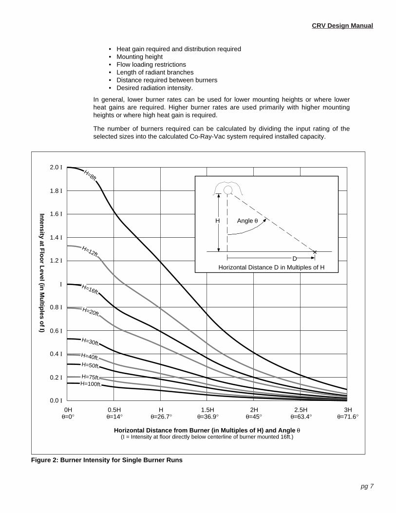
b. Radiant Height Adjustment Factor
As discussed above, the installed capacity of radiant heating systems is typically reducedas compared to the calculated heat loss due to the radiant effects associated with a prop-erly designed radiant heating system. The ability of a radiant system to provide theadvantages of these radiant effects rests largely with the ability of this system to establisha reserve heat capacity in the floor. Without this reserve capacity, radiant comfort cannotbe achieved. (The exception is in station heating/spot heating applications where suffi-ciently high levels of direct radiation are received from the heater.) The height adjustmentfactor is a means to insure adequate floor level radiant intensity to “charge” the floor heatreservoir. Figures 2 and 3 illustrate the relationship of floor level intensity to height for sin-gle and multiple (overlapping) Co-Ray-Vac burner runs.
Additionally, higher mounting heights for radiant heating appliances increase the proba-bil ity for direct radiant energy loss due to exposure of longer wall surfaces.
CRV Design Manual
pg 6
Proportionately larger wall surfaces also remove energy from the floor to a larger degree,decreasing the heat reservoir.
The increased input capacity recommended by a height adjustment factor is not extrane-ous as compared to the heat loss calculation. Rather, it is a realization that in order tomaintain radiant comfort conditions (and the economic benefits) a minimum radiant levelmust be maintained at the floor.
It is recommended that an adjustment to the heat loss of 1% per foot for mountingheights above 20 feet, be added up to 50-60ft.. Above this height, additional correctionoverstates the BTU requirement as determined by the heat loss.
Example 1
Example 2
Note in example 2, if equipment had been conventionally sized based on thermal outputonly, a nearly identical input requirement would result. For mounting heights above 50-60ft., no further correction is generally necessary if the floor level radiant intensityis sufficient to establish a reserve capacity (hence radiant comfort), and the heatloss requirement is satisfied based on thermal output.
Due to the complexity of installations with mounting heights over 50-60 ft., it is advisableto contact the factory for further information regarding the specific application.
c. Selecting the Burners
The number of burners and firing rate for each must be specified in the design layout. Inaddition, an end vent plate must be provided for each end burner to match its firing rate.The following factors should be considered when selecting burner rate:
Given a building with a calculated heat loss of 500,000, what is the installed capaci-ty required of a Co-Ray-Vac system mounted at 60 ft.?
Installed Capacity = Heat Loss x Radiant Adjustment x Height Adjustment
For Co-Ray-Vac systems, a 0.80 radiant adjustment factor is used.The height adjustment is 1% per foot over 20 feet, or 1.40.
∴ Installed Capacity = 500,000 BTU/Hr x 0.80 x 1.40 = 560,000 BTU/Hr.
Given a building with a calculated heat loss of 350,000, what is the installed capaci-ty required of a Co-Ray-Vac system mounted at 30 ft.?
Installed Capacity = Heat Loss x Radiant Adjustment x Height Adjustment
For Co-Ray-Vac systems, a 0.80 radiant adjustment factor is used.The height adjustment is 1% per foot over 20 feet, or 1.10.
∴ Installed Capacity = 350,000 BTU/Hr x 0.80 x 1.10 = 308,000 BTU/Hr.
CRV Design Manual
pg 7
Horizontal Distance from Burner (in Multiples of H) and Angle θ(I = Intensity at floor directly below centerline of burner mounted 16ft.)
Inten
sity at Flo
or L
evel (in M
ultip
les of I)
H=16ft.
H=8ft.
H=20ft.
H=40ft.H=50ft.
H=75ft.
H=12ft.
H=100ft.
H=30ft.
0Hθ=0°
0.5Hθ=14°
Hθ=26.7°
1.5Hθ=36.9°
2Hθ=45°
2.5Hθ=63.4°
3Hθ=71.6°
0.0 I
0.2 I
0.4 I
0.6 I
0.8 I
I
1.2 I
1.4 I
1.6 I
1.8 I
2.0 I
H
D
Angle θ
Horizontal Distance D in Multiples of H
Figure 2: Burner Intensity for Single Burner Runs
• Heat gain required and distribution required• Mounting height• Flow loading restrictions• Length of radiant branches• Distance required between burners• Desired radiation intensity.
In general, lower burner rates can be used for lower mounting heights or where lowerheat gains are required. Higher burner rates are used primarily with higher mountingheights or where high heat gain is required.
The number of burners required can be calculated by dividing the input rating of theselected sizes into the calculated Co-Ray-Vac system required installed capacity.
CRV Design Manual
pg 8
Distance Between Burners (in Multiples of H)(I = Intensity at floor directly below centerline of single burner run mounted 16ft.)
Inten
sity at Flo
or L
evel (in M
ultip
les of I)
H=8ft.
H=12ft.
H=50ft.H=75ft.H=100ft.
H=16ft.
H=20ft.
H=30ft.H=40ft.
0.5H H 1.5H 2H 2.5H 3H
0 I
2 I
4 I
6 I
8 I
10 I
12 I
14 I
16 I
18 I
20 I
0.25H 0.75H
H
DHorizontal Distance D in Multiples of H
D
AdditionalRows
AdditionalRows
Figure 3: Burner Intensity for Multiple Burner Runs
Figure 3 Notes:
• This graph assumes 100% of the radiant output will be allocated to a floor area as defined by a120° pattern width.
• The values shown include the overlap and are minimum values with at least two rows of burnerson either side. The values of intensities are less between all other rows.
• With spacing of 3H between rows, the added intensity from adjacent rows is less than 5%.
4. Clearances to Combustibles
Table 1: Minimum Clearances to CombustiblesAll clearances measured in inches from tube surface.
Reflector Type Position B-2,4,6,8 B-9 B-10,12,12A B-12*,12A*Standard Reflector, any location Below 48 40 60 48
Above 4 4 4 4Side 20 20 36 24
One Side Extension Below 56 46 60 54Above 4 4 4 4
Side w/ Ext. 12 12 12 12Side w/o Ext. 20 24 42 34
Two Side Extensions Below 56 46 60 54Above 4 4 4 4Side 12 12 12 12
Standard Reflector, downstream Below 18 - 24 -(20 ft downstream for CRV 2,4,6,8) Above 4 - 4 -(30 ft. downstream for CRV 10,12) Side 10 - 18 -
* For End Burner position only
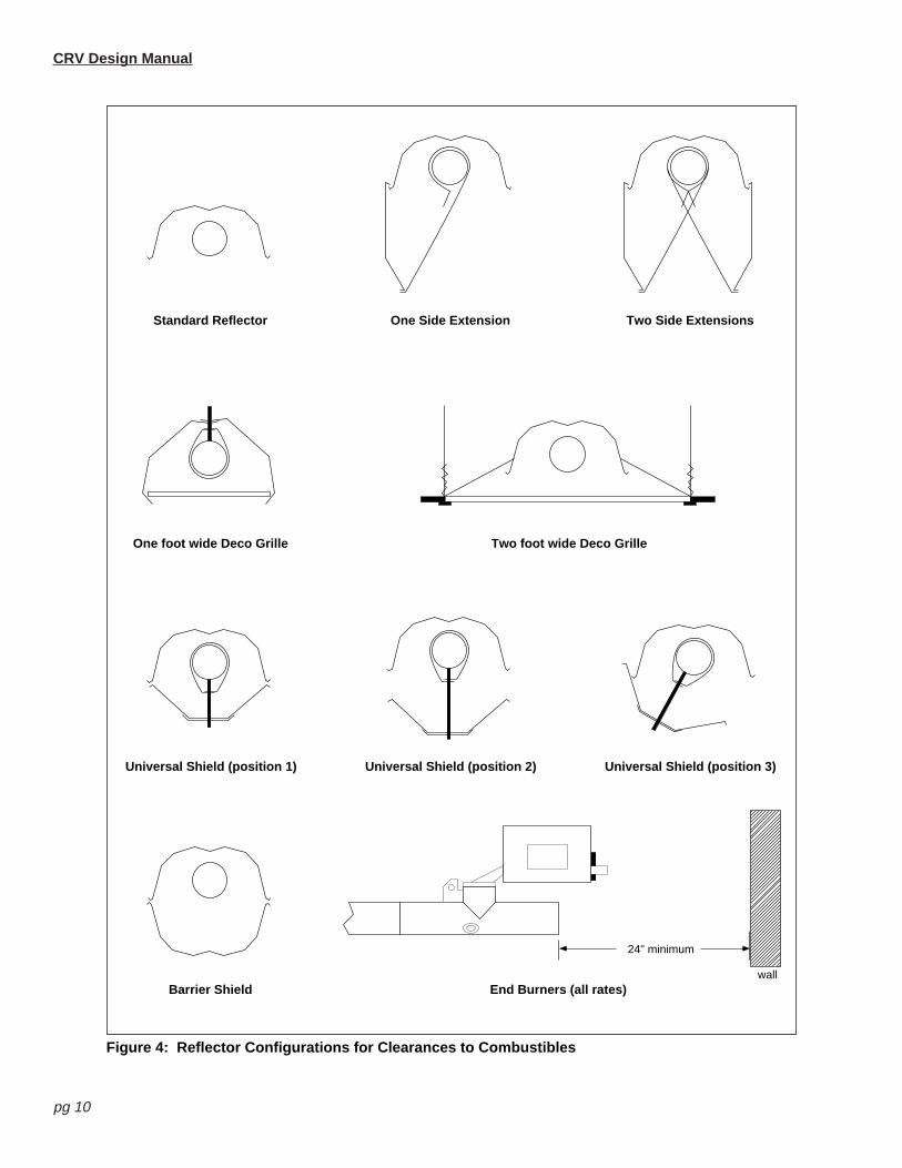
For a schematic view of reflector configurations, see Figure 4.
CRV Design Manual
pg 9
WARNING
FIRE OR EXPLOSION HAZARD
In all situations clearances to combustibles must be maintained. Failure to observe clearances to com-bustibles may result in property damage, severe injury, or death.
Minimum clearances must be maintained from vehicles parked below the heater. Signs should be posted instorage areas to specify maximum stacking height to maintain required clearances to combustibles. Cautionshould be used when running the system near combustible materials such as wood, paper, rubber, etc.
CRV Design Manual
pg 10
Standard Reflector One Side Extension Two Side Extensions
One foot wide Deco Grille Two foot wide Deco Grille
Figure 4: Reflector Configurations for Clearances to Combustibles
CRV Design Manual
pg 11
5. Flow Loading
The patented Co-Ray-Vac burner system allows a number of burners to be installed inseries, in the same radiant tube, resulting in long, continuous radiant emitting surface togive even heat distribution within the building.
To enable the burners to be correctly located within the tube, to maintain system operat-ing vacuum and obtain design flue gas temperatures at the vacuum pump, the designlayout is based on a simplified flow principle using a “flow unit.” Figure 5 details examplecalculations of flow units for various CRV system configurations.
The flow unit is defined as the amount of fuel/air mixture for a heat input of 10,000BTU/Hr. This corresponds to a flow rate of 1.83 cfm at 65-70°F.
For the purpose of design, flow units are considered to enter the Co-Ray-Vac system inone of two ways:
• Through the burner.• Through the end vent plate.
Flow units exit the system as spent products of combustion via the vacuum pump.
Table 2 lists the flow unit values associated with each burner firing rate, its associatedend vent, and minimum flow unit requirement entering a combustion chamber. Table 2also summarizes design and flow loading parameters for Co-Ray-Vac systems.
The purpose of the end vent air is to provide that part of the burner inlet flow required todilute the hot combustion gases at the burner, thereby promoting uniform heating of thetube while avoiding excessive heating of the combustion chamber.
For the end burner, the burner inlet flow consists entirely of the end vent air. For all otherburners, the burner inlet flow consists of the total of the end vent air plus the combustiongases from all upstream burners.
The requirement for minimum burner inlet flow is met if the total flow units entering thecombustion chamber meets or exceeds the minimum as shown in Table 2.
a. Radiant Branch Flow
The flow in a radiant branch consists of the end vent flow units plus the flow units of com-bustion air from all burners.
The limiting factor for maximum flow in the radiant section has been determined experi-mentally in terms of the maximum burner inlet flow units that can be tolerated withoutdegradation of combustion characteristics at the last downstream burner. Also, if morethan the maximum number of burners are installed per radiant branch, the vacuum lossacross the additional burners will increase appreciably.
This maximum flow in the radiant branch can be expressed for each burner firing rate byeither a maximum number of burners per branch or the corresponding maximum numberof flow units. Refer to Table 2.
* CRV B-9 burner requires first downstream tube to be aluminized heat-treated.
Installed Altitude Maximum Flow Units
(ft. above sea level) EP-100 EP-200
0ft - 2000ft. 66 110
2001 ft. - 3000 ft. 63 105
3001 ft. - 4000 ft. 60 100
4001 ft. - 5000 ft. 57 95
5001 ft. - 6000 ft. 54 90
6001 ft - 7000 ft. 51 84
7001 ft. - 8000 ft. 48 80
8001 ft. - 9000 ft. 45 75
Table 3: Vacuum Pump Capacity
Note: Do not use the EP-100 pump withtailpipe longer than 1.7 ft./Flow Unit.
CRV Design Manual
pg 13
b. Tailpipe Flow
Excessive flow loading in a single section of tailpipe can cause low vacuum and lowereffective pump capacity if care is not taken to observe the necessary design requirements.
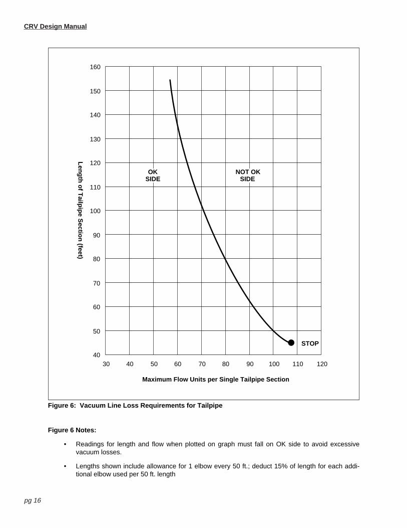
It is important to check the length of tailpipe for each radiant branch, and verify it is within±5% of the recommended length. If the proper end vent vacuum is to be maintained, thelength of tailpipe must not be excessive for the flow units being carried by that section oftailpipe. Refer to Figure 6 to determine adherence to vacuum line loss requirements.
c. Vacuum Pump Capacity
The flow unit capacity of the vacuum pump is indicated in Table 3 as a function ofinstalled altitude. When the CRV system is designed in accordance with this set ofinstructions and is in proper operating condition, a vacuum from 2-3" w.c. will be obtain-able at each end vent (i.e. at all burners.)
There are a number of critical design requirements which, if not met, will reduce the vacu-um obtainable and thereby the effective flow capacity of the vacuum pump. Theseinclude:
• Minimum Length of Tailpipe—if less than the minimum length of tailpipe is pro-vided per radiant branch, there will be insufficient cooling of the combustiongases and improper operation of the vacuum pump.
• Line Loss Check for Tailpipe is applicable to sections of tailpipe which arecommon to two or more radiant branches (i.e. shared lengths). See Figure 6.
• Excessive back pressure on discharge line of vacuum pump as caused by par-tial blockage or too much flow for length.
• Air leaks in the system as caused by poor installation, missing view port win-dows in combustion chambers, leaky burner gaskets, missing or improperlyinstalled end vent plates, poor joints at couplings, obstruction inside the pipe, orincorrectly set dampers.
• More than maximum number of burners or flow units per radiant branch.
• Excessive number of elbow or tee fittings which increases head loss.
If the distance required for the tailpipe to reach the pump position of the system is greaterthan allowed, then there are some alternatives:
1. Use separate branches of reduced flow units for half the distance and then teetogether for the balance of the run.
2. Use separate branches from the pump, each with less flow units. Then eachbranch could be longer as required.
CRV Design Manual
pg 14
Key to Symbols
End Vent(number is flow units)
CRV Burner(number is flow units)
Check Point for Flow(number is flow units)
Damper Coupling
Transition from Radiant to Tailpipe
Radiant Pipe(number is length in feet)
Tailpipe(number is length in feet)
Vacuum Pump(number is model number)
Figure 5a: CRV System with One Branch(3 CRV B-8 Burners in series, minimum radiant pipe, no elbows, sea level)
8 8 820 28 36 4425 ft. 25 ft. 70 ft.
• From Table 2, minimum radiant tube length for B-8 burners is 25 ft.• From Table 3, at sea level EP-100 vacuum pump can safely handle 44 flow units.• Maximum tailpipe length for EP-100 pump is 1.7 ft. per flow unit
(1.7 ft. x 44 flow units = 74.8 ft.). Round 74.8 ft. down to 70 ft..• From Figure 6, 44 flow units are allowed in 70 ft. of shared tailpipe.
EP100
Figure 5b: CRV System with Two Uneven Branches(3 CRV B-10 Burners in branch 1, 2 CRV B-12 Burners and 1 CRV B-10 Burner in branch 2,recommended radiant pipe, recommended tailpipe, 2 elbows in radiant section, sea level)
25 ft.
10 10 1020 30 40 5040 ft. 40 ft. 40 ft.
12 12 1020 32 44 5450 ft. 50 ft. 40 ft. 84 ft.
EP200
• From Table 2, recommended radiant tube length for B-10 burners is 40 ft.; for B-12 burners it is 50 ft..• Recommended tailpipe length is 2 ft. per flow unit (2 ft. x 104 flow units = 208 ft.)• From Table 3, at sea level EP-200 vacuum pump is rated to handle 104 flow units.• If system were to be installed above 3000 ft., this configuration would exceed the EP-200 capacity
and would thus have to be redesigned.• According to Table 2, the maximum number of flow units in a mixed branch is 54. Therefore, if
branch 2 had 3 B-12 burners it would exceed the flow unit limit.• From Figure 6, 104 flow units allowed in 40 ft. w/ 1 elbow per 50 ft. of tailpipe.
84 ft.
40 ft.
d. Flow Unit Calculations
CRV Design Manual
pg 15
Figure 5c: CRV “SC” System with Equal Branches and Mixed Tailpipe(2 CRV B-9 Burners in series in 2 branches, minimum radiant pipe, recommended tailpipe,4 elbows in radiant section, 4000 ft. altitude)
915 24
• From Table 2, minimum radiant tube length for B-9 burners is 20 ft.• To achieve CRV “SC”short clearances, the first 10 ft. section of downstream radiant tube from
each B-9 burner must be aluminized.• Recommended tailpipe length is 2 ft. per flow unit. The two individual 33 ft. sections of tailpipe
each handle 33 flow units from their respective branches. The combined section must handlethe resulting 66 flow units. Therefore, the final section must be 132 ft. long (66 flow units x 2 ft.
per flow unit.)• From Table 2, at 4000 ft the EP-100 vacuum pump can handle 60 flow units, therefore, the EP-
• From Table 2, minimum radiant tube length for B-12 burners is 35 ft.• Minimum tailpipe length is 1.2 ft. per flow unit (1.2 ft. x 32 flow units = 38.4 ft.). For convenience,
round this number to the nearest 10 ft. section: 38.4 ft ≈ 40 ft.• From Table 3, at sea level EP-100 vacuum pump can safely handle 64 flow units.• The end burner only B-12 system qualifies for the shorter clearances in column 4 of Table 3:
Minimum Clearances to Combustibles on pg 9. If the two burners were in series in one branch, theclearances in column 3 would apply.
9 15
33
24
33
9 9EP200
20 ft. 20 ft.
20 ft.20 ft. 33 ft. 33 ft.
66 ft.
12 203235 ft.40 ft. 40 ft.EP100
CRV Design Manual
pg 16
160
150
140
130
120
110
100
90
80
70
60
50
4030 40 50 60 70 80 90 100 110
Len
gth
of T
ailpip
e Sectio
n (feet)
Maximum Flow Units per Single Tailpipe Section
OKSIDE
NOT OKSIDE
120
STOP
Figure 6: Vacuum Line Loss Requirements for Tailpipe
Figure 6 Notes:
• Readings for length and flow when plotted on graph must fall on OK side to avoid excessivevacuum losses.
• Lengths shown include allowance for 1 elbow every 50 ft.; deduct 15% of length for each addi-tional elbow used per 50 ft. length
CRV Design Manual
pg 17
6. Heat Exchanger Surface
The main purpose of the tailpipe and the radiant pipe is to provide sufficient heatexchanger surface to transfer the heat from the flue gases to the tube wall where it canbe released from the outside surface of the tube as useful heat. Radiant pipe is definedas the tubing between burners firing in a radiant branch, plus the radiant tubing immedi-ately following the last downstream burner. Tailpipe is defined as all tubing between theradiant pipe and the vacuum pump.
Most of the radiant heat supplied by each burner is released from the outside surface ofthe radiant pipe; the balance is released by the tailpipe. The placement of radiant pipe tocorrespond to areas of major heat loss is the key to providing uniform comfort levels. Theuse of adequate tailpipe is the key to high combustion efficiency and proper operation ofthe vacuum pump.
a. Radiant Pipe
The considerations in selection the length of radiant pipe include the following:
Minimum: This provides for the highest level of average intensity per foot of radi-ant pipe and good uniformity between burners. This requires more tailpipe to main-tain operating efficiency and pump capacity.
Maximum: This provides the lowest average value of intensity per foot of radiantpipe, and consequently the largest span between burners. The intensity will bereduced slightly for the last 5-10 ft. of radiant pipe before the next burner.
The length of radiant pipe required for burners varies according to the firing rates. Also,consideration has been give to usage of a standard 10 ft. length or lengths that can becut from same without waste. Refer to Table 2.
When positioning radiant pipe to give the required radiant distribution it is important toconsider:
• Clearances to adjacent combustible materials.• Lighting equipment.
b. Tailpipe
The considerations in selecting the amount of tailpipe include the following:
Minimum: This is the minimum length of tailpipe to cool the flue gases sufficiently forproper operation of the vacuum pump. Excessive temperatures at the inlet to thepump will reduce the effective flow capacity and the vacuum obtainable in the system.
Maximum: The maximum limit established for the amount of tailpipe that can beused is defined in Table 2. This permits the use of an extended connecting length oftailpipe if a branch of burners is remotely located which would otherwise require aseparate vacuum pump. It should be noted that if there are traces of corrosive conta-minants in the combustion air, much of this longer section of tailpipe will be exposedto the corrosive conditions due to low temperature in the end of the tailpipe.
In regard to the length of tailpipe required per flow unit, there is a trade-off betweenlength of radiant pipe and length of tailpipe. Consequently, the recommendations fortailpipe are stated below:
Tailpipe Length (with recommended or maximum length of radiant pipe)Minimum 1.2 ft./Flow UnitMaximum 2.5 ft./Flow Unit
CRV Design Manual
pg 18
Tailpipe Length (with minimum length of radiant pipe)Minimum 2.0 ft./Flow UnitMaximum 3.0 ft./Flow Unit
Note: The maximum tailpipe for the model EP-100 pump is 1.7 ft./Flow Unit.Operation of the pump in excess of 1.7 ft./Flow Unit will cause permanentfailure of the assembly.
Figure 7 relates the effect on system thermal efficiency of variations in radiant andtailpipe lengths. The chart was created based on test data obtained in accordance withmethodology developed by the National Bureau of Standards (NBSIR 80-2110) and rec-ommendations on flue loss calculation contained in ANSI Z83.6 (latest edition). Actualinstallation variables (gas BTU content, air temperature and operation cycle, etc.) mayeffect efficiencies (positively or negatively). As such, Figure 7 is presented as a guide tothe designer for information only.
Note: When accounting for the required tailpipe lengths during the design process,it is important to verify that the tailpipe for each branch is at least equal tothe specified minimum.
For radiant branches which are served by shared tailpipe section, the shared sectionscan be allocated to either branch with any distribution of length. The objective is to allo-cate the shared section in a way which permits the minimum length requirement to bemet for all radiant branches served by that shared section. The prime consideration isthat each foot of shared section can be counted only once.
Len
gth
of T
ailpip
e per F
low
Un
it (feet)
Steady State Thermal Efficiency (%)
1.0
1.5
2.0
2.5
3.0
83% 84% 85% 86% 87% 88% 89% 90%
Min
imum
Rad
iant
Pip
e
Nom
inal
Rad
iant
Pip
e
Max
imum
Rad
iant
Pip
e
Figure 7: Tube Length vs. Efficiency
Figure 7 Note: Thermal efficiency values shown do not include the contribution due to condensing con-ditions when operating in cyclic fashion. To estimate cyclic efficiencies add 2-3% to thevalues obtained from the graph
CRV Design Manual
pg 19
7. Selecting a Control System
All Co-Ray-Vac systems may employ a solid state electronic control panel. In addition toproviding system management, the control panel can also be used to provide individualzone temperature control for up to four zones. The control panel is required on large sys-tems (as defined by electrical requirements) and optional on small systems. Small sys-tems can use a thermostat and relay, which can also provide zone temperature controlfor up to two different areas.
a. Control Methods
There are three different ways to control a Co-Ray-Vac system:
1) Electronic Control Panel (P/N 02770001)With a single 20 amp, 120V supply can operate the vacuum pump and all burnerswith in a system with up to four zones. Required for use with SmartSet EnergyManagement System
2) SPDT Transformer Relay (P/N 90417600)With a single 20 amp, 120V supply can operate the vacuum pump and up to 9 burn-ers in a system with only one zone.
3) DPDT Transformer Relay (P/N 90436300)With a single 20 amp, 120V supply can operate the vacuum pump and up to 9 burn-ers in a system with up to two zones.
Low-voltage thermostats (24V) should be used. Thermostats that draw power from thesystem must not be used with the control panel, since the control panel provides only 5Vof power to each thermostat.
A Vacuum Proving Switch (P/N 90430600) is required to interlock vacuum pump opera-tion. The EP-200 pump includes an integral Centrifugal Motor Interlock which may beused in addition to the vacuum proving switch.
A Vacuum Proving Switch (P/N 90434500) is also required on the inlet duct of a non-pressurized air supply. For pressurized outside air supplies, the outside air blower motorhas a Motor Interlock that must be used. These controls must be wired in series with theVacuum Pump Interlock/Proving Switch.
When using an outside air blower either with a control panel or relay transformer, a sepa-rate Load Relay Package (P/N 05023000) is required. The control for the relay must bewired in parallel with the vacuum pump. The power must be supplied by a separate20amp, 120V power supply.
b. SmartSet Energy Management System
Systems requiring energy management should employ the optional Smart Set EnergyManagement System (P/N02770101). The SmartSet is a microprocessor-based controlsystem that installs directly on the Electronic Control Panel.
SmartSet Specification:
• System continually monitors the demand for heat and automatically regulates theburner firing cycles accordingly to provide for maximum comfort and fuel efficiency.
• System includes a 365 day time clock providing for automatic holiday program-ming and night set-back with four change-of-state points per day per zone.
CRV Design Manual
pg 20
• Emergency battery backup is included to prevent program loss on power failure.
• System is capable of operating up to 4 independent heating zones.
• Programming is easily accomplished via an LCD/Keypad interface included asstandard.
• Service and installation of the SmartSet is accomplished via easy “plug-in”access, and shall not prevent system from operating in a standard fashion.
8. Air Supply System
An air supply free of dust and corrosive contaminants is essential for proper operationand best life expectancy with any heating system. With Co-Ray-Vac there are two alter-natives available to the designer for providing the air supply. These are:
• Individual filter for each burner. A single filter door is standard for each burner.
• Outside air system to duct air from an uncontaminated source. A single filter foreach burner is used plus outside air supply to provide both combustion and endvent air. It must be determined that outside air is not contaminated by exhaustfrom the same building and/or neighboring buildings.
The first alternative above is usable when the dust load is not excessive and there is nousage of corrosive contaminants such as solvents or vapors inside the building or inclose proximity to the building. Vapors in close proximity could include exhaust air from anearby factory such as a chemical plant, a dry cleaning establishment, etc..
The second alternative must be used in all applications where corrosive contaminantsmay be present in the air in trace amounts (few parts per million) for several days or moreper year during the heating season.
It is important for designers and owners of heating systems to note that the presence oftraces of corrosive contaminants in the combustion air supply will greatly accelerate therate of corrosion on heat exchanger surfaces and will shorten the useful life of the heatingsystem accordingly. This is true regardless of whether the heating system is Co-Ray-Vac,other infrared systems or conventional gas or oil-fired equipment such as unit heaters,central boiler plant, etc..
With Co-Ray-Vac it is practical to provide an air supply system for filtered combustion airwithout any possibility of upsetting the fuel/air mix as the filter loading increases. With theunique vacuum powered burners, the fuel/air mix remains constant.
It can be expected that the use of an outside air system will reduce but not eliminate thecorrosion.
In a way similar to the Co-Ray-Vac vacuum pump system, the design of the air supply sys-tem also involves considerations of total flow units and acceptable combinations of ductlengths (and diameters) versus flow units carried. In certain circumstances it may be desir-able to introduce an outside air blower to pressurize the system. The small positive pres-sure is desirable and necessary to prevent the system from drawing in contaminated air.
CRV Design Manual
pg 21
Flo
w U
nits
Straight Duct Length (feet)
0 50 100 150 200 2500
20
40
60
80
100
120
140
7"
6"
5"
4"
DUCTDIAMETER
Note: For capacity requirements larger than shown, use 8" duct.
Figure 8: Air Supply System Capacity by Duct Length and Diameter(Based on 0.25" w.c. maximum line loss)
To size each section of pipe proceed as follows:
• Calculate the required flow units at each outlet of the supply system.
• Measure the longest run of pipe from the blower to the most remote outlet. Useonly this distance in Figure 8 (or the next longer distance if the exact distance isnot shown). This is to provide assurance that the pressure drop to the mostremote outlet will not exceed 0.25" w.c. when all outlets are supplied.
• To use Figure 8, find the intersection point on the graph for the appropriate ductlength and number of flow units. The duct size above this intersection point indi-cates what size duct work should be used. Proceed in a similar manner for eachoutlet and each section of duct. For each section of duct, determine the total flowunit capacity supplied by that section.
CRV Design Manual
pg 22
10. Co-Ray-Vac Equipment Specifications
The total heating system supplied shall be design certified by theAmerican Gas Association and this per American National StandardZ83.6 (latest edition).
A. Burner and Burner Controls
1. Burners shall be designed to fire simultaneously in series withoutadverse effects from combustion gases from upstream burners.
2. Burners shall be capable of firing with one of the fuel options as speci-fied on the purchase documents: Natural Gas, or LP.
3. Burners shall be supplied to fire at any one of the input firing rates asspecified:
4. The design of burners supplied shall provide for maintaining a con-stant proportion of fuel gas to filtered combustion air. These conditionsare met for burners in which the pressure of both the fuel gas and thecombustion air are introduced at zero (atmospheric) pressure and theflow of each is established by a vacuum on the downstream side ofthe flow metering orifices.
5. To assure a high degree of fail-safe operation, the design shall pre-clude flow of gas if any or all of the following abnormal conditionsoccur in the non-firing mode:
a. Main valve fails in open position.
b. Vacuum pump motor fails to operate.
c. Power fails.
6. To further assure a high degree of safety, the system will be undernegative pressure at all times during operation to preclude the possi-bility of the escape of combustion gases inside the building.
7. The burner control assembly will always include a zero regulator.
B. Equipment
1. Burner
a. Each burner assembly shall consist of heavy-duty cast-iron burn-er heads, pre-wired gas controls with electronic, three-try directspark ignition and combustion air filters.
2. Vacuum Pump
a. The housing shall be heavy-duty cast-iron. (Or 16 gauge stampedsteel for small systems as defined by vacuum requirements.) Theimpeller shall be cast aluminum alloy dynamically balanced andmounted for direct drive on the motor shaft.
CRV Design Manual
pg 23
b. The vacuum pump shall be acoustically isolated from the systemwith a flexible connector with temperature rating of 350°F mini-mum. The motor in the vacuum pump shall be secured with rubbermounts for acoustical isolation.
c. Vacuum pump motor shall be 115/230V, 60 Hz, 3450 rpm, TENV,with capacitor start, sealed ball bearings and thermal protected.
3. Heat Exchanger
a. Radiant tubing (between burners and 10 - 70 feet downstream oflast burner) shall be of 4" O.D. steel or heat treated aluminizedtubing.
b. The balance of the tubing shall be 4" O.D. steel tubing with aninternal coating of acid-resistant porcelain. (Internal/external coat-ing optional.)
c. All heat exchanger (tubing) connections shall be made with stain-less steel coupling assemblies. Unlined couplings will be used withuncoated tubing or to connect uncoated to coated tubing. Linedcouplings will be used to connect coated to coated tubing.
4. System Control
a. All burners shall be pre-wired with a grounded electrical cord andplug.
b. When specified, provide a solid-state electronic control panel tofacilitate zone temperature control for up to four zones. Smallersystems (as defined by electrical requirements) may be controlledwith a thermostat and relay.
c. Optionally provide the microprocessor-based SmartSet™ energymanagement system to facilitate heat programming and set-backfeatures.
5. Outside Air
a. When specified, in contaminated environments, the system shallbe capable of supplying air from the outside to each burner andend vent for the support of combustion.
C. Special Short Clearances Models
Where specified provide burner configurations capable of reduced clear-ances to combustibles in height-critical applications.
1. CRV “SC”
System shall consist of 1-3 branches with two CRV B-9 burners perbranch. The first section of tubing downstream from each burner shall beheat-treated aluminized. Systems configured this way will be eligible forreduced clearances to combustibles. System is approved for use with 30ft. of tailpipe per branch when maximum radiant pipe is used.
2. CRV 12/12A End Burner Only
System shall consist of 1-4 branches with one CRV 12/12A burner perbranch. Systems configured this way will be eligible for reduced clear-ances to combustibles.