Design Of 210 Mld Sewage Treatment Plant Submitted By: Agraj Tiwari Anurag Rawat Arun Kumar Pradyumn Sharma Ravi Zeem Under the guidence of: Miss Renu Sharma DEPARTMENT OF CIVIL ENGINEERING Allenhouse Institute of Technology, Kanpur Uttar Pradesh Technical University, Lucknow (UP) INDIA A Presentation of project On
DEPARTMENT OF CIVIL ENGINEERINGAllenhouse Institute of Technology, Kanpur
Uttar Pradesh Technical University, Lucknow (UP) INDIA
A Presentation of projectOn
INTRODUCTION Its objective is to produce an environmentally safe fluid waste stream and
a solid waste suitable for disposal or reuse .
The objective of sewage treatment is to produce a disposable effluent without causing harm to the surrounding environment, and prevent pollution.
Sewage is a major carrier of disease (from human wastes) and toxins (from industrial wastes). The safe treatment of sewage is thus crucial to the health of any community. This article focuses on the complex physical and biological treatments used to render sewage both biologically and chemically harmless.
NEED OF PROJECT In recent years, with increasing awareness of sewage system effects on the
environment, technology has advanced with the introduction of reticulated pipe work systems collecting sewage from both domestic and industrial sources, transfer of collected sewerage to a central treatment facility, and state of the art treatment technology to ensure that discharge to streams and disposal of by products wastes do not threaten to environment. Typical residential water usage is from 75 to 100 gallons per person day. Seventy-three percent is connected to a centralized wastewater collection and treatment system, while remaining 27% uses on site.
This project also suit objectives of “Ganga Action Plan” which is excuted by Central Government Of India for decreasing pollution level in holly river Ganga.
We can recycle the wastewater and reuse that recycled water according to their treated values.
IMPORTANCE OF SEWAGE WATER TREATMENT PLANT:-
It is very important to provide some degree of treatment to wastewater before it can be used for agricultural or landscape irrigation or for aquaculture.
The principal objective of sewage treatment is generally to allow human effluents to be disposed of without danger to human health or unacceptable damage to the natural environment.
According to a research, a large number of people die from water born diseases in most of the developing countries. Therefore, it is very important to get the proper treatment of the water for a healthy living.
Water Related Diseases and Their Causes
Bacteria• E. coli• Salmonella typhi• Shigella spp.• Yersinia
Sewage treatment generally involves three stages, mainly are
PRIMARY TREATMENT
SECONDARY TREATMENT
TERTIARY TREATMENT
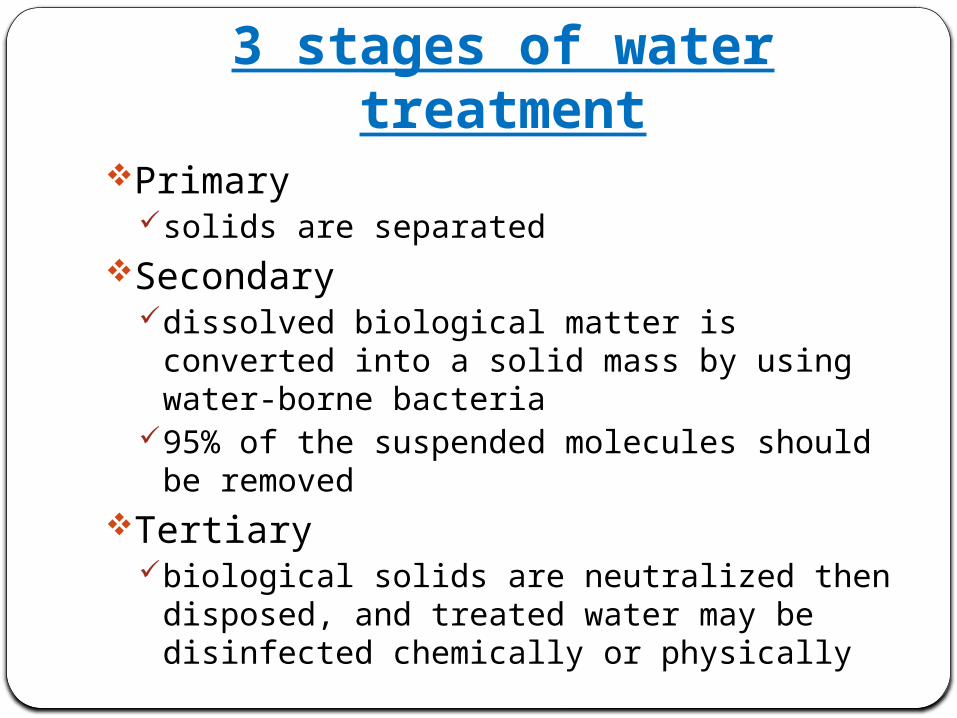
3 stages of water treatmentPrimary
solids are separated Secondary
dissolved biological matter is converted into a solid mass by using water-borne bacteria
95% of the suspended molecules should be removedTertiary
biological solids are neutralized then disposed, and treated water may be disinfected chemically or physically
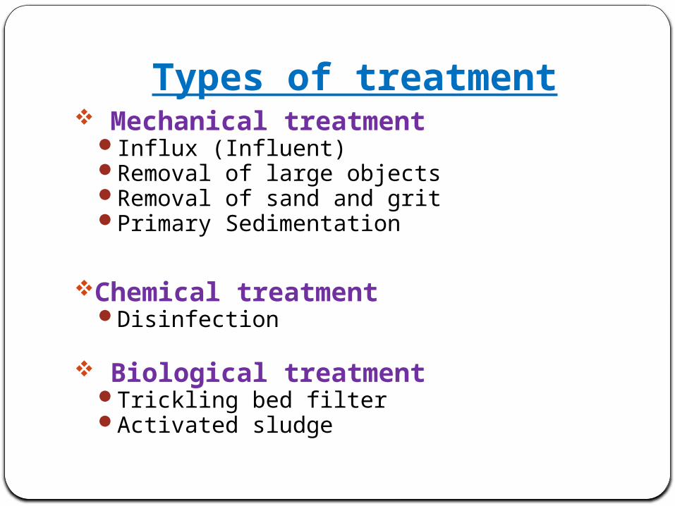
Types of treatment Mechanical treatment
Influx (Influent) Removal of large objects Removal of sand and grit Primary Sedimentation
Chemical treatmentDisinfection
Biological treatmentTrickling bed filterActivated sludge
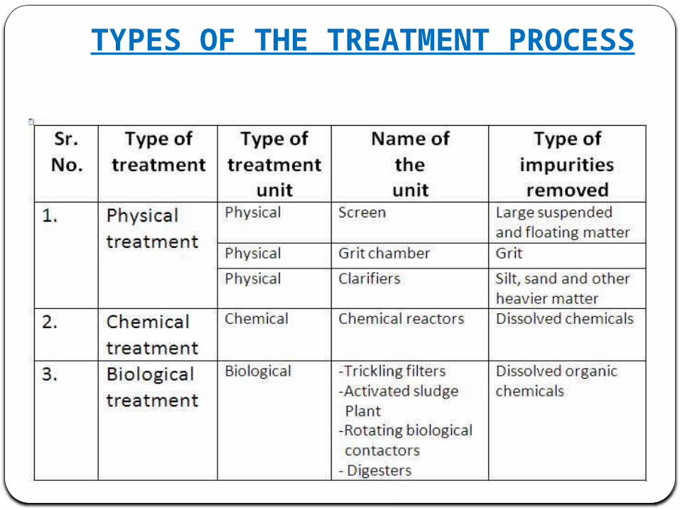
TYPES OF THE TREATMENT PROCESS
PRIMARY TREATMENT
Primary treatment removes materials that can be easily collected from the raw sewage before they damage or clog the pumps and sewage lines of primary treatment clarifiers trash, tree limbs, leaves, branches etc..
The settled and floating materials are removed and the remaining liquid may be discharged or subjected to secondary treatment.
The primary treatment system includes all the units of the preliminary treatment system and the Primary Sedimentation Tank (PST), also known as the primary clarifier. When only these units are provided for treatment it is called primary treatment of wastewater. Fig. shows a schematic diagram of a typical primary treatment system.
PRIMARY TREATMENT
These methods are used in the treatment process
BAR SCREENING
GRIT REMOVAL PROCESS
SEDIMENTAION
CHLORINATION
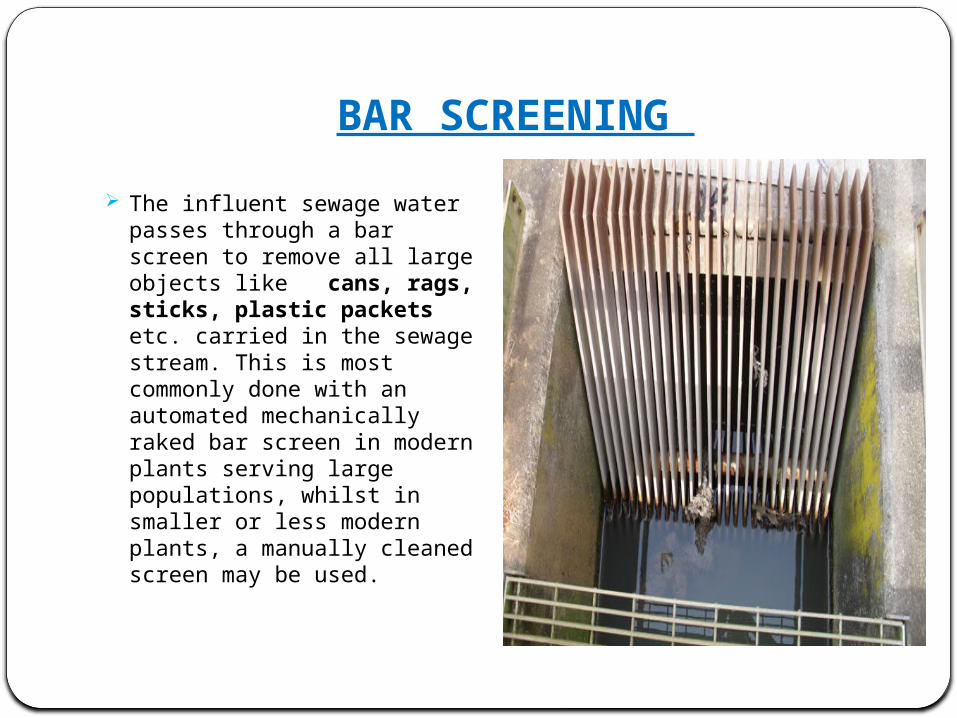
BAR SCREENING The influent sewage water
passes through a bar screen to remove all large objects like cans, rags, sticks, plastic packets etc. carried in the sewage stream. This is most commonly done with an automated mechanically raked bar screen in modern plants serving large populations, whilst in smaller or less modern plants, a manually cleaned screen may be used.
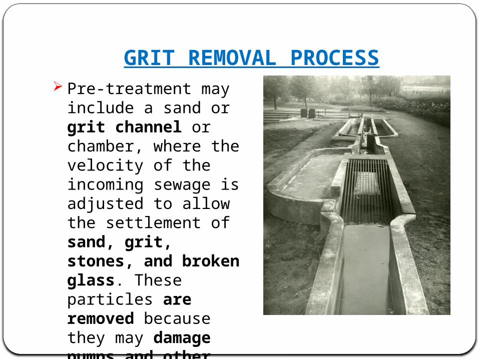
GRIT REMOVAL PROCESS Pre-treatment may include
a sand or grit channel or chamber, where the velocity of the incoming sewage is adjusted to allow the settlement of sand, grit, stones, and broken glass. These particles are removed because they may damage pumps and other equipment.
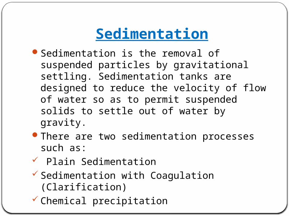
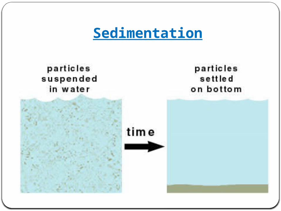
SedimentationSedimentation is the removal of suspended
particles by gravitational settling. Sedimentation tanks are designed to reduce the velocity of flow of water so as to permit suspended solids to settle out of water by gravity.
There are two sedimentation processes such as:
Plain Sedimentation Sedimentation with Coagulation (Clarification) Chemical precipitation
Sedimentation
SECONDARY TREATMENT
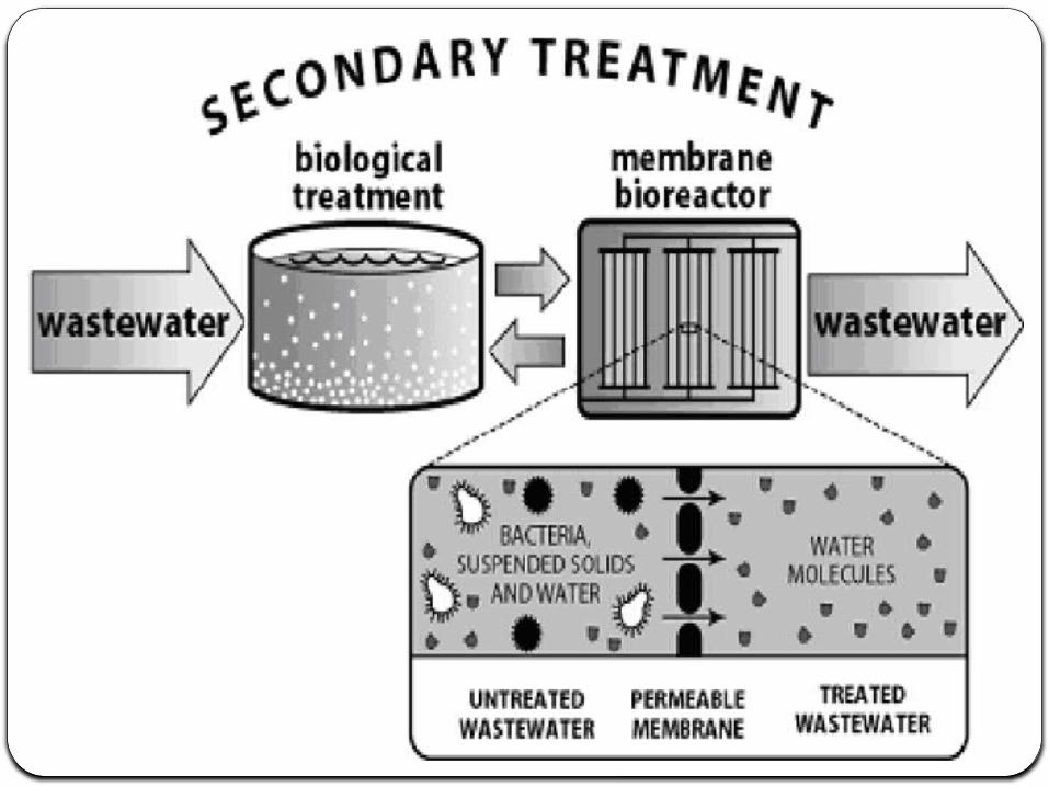
Secondary treatment removes dissolved and suspended biological matter. Secondary treatment is typically performed by indigenous, water-borne micro-organisms in a managed habitat.
Secondary treatment may require a separation process to remove the micro-organisms from the treated water prior to discharge or tertiary treatment.
SECONDARY TREATMENTThere are some treatments used in this method
The UASB reactor is a methanogenic (methane-producing)
UASB is the expanded granular sludge bed (EGSB) digester.
The upward flow combined with the settling action of gravity suspends the blanket with the aid of flocculants.
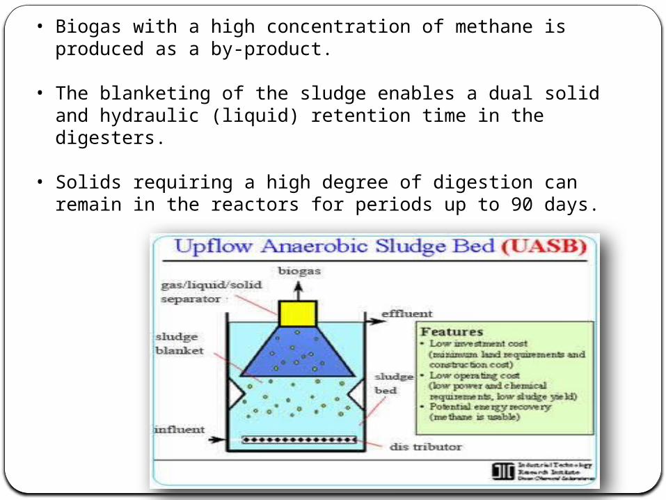
• Biogas with a high concentration of methane is produced as a by-product.
• The blanketing of the sludge enables a dual solid and hydraulic (liquid) retention time in the digesters.
• Solids requiring a high degree of digestion can remain in the reactors for periods up to 90 days.
Material and Construction of UASB Reactors
The modification incorporated in the 14 mld UASB plant at Mirzapur constructed in 1989 over that 5 Mld UASB plant at Kanpur under GAP were in the selection & introduction of Fibre Reinforced Plastic(FRP)(bisphenol resin) rectify corrosion problems and resulting in longer durability.
In other UASBs, further necessary improvements were incorporated, such as, improvement in fixing of FRP feed inlet boxes, Gas Liquid Solids Separator (GLSS), change in design of deflector beam, selection of most appropriate material with respect to durability and costs etc.
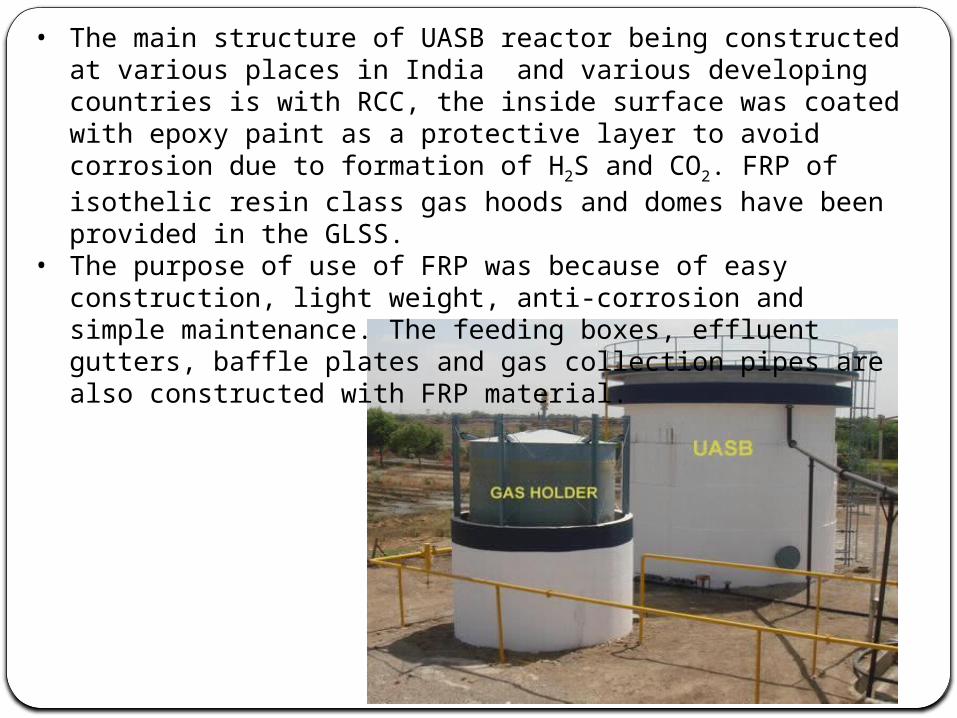
• The main structure of UASB reactor being constructed at various places in India and various developing countries is with RCC, the inside surface was coated with epoxy paint as a protective layer to avoid corrosion due to formation of H2S and CO2. FRP of isothelic resin class gas hoods and domes have been provided in the GLSS.
• The purpose of use of FRP was because of easy construction, light weight, anti-corrosion and simple maintenance. The feeding boxes, effluent gutters, baffle plates and gas collection pipes are also constructed with FRP material.
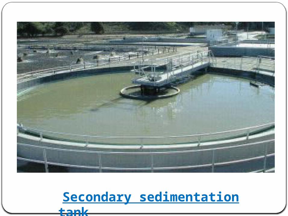
Secondary sedimentation tank
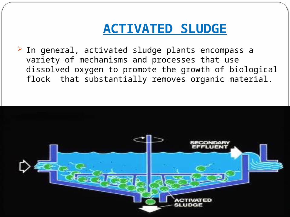
ACTIVATED SLUDGE
In general, activated sludge plants encompass a variety of mechanisms and processes that use dissolved oxygen to promote the growth of biological flock that substantially removes organic material.
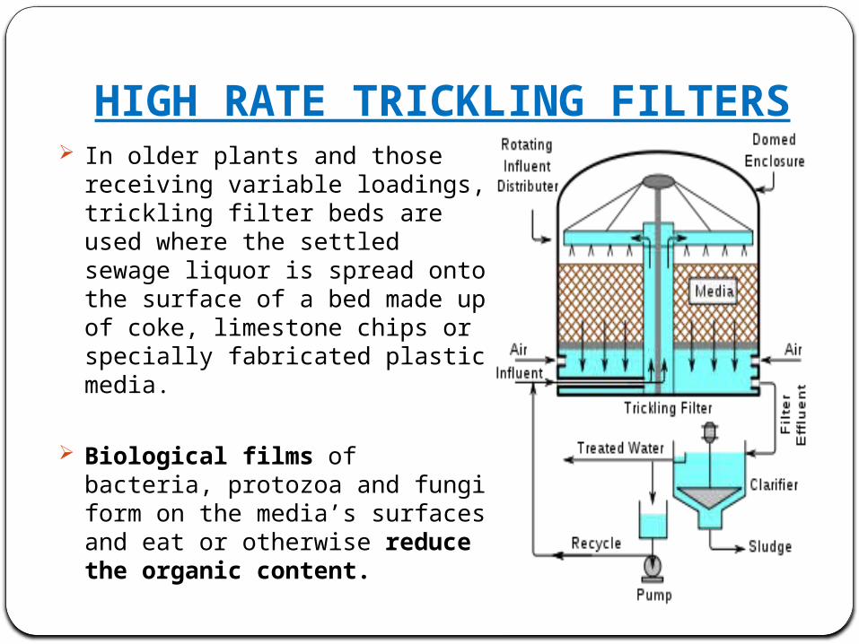
HIGH RATE TRICKLING FILTERS In older plants and those receiving
variable loadings, trickling filter beds are used where the settled sewage liquor is spread onto the surface of a bed made up of coke, limestone chips or specially fabricated plastic media.
Biological films of bacteria, protozoa and fungi form on the media’s surfaces and eat or otherwise reduce the organic content.
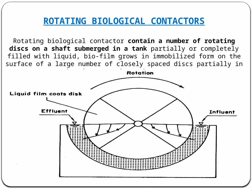
ROTATING BIOLOGICAL CONTACTORS
Rotating biological contactor contain a number of rotating discs on a shaft submerged in a tank partially or completely filled with liquid, bio-film grows in
immobilized form on the surface of a large number of closely spaced discs partially in the air space above the reactor.
TERTIARY TREATMENT
The purpose of tertiary treatment is to provide a final treatment stage to raise the effluent quality before it is discharged to the receiving environment (sea, river, lake, ground, etc.). More than one tertiary treatment process may be used at any treatment plant.
If disinfection is practiced, it is always the final process. It is also called "effluent polishing."
TERTIARY TREATMENTThere are few treatment process done in this method
FILTERATIONSLUDGE DRYING BEDCHLORINATION
FILTRATION
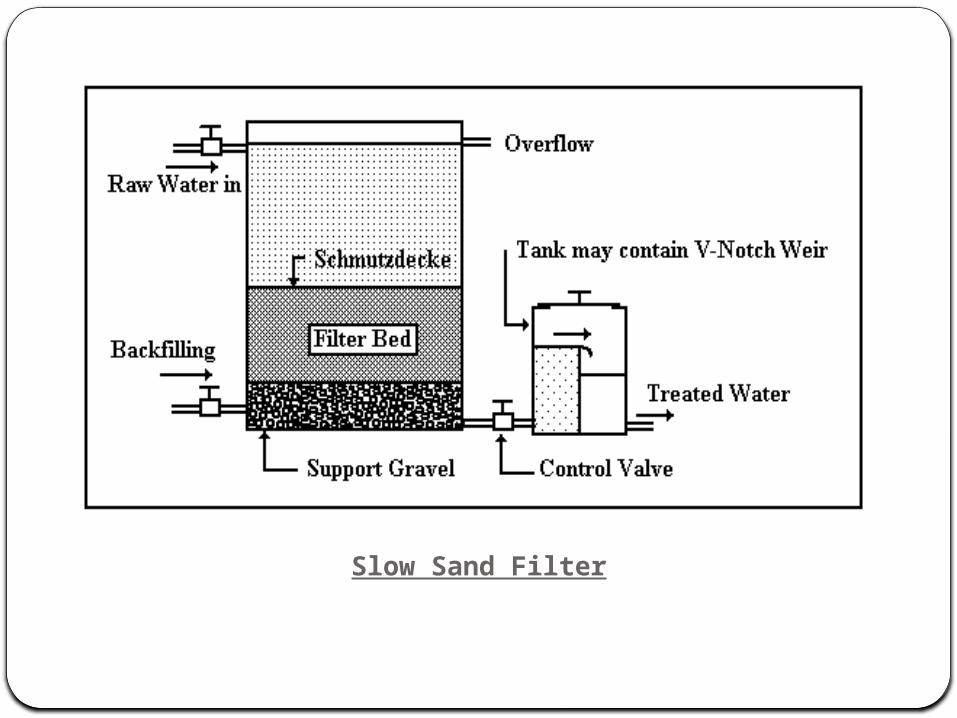
When water flows through a porous ,or open-textured, medium such as sand, some of the suspended and colloidal impurities in water are left behind in the pores or openings or upon the medium itself. This process of separating impurities is called filtration.
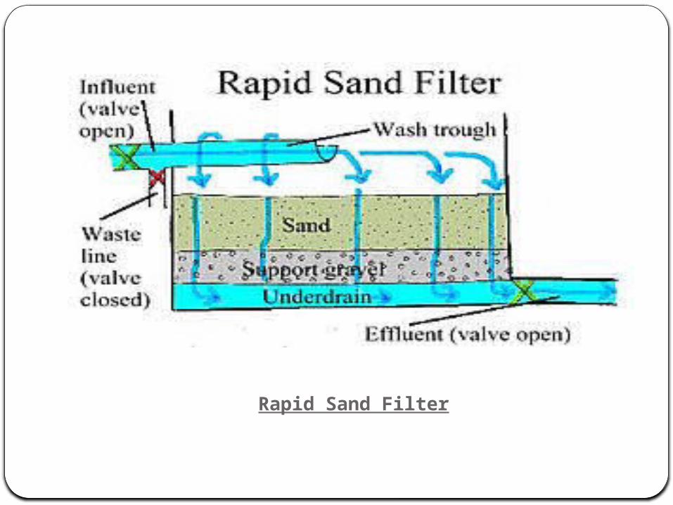
In filtration process, generally we have to types of filters a. Slow sand filter b. Rapid sand filter
Sand filtration removes much of the residual suspended matter. Filtration over activated carbon, also called carbon adsorption, removes residual toxins.
Slow Sand Filter
Rapid Sand Filter
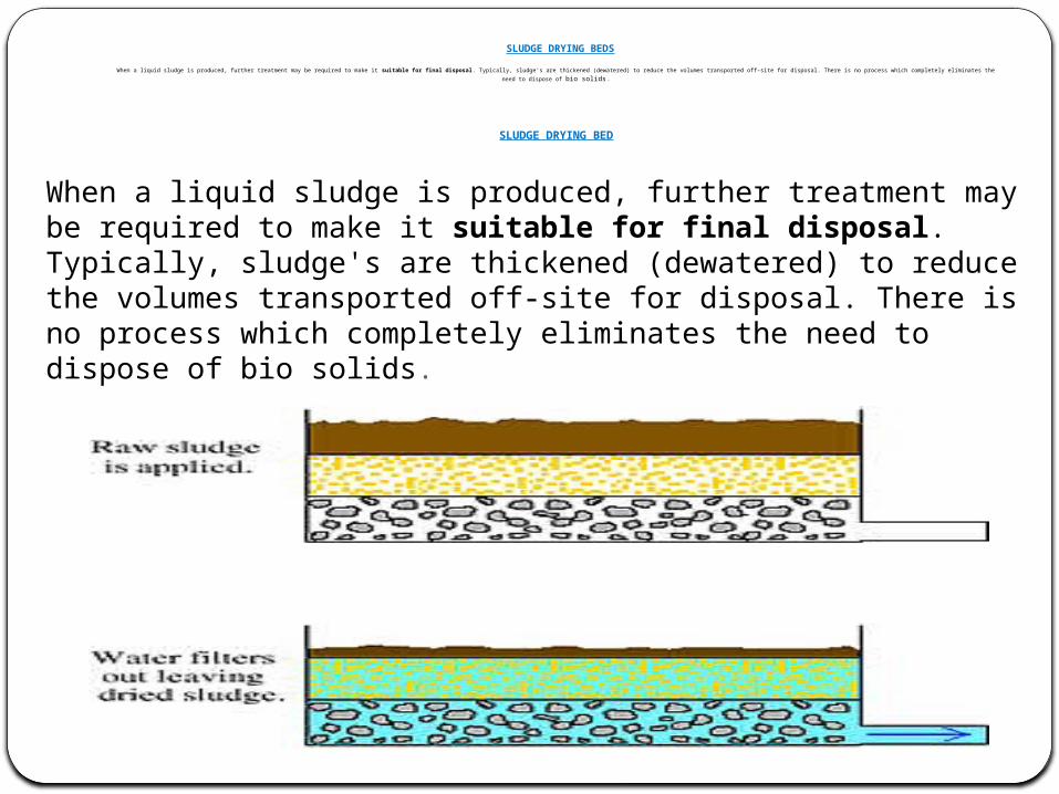
SLUDGE DRYING BEDS
When a liquid sludge is produced, further treatment may be required to make it suitable for final disposal. Typically, sludge's are thickened (dewatered) to reduce the volumes transported off-site for disposal. There is no process which completely eliminates the need to dispose of bio solids.
SLUDGE DRYING BED
When a liquid sludge is produced, further treatment may be required to make it suitable for final disposal. Typically, sludge's are thickened (dewatered) to reduce the volumes transported off-site for disposal. There is no process which completely eliminates the need to dispose of bio solids.
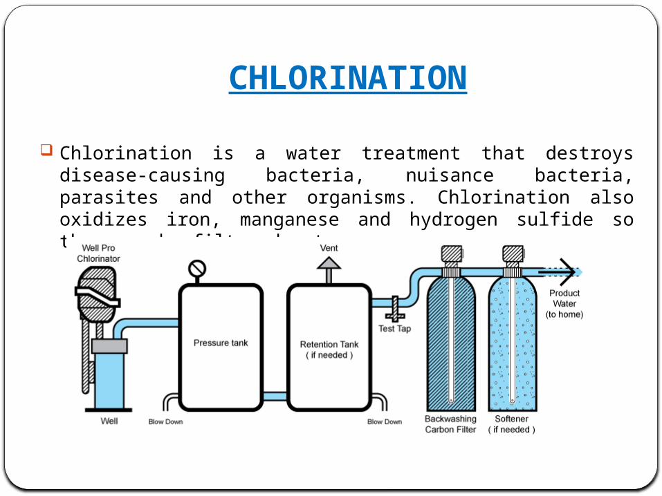
CHLORINATION
Chlorination is a water treatment that destroys disease-causing bacteria, nuisance bacteria, parasites and other organisms. Chlorination also oxidizes iron, manganese and hydrogen sulfide so they can be filtered out.