This article was downloaded by: [University of Windsor] On: 17 July 2014, At: 02:28 Publisher: Taylor & Francis Informa Ltd Registered in England and Wales Registered Number: 1072954 Registered office: Mortimer House, 37-41 Mortimer Street, London W1T 3JH, UK Heat Transfer Engineering Publication details, including instructions for authors and subscription information: http://www.tandfonline.com/loi/uhte20 Design of a Compact Ceramic High-Temperature Heat Exchanger and Chemical Decomposer for Hydrogen Production Valery Ponyavin a , Yitung Chen b , Taha Mohamed c , Mohamed Trabia b , Anthony E. Hechanova d & Merrill Wilson e a Gas Turbine Accessories Design and Development, GE Energy , Greenville , South Carolina , USA b Department of Mechanical Engineering , University of Nevada , Las Vegas , Nevada , USA c Piping Mechanical Engineer , Houston , Texas , USA d Harry Reid Center for Environmental Studies, University of Nevada , Las Vegas , Nevada , USA e Ceramatec, Inc. , Salt Lake City , Utah , USA Accepted author version posted online: 11 Jan 2012.Published online: 13 Mar 2012. To cite this article: Valery Ponyavin , Yitung Chen , Taha Mohamed , Mohamed Trabia , Anthony E. Hechanova & Merrill Wilson (2012) Design of a Compact Ceramic High-Temperature Heat Exchanger and Chemical Decomposer for Hydrogen Production, Heat Transfer Engineering, 33:10, 853-870, DOI: 10.1080/01457632.2012.654446 To link to this article: http://dx.doi.org/10.1080/01457632.2012.654446 PLEASE SCROLL DOWN FOR ARTICLE Taylor & Francis makes every effort to ensure the accuracy of all the information (the “Content”) contained in the publications on our platform. However, Taylor & Francis, our agents, and our licensors make no representations or warranties whatsoever as to the accuracy, completeness, or suitability for any purpose of the Content. Any opinions and views expressed in this publication are the opinions and views of the authors, and are not the views of or endorsed by Taylor & Francis. The accuracy of the Content should not be relied upon and should be independently verified with primary sources of information. Taylor and Francis shall not be liable for any losses, actions, claims, proceedings, demands, costs, expenses, damages, and other liabilities whatsoever or howsoever caused arising directly or indirectly in connection with, in relation to or arising out of the use of the Content. This article may be used for research, teaching, and private study purposes. Any substantial or systematic reproduction, redistribution, reselling, loan, sub-licensing, systematic supply, or distribution in any form to anyone is expressly forbidden. Terms & Conditions of access and use can be found at http:// www.tandfonline.com/page/terms-and-conditions
Transcript
This article was downloaded by: [University of Windsor]On: 17 July 2014, At: 02:28Publisher: Taylor & FrancisInforma Ltd Registered in England and Wales Registered Number: 1072954 Registered office: Mortimer House,37-41 Mortimer Street, London W1T 3JH, UK
Heat Transfer EngineeringPublication details, including instructions for authors and subscription information:http://www.tandfonline.com/loi/uhte20
Design of a Compact Ceramic High-Temperature HeatExchanger and Chemical Decomposer for HydrogenProductionValery Ponyavin a , Yitung Chen b , Taha Mohamed c , Mohamed Trabia b , Anthony E.Hechanova d & Merrill Wilson ea Gas Turbine Accessories Design and Development, GE Energy , Greenville , South Carolina ,USAb Department of Mechanical Engineering , University of Nevada , Las Vegas , Nevada , USAc Piping Mechanical Engineer , Houston , Texas , USAd Harry Reid Center for Environmental Studies, University of Nevada , Las Vegas , Nevada ,USAe Ceramatec, Inc. , Salt Lake City , Utah , USAAccepted author version posted online: 11 Jan 2012.Published online: 13 Mar 2012.
To cite this article: Valery Ponyavin , Yitung Chen , Taha Mohamed , Mohamed Trabia , Anthony E. Hechanova & Merrill Wilson(2012) Design of a Compact Ceramic High-Temperature Heat Exchanger and Chemical Decomposer for Hydrogen Production,Heat Transfer Engineering, 33:10, 853-870, DOI: 10.1080/01457632.2012.654446
To link to this article: http://dx.doi.org/10.1080/01457632.2012.654446
PLEASE SCROLL DOWN FOR ARTICLE
Taylor & Francis makes every effort to ensure the accuracy of all the information (the “Content”) containedin the publications on our platform. However, Taylor & Francis, our agents, and our licensors make norepresentations or warranties whatsoever as to the accuracy, completeness, or suitability for any purpose of theContent. Any opinions and views expressed in this publication are the opinions and views of the authors, andare not the views of or endorsed by Taylor & Francis. The accuracy of the Content should not be relied upon andshould be independently verified with primary sources of information. Taylor and Francis shall not be liable forany losses, actions, claims, proceedings, demands, costs, expenses, damages, and other liabilities whatsoeveror howsoever caused arising directly or indirectly in connection with, in relation to or arising out of the use ofthe Content.
This article may be used for research, teaching, and private study purposes. Any substantial or systematicreproduction, redistribution, reselling, loan, sub-licensing, systematic supply, or distribution in anyform to anyone is expressly forbidden. Terms & Conditions of access and use can be found at http://www.tandfonline.com/page/terms-and-conditions
Design of a Compact CeramicHigh-Temperature Heat Exchangerand Chemical Decomposer forHydrogen Production
VALERY PONYAVIN,1 YITUNG CHEN,2 TAHA MOHAMED,3 MOHAMEDTRABIA,2 ANTHONY E. HECHANOVA,4 and MERRILL WILSON5
1Gas Turbine Accessories Design and Development, GE Energy, Greenville, South Carolina, USA2Department of Mechanical Engineering, University of Nevada, Las Vegas, Nevada, USA3Piping Mechanical Engineer, Houston, Texas, USA4Harry Reid Center for Environmental Studies, University of Nevada, Las Vegas, Nevada, USA5Ceramatec, Inc., Salt Lake City, Utah, USA
This article describes a compact silicon carbide ceramic, high-temperature heat exchanger for hydrogen production in thesulfur iodine thermochemical cycle, and in particular, to be used as the sulfuric acid decomposer. In this cycle, hot heliumfrom a nuclear reactor is used to heat the SI (sulfuric acid) feed components (H2O, H2SO4, SO3) to obtain appropriateconditions for the SI decomposition reaction. The inner walls of the SI decomposer channels are coated with platinumto catalytically decompose sulfur trioxide into sulfur dioxide and oxygen. Hydrodynamic, thermal, and the sulfur trioxidedecomposition reaction were coupled for numerical modeling. Thermal results of this analysis are exported to perform aprobabilistic mechanical failure analysis. This article presents the approach used in modeling the chemical decomposition ofsulfur trioxide. Stress analysis of the design is also presented. The second part of the article shows the results of parametricstudy of the baseline design (linear channels). Several alternate designs of the chemical decomposer channels are alsoexplored. The current study summarizes the results of the parametric calculations whose objective is to maximize the sulfurtrioxide decomposition by using various channel geometries within the decomposer. Based on these results, a discussion ofthe possibilities for improving the productivity of the design is also given.
INTRODUCTION
Hydrogen can be an attractive source as a clean energy car-rier if it can be produced in a cost-effective manner. The sulfuriodine cycle [1] is a candidate thermochemical process for hy-drogen production. It consists of the following three reactionswhereby oxygen and hydrogen are produced through the chem-
This work was funded by the U.S. Department of Energy under contractDE-FG04-01AL67356.
Address correspondence to Dr. Valery Ponyavin, GE Energy, 300 Gar-lington Road, GTTC MD 171-D, Greenville, SC 29615, USA. E-mail:[email protected]
ical dissociation of water:
I2 + SO2 + 2H2O → 2HI + H2SO4(T=120◦C;
�H = −52.626 kcal/mole; P = 22 − 84 atm) (1)
H2SO4 → H2O + SO2 + 1/2O2(T=850◦C;
�H = −44.348 kcal/mole; P = 22 − 84 atm) (2)
2HI → H2 + I2 (T = 450◦C; �H = −4.210 kcal/mole;
P = 22 − 84 atm) (3)
853
Dow
nloa
ded
by [
Uni
vers
ity o
f W
inds
or]
at 0
2:28
17
July
201
4
854 V. PONYAVIN ET AL.
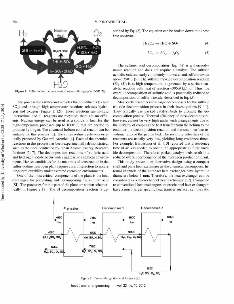
Figure 1 Sulfur-iodine thermo chemical water splitting cycle (DOE [2]).
The process uses water and recycles the constituents (I2 andSO2) and through high-temperature reactions releases hydro-gen and oxygen (Figure 1; [2]). These reactions are in-fluidinteractions and all reagents are recycled; there are no efflu-ents. Nuclear energy can be used as a source of heat for thehigh-temperature processes (up to 1000◦C) that are needed toproduce hydrogen. The advanced helium-cooled reactor can besuitable for this process [3]. The sulfur iodine cycle was orig-inally proposed by General Atomics [4]. Each of the chemicalreactions in this process has been experimentally demonstrated,such as the ones conducted by Japan Atomic Energy ResearchInstitute [5, 7]. The decomposition reactions of sulfuric acidand hydrogen iodide occur under aggressive chemical environ-ments. Hence, candidates for the materials of construction in thesulfur–iodine hydrogen plant require careful selection to ensurelong-term durability under extreme corrosion environments.
One of the most critical components of the plant is the heatexchanger for preheating and decomposing the sulfuric acid(SI). The processes for this part of the plant are shown schemat-ically in Figure 2 [8]. The SI decomposition reaction is de-
scribed by Eq. (2). The equation can be broken down into thesetwo reactions:
H2SO4 → H2O + SO3 (4)
SO3 → SO2 + 1/2O2 (5)
The sulfuric acid decomposition (Eq. (4)) is a thermody-namic reaction and does not require a catalyst. The sulfuricacid dissociates nearly completely into water and sulfur trioxideabove 350◦C [9]. The sulfuric trioxide decomposition reaction(Eq. (5)) is at high temperature, augmented by a surface cat-alytic reaction with heat of reaction –395.9 kJ/mol. Thus, theoverall decomposition of sulfuric acid is practically reduced todecomposition of sulfur trioxide, described in Eq. (5).
Most early researchers use large decomposers for the sulfurictrioxide decomposition process in their investigations [9–11].They typically use packed catalyst beds to promote the de-composition process. Thermal efficiency of these decomposers,however, cannot be very high under such arrangements due tothe inability of coupling the heat transfer from the helium to theendothermic decomposition reaction and the small surface-to-volume ratio of the pebble bed. The resulting velocities of thereactants are usually very low, yielding long residence times.For example, Barbarossa et al. [10] reported that a residencetime of 46 s is needed to obtain the appropriate sulfuric triox-ide decomposition. Therefore, packed catalyst beds result in areduced overall performance of the hydrogen production plant.
This study presents an alternative design using a compactshell and plate heat exchanger as the chemical decomposer. In-ternal channels of the compact heat exchanger have hydraulicdiameters below 1 mm. Therefore, the heat exchanger can beconsidered as a microchannel heat exchanger [12]. Comparedto conventional heat exchangers, microchannel heat exchangershave a much larger specific heat transfer surface; i.e., the ratio
Figure 2 Process design (General Atomics [8]).
heat transfer engineering vol. 33 no. 10 2012
Dow
nloa
ded
by [
Uni
vers
ity o
f W
inds
or]
at 0
2:28
17
July
201
4
V. PONYAVIN ET AL. 855
between the active heat transfer area and the volume is muchlarger. By adopting a compact design, the high-temperature he-lium source can effectively transfer its heat to the gaseous sul-furic trioxide stream and decompose it into sulfur dioxide andoxygen. Silicone carbide (SiC) is a suitable candidate materialfor this application because of its superior corrosion and creepresistance under these environments, which combine high tem-peratures and high acid concentrations. The following is a briefsurvey of previous uses of silicone carbide in this area.
A modular ceramic chemical decomposer (microreactor)with exchangeable catalytic carrier plates, fabricated by injec-tion molding, was previously presented in Knitter et al. [13].This microreactor was used for catalyst screening and high-temperature gas-phase reactions up to 1000◦C [14]. A catalyticceramic plate heat exchanger/reactor has been represented inSchmitt et al. [15]. This reactor was used to investigate themethanation process in the 180–290◦C temperature range. Ad-ditionally, the use of ceramic microreactors with wall-coatedcatalyst for steam reforming of methanol was reported by Co-nant et al. [16]. This microreactor included gas channels with di-ameters between 0.23 to 0.45 mm and operated at about 230◦C.
A two-dimensional numerical model to predict decomposi-tion of sulfur trioxide in a tubular reactor was developed byMuramalla et al. [17]. It was shown that the decomposition ofsulfur trioxide depends on different parameters such as wall sur-face temperature, molar flow rate of the reacting mixture, andthe diameter of the reactor tube. Subramanian et al. [18] cre-ated a three-dimensional numerical model to predict the overallperformance of an advanced high-temperature heat exchanger(HTHX) up to 1000◦C; its application was for the sulfur iodinecycle to produce hydrogen using an advanced nuclear reactor asthe heat source.
Because SO3 decomposition is a surface reaction, the de-composition yield can be enhanced by increasing the contactarea between flow and walls of the channels. Another way toenhance sulfur trioxide decomposition yield is to increase theresidence time of sulfuric acid gases in the decomposer; thiscan be done by decreasing the mass flow rate or increasing theoperating pressure of the sulfuric acid gases (at constant massflow rate).
Parametric studies of the decomposition yield (percentage)of the surface reaction in decomposers have been explored byseveral researchers. The following is a brief survey of someof the relevant research in this area. Sato et al. [19], Tagawaand Endo [9], Lin and Flaherty [11], and Ishikawa et al. [20]completed parametric studies of SO3 decomposition processin pebble bed reactors for different reactant mass flow rates.They concluded that SO3 decomposition percentage increaseswith decreasing reactant mass flow rates. The maximum SO3
decomposition percentage, 90%, was obtained in the researchof Sato et al. [19]. Deshmukh et al. [21] modeled ammoniadecomposition for hydrogen production in an aluminum mi-croreactor that incorporated a network of posts to enhance theprimary surfaces. It was shown that posts play an important rolein enhancing the transverse mass transfer, provide high cata-
lyst surface area, and provide interesting back-diffusing flowpatterns that occur at lower flow rates. This parametric studyinvestigated the trade-off between pressure drop and conversionunder certain conditions. The authors showed that breakdown ofthe thermal and hydraulic boundary layers in internal channelsof the decomposer can boost the heat transfer and, consequently,increase the decomposition rate. Other complex geometry chan-nels can be used for this purpose with a penalty in pressure dropand manufacturing complexity. Muramalla et al. [17] developeda two-dimensional numerical model to predict decomposition ofsulfur trioxide in a tubular duct for the production of hydrogenusing the S-I water splitting cycle. They showed that the decom-position of sulfur trioxide depends on different parameters suchas wall surface temperature, molar flow rate of the reactants,and the diameter of the reactor tube. These results indicated thatmore decomposition occurs at higher wall surface temperatures,smaller diameters of reactor tube, and for low mole flow ratesof the reacting mixture.
Several researchers considered the use of different geome-tries for the heat exchanger channels to enhance the heat transfercoefficient. The effect of different corrugated structures on thelocal and overall heat and mass transfer in heat exchangers werediscussed in Zimmerer et al. [22]. It was shown that the flowphenomena caused by the different geometries were of signif-icant influence on the homogeneity and on the magnitudes ofthe local heat and mass transfer as well as the pressure drop.Qi et al. [23] analyzed several factors affecting the heat transferand pressure drop of a heat exchanger with corrugated louveredfins. These results show that flow depth, ratio of fin pitch and finthickness, and the number of the louvers significantly influencethe thermal hydraulic performance of the heat exchanger withcorrugated louvered fins. Yun and Lee [24] experimentally in-vestigated the effects of the shapes of interrupted surfaces on theperformance of the fin-and-tube heat exchanger used in homeair conditioners. In this study the heat transfer and pressure dropcharacteristics of the three kinds of fin shapes were also com-pared and an optimal fin shape for home air conditioners wasrecommended.
A systematic analysis of the effect of various design param-eters on the heat transfer and pressure drop characteristics ofa heat exchanger with slit fins was conducted by Yun and Lee[25]. The results allowed for quantitative estimation of the vari-ous parameters affecting heat exchanger performance, and thusthe main factors for optimal design of a heat exchanger are iden-tified. Subramanian at al. [26] analyzed fin shape (rectangularand rounded) and offset gap effects on the friction factor andthermal performance of a high-temperature offset strip-fin heatexchanger. It was observed that the heat exchanger channelswith curved fin edges yielded a better overall performance bylowering the pumping power.
The process of SO3 decomposition occurs under highpressure and temperature gradients that can cause highthermal/mechanical stresses. However, there is little availableliterature about thermal/mechanical stress analysis of SO3
decomposers.
heat transfer engineering vol. 33 no. 10 2012
Dow
nloa
ded
by [
Uni
vers
ity o
f W
inds
or]
at 0
2:28
17
July
201
4
856 V. PONYAVIN ET AL.
Figure 3 Shell and plate heat exchanger and decomposer (Wilson [27]).
This study presents a three-dimensional conjugate heat trans-fer, chemical, fluid flow model for a compact SI decomposer.The results of this model are extended to develop an approachfor thermal/mechanical stress analysis to assess the performanceof the decomposer. Also, a parametric study of regular linearchannel designs is conducted. The objective of this study isto improve the sulfur trioxide decomposition percentage withrespect to the initial design. Additionally, the effect of vary-ing channel geometry of the chemical decomposer is explored.These designs are assessed in terms of their productivity andinduced stresses under steady-state conditions.
DESIGN OF SHELL-AND-PLATE HEAT EXCHANGERAND DECOMPOSER
The baseline design of the shell-and-plate heat exchanger anddecomposer was developed by Ceramatec, Inc. (Salt Lake City,UT), and is shown in Figure 3 [27]. Hot helium from nuclearreactor (T = 975◦C) is used to heat the SI feed components(H2O, H2SO4, SO3) to the appropriate condition for the SI de-composition reaction (T > 850◦C). Platinum catalyst is used toenhance decomposition.
This article addresses the analysis of decomposer 1 (FIG-URE 2), which is chosen because of its complex nature andthe presence of chemical reactions. The preheater and decom-poser 2 are similar in design but are less demanding in terms ofchemical reactions or heat transfer. Therefore, the results of theanalysis may be applicable to these stages of the heat exchanger.Assembly of decomposer 1 is shown in Figure 4. The layers ofdecomposer 1 are shown in Figure 5, where S1 layers containmicrochannels for the reacting gases; S2 layers provide inlet andoutlet manifolds for the gases; the SP layer is used for heliumflow; and HT layers provide heat transfer between flows.
SINGLE-CHANNEL MODEL AND BOUNDARYCONDITIONS
To improve the performance of the heat exchanger and de-composer, the mass flow rate should be well distributed among
all channels. Given this assumption of uniform flow rate distri-bution, a single-channel model is developed to reduce compu-tation load. The geometry of the single channel model is shownin Figure 6. The computational model requires only one half ofan internal channel due to the existence of a symmetry plane,as in Figures 6 and 7. The original dimensions for the geometry(baseline design) are:
hS P =0.85 mm; hH T =0.3 mm; hS1 =0.424 mm;hH T +S2a = 0.75 mm; h1/2S2b
= 0.225 mm;
W1 = 0.635 mm; W2 = 0.381 mm; L = 52.324 mm.
Geometry of the model and its associated mesh were cre-ated using mesh generator Gambit version 2.2 [28]; the meshedmodel is shown in Figure 8. The mesh was refined in the neigh-borhood of the interfaces between liquid and solid volumes.These studies investigated the dependence of the calculated pa-rameters (pressure, temperature, velocities) on mesh coarseness.After experimenting with several mesh densities, the one of Fig-ure 8 was yielded the most stable results. Further reduction ofelement sizes did not significantly affect the results.
The inlet mass flow rates for each channel were based onoverall mass flow rate of helium of 71 kg/h and SI flow rateof 158.66 kg/h. In addition to the inlet conditions of Table 1,the boundary conditions on the top, bottom, left, and right sideswere planes of symmetry. The thermal boundary conditionsfor the front and back sides were adiabatic. Inlet velocity pro-files were uniform. Velocity calculations were based on area,density, and mass flow rate of the input data and model ge-ometry. Pressure-outlet boundary conditions were used as theoutflow conditions by specifying a static (gauge) pressure atthe outlet boundary. The calculation domain and boundaries areshown in Figure 9. This design is labeled as the baseline de-sign in the remainder of this paper. The operating pressure is1.5 MPa.
MATERIAL PROPERTIES
A detailed study of material properties of SiC is presented inMunro [29]. The following equation represents the polynomialinterpolation for the thermal conductivity versus temperature
Table 1 Inlet conditions for the three fluid of the decomposer
Inlet conditions for He part:m = 1.409 × 10⁻⁶kg/s; T = 1223.15K (950◦C).
SI inlet for the reacting flow:m = 3.148 × 10⁻⁶kg/s; T = 974.9K (701.75◦C);xSO3 = 0.8163; xSO2 = 0; xO2 = 0; xH2 O = 0.1837
SI inlet for nonreacting flow:m = 3.148 × 10⁻⁶kg/s; = T = 974.9K (701.75◦C);xSO3 = 0; xSO2 = 0.6532; xO2 = 0.1631; xH2 O = 0.1837
heat transfer engineering vol. 33 no. 10 2012
Dow
nloa
ded
by [
Uni
vers
ity o
f W
inds
or]
at 0
2:28
17
July
201
4
V. PONYAVIN ET AL. 857
Figure 4 Schematic of decomposer 1 assembly (Wilson [27]).
(K) curve for SiC:
kSiC = 1.9477 · 102 − 3.60612 · 101 · T + 3.30843 · 104 · T 2
−1.46006 · 10−7 · T 3 + 2.7588 · 1011 · T 4
(6)The density and specific heat of SiC do not vary significantly
as temperature changes, and because of these analyses wereat static conditions, the properties are assumed to be constantfor the temperature range of the heat exchanger (973–1223 K).These values are ρSiC = 3130 kg/m3 and CpSiC = 1200 J/(kg·K).
The heat exchanger material tensile strength varies with tem-perature according to the following equation [29]:
sut = 0.0142857 · T + 200M Pa (7)
Figure 5 Layers of decomposer 1 (Wilson [27]).
The properties (density, viscosity, heat capacity, and thermalconductivity) for each of the gaseous constituents were takenfrom the FLUENT database [30]. The mixed gas properties forthese species, with and without chemical reactions, are found inFigure 7, and were calculated using FLUENT 6.2.16 software[30]. The mass fractions for each component were calculatedusing:
xi = φi Mi∑ni=1 φi Mi
(8)
The mixture density was computed as:
ρ = pop
RT∑
ixiMi
(9)
The thermal conductivity and molecular viscosity of the mix-ture were calculated based on kinetic theory as:
k =∑
i
xi ki∑j x jηi j
(10)
µ =∑
i
xiµi∑j x jηi j
(11)
where
ηi j =
[1 +
(µi
µ j
) 12(
M j
Mi
) 14
]2
[8(
1 + MiM j
)] 12
(12)
heat transfer engineering vol. 33 no. 10 2012
Dow
nloa
ded
by [
Uni
vers
ity o
f W
inds
or]
at 0
2:28
17
July
201
4
858 V. PONYAVIN ET AL.
Figure 6 Extraction of the single-channel geometry from the large-scale design.
The mixture’s specific heat capacity was calculated as a massfraction average of the pure species heat capacities:
Cp =∑
i
xi Cpi (13)
FLUID FLOW, HEAT TRANSFER, AND CHEMICALREACTION MODELING
The governing equations for continuity, momentum, and en-ergy for the computational domain can be expressed in tensorform as follows:
∂
∂wi(ρui ) = 0 (14)
Figure 7 Sketch of the single-channel geometry.
∂
∂wi(ρui uk) = ∂
∂wi
(µ
∂uk
∂wi
)− ∂p
∂wk(15)
∂
∂wi(ρui T ) = ∂
∂wi
(k
Cp
∂T
∂wi
)+ Sh (16)
Figure 8 Mesh and computational area (163,735 nodes 145,800 cells).
heat transfer engineering vol. 33 no. 10 2012
Dow
nloa
ded
by [
Uni
vers
ity o
f W
inds
or]
at 0
2:28
17
July
201
4
V. PONYAVIN ET AL. 859
Figure 9 Calculation domain and boundaries.
With proper control of the grid density, the computationaldomain can be divided into four main regions: helium flow,reacting flow, product flow, and silicon carbide domain (Figure7). The governing equation for the different species involved inthe reaction can be written as follows:
∂
∂w j
(ρDi,m
∂xi
∂w j− ρu j xi
)+ Pi + Si = 0 (17)
The wall surface reaction model is implemented to determinethe mole fractions of SO3, SO2, H2O, and O2. The reaction ratewas obtained by using the Arrhenius equation [31]:
K = Ae( −EaRT ) (18)
Using the experimental results for the platinum catalystreported in Ginosar [32], the following coefficients are used:Ea = 3.267·107 J/kmol and A = 0.16 s−1.
The governing equations are solved in the Cartesian coordi-nate system using a controlled volume finite-difference methodusing the approach introduced by Patankar [33]. The general-purpose computational fluid dynamics (CFD) code of FLUENT6.2.16 software [30] is used as the numerical solver for the prob-lem. A nonstaggered grid storage scheme is adapted to definethe discrete control volumes. In this scheme, the same con-trol volume is employed for the integration of all conservationequations. All variables are stored at the control volume’s cellcenter. The numerical scheme used in this study is the power-law differencing scheme. A segregated solver is used in thisproblem. The SIMPLE algorithm is used to resolve the cou-pling between pressure and velocity. The governing equations,which are discrete and nonlinear, are linearized using an implicittechnique with respect to the set of dependent variables. In theimplicit technique, the unknown value in each cell is computedusing a relation that includes both existing and unknown values
from neighboring cells. Therefore, each unknown will appearin more than one equation in the system, and these equationsmust be solved simultaneously to give the unknown quantities.The resulting algebraic equations are solved iteratively using anadditive correction multigrid method with a Gauss–Seidel re-laxation procedure. The average convergence time of the modelwas 12 h for 30,000 iterations.
STRESS ANALYSIS
Recently, the strength of ceramics has been routinely ana-lyzed using a Weibull statistical approach [34]. This approachis very popular because of its ease of application and ability topredict failure of brittle materials. According to this approach,the cumulative probability of failure of a brittle component thatis subjected to an applied stress field σ is generally written as
P f = 1 − e− ∫
x
(σ−σu
σ0
)mdx
(19)
The integral is defined as the risk of rupture, Rr. The in-tegration may be carried out over the entire specimen volumeor surface area, depending upon the location of failure-causingflaws. Accordingly, the variable x is replaced by area A or vol-ume V as follows:
P f = 1 − e− ∫
V
(σ−σu
σ0
)mdV
(20)
If the preceding integration is computed over a unit volumeand the value of σu is taken to be zero, the probability of failurebecomes
P f = 1 − e−
(σσ0
)m
(21)
heat transfer engineering vol. 33 no. 10 2012
Dow
nloa
ded
by [
Uni
vers
ity o
f W
inds
or]
at 0
2:28
17
July
201
4
860 V. PONYAVIN ET AL.
The preceding equation can be further rearranged:
ln(1 − P f
) = −(
σ
σ0
)m
(22)
−ln(1 − P f
) =(
σ
σ0
)m
(23)
ln
(ln
(1
1 − P f
))= m ln (σ) − m ln (σ0) (24)
This equation represents a straight line equation betweenln(ln( 1
1−P f)) and ln (σ). Using this formulation, the parameters
of the equation, m and σ0, are easily derived from the results ofexperimental testing.
The approach just described can be adapted in finite-element analysis by performing numerical integration of((σi – σu)/σ0)m over the volume as shown in the followingequation:
P f = 1 − e− ∑N
i=1
((σi −σu
σ0
)mvi
)(25)
where N is the total number of elements, vi is a nondimensionalvolume of element i, which is expressed in form of (Vi/V), Vi
is the actual volume of element i, and V is the total volume ofthe solid part.
The following steps can be used to incorporate Weibull distri-bution within finite-element analysis to calculate the probabilityof failure:
1. For each element, extract element volume (Vi), element nodalconnectivity information, and the three principal stresses σi1,σi2, and σi3.
2. Extract nodal temperatures.3. Calculate average temperature for each element.4. Calculate the mechanical strength of the material at the tem-
perature obtained in the previous step according to Eq. (7).5. If a stress component is compressive, equate it to zero, as
ceramics mainly fail due to tensile stresses, and calculate theprobability of failure of the solid part for each of the threeprincipal stresses.
Temperature distribution of the solid part of the decomposeris imported to ANSYS [35] by using the volume mapping func-tion of FLUENT [30]. Thermal loads are used to calculatestresses in the solid part of the model. As mentioned earlier,a uniform pressure of 1.5 MPa is applied to all surfaces thatare adjacent to fluid flow. Figure 10 shows the boundary condi-tions used in stress analysis. A uniform mesh, Figure 11, is usedto calculate stresses. This mesh density was selected based onconditions of stability studies.
Figure 10 Displacement restrictions for the stress analysis.
RESULTS OF THE BASELINE DESIGN CALCULATIONS
Flow calculations of sulfur trioxide decomposition (2SO3 →2SO2+O2) for the one-channel geometry with platinum catalystwere performed and indicated the SO3 mole fraction reductionin the reacting flow channel. Mole fractions of SO2 and O2,respectively, increased along the reacting flow direction. Molefractions of the reaction products at the outlet of the reactionchannel were xSO2 = 0.254 and xO2 = 0.127.
According to the calculations, the molar decomposition per-centage of the sulfur trioxide (SO3) was 63.81. The mass flow
Figure 11 Stress analysis mesh (63,342 nodes and 55,200 elements).
heat transfer engineering vol. 33 no. 10 2012
Dow
nloa
ded
by [
Uni
vers
ity o
f W
inds
or]
at 0
2:28
17
July
201
4
V. PONYAVIN ET AL. 861
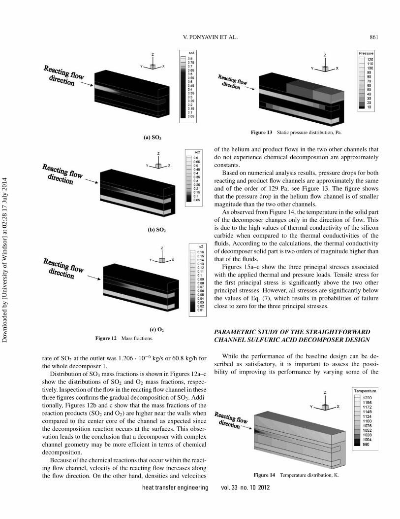
Figure 12 Mass fractions.
rate of SO2 at the outlet was 1.206 · 10−6 kg/s or 60.8 kg/h forthe whole decomposer 1.
Distribution of SO3 mass fractions is shown in Figures 12a–cshow the distributions of SO2 and O2 mass fractions, respec-tively. Inspection of the flow in the reacting flow channel in thesethree figures confirms the gradual decomposition of SO3. Addi-tionally, Figures 12b and c show that the mass fractions of thereaction products (SO2 and O2) are higher near the walls whencompared to the center core of the channel as expected sincethe decomposition reaction occurs at the surfaces. This obser-vation leads to the conclusion that a decomposer with complexchannel geometry may be more efficient in terms of chemicaldecomposition.
Because of the chemical reactions that occur within the react-ing flow channel, velocity of the reacting flow increases alongthe flow direction. On the other hand, densities and velocities
Figure 13 Static pressure distribution, Pa.
of the helium and product flows in the two other channels thatdo not experience chemical decomposition are approximatelyconstants.
Based on numerical analysis results, pressure drops for bothreacting and product flow channels are approximately the sameand of the order of 129 Pa; see Figure 13. The figure showsthat the pressure drop in the helium flow channel is of smallermagnitude than the two other channels.
As observed from Figure 14, the temperature in the solid partof the decomposer changes only in the direction of flow. Thisis due to the high values of thermal conductivity of the siliconcarbide when compared to the thermal conductivities of thefluids. According to the calculations, the thermal conductivityof decomposer solid part is two orders of magnitude higher thanthat of the fluids.
Figures 15a–c show the three principal stresses associatedwith the applied thermal and pressure loads. Tensile stress forthe first principal stress is significantly above the two otherprincipal stresses. However, all stresses are significantly belowthe values of Eq. (7), which results in probabilities of failureclose to zero for the three principal stresses.
PARAMETRIC STUDY OF THE STRAIGHTFORWARDCHANNEL SULFURIC ACID DECOMPOSER DESIGN
While the performance of the baseline design can be de-scribed as satisfactory, it is important to assess the possi-bility of improving its performance by varying some of the
Figure 14 Temperature distribution, K.
heat transfer engineering vol. 33 no. 10 2012
Dow
nloa
ded
by [
Uni
vers
ity o
f W
inds
or]
at 0
2:28
17
July
201
4
862 V. PONYAVIN ET AL.
Figure 15 Principal stresses distribution, Pa.
Figure 16 Percentage decomposition of SO3 versus different mass flow ratesin the reacting flow.
operating conditions. Therefore, the effects of mass flow ratesof the reacting flow, channel length, and operating pressure arestudied. Table 2 lists the ranges of these variables. In all con-sidered cases, equal pressure is applied to the three channels.The same mass flow rate is used in the reacting flow and theproduct flow channels in all cases. The mass flow rate in thehelium channel is constant in every case.
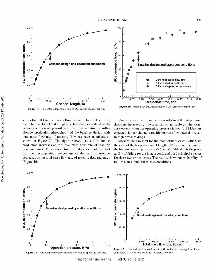
Figure 16 shows that the percentage decomposition of SO3
increases significantly as the mass flow rate of the reacting flowdecreases, which is consistent with the general observation forslower flow, longer residence time conditions. The percentagedecomposition of SO3 also depends on the channel length, asshown in Figure 17. According to this figure, the decomposi-tion rate increases with the increase of the channel length. Thepercentage of SO3 decomposition increases significantly as theoperating pressure of the reacting flow increases; see Figure 18.Mass flow rate is kept the same in this case. The increase inthe SO3 percentage decomposition is due to the increase of theresidence time of the reactant fluid as the operation pressureincreases.
It can be shown that residence time is the common themebetween all these parametric studies of mass flow rate, channellength, and pressure. The residence time has been calculatedbased on average flow velocity. These results are combinedin Figure 19 using residence time as abscissa. The figure
Table 2 Ranges of parameters used to evaluate baseline design
Parameter Lower limit Upper limit
Mass flow rates of the reacting flow (kg/s) 1.6E-6 1.6E-5Channel length (m) 0.0087 0.21Operating pressures (MPa) 0.1 7.5
heat transfer engineering vol. 33 no. 10 2012
Dow
nloa
ded
by [
Uni
vers
ity o
f W
inds
or]
at 0
2:28
17
July
201
4
V. PONYAVIN ET AL. 863
Figure 17 Percentage decomposition of SO3 versus channel length.
shows that all three studies follow the same trend. Therefore,it can be concluded that a higher SO3 conversion rate stronglydepends on increasing residence time. The variation of sulfurdioxide production (throughput) of the baseline design withtotal mass flow rate of reacting flow has been calculated asshown in Figure 20. The figure shows that sulfur dioxideproduction increases as the total mass flow rate of reactingflow increases. This observation is independent of the factthat the decomposition percentage of the sulfuric trioxidedecreases as the total mass flow rate of reacting flow increases(Figure 16).
Figure 18 Percentage decomposition of SO3 versus operating pressure.
Figure 19 Percentage decomposition of SO3 versus residence time.
Varying these three parameters results in different pressuredrops in the reacting flows, as shown in Table 3. The worstcase occurs when the operating pressure is low (0.1 MPa). Asexpected, longer channels and higher mass flow rates also resultin high pressure drops.
Stresses are assessed for the most critical cases, which arethe case of the longest channel length (0.21 m) and the case ofthe highest operating pressure (7.5 MPa). Table 4 lists the prob-ability of failure for the first, second, and third principal stressesfor these two critical cases. The results show that probability offailure is minimal under these conditions.
Figure 20 Sulfur dioxide mass flow rate at the output of reacting flow channel(throughput) versus total reacting flow mass flow rate.
heat transfer engineering vol. 33 no. 10 2012
Dow
nloa
ded
by [
Uni
vers
ity o
f W
inds
or]
at 0
2:28
17
July
201
4
864 V. PONYAVIN ET AL.
Figure 21 Ribbed lower surface channel, case 2 and case 3.
RESULTS OF ALTERNATIVE DECOMPOSERCHANNEL DESIGNS
To enhance the performance of the decomposer, alternativedesigns are explored. These alternative designs can provide thenecessary breakdown of the thermal and hydraulic boundarylayers to boost the heat transfer. On the other hand, these de-signs will increase the pressure drop and thermal/mechanicalstresses. These designs were chosen as they were deemed fea-sible to manufacture by Ceramatec personnel. The proposed
designs differ from the baseline design only in the geome-try of the reacting flow channel. All other dimensions aresimilar to the baseline design (case 1). Five alternative designsare investigated:
• Ribbed lower surface channel (case 2). The height of the rib,h, is equal to 0.1 mm, as in Figure 21.
• Ribbed lower surface channel (case 3). The height of the rib,h, is equal to 0.2 mm, as in Figure 21.
• Two hexagonal layers channel with 50% overlap (case 4), asin Figure 22.
Figure 22 Two hexagonal layers channel with 50% of layers overlapping, case 4.
heat transfer engineering vol. 33 no. 10 2012
Dow
nloa
ded
by [
Uni
vers
ity o
f W
inds
or]
at 0
2:28
17
July
201
4
V. PONYAVIN ET AL. 865
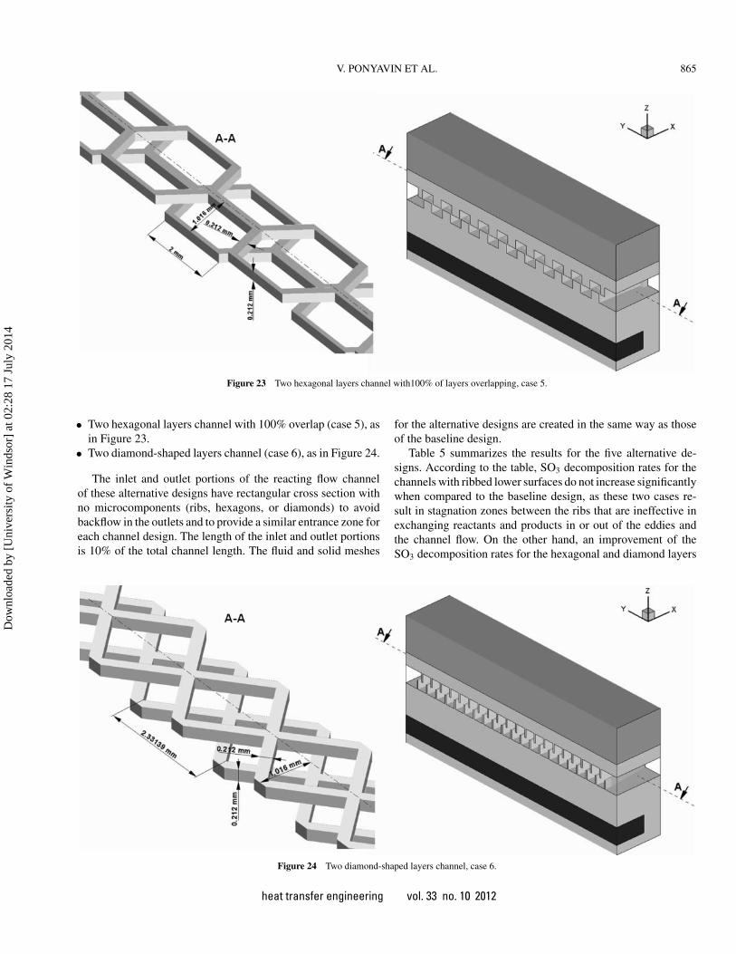
Figure 23 Two hexagonal layers channel with100% of layers overlapping, case 5.
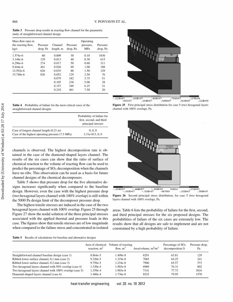
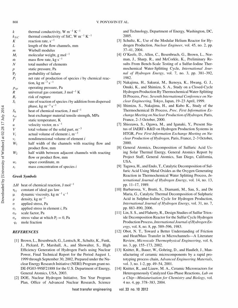
• Two hexagonal layers channel with 100% overlap (case 5), asin Figure 23.
• Two diamond-shaped layers channel (case 6), as in Figure 24.
The inlet and outlet portions of the reacting flow channelof these alternative designs have rectangular cross section withno microcomponents (ribs, hexagons, or diamonds) to avoidbackflow in the outlets and to provide a similar entrance zone foreach channel design. The length of the inlet and outlet portionsis 10% of the total channel length. The fluid and solid meshes
for the alternative designs are created in the same way as thoseof the baseline design.
Table 5 summarizes the results for the five alternative de-signs. According to the table, SO3 decomposition rates for thechannels with ribbed lower surfaces do not increase significantlywhen compared to the baseline design, as these two cases re-sult in stagnation zones between the ribs that are ineffective inexchanging reactants and products in or out of the eddies andthe channel flow. On the other hand, an improvement of theSO3 decomposition rates for the hexagonal and diamond layers
Figure 24 Two diamond-shaped layers channel, case 6.
heat transfer engineering vol. 33 no. 10 2012
Dow
nloa
ded
by [
Uni
vers
ity o
f W
inds
or]
at 0
2:28
17
July
201
4
866 V. PONYAVIN ET AL.
Table 3 Pressure drop results in reacting flow channel for the parametricstudy of straightforward channel design
Table 4 Probability of failure for the most critical cases of thestraightforward channel designs
Probability of failure forfirst, second, and third
principal stresses
Case of longest channel length (0.21 m) 0, 0, 0Case of the highest operating pressure (7.5 MPa) 3.31e-013, 0, 0
channels is observed. The highest decomposition rate is ob-tained in the case of the diamond-shaped layers channel. Theresults of the six cases can show that the ratio of surface ofchemical reaction to the volume of reacting flow can be used topredict the percentage of SO3 decomposition when the channelshave no ribs. This observation can be used as a basis for futurechannel designs of the chemical decomposers.
Table 5 shows that pressure drop for the five alternative de-signs increases significantly when compared to the baselinedesign. However, even the case with the highest pressure drop(two hexagonal layers channel with 100% overlap) is still withinthe 5000 Pa design limit of the decomposer pressure drop.
The highest tensile stresses are induced in the case of the twohexagonal layers channel with 100% overlap. Figure 25 throughFigure 27 show the nodal solution of the three principal stressesassociated with the applied thermal and pressure loads in thiscase. The figures show that tensile stresses are of low magnitudewhen compared to the failure stress and concentrated in isolated
Figure 25 First principal stress distribution for case 5 (two hexagonal layerschannel with 100% overlap), Pa.
Figure 26 Second principal stress distribution, for case 5 (two hexagonallayers channel with 100% overlap), Pa.
areas. Table 6 lists the probability of failure for the first, second,and third principal stresses for the six proposed designs. Theprobabilities of failure of the six cases are extremely low. Theresults show that all designs are safe to implement and are notconstrained by a high probability of failure.
Table 5 Results of calculations for baseline and alternative designs
Figure 27 Third principal stress distribution, for case 5 (two hexagonal layerschannel with 100% overlap), Pa.
CONCLUSIONS
The sulfuric acid decomposer is an important part of theproposed hydrogen production plant. A design for a siliconecarbide decomposer with microchannels and platinum catalystis proposed as it offers the potential for superior performancewhen compared to traditional designs. The decomposer per-forms sulfur trioxide decomposition (2SO3 → 2SO2 + O2). Athree-dimensional computational model for chemical reaction,fluid flow, and heat transfer within a single channel of the de-composer is developed. The resulting temperature distributionwithin this model is imported to an additional finite-elementanalysis package where thermal and pressure loads were usedto calculate stresses.
Hydrodynamics and thermal numerical modeling coupledwith sulfur trioxide decomposition of a ceramic SI decomposerwith linear channels is performed.
The maximal pressure drop for the channels is 129 Pa. Con-sidering that the allowable pressure drop limit for the design isaround 5000 Pa (based on Ceramatec, Inc., requirements; [27]),it can be found that the pressure drops is acceptable. The mo-lar SO3 decomposition percentage for the design is 63.8%. The
mass flow rate of SO2 at the outlet is 1.206 · 10−6 kg/s or 60.8kg/h for the whole decomposer 1.
The baseline design has near zero probability of failure, asSiC has an extremely high coefficient of thermal conductivity,which eliminates thermal gradients, so it can be concluded thatthe investigated designs are safe under the proposed operatingconditions.
The sulfur trioxide decomposition reaction is a surface reac-tion. Therefore, the decomposition percentage can be substan-tially enhanced by increasing the contact surface between flowand wall.
A parametric study is performed on the baseline design. Vari-ations of mass flow rates in the reacting flow channel and overalllength of the decomposer are considered. Results show that de-composition percentage can be increased when the residencetime is increased by reducing the reactants’ mass flow rate, bylengthening the channels, or by increasing the operation pres-sure. This performance improvement is associated with a risein pressure drops in some cases. Stress analysis shows that theprobabilities of failure in the highest stress cases of this para-metric study are still quite limited.
Five alternative geometries of the decomposer microchannelsare investigated: two ribbed lower surface channels with differ-ent rib heights, two hexagonal layers channel with 50% and100% overlap, respectively, and diamond-shaped layers chan-nel. The results show that ribbed lower surface channels provideminimal increase in the decomposition percentages. On the otherhand, hexagonal and diamond-shaped channels provide betterdecomposition percentages. The best results are obtained in thecase of diamond-shaped channels. The five alternate designshave higher pressure drops when compared to the baseline de-sign. All considered designs have very low probability of failure,as silicon carbide has an extremely high coefficient of thermalconductivity, which eliminates thermal gradients within channelwalls and maintains low stresses.
NOMENCLATURE
A pre-exponential factor, s−1
Cp specific heat at constant pressure, J kg−1 K−1
Di,m diffusion coefficient for species i in the mixture, m2
s−1
Ea activation energy, J/kmolh height of the rib, mmhH T thickness of layer between reacting flow and helium,
mmhH T +S2a thickness of layer between product flow and reacting
flow, mmhS P half thickness of helium channel, mmhS1 thickness of reacting flow and product flow channels,
mmh1/2S2b half thickness of layer between product flow channels,
mm
heat transfer engineering vol. 33 no. 10 2012
Dow
nloa
ded
by [
Uni
vers
ity o
f W
inds
or]
at 0
2:28
17
July
201
4
868 V. PONYAVIN ET AL.
k thermal conductivity, W m−1 K−1
kSiC thermal conductivity of SiC, W m−1 K−1
K reaction rate, s−1
L length of the flow channels, mmm Wiebull modulusMi molecular weight, g mol−1
m mass flow rate, kg s−1
N total number of elementsp static pressure, PaPf probability of failurePi net rate of production of species i by chemical reac-
tion, kg m−3 s−1
pop operating pressure, PaR universal gas constant, J mol−1 KRr risk of ruptureSi rate of reaction of species i by addition from dispersed
phase, kg m−3 s−1
Sh heat of chemical reaction, J mol−1
sut heat exchanger material tensile strength, MPaT static temperature, Ku velocity vector, m s−1
V total volume of the solid part, m−3
Vi actual volume of element i, m−3
vi nondimensional volume of element iW1 half width of the channels with reacting flow and
product flow, mmW2 half width between adjacent channels with reacting
flow or product flow, mmwi space coordinate, mxi mass concentration of species i
Greek Symbols
�H heat of chemical reaction, J mol−1
ηi j constant of ideal gas lawµ dynamic viscosity, kg m−1 s−1
ρ density, kg m−3
σ applied stress, Paσi applied stress in element i, Paσ0 scale factor, Paσu stress value at which Pf = 0, Paϕi mole fraction
REFERENCES
[1] Brown, L., Besenbruch, G., Lentsch, R., Schultz, K., Funk,J., Pickard, P., Marshall, A., and Showalter, S., HighEfficiency Generation of Hydrogen Fuels using NuclearPower, Final Technical Report for the Period August 1,1999 through September 30, 2002, Prepared under the Nu-clear Energy Research Initiative (NERI) Program grant no.DE-FG03-99SF21888 for the U.S. Department of Energy,General Atomics, USA, 2003.
[2] DOE, Nuclear Hydrogen Initiative, Ten Year ProgramPlan, Office of Advanced Nuclear Research, Science
and Technology, Department of Energy, Washington, DC,2005.
[3] Schultz, K., Use of the Modular Helium Reactor for Hy-drogen Production, Nuclear Engineer, vol. 45, no. 2, pp.37–41, 2004.
[4] O’Keefe, D., Allen, C., Besenbruch, G., Brown, L., Nor-man, J., Sharp, R., and McCorkle, K., Preliminary Re-sults From Bench-Scale Testing of a Sulfur-Iodine Ther-mochemical Water-Splitting Cycle, International Jour-nal of Hydrogen Energy, vol. 7, no. 3, pp. 381–392,1982.
[5] Nakajima, H., Sakurai, M., Ikenoya, K., Hwang, G. J.,Onuki, K., and Shimizu, S. A., Study on a Closed-CycleHydrogen Production By Thermochemical Water-SplittingIS Process, Proc. Seventh International Conference on Nu-clear Engineering, Tokyo, Japan, 19–23 April, 1999.
[6] Shimizu, S., Nakajima, H., and Kubo K., Study of theThermochemical IS Process, Proc. First Information Ex-change Meeting on Nuclear Production of Hydrogen, Paris,France, 2–3 October, 2000.
[7] Shiozawa, S., Ogawa, M., and Iganaki, Y., Present Sta-tus of JAERI’s R&D on Hydrogen Production Systems inHTGR, Proc First Information Exchange Meeting on Nu-clear Production of Hydrogen, Paris, France, 2–3 October,2000.
[8] General Atomics, Decomposition of Sulfuric Acid Us-ing Solar Thermal Energy, General Atomics Report byProject Staff, General Atomics, San Diego, California,USA.
[9] Tagawa, H., and Endo, T., Catalytic Decomposition of Sul-furic Acid Using Metal Oxides as the Oxygen GeneratingReaction in Thermochemical Water Splitting Process, In-ternational Journal of Hydrogen Energy, vol. 14, no. 13,pp. 11–17, 1989.
[10] Barbarossa, V., Brutti, S., Diamanti, M., Sau, S., and DeMaria, G., Catalytic Thermal Decomposition of SulphuricAcid in Sulphur-Iodine Cycle for Hydrogen Production,International Journal of Hydrogen Energy, vol. 31, no. 7,pp. 883–890, 2006.
[11] Lin, S. S., and Flaherty, R., Design Studies of Sulfur Triox-ide Decomposition Reactor for the Sulfur Cycle HydrogenProduction Process, International Journal of Hydrogen En-ergy, vol. 8, no. 8, pp. 589–596, 1983.
[12] Obot, N. T., Toward a Better Understanding of Frictionand Heat/Mass Transfer in Microchannels—A LiteratureReview, Microscale Thermophysical Engineering, vol. 6,no. 3, pp. 155–173, 2002.
[13] Knitter, R., Bauer, W., Gohring, D., and Haußelt, J., Man-ufacturing of ceramic microcomponents by a rapid pro-totyping process chain, Advanced Engineering Materials,vol. 3, no. 1-2, pp. 49–54, 2001.
[14] Knitter, R., and Liauw, M. A., Ceramic Microreactors forHeterogeneously Catalyzed Gas-Phase Reactions, Lab ona Chip—Miniaturisation for Chemistry and Biology, vol.4 no. 4, pp. 378–383, 2004.
heat transfer engineering vol. 33 no. 10 2012
Dow
nloa
ded
by [
Uni
vers
ity o
f W
inds
or]
at 0
2:28
17
July
201
4
V. PONYAVIN ET AL. 869
[15] Schmitt, C., Agar, D.W., Platte, F., Buijssen, S.,Pawlowski, B., and Duisberg, M., Ceramic Plate Heat Ex-changer for Heterogeneous Gas-Phase Reactions, Chem-ical Engineering and Technology, vol. 28, no. 3, pp.337–343, 2005.
[16] Conant, T., Karim, A., Rogers, S., Samms, S., Randolph,G., and Datye, A., Wall Coating Behavior of CatalystSlurries in Non-Porous Ceramic Microstructures, Chem-ical Engineering Science, vol. 61, no. 17, pp. 5678–5685,2006.
[17] Muramalla K., Chen, Y., and Hechanova, A.E., Simula-tion and Optimization of Homogeneous Decomposition ofSulfur Trioxide Gas on a Catalytic Surface, American Soci-ety of Mechanical Engineers, Heat Transfer Division, 376HTD, vol. 1 pp. 201–207, 2005.
[18] Subramanian, S., Ponyavin, V., DeLosier, C. R., Chen, Y.,and Hechanova, A. E., Design Considerations for Com-pact Ceramic Offset Strip-Fin High Temperature Heat Ex-changers, in Advances in Compact Heat Exchangers, eds.B. Sunden and R. K. Shah, Edwards, Inc., Philadelphia,pp. 59–74, 2007.
[19] Sato, S., Shimizu, S., Nakajima, H., Onuki, K., Ikezoe, Y.,and Suwa, T., Studies on the Nickel-Iodine-Sulfur Processfor Hydrogen Production, International Journal of Hydro-gen Energy, vol. 9, no. 3, pp. 191–196, 1984.
[20] Ishikawa, H., Ishii, E., Uehara, I., and Nakane, M., Cat-alyzed Thermal Decomposition of H2SO4 and Productionof HBr by the Reaction of SO2 With Br2 and H2O, Inter-national Journal of Hydrogen Energy, vol. 7, no. 3, pp.237–246, 1982.
[21] Deshmukh, S. R., Mhadeshwar, A. B., and Vlachos, D.G., Microreactor Modeling for Hydrogen Production FromAmmonia Decomposition on Ruthenium, Industrial andEngineering Chemistry Research, vol. 43, no. 12, pp.2986–2999, 2004.
[22] Zimmerer, C., Gschwind, P., Gaiser, G., and Kottke, V.,Comparison of Heat and Mass Transfer in Different HeatExchanger Geometries With Corrugated Walls, Experi-mental Thermal and Fluid Science, vol. 26, no. 2-4, pp.269–273, 2002.
[23] Qi, Z., Chen, J., and Chen, Z., Parametric Study on the Per-formance of a Heat Exchanger With Corrugated LouveredFins, Applied Thermal Engineering, vol. 27, no. 2-3, pp.539–544, 2007.
[24] Yun, J., and Lee, K., Influence of Design Parameters onthe Heat Transfer and Flow Friction Characteristics of theHeat Exchanger With Slit Fins, International Journal ofHeat and Mass Transfer, vol. 43, no. 14, pp. 2529–2539,2000.
[25] Yun, J., and Lee, K., Investigation of Heat Transfer Char-acteristics on Various Kinds of Fin-and-Tube Heat Ex-changers With Interrupted Surfaces, International Journalof Heat and Mass Transfer, vol. 42, no. 13, pp. 2375–2385,1999.
[26] Subramanian, S., Ponyavin, V., DeLosier, C. R., Chen,Y., Hechanova, A. E., and Peterson, P. F., The Effect ofFin Geometry on Design of Compact Off-Set Strip FinHigh Temperature Heat Exchanger, American Society ofMechanical Engineers, Heat Transfer Division, HTD 376,vol. 1, pp. 19–199, 2005.
[27] Wilson, M., Private Correspondence, Ceramatec, Inc., SaltLake City, UT, 2005.
[31] Scott, F. H., Elements of Chemical Reaction Engineering,Prentice Hall, Englewood Cliffs, NJ, 1999.
[32] Ginosar, D., Activity and Stability of Catalysts forthe High Temperature Decomposition of Sulfuric Acid,Idaho National Laboratory, Idaho Falls, Idaho, USA,2005.
[33] Patankar, S. V., Numerical Heat Transfer and Fluid Flow,Hemisphere, New York, 1980.
[34] Lamon, J., Statistical Approaches to Failure for CeramicReliability Assessment, Journal of the American CeramicSociety, vol. 71, no. 2, pp. 106–112, 1988.
Valery Ponyavin is a senior engineer in gas turbineaccessories design and development in GE Energy,Greenville, SC. He received his B.S. degree in air-craft and spacecraft heat engineering in 1994 fromthe Kazan State Technical University, Kazan, Rus-sia, and his M.S. and Ph.D. degrees in mechanicalengineering from the University of Nevada, Las Ve-gas, in 2004 and 2007, respectively. He was a se-nior teacher in the Department of Automation andInformation Technologies, Kazan State University of
Technology, Kazan, Russia, from 1994 to 2002. His research interests includecomputational and experimental fluid dynamics, heat transfer, finite-elementand finite-volume methods, turbulence modeling, multiphase flow, and parallelcomputing.
Yitung Chen is a professor in the Department ofMechanical Engineering at the University of Nevada,Las Vegas. He received his B.S. degree in chemicalengineering in 1983, and his M.S. and Ph.D. degreesin mechanical engineering in 1988 and 1991, respec-tively, from the University of Utah. He also has a mi-nor in nuclear engineering. He was a consultant forseveral engineering companies from 1991 to 1993.He is an expert in experimental and computationalaspects of momentum, heat, and mass transfer. His re-
search interests include chemical kinetics modeling, high-level radioactive wasterepository design, solar thermochemical hydrogen generation, high-temperatureheat exchanger design, lattice Boltzman method, oxide layer growth modeling,molecular dynamics, atmospheric sciences, magnetohydrodynamics modeling,
heat transfer engineering vol. 33 no. 10 2012
Dow
nloa
ded
by [
Uni
vers
ity o
f W
inds
or]
at 0
2:28
17
July
201
4
870 V. PONYAVIN ET AL.
groundwater transport, energy conservation, and biomedical engineering. Hehas published about 60 journal papers and more than 350 technical proceedings.
Taha Moahmed is a piping mechanical engineer inthe oil and gas field, in piping systems stress analy-sis and supporting evaluation, Houston, TX. He re-ceived his bachelor of science degree in mechanicalengineering from Al-Azhar University, Cairo, Egyptin 2000. He received his master of science degree inmechanical engineering from University of Nevada,Las Vegas, in 2007. His areas of interest include ma-terial science, failure analysis, finite-element analy-sis, refinery plant design, piping design, piping stress
analysis, and business administration.
Mohamed Trabia is an ASME fellow. He currentlyserves as Academic Affairs Fellow in the Office ofthe Vice Provost for Academic Affairs at Universityof Nevada, Las Vegas (UNLV). He is also a professorof mechanical engineering department at UNLV. Hereceived his B.S. and M.S. in mechanical engineer-ing from Alexandria University, Egypt, and Ph.D.from Arizona State University. His research interestsinclude mechanical design, fuzzy systems, and dy-namics.
Anthony E. Hechanova is currently the associatedirector of the Harry Reid Center for EnvironmentalStudies at University of Nevada, Las Vegas (UNLV).He is also group leader of the Nuclear Science &Technology Group and director of the UNLV Trans-mutation Research Program. He received his B.S.and M.S. degrees in mechanical engineering in 1986and 1988, respectively, from the University of Cal-ifornia, Davis, and his M.S. and Ph.D. degrees innuclear engineering in 1990 and 1995, respectively,
from the Massachusetts Institute of Technology. His research interests includepublic communication and radiological risk assessment, radioactive waste man-agement, accelerator-driven transmutation technology, radiation detection andmeasurement, health physics, and nuclear power and energy systems.
Merrill Wilson has worked at Ceramatec, Inc., SaltLake City, UT, for more than 20 years, overseeingthe mechanical engineering functions related to thedevelopment of oxygen-conducting membrane struc-tures. Throughout his career, his work with academiaand industry has been focused on the developmentand optimization of novel engineered systems andsubsystems. He received his B.S. and M.S. degreesin mechanical engineering from Brigham Young Uni-versity, Utah, in 1983 and 1985, respectively. Since
2000, he has been a principal investigator for more than 10 development projectsfor the U.S. government and private investors, all based on developing materialsand devices for extreme exposure (high temperature, corrosive) heat exchange.