Design of a manually operated mixing machine for Shea Butter applications ENGR 481 - Senior Design Final Report Sponsors: Shea Yeleen International Inc. Mr. Larry Matthews Faculty Advisor: Dr. Camille George Team Members: Amber Beck Nick Dalbec James Zoss School of Engineering University of St. Thomas May 2005
Transcript
Design of a manually operated mixing machine for Shea Butter applications
ENGR 481 - Senior Design
Final Report
Sponsors: Shea Yeleen International Inc.
Mr. Larry Matthews
Faculty Advisor: Dr. Camille George
Team Members:
Amber Beck Nick Dalbec James Zoss
School of Engineering University of St. Thomas
May 2005
Abstract The women in Mali, North Africa lack the efficient tools and education to develop a better means of processing Shea butter products. The current processes are physically exhausting and time demanding, taking several hours to complete. Women consume their products as well as sell them at the local markets. Shea butter is becoming internationally known as a skin care product used for moisturizing. In order to help African women establish fair-trade Shea Yeleen International, a non-profit organization, was founded. This project seeks to develop a better means of mixing using a manually operated machine. After thoroughly researching, designing and experimenting, a final machine was developed optimizing the mixing process. The mixing time was successfully reduced form several hours to thirty minutes. All other engineering and customer design requirements were met. Through the success of our design, Shea Yeleen International will be able to disseminate the machine and hopefully help fight poverty in Africa.
Table of Contents
I. Team Member Assignments…………………………………………………1
II. Background of Shea Yeleen International………………………………….2
III. Project Background………………………………………………………….3
IV. Mission Statement……………………………………………………………4
V. Customer and Engineering Requirements…………………………………5
VI. Project Management………………………………………………………...8
VII. Product Cost Analysis………………………………………………….…..10
VIII. Engineering Budget……………………………………………………...…12
IX. Concept Generation………………………………………………………...14
X. Prototype Progression……………………………………………………...17
XI. Manufacturability…………………………………………………………..22
XII. Testing Results……………………………………………………………...22
XIII. Temperature and Water Dependence……………………………………..26
XIV. Final Design Evaluation....………...……………………………………….28
XV. Conclusions………………………………………………………………….29
XVI. References…………………………………………………………………...30
XVII. Appendices
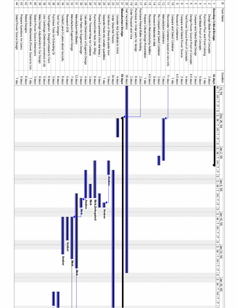
Appendix A: Gantt Chart
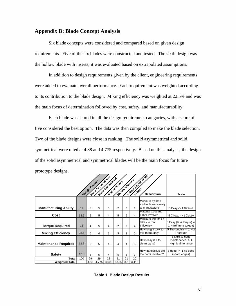
Appendix B: Blade Concept Analysis
Appendix C: Scale Reduction Testing
Appendix D: Power Source Concept Analysis
Appendix E: Procedure/Assembly
Appendix F: CAD Drawings
1
I. Team Member Assignments
Amber Beck: Team Leader
Midterm Presentation, Project Management, Gantt chart, Testing procedures, Final Paper
Nick Dalbec
Manufacturing Prototype, Bill of Materials, Project Budget, Cost Analysis, Testing
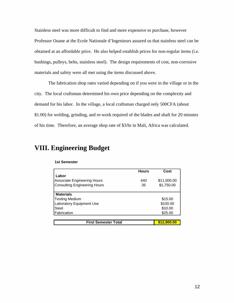
The first semester budget is broken down into two major parts: labor and
materials. The team consisted of four associated engineers, putting in ten hours a week
for eleven weeks. The salary was calculated at $25 per hour based on a $50,000 entry-
level engineer. Consulting hours consisted of Dr. George, Harry Gebbens, and contacts
from Shea Yeleen International. Their salary was estimated at $100,000 per year at $50
per hour.
14
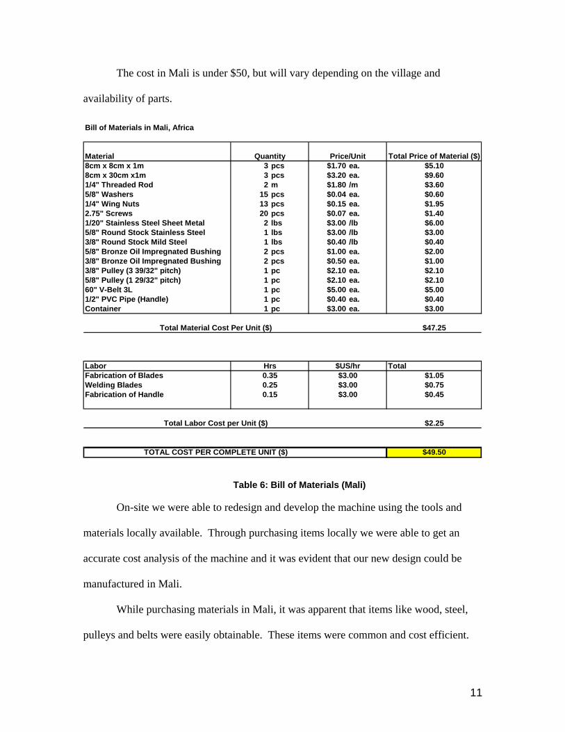
The materials purchased first semester consisted of parts for fabrication and shop
tools used. All other parts and components used for experimenting were accounted for.
The total cost for first semester was: $12,900.
The second semester and J-term budget consisted of everything except the March
trip to Africa. Three associate engineers remained on the team after first semester.
During J-term only two associates were able to work on prototype development and
testing. Associate hours for J-term and second semester totaled 252 hours. The total cost
for second semester and J-term was: $11,190.
The trip to Mali contributed to almost half of our budget. Three engineers and
one consulting engineer (Dr. George) were considered as part of the trip cost (tickets,
hotels, food) at $2,500 per person. Other expenditures were accounted for such as: travel
agencies, booking fees, materials, translators and preparations for departure. A $500
travel fee paid by each of the three associated engineers was also included in the budget
report. The total cost for the trip to Mali was: $24,550. The project total throughout the
entire year totaled to $48,640.
IX. Concept Generation
The method of mixing used by women in Mali is to mix by hand. Most often the
container holding the paste is placed on the ground, and women stand over the bucket and
bend at the waste. Not only is mixing by hand tiresome and time consuming, but the
bending can cause strain on the back, making the process only suitable for younger
women. In order to ensure an efficient development of all aspects of the project the
15
mixer was separated into three main components: blades, container, and power
source/transmission.
Blade Concept Designs
Proof of Concept Testing
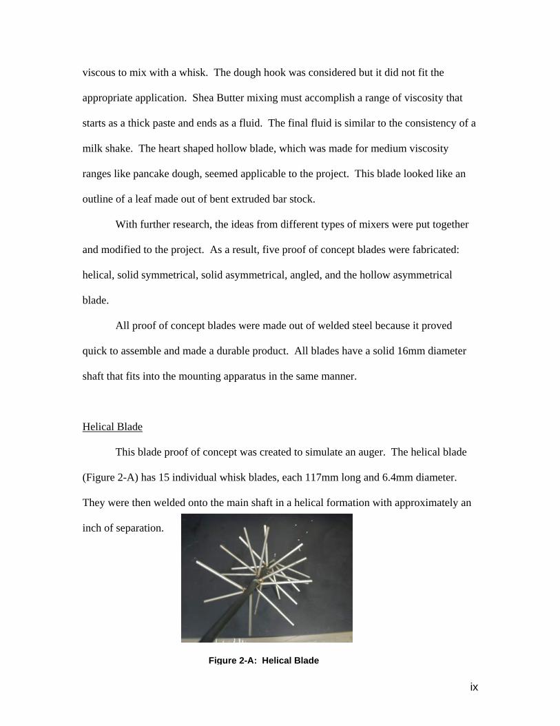
The first step in selecting a blade design was proof of concept testing. For this,
five different blade designs were constructed and tested by a visual inspection of mixing
food coloring into a mixture of flour and water. From this testing, the helical blade
inspired by an auger and the hollow blade inspired by kitchen mixers were found to be
inadequate. More information about blade selection can be found in Appendix B.
Scale Reduction Testing
During the months of January and February, more testing was performed. Scale
models of the three best performing blade designs from the proof of concept testing were
produced. This was done so that they could be tested with the limited supply of actual
shea paste that was available. After testing, it was found that the asymmetrical blades
were able to extract oil most efficiently. More information on scale reduction testing can
be found in Appendix C.
Power Source Concepts
There were two main power source concepts tested. A discussion of other power
source possibilities can be found in Appendix D.
16
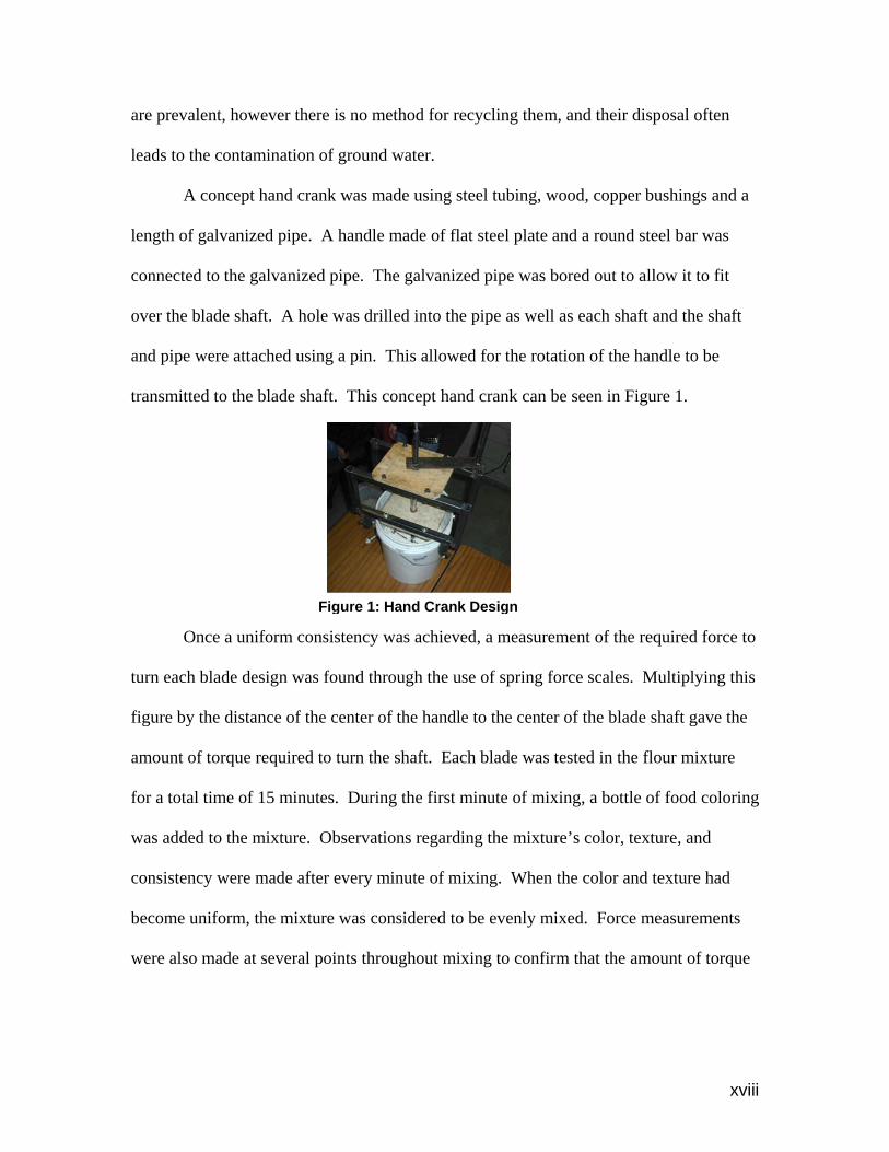
Hand Crank
The hand crank consists of an offset vertical shaft directly connected to the blade
via a horizontal link. It is a simple and effective way of rotating the shaft. One problem
is that it can be quite difficult to rotate the shaft.
Hand Bicycle
This idea was originally derived from a standard bicycle drive system. The
concept was adapted to a hand powered style to accommodate for the preferred range of
motion for the Malian women. The hand bicycle concept is composed of two handles on
opposite sides that rotate horizontally around a fixed point. A gear or pulley is placed
between these handles for the accompanying transmission of power. A gear ratio can
easily be applied to reduce the amount of energy required to turn the crank. This power
source can be manufactured simply through then bending of round bar. A person could
use one or both handles for manual power, or two people could use the opposing handle
to combine their efforts.
Transmission Concepts
The first concept was to use a set of bevel gears to transfer rotation of two shafts.
This concept can be seen in many mechanical systems. This idea was mainly thought of
by the examination of differentials in automobiles. Bevel gears are a very effective way
of transferring power however, they can also be costly. This concept was discarded.
The next transmission idea was that of a twisted belt around two perpendicular
shafts. This was an idea seen by the examination of vacuum cleaner transmission. Since
17
this concept is an effective way to transfer motion while still being cost effective, it was
selected to be used as a transmission.
Container Concepts
The concepts for a container came down to two different options; a plastic bucket
or a hand made bucket. One successful shea butter processing method in Ghana uses a
hexagonal container for shea butter mixing. Our contact claims that it is the hexagonal
shape of the container that is vital for the oil extraction4. The container is custom-made
out of stainless steel in order remain non-corrosive. Stainless steel is expensive and to
manufacture a hand made container would not be as simple as buying a plastic one.
Therefore, after results of testing revealed that that oil could in fact be extracted without
the hexagonal design, we selected the plastic container. This is explained more
thoroughly in the Testing section and in Appendix C.
X. Prototype Progression
From the different experiments and proof of concept studies performed, the
plastic bucket, angled asymmetrical blades, and a horizontal bicycle style hand crank
with a twisted belt transmission were the options chosen for our machine prototype.
Materials selected for the initial prototype were based upon the implied availability and
manufacturing capabilities in Africa. The machine developed on-site in Mali used
materials and manufacturing techniques found in local markets.
Failure with our second prototype during the initial testing phase in Mali proved
to be greatly beneficial for our product development.
18
Prototype Progression:
1st Prototype
Qualities:
• Proof of concept machine.
• Hand crank on 5 gallon bucket.
• Steel and wood frame.
Problems:
• Difficult to turn.
• No access to paste inside bucket.
2nd Prototype
Qualities:
• Wood beam on top of 5 gallon
bucket.
• Slotted wood crank frame.
• Two sided bicycle style hand
crank.
• Twisted belt.
• Bucket and crank frame separate from each other.
19
Problems:
• Very unstable.
• Difficult to keep belt in tension.
• Difficult to access contents of bucket.
• Crank tended to come out of slots.
• Wood beam was not anchored to bucket.
3rd Prototype
Qualities:
• One piece frame design.
• Wider plastic bucket.
• Threaded bar through wood plank to
anchor bucket.
• Two pieces of metal on either side of
threaded bar.
• One-handed crank.
• Longer, wider blades.
• Crank positioned by a hole in a vertical post.
Problems:
• Belt slipped after time.
• Somewhat difficult to turn.
• Two piece metal tension plates difficult to get into place.
20
• More suited for a left handed person.
• Bare metal crank uncomfortable on hand.
4th Prototype
Qualities:
• Addition of tensioning thread bar and block.
Problems:
• Somewhat difficult to turn.
• Two piece tension plates difficult to get
into place.
• More suited for left handed person.
• Bare metal crank uncomfortable on hand.
• Tension bar and block requires a vice grip
to fully tension.
5th Prototype
Qualities:
• Larger pulley on crank.
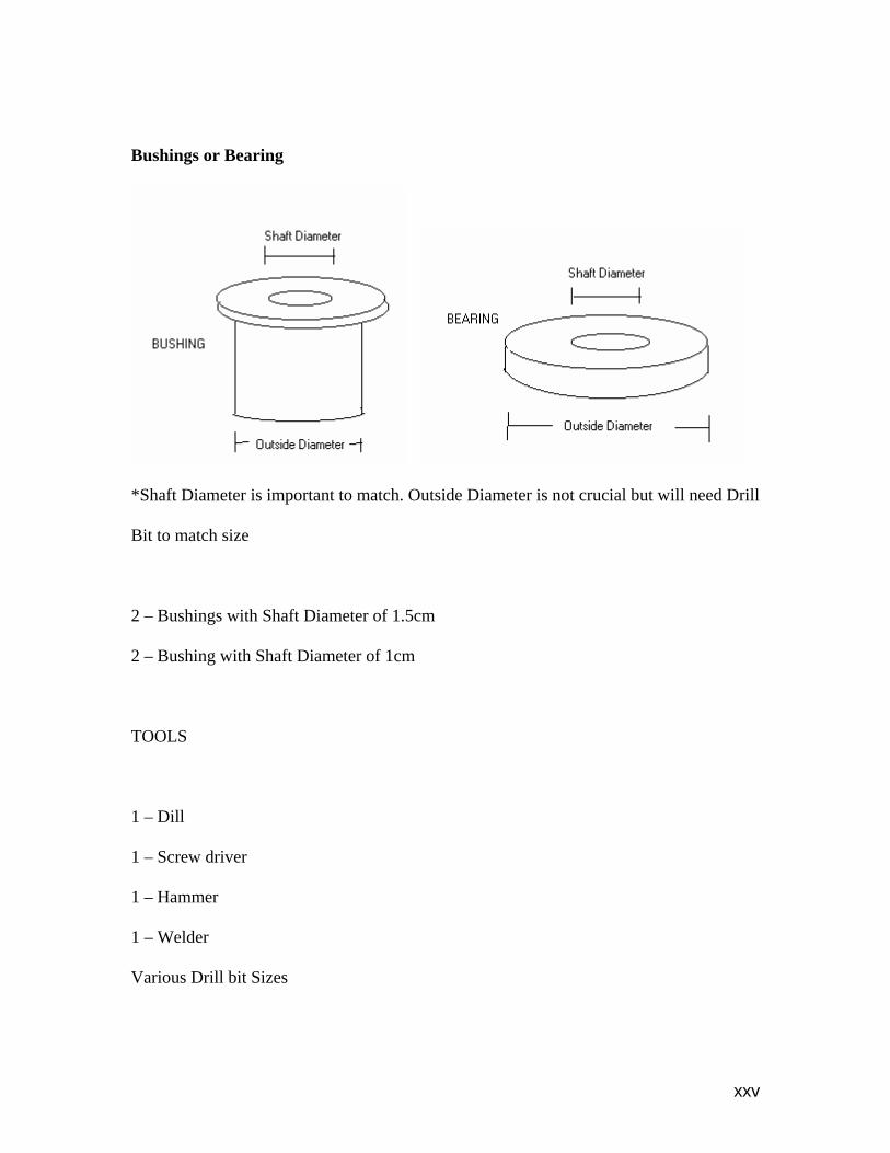
• Brass bushings placed in crank post.
• Plastic handle added to crank.
• Crank moved to opposite side.
• Tension thread bar incorporated into shaft beam.
21
• Single piece of metal with slot used for vertical tension bars.
• Drilled a hole in the post for tensioning bar and added a wing nut and washer
eliminating the need for a vice grip.
Problems:
• To produce the slot in the single piece of metal used to clamp down the container
may be difficult.
22
XI. Manufacturability
With limited availability of shop tools in the village, the final design of the
mixing machine requires minimal tools necessary for assembly. Wing-nuts are used to
reduce the need for special tools in assembling the machine. All other parts are either
hand-drilled or hand-tightened further eliminating the need for expensive tools. Screws
are used to secure wood fixtures and a screw-driver set was left in the village to ensure
the local Malians would have adequate tools for manufacturing the machine. Cutting
wood, drilling holes and alignment of parts were all done effortlessly by the local
Malians.
Welding will be completed by the local craftsmen. Working with the craftsman in
Mali, it was evident that his capabilities and skills were exceptional for the work required
to manufacture the blade assembly. Any failures or problems resulting from daily use of
the machine will be easily maintained and fixed in Mali.
XII. Testing Results
The objective of traveling to Mali was to test the mixer under real applications
and use. It was also critical to obtain user feedback to make adjustments and
improvements based on their comments. The first testing result was beneficial for the
group, providing us with crucial feedback from the local Malians. Our second and third
tests proved successful.
23
Test
LocationEnvironment
Conditions (in shade)
Time (min.) Paste Temp Paste Appearance
0 90.6 Oily, no foam present5 92
10
92.1
Removed container/blades from the base. Instability was laborious. Attached hand crank directly to blades and continued the experiment. Took observations of container and blade design.
20 89.525 Notice Oil in water
30 Stop and let mixture sit354550
60
88 Not as much foam as the woman get by hand
User Comments
Quantity of Shea Paste (approx.)
94.8 degrees F
10 pounds of paste
Design 1
Africa
Difficult to use, base not stable, more than one woman still required for processing, they wanted to try a wider bucket with wider blades, the size of their hands. Requested a machine they could sit at.
1st Prototype
70White foam was extracted
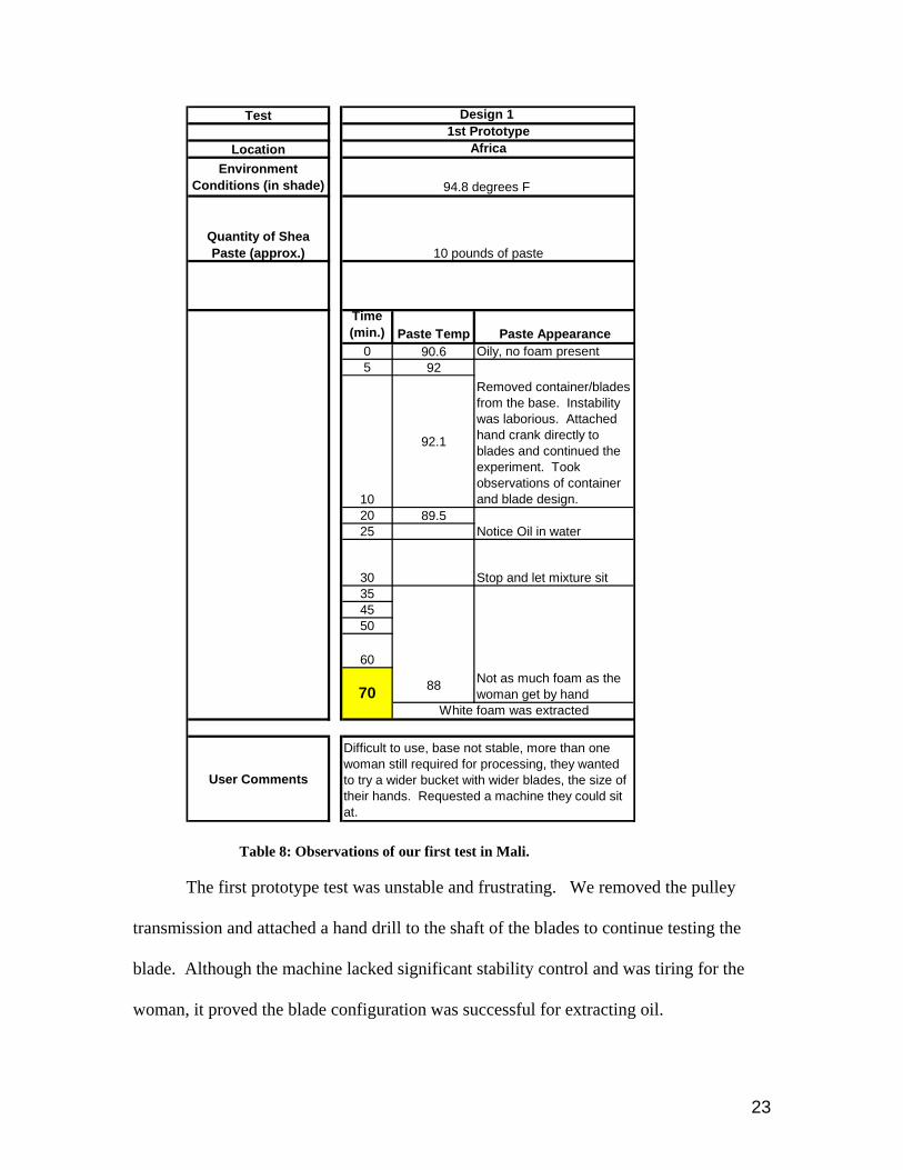
Table 8: Observations of our first test in Mali.
The first prototype test was unstable and frustrating. We removed the pulley
transmission and attached a hand drill to the shaft of the blades to continue testing the
blade. Although the machine lacked significant stability control and was tiring for the
woman, it proved the blade configuration was successful for extracting oil.
24
The machine design for the second test was significantly improved. The design
was simple, the range of motion was comfortable and the features of a hand crank were
more desirable. Successful results were obtained after just 58 minutes of mixing the
paste.
Table 9: Observations of the re-designed mixer in Mali.
Time Paste Appearance05
10
Added lots of water, approxim ately 2:1 water to paste ratio. Belt kept slipping, added a support board to keep belt in tension. Paste felt sticky, like gum .
2025
3035 W ater drop test45 Foam present, lighter in color50
55Added water to create better separation
96 degrees FDid not take tem p. readings of paste,
previous testing showed little to no significant changes in paste tem p.
Tested with 10 lbs. of paste
Design 2
Africa
Lots of oil and water splashed onto wood, could result in bacteria. Machine seem s m uch faster than working by hand. Requested the handle be placed on the right side of post.
O ily and m ore viscous com pared to test one
Bamako Prototype
58 W hite foam was extracted!
Can hear a thunking sound as paste hits wall of container. Paste started to feel oily and slide against the container.
Test
LocationEnvironment
Conditions (in shade)
User Comments
Quantity of Shea Paste (approx.)
25
The third test was conducted back at St. Thomas with our final redesigned
machine based off comments made by the local woman. After simulating the Malian
environment in a room at 85 degrees Fahrenheit, successful oil extraction was obtained
after just 30minutes of mixing.
Table 3: Observations of the final design testing in the United States
Time Paste Appearance05
10
20
25
Added more water
Design 3
United States
85 degrees F
5 pounds of nuts were crushed and resulted in close to 3 pounds of paste
Final Design
Warm water was added to the paste approximately 1:1 ratio paste to water. From Nigerian studies and experience in Africa we knew to add warm water (94 degrees) Results of Nigerian studies showed 3 parts water, but after adding one part to our paste we decided it would be best not to begin with that much. There was not a lot of paste to start with. After 10 minutes paste temp. was 84.6 African water drip test, WE COULD SEE OIL!!!
We predict they will like the more comfortable handle height, position on post and handle material. By using a larger pulley less force is required for use.
30 Successful white foam extraction!
Test
LocationEnvironment
Conditions (in shade)
User Comments
Quantity of Shea Paste (approx.)
26
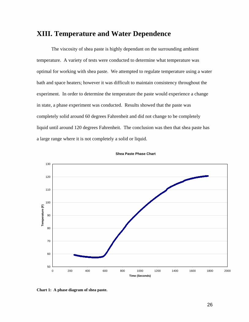
XIII. Temperature and Water Dependence
The viscosity of shea paste is highly dependant on the surrounding ambient
temperature. A variety of tests were conducted to determine what temperature was
optimal for working with shea paste. We attempted to regulate temperature using a water
bath and space heaters; however it was difficult to maintain consistency throughout the
experiment. In order to determine the temperature the paste would experience a change
in state, a phase experiment was conducted. Results showed that the paste was
completely solid around 60 degrees Fahrenheit and did not change to be completely
liquid until around 120 degrees Fahrenheit. The conclusion was then that shea paste has
a large range where it is not completely a solid or liquid.
Shea Paste Phase Chart
50
60
70
80
90
100
110
120
130
0 200 400 600 800 1000 1200 1400 1600 1800 2000
Time (Seconds)
Tem
pera
ture
(F)
Chart 1: A phase diagram of shea paste.
27
Attempts to determine the optimal testing temperature were unsuccessful. Using
information from www.weather.com, we found that average temperatures in Mali were
around 90 degrees Fahrenheit and decided to test in the temperature range from 85 – 95
degrees5. While in Mali, temperature was recorded regularly and it was then determined
that the temperature of the paste does not change much during processing. The average
temperature determined on-site in the shade was 98 degrees Fahrenheit and the average
temperature of well water added to the paste was 86 degrees.
Through experimenting at the Institue d’Economie (IER) observations of
processing was noted. The addition of refrigerated water was added to the paste in small
quantities. The experiment was not successful and while cleaning out the machine it was
observed that the paste had begun solidifying on the container, shaft and blades.
Therefore, when working with shea paste, cold water (below 70 degrees Fahrenheit)
should not be added. The temperature of the water being added affects the chemical
reaction taking place in the mixing process.
Upon returning to the United States a Nigerian Thesis on shea butter had arrived.
This proved useful in determining the optimal amount of water to add when extracting oil
from shea paste. The results of experiments discussed stated that three parts water to one
part paste is most advantageous6. After the oil begins to separate, more water can be
added without concern. Our experiments with the final design of the mixing machine
supported these results.
28
XIV. Final Design Evaluation
• The cost of the mixer meets the requirement at approximately $50.00 (in Mali).
• All parts in contact with shea paste are made of stainless steel or plastic.
• Disassembly is easy because it requires no tools.
o Wing nuts can be unscrewed allowing clamps to be removed easily.
o Shaft and shaft post are removed in one piece separating easily from
bucket. This allows for the easy cleaning of the mixer.
• The mixer can accommodate many different sized containers. The use of a wide
container allows for easy access to the paste.
• Rotating the crank at approximately 60 rpm causes oil extraction at approximately
30 minutes.
• Oil extraction ratio of 3:1 was maintained using the mixer.
• Operation of the mixer can be done by one woman.
o There is an option of sitting or standing while using the machine.
• Tensioning the belt only requires the turning of a wing nut.
Benefits/Features
The final design was intended to be flexible and easy to use. The most complex piece
of the design is the blades, which consists of three different lengths of stainless steel, all
8mm wide. They are welded onto the shaft at a 45 degree angle. Fabrication of the blade
design is within the production capabilities of villages. Other parts for the machine are
available in local markets. The design is adjustable so that different container sizes can
be used. Since the setup/disassembly of the mixer requires no tools, it is easy to use and
29
clean. Mixing time is greatly reduced and the larger bucket allows for greater batch sizes
of shea butter to be produced.
XV. Conclusions
Through research and experimentation the Mali Mixer team was able to develop a
successful prototype. Using feedback from the Malian women was vital for the final
design. User comfort was kept in mind for ease of use, range of motion, and the location
of the power source. The manually powered machine met all customer and engineering
design requirements. Using the mixer, the women in Mali were able to produce twice as
much shea butter with little to no physical strain. The final design was able to extract oil
in 30 minutes, greatly reducing the average mixing time. With reduced mixing time,
reduced physical strain and an increase in batch size, production of shea butter products
will increase.
The Mali Mixer team is optimistic for the future of this project. Shea Yeleen
International (SYI) will be able to disseminate the machine and educate the local village
women in how to form cooperatives and establish fair-trade. Using the assembly
instructions and drawings provided, SYI contacts will be able to teach people how to
build, maintain, and optimize production from the machine. With the increase of shea
butter production in the villages, women will be able to sell their products and create
more income for themselves. As SYI begins working with more and more women in
Mali, the establishment of fair-trade and the fight against poverty will be set in motion.
30
XVI. References
1. Wright, Rahama; Shea Yeleen International. 280 Madison Avenue,


![Manually Operated Metallic Gas Valves for Use in Gas ...files.asme.org/Catalog/Codes/PrintBook/33064.pdf · ASME B16.33-2012 [Revision of ASME B16.33-2002 (R2007)] Manually Operated](https://static.documents.pub/doc/80x56/5e4424a5514494245a4ad269/manually-operated-metallic-gas-valves-for-use-in-gas-filesasmeorgcatalogcodesprintbook33064pdf.jpg)


