1 Design of a Qi Wireless Charging Device A Guide to Engineering Considerations The Qi (pronounced Chee) wireless power transfer standard, based on the Wireless Power Consortium (WPC) Power Class 0 specification, has become the international wireless charging standard for consumer electronics devices. This specification defines two discrete power levels: the 5W (Baseline Power Profile) and the 15W (Extended Power Profile) which allows charging devices to easily adapt to changing power levels. This is important to ensure compatibility with different types of consumer electronics devices, such as smart- phones and tablets. Qi Wireless Design Overview: The principle of wireless power transfer in basic terms is an open-air transformer consist- ing of primary and secondary coils and associated electronics. The same concept applies; magnetic flux coupling occurs between the two coils which induces a voltage on the secondary coil. This white paper is intended to provide design engineers with a com- prehensive overview of the major components required to incorporate Qi wireless charging into consumer electronics products. Figure 1: Qi Charger Power and Data Transfer Block Diagram (Rohm, 2015) Tx Controller MOSFET Driver Transmitter (TX) Receiver (RX) Data Data Power Demod Half/Full Bridge Rectification Mod/Demod Voltage & Current Sensing Qi packet Controller PMA packet Controller LDO Load
Transcript
1
Design of a Qi Wireless Charging DeviceA Guide to Engineering Considerations
The Qi (pronounced Chee) wireless power transfer standard, based on the Wireless Power Consortium (WPC) Power Class 0 specification, has become the international wireless charging standard for consumer electronics devices. This specification defines two discrete power levels: the 5W (Baseline Power Profile) and the 15W (Extended Power Profile) which allows charging devices to easily adapt to changing power levels. This is important to ensure compatibility with different types of consumer electronics devices, such as smart-phones and tablets.
Qi Wireless Design Overview:
The principle of wireless power transfer in basic terms is an open-air transformer consist-ing of primary and secondary coils and associated electronics. The same concept applies; magnetic flux coupling occurs between the two coils which induces a voltage on the secondary coil.
As shown in Figure 1, a Qi Charger design consists of two subsystems: Transmitter (Tx) and the Receiver (Rx). The Tx subsystem is composed of integrated circuits (ICs) and a Tx coil that are used to convert a DC low voltage (5 to 20VDC) power source to an AC high voltage of 50 to 100VAC. This AC voltage is used to energize the Tx resonance tank circuit to create a tuned magnetic field frequency in the range of 100KHz to 120KHz.
The Qi wireless receiver (Rx) subsystem is also composed of a specific set of ICs, along with the Rx coil, that convert the magnetic field’s AC energy field back to DC power that can then be used to charge a battery and/or provide power directly to the Receiver load. The Receiver subsystem plays the most critical role in fine-tuning the power transfer efficiency which requires a combination of series and parallel capacitors that, along with the Rx coil, create a resonant LC tank circuit to match the Transmitter’s resonance frequency.
As shown in Figure 2, the Receiver includes a dual resonant circuit that consists of the secondary coil LRX along with series CS and parallel Cd capacitances. The purpose of the series resonant capacitor CS is to maximize power transfer efficiency. The parallel capacitor Cd is used to enhance resonant detection. The mutual inductance Lm(k) (flux linkage between the two coils) is dependent on the Tx and Rx coils’ electrical properties and on the physical separation of the two coils (Smith, 2017). The Receiver’s rectification circuit provides full-wave rectification of the AC waveform and an output smoothing function. The output of the rectification circuit provides power to the load and to the communications and control units which execute the power control algorithms. The TX resonant network LTX and CP converts the AC square wave to a sinusoidal waveform which allows the power FETS to operate in a soft switching mode as well as improves power transfer efficiency and reduces EMI harmonic radiation.
Before the Tx charging device can begin power transfer, it outputs a ‘search’ pulse signal (ping) of energy to determine if there is a Qi-compliant receiver device within close proximi-ty (2 -> 6mm). Once it detects a receiver, the transmitter then provides a small amount of power to the receiver so the receiver can communicate back to the transmitter its power requirements. Once this handshake is complete, the transmitter starts sending the request-ed power to the receiver. During power transfer, the receiver is continually communicating with the receiver with power request updates. This process ensures that the receiver’s
This white paper is intended to provide design engineers with a com-prehensive overview of the major components required to incorporate Qi wireless charging into consumer electronics products.
Figure 1: Qi Charger Power and Data Transfer Block Diagram (Rohm, 2015)
TxController
MOSFETDriver
Transmitter (TX)
Receiver (RX)
Data
Data
Power
Demod
Half/FullBridge
RectificationMod/Demod
Voltage &CurrentSensing
Qi packetController
PMA packetController
LDO Load
2
The Qi (pronounced Chee) wireless power transfer standard, based on the Wireless Power Consortium (WPC) Power Class 0 specification, has become the international wireless charging standard for consumer electronics devices. This specification defines two discrete power levels: the 5W (Baseline Power Profile) and the 15W (Extended Power Profile) which allows charging devices to easily adapt to changing power levels. This is important to ensure compatibility with different types of consumer electronics devices, such as smart-phones and tablets.
Qi Wireless Design Overview:
The principle of wireless power transfer in basic terms is an open-air transformer consist-ing of primary and secondary coils and associated electronics. The same concept applies; magnetic flux coupling occurs between the two coils which induces a voltage on the secondary coil.
As shown in Figure 1, a Qi Charger design consists of two subsystems: Transmitter (Tx) and the Receiver (Rx). The Tx subsystem is composed of integrated circuits (ICs) and a Tx coil that are used to convert a DC low voltage (5 to 20VDC) power source to an AC high voltage of 50 to 100VAC. This AC voltage is used to energize the Tx resonance tank circuit to create a tuned magnetic field frequency in the range of 100KHz to 120KHz.
The Qi wireless receiver (Rx) subsystem is also composed of a specific set of ICs, along with the Rx coil, that convert the magnetic field’s AC energy field back to DC power that can then be used to charge a battery and/or provide power directly to the Receiver load. The Receiver subsystem plays the most critical role in fine-tuning the power transfer efficiency which requires a combination of series and parallel capacitors that, along with the Rx coil, create a resonant LC tank circuit to match the Transmitter’s resonance frequency.
As shown in Figure 2, the Receiver includes a dual resonant circuit that consists of the secondary coil LRX along with series CS and parallel Cd capacitances. The purpose of the series resonant capacitor CS is to maximize power transfer efficiency. The parallel capacitor Cd is used to enhance resonant detection. The mutual inductance Lm(k) (flux linkage between the two coils) is dependent on the Tx and Rx coils’ electrical properties and on the physical separation of the two coils (Smith, 2017). The Receiver’s rectification circuit provides full-wave rectification of the AC waveform and an output smoothing function. The output of the rectification circuit provides power to the load and to the communications and control units which execute the power control algorithms. The TX resonant network LTX and CP converts the AC square wave to a sinusoidal waveform which allows the power FETS to operate in a soft switching mode as well as improves power transfer efficiency and reduces EMI harmonic radiation.
Before the Tx charging device can begin power transfer, it outputs a ‘search’ pulse signal (ping) of energy to determine if there is a Qi-compliant receiver device within close proximi-ty (2 -> 6mm). Once it detects a receiver, the transmitter then provides a small amount of power to the receiver so the receiver can communicate back to the transmitter its power requirements. Once this handshake is complete, the transmitter starts sending the request-ed power to the receiver. During power transfer, the receiver is continually communicating with the receiver with power request updates. This process ensures that the receiver’s
The Qi (pronounced Chee) wireless power transfer standard, based on the Wireless Power Consortium (WPC) Power Class 0 specification, has become the international wireless charging standard for consumer electronics devices. This specification defines two discrete power levels: the 5W (Baseline Power Profile) and the 15W (Extended Power Profile) which allows charging devices to easily adapt to changing power levels. This is important to ensure compatibility with different types of consumer electronics devices, such as smart-phones and tablets.
Qi Wireless Design Overview:
The principle of wireless power transfer in basic terms is an open-air transformer consist-ing of primary and secondary coils and associated electronics. The same concept applies; magnetic flux coupling occurs between the two coils which induces a voltage on the secondary coil.
As shown in Figure 1, a Qi Charger design consists of two subsystems: Transmitter (Tx) and the Receiver (Rx). The Tx subsystem is composed of integrated circuits (ICs) and a Tx coil that are used to convert a DC low voltage (5 to 20VDC) power source to an AC high voltage of 50 to 100VAC. This AC voltage is used to energize the Tx resonance tank circuit to create a tuned magnetic field frequency in the range of 100KHz to 120KHz.
The Qi wireless receiver (Rx) subsystem is also composed of a specific set of ICs, along with the Rx coil, that convert the magnetic field’s AC energy field back to DC power that can then be used to charge a battery and/or provide power directly to the Receiver load. The Receiver subsystem plays the most critical role in fine-tuning the power transfer efficiency which requires a combination of series and parallel capacitors that, along with the Rx coil, create a resonant LC tank circuit to match the Transmitter’s resonance frequency.
3
changing load requirements are supported with the correct amount of power required at any point in time. How Qi Wireless Power Transfer Works:
The basic physical principle supporting Qi wireless power transfer is called magnetic induc-tion, where flux lines generated from a time-varying magnetic field (~120KHz) within the Transmitter coil creates an electromotive force that produces a voltage across the terminals of the Receiver coil located inside the portable device. Key to wireless power transfer is the fact that a magnetic field can penetrate through any non-metallic, non-ferrous materials. This allows for significant flexibility in the design of both the charger base and the portable device.
As shown in Figure 1, Qi-based power transfer requires bidirectional communications between the Transmitter and Receiver subsystems. In order to set up power transfer and respond to changing load conditions, the transmitter and receiver execute a communication protocol with each other (WPC, 2017). The Qi power transmitter uses a modulation scheme called frequency shift keying (FSK) to provide communications for power transfer synchroni-zation with the receiver. The receiver uses a different modulation scheme called amplitude shift keying (ASK) to communicate power level requests back to the transmitter. The actual wireless power transfer occurs when the alternating current in the transmitter coil induces an AC voltage in the receiver coil by a process known as magnetic induction. The receiver subsystem incorporates an AC-to-DC full bridge rectifier to create a DC voltage output, along with a Qi packet controller for communications back to the transmitter.
As shown in Figure 2, the Receiver includes a dual resonant circuit that consists of the secondary coil LRX along with series CS and parallel Cd capacitances. The purpose of the series resonant capacitor CS is to maximize power transfer efficiency. The parallel capacitor Cd is used to enhance resonant detection. The mutual inductance Lm(k) (flux linkage between the two coils) is dependent on the Tx and Rx coils’ electrical properties and on the physical separation of the two coils (Smith, 2017). The Receiver’s rectification circuit provides full-wave rectification of the AC waveform and an output smoothing function. The output of the rectification circuit provides power to the load and to the communications and control units which execute the power control algorithms. The TX resonant network LTX and CP converts the AC square wave to a sinusoidal waveform which allows the power FETS to operate in a soft switching mode as well as improves power transfer efficiency and reduces EMI harmonic radiation.
Before the Tx charging device can begin power transfer, it outputs a ‘search’ pulse signal (ping) of energy to determine if there is a Qi-compliant receiver device within close proximi-ty (2 -> 6mm). Once it detects a receiver, the transmitter then provides a small amount of power to the receiver so the receiver can communicate back to the transmitter its power requirements. Once this handshake is complete, the transmitter starts sending the request-ed power to the receiver. During power transfer, the receiver is continually communicating with the receiver with power request updates. This process ensures that the receiver’s Figure 3: Qi Tx-Rx Power Transfer and Communications State Machine (Microchip, 2017)
SELECTION0
PING1
ID &CONFIGURATION
2
NEGOTIATION4
RENEGOTIATION6
RENEGOTIATIONREQUEST
POWERTRANSFER
3
PI CONTROLLOOP
Full-Bridge
Half-Bridge
Load ≤5W0W < Load ≤ 15W
START
NEGOTIATIONCOMPLETED
POWER TRANSFERCOMPLETE OR ERRORCONDITION
RENEGOTIATE DEFAULTPOWER CONTRACTP > 5WNEG = ONE
NEGOTIATION FAILURE OR ERRORCONDITION
CALIBRATION FAILURE OR ERROR CONDITION
RECEIVER IS FIRSTPLACED ON THE BASE STATION
NO RESPONSE ORNO POWERNEEDED
ERRORCONDITION
OBJECTDETECTED
NEGOTIATION SUCCESSFUL
NO NEGOTIATION REQUESTED: NEG = ZERO(5W POWER RECEIVERS ONLY)
CALIBRATIONSUCCESSFUL
CALIBRATION5
The Qi (pronounced Chee) wireless power transfer standard, based on the Wireless Power Consortium (WPC) Power Class 0 specification, has become the international wireless charging standard for consumer electronics devices. This specification defines two discrete power levels: the 5W (Baseline Power Profile) and the 15W (Extended Power Profile) which allows charging devices to easily adapt to changing power levels. This is important to ensure compatibility with different types of consumer electronics devices, such as smart-phones and tablets.
Qi Wireless Design Overview:
The principle of wireless power transfer in basic terms is an open-air transformer consist-ing of primary and secondary coils and associated electronics. The same concept applies; magnetic flux coupling occurs between the two coils which induces a voltage on the secondary coil.
As shown in Figure 1, a Qi Charger design consists of two subsystems: Transmitter (Tx) and the Receiver (Rx). The Tx subsystem is composed of integrated circuits (ICs) and a Tx coil that are used to convert a DC low voltage (5 to 20VDC) power source to an AC high voltage of 50 to 100VAC. This AC voltage is used to energize the Tx resonance tank circuit to create a tuned magnetic field frequency in the range of 100KHz to 120KHz.
The Qi wireless receiver (Rx) subsystem is also composed of a specific set of ICs, along with the Rx coil, that convert the magnetic field’s AC energy field back to DC power that can then be used to charge a battery and/or provide power directly to the Receiver load. The Receiver subsystem plays the most critical role in fine-tuning the power transfer efficiency which requires a combination of series and parallel capacitors that, along with the Rx coil, create a resonant LC tank circuit to match the Transmitter’s resonance frequency.
4
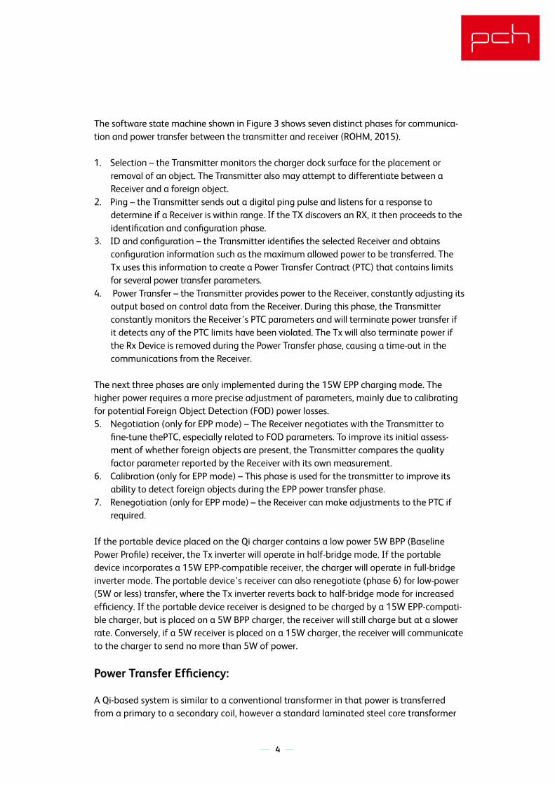
The software state machine shown in Figure 3 shows seven distinct phases for communica-tion and power transfer between the transmitter and receiver (ROHM, 2015).
1. Selection – the Transmitter monitors the charger dock surface for the placement or removal of an object. The Transmitter also may attempt to differentiate between a Receiver and a foreign object.
2. Ping – the Transmitter sends out a digital ping pulse and listens for a response to determine if a Receiver is within range. If the TX discovers an RX, it then proceeds to the identification and configuration phase.
3. ID and configuration – the Transmitter identifies the selected Receiver and obtains configuration information such as the maximum allowed power to be transferred. The Tx uses this information to create a Power Transfer Contract (PTC) that contains limits for several power transfer parameters.
4. Power Transfer – the Transmitter provides power to the Receiver, constantly adjusting its output based on control data from the Receiver. During this phase, the Transmitter constantly monitors the Receiver’s PTC parameters and will terminate power transfer if it detects any of the PTC limits have been violated. The Tx will also terminate power if the Rx Device is removed during the Power Transfer phase, causing a time-out in the communications from the Receiver.
The next three phases are only implemented during the 15W EPP charging mode. The higher power requires a more precise adjustment of parameters, mainly due to calibrating for potential Foreign Object Detection (FOD) power losses.5. Negotiation (only for EPP mode) – The Receiver negotiates with the Transmitter to
fine-tune thePTC, especially related to FOD parameters. To improve its initial assess-ment of whether foreign objects are present, the Transmitter compares the quality factor parameter reported by the Receiver with its own measurement.
6. Calibration (only for EPP mode) – This phase is used for the transmitter to improve its ability to detect foreign objects during the EPP power transfer phase.
7. Renegotiation (only for EPP mode) – the Receiver can make adjustments to the PTC if required.
If the portable device placed on the Qi charger contains a low power 5W BPP (Baseline Power Profile) receiver, the Tx inverter will operate in half-bridge mode. If the portable device incorporates a 15W EPP-compatible receiver, the charger will operate in full-bridge inverter mode. The portable device’s receiver can also renegotiate (phase 6) for low-power (5W or less) transfer, where the Tx inverter reverts back to half-bridge mode for increased efficiency. If the portable device receiver is designed to be charged by a 15W EPP-compati-ble charger, but is placed on a 5W BPP charger, the receiver will still charge but at a slower rate. Conversely, if a 5W receiver is placed on a 15W charger, the receiver will communicate to the charger to send no more than 5W of power.
Power Transfer Efficiency:
A Qi-based system is similar to a conventional transformer in that power is transferred from a primary to a secondary coil, however a standard laminated steel core transformer
As shown in Figure 2, the Receiver includes a dual resonant circuit that consists of the secondary coil LRX along with series CS and parallel Cd capacitances. The purpose of the series resonant capacitor CS is to maximize power transfer efficiency. The parallel capacitor Cd is used to enhance resonant detection. The mutual inductance Lm(k) (flux linkage between the two coils) is dependent on the Tx and Rx coils’ electrical properties and on the physical separation of the two coils (Smith, 2017). The Receiver’s rectification circuit provides full-wave rectification of the AC waveform and an output smoothing function. The output of the rectification circuit provides power to the load and to the communications and control units which execute the power control algorithms. The TX resonant network LTX and CP converts the AC square wave to a sinusoidal waveform which allows the power FETS to operate in a soft switching mode as well as improves power transfer efficiency and reduces EMI harmonic radiation.
Before the Tx charging device can begin power transfer, it outputs a ‘search’ pulse signal (ping) of energy to determine if there is a Qi-compliant receiver device within close proximi-ty (2 -> 6mm). Once it detects a receiver, the transmitter then provides a small amount of power to the receiver so the receiver can communicate back to the transmitter its power requirements. Once this handshake is complete, the transmitter starts sending the request-ed power to the receiver. During power transfer, the receiver is continually communicating with the receiver with power request updates. This process ensures that the receiver’s
The Qi (pronounced Chee) wireless power transfer standard, based on the Wireless Power Consortium (WPC) Power Class 0 specification, has become the international wireless charging standard for consumer electronics devices. This specification defines two discrete power levels: the 5W (Baseline Power Profile) and the 15W (Extended Power Profile) which allows charging devices to easily adapt to changing power levels. This is important to ensure compatibility with different types of consumer electronics devices, such as smart-phones and tablets.
Qi Wireless Design Overview:
The principle of wireless power transfer in basic terms is an open-air transformer consist-ing of primary and secondary coils and associated electronics. The same concept applies; magnetic flux coupling occurs between the two coils which induces a voltage on the secondary coil.
As shown in Figure 1, a Qi Charger design consists of two subsystems: Transmitter (Tx) and the Receiver (Rx). The Tx subsystem is composed of integrated circuits (ICs) and a Tx coil that are used to convert a DC low voltage (5 to 20VDC) power source to an AC high voltage of 50 to 100VAC. This AC voltage is used to energize the Tx resonance tank circuit to create a tuned magnetic field frequency in the range of 100KHz to 120KHz.
The Qi wireless receiver (Rx) subsystem is also composed of a specific set of ICs, along with the Rx coil, that convert the magnetic field’s AC energy field back to DC power that can then be used to charge a battery and/or provide power directly to the Receiver load. The Receiver subsystem plays the most critical role in fine-tuning the power transfer efficiency which requires a combination of series and parallel capacitors that, along with the Rx coil, create a resonant LC tank circuit to match the Transmitter’s resonance frequency.
As shown in Figure 2, the Receiver includes a dual resonant circuit that consists of the secondary coil LRX along with series CS and parallel Cd capacitances. The purpose of the series resonant capacitor CS is to maximize power transfer efficiency. The parallel capacitor Cd is used to enhance resonant detection. The mutual inductance Lm(k) (flux linkage between the two coils) is dependent on the Tx and Rx coils’ electrical properties and on the physical separation of the two coils (Smith, 2017). The Receiver’s rectification circuit provides full-wave rectification of the AC waveform and an output smoothing function. The output of the rectification circuit provides power to the load and to the communications and control units which execute the power control algorithms. The TX resonant network LTX and CP converts the AC square wave to a sinusoidal waveform which allows the power FETS to operate in a soft switching mode as well as improves power transfer efficiency and reduces EMI harmonic radiation.
Before the Tx charging device can begin power transfer, it outputs a ‘search’ pulse signal (ping) of energy to determine if there is a Qi-compliant receiver device within close proximi-ty (2 -> 6mm). Once it detects a receiver, the transmitter then provides a small amount of power to the receiver so the receiver can communicate back to the transmitter its power requirements. Once this handshake is complete, the transmitter starts sending the request-ed power to the receiver. During power transfer, the receiver is continually communicating with the receiver with power request updates. This process ensures that the receiver’s
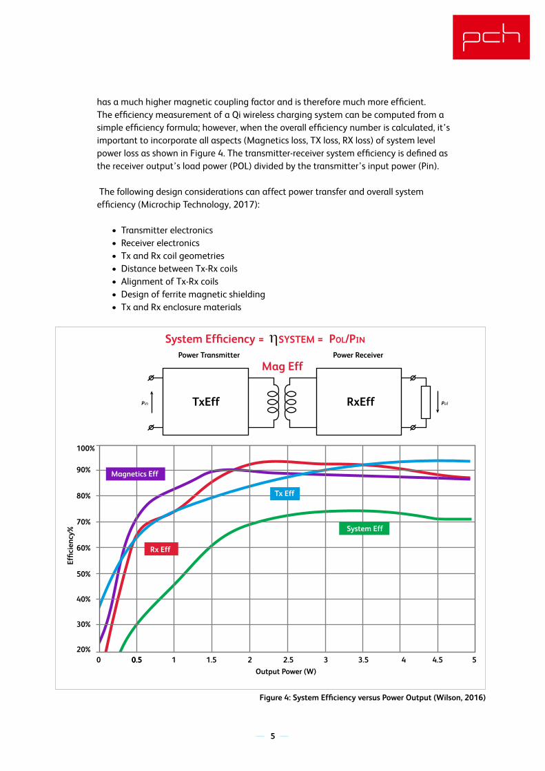
has a much higher magnetic coupling factor and is therefore much more efficient.The efficiency measurement of a Qi wireless charging system can be computed from a simple efficiency formula; however, when the overall efficiency number is calculated, it’s important to incorporate all aspects (Magnetics loss, TX loss, RX loss) of system level power loss as shown in Figure 4. The transmitter-receiver system efficiency is defined as the receiver output’s load power (POL) divided by the transmitter’s input power (Pin).
The following design considerations can affect power transfer and overall system efficiency (Microchip Technology, 2017):
• Transmitter electronics • Receiver electronics • Tx and Rx coil geometries• Distance between Tx-Rx coils• Alignment of Tx-Rx coils• Design of ferrite magnetic shielding• Tx and Rx enclosure materials
5
Figure 4: System Efficiency versus Power Output (Wilson, 2016)
020%
30%
40%
Effic
ienc
y%
Output Power (W)
Power Transmitter Power Receiver
50%
60%
70%
80%
90%
100%
Pin Pol
0.50.5 1 1.5 2 2.5 3 3.5 4 4.5 5
System Efficiency = SYSTEM = POL/PIN
Mag Eff
TxEff RxEff
Magnetics Eff
Tx Eff
Rx Eff
System Eff
The Qi (pronounced Chee) wireless power transfer standard, based on the Wireless Power Consortium (WPC) Power Class 0 specification, has become the international wireless charging standard for consumer electronics devices. This specification defines two discrete power levels: the 5W (Baseline Power Profile) and the 15W (Extended Power Profile) which allows charging devices to easily adapt to changing power levels. This is important to ensure compatibility with different types of consumer electronics devices, such as smart-phones and tablets.
Qi Wireless Design Overview:
The principle of wireless power transfer in basic terms is an open-air transformer consist-ing of primary and secondary coils and associated electronics. The same concept applies; magnetic flux coupling occurs between the two coils which induces a voltage on the secondary coil.
As shown in Figure 1, a Qi Charger design consists of two subsystems: Transmitter (Tx) and the Receiver (Rx). The Tx subsystem is composed of integrated circuits (ICs) and a Tx coil that are used to convert a DC low voltage (5 to 20VDC) power source to an AC high voltage of 50 to 100VAC. This AC voltage is used to energize the Tx resonance tank circuit to create a tuned magnetic field frequency in the range of 100KHz to 120KHz.
The Qi wireless receiver (Rx) subsystem is also composed of a specific set of ICs, along with the Rx coil, that convert the magnetic field’s AC energy field back to DC power that can then be used to charge a battery and/or provide power directly to the Receiver load. The Receiver subsystem plays the most critical role in fine-tuning the power transfer efficiency which requires a combination of series and parallel capacitors that, along with the Rx coil, create a resonant LC tank circuit to match the Transmitter’s resonance frequency.
6
As shown in Figure 2, the Receiver includes a dual resonant circuit that consists of the secondary coil LRX along with series CS and parallel Cd capacitances. The purpose of the series resonant capacitor CS is to maximize power transfer efficiency. The parallel capacitor Cd is used to enhance resonant detection. The mutual inductance Lm(k) (flux linkage between the two coils) is dependent on the Tx and Rx coils’ electrical properties and on the physical separation of the two coils (Smith, 2017). The Receiver’s rectification circuit provides full-wave rectification of the AC waveform and an output smoothing function. The output of the rectification circuit provides power to the load and to the communications and control units which execute the power control algorithms. The TX resonant network LTX and CP converts the AC square wave to a sinusoidal waveform which allows the power FETS to operate in a soft switching mode as well as improves power transfer efficiency and reduces EMI harmonic radiation.
Before the Tx charging device can begin power transfer, it outputs a ‘search’ pulse signal (ping) of energy to determine if there is a Qi-compliant receiver device within close proximi-ty (2 -> 6mm). Once it detects a receiver, the transmitter then provides a small amount of power to the receiver so the receiver can communicate back to the transmitter its power requirements. Once this handshake is complete, the transmitter starts sending the request-ed power to the receiver. During power transfer, the receiver is continually communicating with the receiver with power request updates. This process ensures that the receiver’s
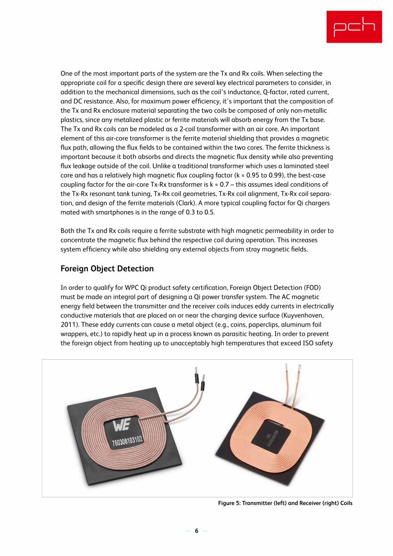
One of the most important parts of the system are the Tx and Rx coils. When selecting the appropriate coil for a specific design there are several key electrical parameters to consider, in addition to the mechanical dimensions, such as the coil’s inductance, Q-factor, rated current, and DC resistance. Also, for maximum power efficiency, it’s important that the composition of the Tx and Rx enclosure material separating the two coils be composed of only non-metallic plastics, since any metalized plastic or ferrite materials will absorb energy from the Tx base.The Tx and Rx coils can be modeled as a 2-coil transformer with an air core. An important element of this air-core transformer is the ferrite material shielding that provides a magnetic flux path, allowing the flux fields to be contained within the two cores. The ferrite thickness is important because it both absorbs and directs the magnetic flux density while also preventing flux leakage outside of the coil. Unlike a traditional transformer which uses a laminated steel core and has a relatively high magnetic flux coupling factor (k = 0.95 to 0.99), the best-case coupling factor for the air-core Tx-Rx transformer is k = 0.7 – this assumes ideal conditions of the Tx-Rx resonant tank tuning, Tx-Rx coil geometries, Tx-Rx coil alignment, Tx-Rx coil separa-tion, and design of the ferrite materials (Clark). A more typical coupling factor for Qi chargers mated with smartphones is in the range of 0.3 to 0.5. Both the Tx and Rx coils require a ferrite substrate with high magnetic permeability in order to concentrate the magnetic flux behind the respective coil during operation. This increases system efficiency while also shielding any external objects from stray magnetic fields.
Foreign Object Detection
In order to qualify for WPC Qi product safety certification, Foreign Object Detection (FOD) must be made an integral part of designing a Qi power transfer system. The AC magnetic energy field between the transmitter and the receiver coils induces eddy currents in electrically conductive materials that are placed on or near the charging device surface (Kuyvenhoven, 2011). These eddy currents can cause a metal object (e.g., coins, paperclips, aluminum foil wrappers, etc.) to rapidly heat up in a process known as parasitic heating. In order to prevent the foreign object from heating up to unacceptably high temperatures that exceed ISO safety
Figure 5: Transmitter (left) and Receiver (right) Coils
The Qi (pronounced Chee) wireless power transfer standard, based on the Wireless Power Consortium (WPC) Power Class 0 specification, has become the international wireless charging standard for consumer electronics devices. This specification defines two discrete power levels: the 5W (Baseline Power Profile) and the 15W (Extended Power Profile) which allows charging devices to easily adapt to changing power levels. This is important to ensure compatibility with different types of consumer electronics devices, such as smart-phones and tablets.
Qi Wireless Design Overview:
The principle of wireless power transfer in basic terms is an open-air transformer consist-ing of primary and secondary coils and associated electronics. The same concept applies; magnetic flux coupling occurs between the two coils which induces a voltage on the secondary coil.
As shown in Figure 1, a Qi Charger design consists of two subsystems: Transmitter (Tx) and the Receiver (Rx). The Tx subsystem is composed of integrated circuits (ICs) and a Tx coil that are used to convert a DC low voltage (5 to 20VDC) power source to an AC high voltage of 50 to 100VAC. This AC voltage is used to energize the Tx resonance tank circuit to create a tuned magnetic field frequency in the range of 100KHz to 120KHz.
The Qi wireless receiver (Rx) subsystem is also composed of a specific set of ICs, along with the Rx coil, that convert the magnetic field’s AC energy field back to DC power that can then be used to charge a battery and/or provide power directly to the Receiver load. The Receiver subsystem plays the most critical role in fine-tuning the power transfer efficiency which requires a combination of series and parallel capacitors that, along with the Rx coil, create a resonant LC tank circuit to match the Transmitter’s resonance frequency.
7
As shown in Figure 2, the Receiver includes a dual resonant circuit that consists of the secondary coil LRX along with series CS and parallel Cd capacitances. The purpose of the series resonant capacitor CS is to maximize power transfer efficiency. The parallel capacitor Cd is used to enhance resonant detection. The mutual inductance Lm(k) (flux linkage between the two coils) is dependent on the Tx and Rx coils’ electrical properties and on the physical separation of the two coils (Smith, 2017). The Receiver’s rectification circuit provides full-wave rectification of the AC waveform and an output smoothing function. The output of the rectification circuit provides power to the load and to the communications and control units which execute the power control algorithms. The TX resonant network LTX and CP converts the AC square wave to a sinusoidal waveform which allows the power FETS to operate in a soft switching mode as well as improves power transfer efficiency and reduces EMI harmonic radiation.
Before the Tx charging device can begin power transfer, it outputs a ‘search’ pulse signal (ping) of energy to determine if there is a Qi-compliant receiver device within close proximi-ty (2 -> 6mm). Once it detects a receiver, the transmitter then provides a small amount of power to the receiver so the receiver can communicate back to the transmitter its power requirements. Once this handshake is complete, the transmitter starts sending the request-ed power to the receiver. During power transfer, the receiver is continually communicating with the receiver with power request updates. This process ensures that the receiver’s
standard levels, the charging device must be capable of detecting the presence of foreign objects and take appropriate action to shut down power transfer.
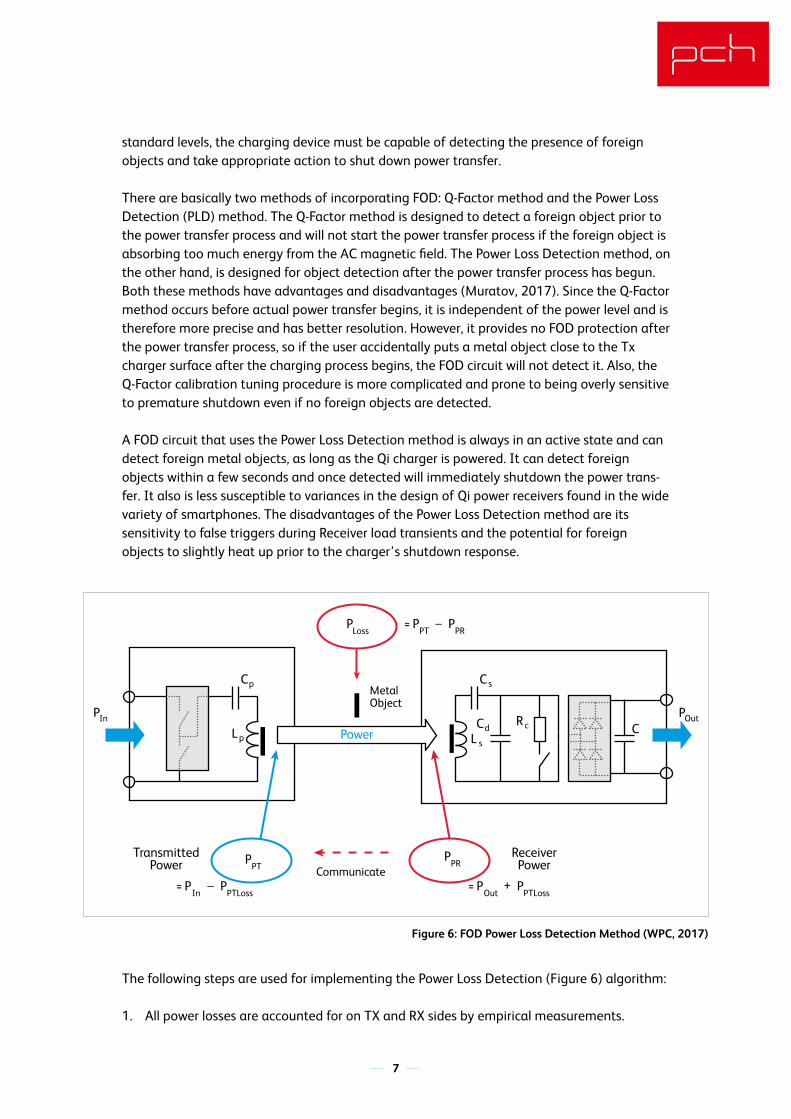
There are basically two methods of incorporating FOD: Q-Factor method and the Power Loss Detection (PLD) method. The Q-Factor method is designed to detect a foreign object prior to the power transfer process and will not start the power transfer process if the foreign object is absorbing too much energy from the AC magnetic field. The Power Loss Detection method, on the other hand, is designed for object detection after the power transfer process has begun.Both these methods have advantages and disadvantages (Muratov, 2017). Since the Q-Factor method occurs before actual power transfer begins, it is independent of the power level and is therefore more precise and has better resolution. However, it provides no FOD protection after the power transfer process, so if the user accidentally puts a metal object close to the Tx charger surface after the charging process begins, the FOD circuit will not detect it. Also, the Q-Factor calibration tuning procedure is more complicated and prone to being overly sensitive to premature shutdown even if no foreign objects are detected. A FOD circuit that uses the Power Loss Detection method is always in an active state and can detect foreign metal objects, as long as the Qi charger is powered. It can detect foreign objects within a few seconds and once detected will immediately shutdown the power trans-fer. It also is less susceptible to variances in the design of Qi power receivers found in the wide variety of smartphones. The disadvantages of the Power Loss Detection method are its sensitivity to false triggers during Receiver load transients and the potential for foreign objects to slightly heat up prior to the charger’s shutdown response.
The following steps are used for implementing the Power Loss Detection (Figure 6) algorithm:
1. All power losses are accounted for on TX and RX sides by empirical measurements.
Figure 6: FOD Power Loss Detection Method (WPC, 2017)
Power
P
TransmittedPower
ReceiverPowerCommunicate
OutPIn
PLoss
P= _PT
PPT
Cp Cs
C CdRc
L p L s
PPR
P= _In
PPTLoss
P= +Out
PPTLoss
PPR
MetalObject
The Qi (pronounced Chee) wireless power transfer standard, based on the Wireless Power Consortium (WPC) Power Class 0 specification, has become the international wireless charging standard for consumer electronics devices. This specification defines two discrete power levels: the 5W (Baseline Power Profile) and the 15W (Extended Power Profile) which allows charging devices to easily adapt to changing power levels. This is important to ensure compatibility with different types of consumer electronics devices, such as smart-phones and tablets.
Qi Wireless Design Overview:
The principle of wireless power transfer in basic terms is an open-air transformer consist-ing of primary and secondary coils and associated electronics. The same concept applies; magnetic flux coupling occurs between the two coils which induces a voltage on the secondary coil.
As shown in Figure 1, a Qi Charger design consists of two subsystems: Transmitter (Tx) and the Receiver (Rx). The Tx subsystem is composed of integrated circuits (ICs) and a Tx coil that are used to convert a DC low voltage (5 to 20VDC) power source to an AC high voltage of 50 to 100VAC. This AC voltage is used to energize the Tx resonance tank circuit to create a tuned magnetic field frequency in the range of 100KHz to 120KHz.
The Qi wireless receiver (Rx) subsystem is also composed of a specific set of ICs, along with the Rx coil, that convert the magnetic field’s AC energy field back to DC power that can then be used to charge a battery and/or provide power directly to the Receiver load. The Receiver subsystem plays the most critical role in fine-tuning the power transfer efficiency which requires a combination of series and parallel capacitors that, along with the Rx coil, create a resonant LC tank circuit to match the Transmitter’s resonance frequency.
8
As shown in Figure 2, the Receiver includes a dual resonant circuit that consists of the secondary coil LRX along with series CS and parallel Cd capacitances. The purpose of the series resonant capacitor CS is to maximize power transfer efficiency. The parallel capacitor Cd is used to enhance resonant detection. The mutual inductance Lm(k) (flux linkage between the two coils) is dependent on the Tx and Rx coils’ electrical properties and on the physical separation of the two coils (Smith, 2017). The Receiver’s rectification circuit provides full-wave rectification of the AC waveform and an output smoothing function. The output of the rectification circuit provides power to the load and to the communications and control units which execute the power control algorithms. The TX resonant network LTX and CP converts the AC square wave to a sinusoidal waveform which allows the power FETS to operate in a soft switching mode as well as improves power transfer efficiency and reduces EMI harmonic radiation.
Before the Tx charging device can begin power transfer, it outputs a ‘search’ pulse signal (ping) of energy to determine if there is a Qi-compliant receiver device within close proximi-ty (2 -> 6mm). Once it detects a receiver, the transmitter then provides a small amount of power to the receiver so the receiver can communicate back to the transmitter its power requirements. Once this handshake is complete, the transmitter starts sending the request-ed power to the receiver. During power transfer, the receiver is continually communicating with the receiver with power request updates. This process ensures that the receiver’s
2. Received power is communicated back to the TX charger side in real time during the power transfer process.
3. The difference between the expected and actual TX power output is attributed to Foreign Object (FO) losses and is compared with the set maximum threshold.
4. The FO power loss is compared to the set power loss threshold. The Qi certification standard requires that the charging device terminate the power transfer if the FO loss exceeds the 5W BPP limit of 350mW or the 15W EPP limit of 750mW.
To implement the Foreign Object Detection (FOD) function, the transmitter and receiver have to communicate with each other to determine if the transmitter is providing more power than what the receiver is expecting (Wireless Power Consortium, 2017). For example, if the 350mW threshold is exceeded for a 5W BPP device, then the transmitter will shut down power transfer.
Compliance Testing:
The WPC standard was developed to ensure cross-compatibility of compliant Qi transmitters and receivers. The standard defines the physical parameters and the communications proto-col. The WPC Qi specification (Version 1.2.3, 2017) includes compliance tests that are used to qualify products to make sure they conform to the latest Qi technical spec and are therefore compatible with other Qi products. The compliance documentation includes information about the requirements for the test configuration, the test procedure, and the analysis of test results. Qi testing and certification is a two-step process (Wireless Power Consortium, 2017). The first phase is compliance testing to ensure that the Transmitter and/or Receiver device is compli-ant with the Qi design and performance specification. Testing is conducted by a WPC autho-rized ATL (Authorize Testing Laboratory) to ensure the device’s compliance with the Qi specification. The second step is to conduct interoperability testing at a WPC authorized interoperability center (IOC) where the product is tested to ensure compatibility with existing registered Qi products. To market a product as being Qi-certified, it must pass the full set of Qi compliance tests in order to be registered by the WPC organization. The Qi logo is a registered WPC trademark that can be displayed on products after successfully completing the Power Class 0 compliance test and registration procedure.
Conclusion:
When starting a new design, it is important to first determine the Receiver’s maximum power requirements, which can include both the battery charge time and the system’s fluctuating power demands. Another important consideration is the design of the FOD circuit. Optimiza-tion of the FOD sensitivity requires a balancing act and a significant amount of empirical testing can sometimes be required to get the right balance for maximizing power transfer without compromising FOD compliance. This is especially true for a 15W EPP Qi charger which requires more careful analysis and testing than a 5W BPP design due to the inherent safety issues of transferring at higher power levels.
The Qi (pronounced Chee) wireless power transfer standard, based on the Wireless Power Consortium (WPC) Power Class 0 specification, has become the international wireless charging standard for consumer electronics devices. This specification defines two discrete power levels: the 5W (Baseline Power Profile) and the 15W (Extended Power Profile) which allows charging devices to easily adapt to changing power levels. This is important to ensure compatibility with different types of consumer electronics devices, such as smart-phones and tablets.
Qi Wireless Design Overview:
The principle of wireless power transfer in basic terms is an open-air transformer consist-ing of primary and secondary coils and associated electronics. The same concept applies; magnetic flux coupling occurs between the two coils which induces a voltage on the secondary coil.
As shown in Figure 1, a Qi Charger design consists of two subsystems: Transmitter (Tx) and the Receiver (Rx). The Tx subsystem is composed of integrated circuits (ICs) and a Tx coil that are used to convert a DC low voltage (5 to 20VDC) power source to an AC high voltage of 50 to 100VAC. This AC voltage is used to energize the Tx resonance tank circuit to create a tuned magnetic field frequency in the range of 100KHz to 120KHz.
The Qi wireless receiver (Rx) subsystem is also composed of a specific set of ICs, along with the Rx coil, that convert the magnetic field’s AC energy field back to DC power that can then be used to charge a battery and/or provide power directly to the Receiver load. The Receiver subsystem plays the most critical role in fine-tuning the power transfer efficiency which requires a combination of series and parallel capacitors that, along with the Rx coil, create a resonant LC tank circuit to match the Transmitter’s resonance frequency.
As shown in Figure 2, the Receiver includes a dual resonant circuit that consists of the secondary coil LRX along with series CS and parallel Cd capacitances. The purpose of the series resonant capacitor CS is to maximize power transfer efficiency. The parallel capacitor Cd is used to enhance resonant detection. The mutual inductance Lm(k) (flux linkage between the two coils) is dependent on the Tx and Rx coils’ electrical properties and on the physical separation of the two coils (Smith, 2017). The Receiver’s rectification circuit provides full-wave rectification of the AC waveform and an output smoothing function. The output of the rectification circuit provides power to the load and to the communications and control units which execute the power control algorithms. The TX resonant network LTX and CP converts the AC square wave to a sinusoidal waveform which allows the power FETS to operate in a soft switching mode as well as improves power transfer efficiency and reduces EMI harmonic radiation.
Before the Tx charging device can begin power transfer, it outputs a ‘search’ pulse signal (ping) of energy to determine if there is a Qi-compliant receiver device within close proximi-ty (2 -> 6mm). Once it detects a receiver, the transmitter then provides a small amount of power to the receiver so the receiver can communicate back to the transmitter its power requirements. Once this handshake is complete, the transmitter starts sending the request-ed power to the receiver. During power transfer, the receiver is continually communicating with the receiver with power request updates. This process ensures that the receiver’s
The Wireless Power Consortium Power Class 0 specification is an excellent reference document for understanding the basics of designing a Qi-compatible charging dock and/or Qi-compati-ble Receiver embedded within a portable device. However, for a more detailed understanding of the design challenges, there are several Qi platform reference designs from vendors such as Rohm, IDT, Texas Instruments, and Microchip that provide evaluation boards and supporting documentation that explain specific component selection decisions and design tradeoffs.
References:
1. Clark, D., “Considerations When Designing a Wireless Charging System,” Abracon2. Kuyvenhoven, N., Dean, C., “Development of a Foreign Object Detection and Analysis
Method for Wireless Power Systems,” 2011.3. Microchip Technology, “Microchip Wireless Power Development Board User’s Guide,” April
2017. 4. Muratov, V., “Methods for Foreign Object Detection in Inductive Wireless Charging,”
November 16, 2017.5. ROHM BD57015GWL Wireless Power Receiver IC Datasheet, 2015. 6. Smith, N., “White Paper – Tuning Qi and AirFuel/PMA Inductive Resonance Circuits for
Optimal Efficiency,” May 10, 2017.7. Wilson, D., “IDT WPC1604 Qi Developer Forum Circuit Design Considerations,” August 24,
2016.8. Wireless Power Consortium (WPC), “The Qi Wireless Power Transfer System – Power Class 0
Specification,” Version 1.2.3, Parts 1, 2, 4,” February 2017
About the Author: About PCH
Jon has a thorough understanding of the product development process and specializes in hardware design, system integration and high-volume consumer electronics manufacturing. Jon received his BSEE and MSEE degrees from Stanford University.
Founded in 1996, PCH designs custom product solutions for companies that are passionate about design, brand and the consumer experi-ence. We partner to bring world-class products to global markets and we keep quality, sustain-ability, cost and time-to-market at the forefront of our solutions. PCH provides expert services all along the product journey from design engineer-ing and development to manufacturing, personalization, fulfillment, and distribution. If it can be imagined, it can be made.