American Journal of Engineering Research (AJER) 2013 www.ajer.org Page 86 American Journal of Engineering Research (AJER) e-ISSN : 2320-0847 p-ISSN : 2320-0936 Volume-02, Issue-11, pp-86-97 www.ajer.org Research Paper Open Access Design of A Room Temperature And Humidity Controller Using Fuzzy Logic Tarun Kumar Das, Yudhajit Das 1 Asst. Professor, Department Of Electronics And Comm. Engineering, Future Institute Of Engg & Management, West Bengal University Of Technology, India 2 Department Of Electronics And Comm Engineering, Future Institute Of Engineering & Management, India Abstract: - This research paper describes the design of a room temperature and humidity controller using fuzzy logic. The proposed model consists of two fuzzy logic controllers to control temperature and humidity respectively. The first controller accepts two input values- the current temperature as detected by temperature sensor and its deviation from user set-temperature, and controls the speed of heat-fan and cool-fan accordingly . When the current temperature in the room reaches set point, it serves as one of the input for second fuzzy logic controller that contr ols the humidity. The ideal relative humidity level for user’s set temperature is preset in the system. Current humidity in % as detected by the humidity sensor in the room serves as the second input to the controller. The humidifier and exhaust fan speed is controlled accordingly to maintain the correct humidity level for that temperature. This research work will increase the capability of fuzzy logic control systems in process automation with potential benefits. MATLAB-simulation is used to achieve the designed goal. Keywords: - Fuzzy logic, Inference Engine, Matlab Simulation, Rule Selection I. INTRODUCTION A control system is a device, or set of devices, that manages, commands, directs or regulates the behavior of other device(s) or system(s). Industrial control systems are used in industrial production for controlling an equipment or a machine. The control system design, development and implementation need the specification of plants, machines or processes to be controlled. A control system consists of controller and plant, and requires an actuator to interface the plant and controller. The behaviour and performance of a control system depend on the interaction of all the elements. [2] Computational Intelligence (CI) is a field of intelligent information processing related with different branches of computer sciences and engineering. The fuzzy systems are one paradigm of CI. The contemporary technologies in the area of control and autonomous processing are benefited using fuzzy sets. One of the benefits of fuzzy control is that it can be easily implemented on a standard computer. In contrast with traditional logic theory, where bi- nary sets have two-valued logic: true or false, fuzzy logic variables may have a truth value that ranges in degree between 0 and 1. Fuzzy logic has been extended to handle the concept of partial truth, where the truth value may range between completely true and completely false. Fuzzy logic imitates the logic of human thought, which is much less rigid than the calculations computer generally perform. Intelligent control strategies mostly involve a large number of inputs. The objective of using fuzzy logic has been to make the computer think like people. Fuzzy logic can deal with the vagueness intrinsic to human thinking and natural language and recognize its nature is different from randomness. Using fuzzy logic algorithm, we could enable machines to understand and respond to vague human concept such as hot, cold, large, small, etc. [1] [2] This proposed design work of room temperature and humidity controller can be used in a processing plant to maintain comfortable atmosphere in the environment.
Transcript
American Journal of Engineering Research (AJER) 2013
w w w . a j e r . o r g
Page 86
American Journal of Engineering Research (AJER) e-ISSN : 2320-0847 p-ISSN : 2320-0936
Volume-02, Issue-11, pp-86-97
www.ajer.org
Research Paper Open Access
Design of A Room Temperature And Humidity Controller Using
Fuzzy Logic
Tarun Kumar Das, Yudhajit Das
1 Asst. Professor, Department Of Electronics And Comm. Engineering, Future Institute Of Engg &
Management, West Bengal University Of Technology, India 2 Department Of Electronics And Comm Engineering, Future Institute Of Engineering & Management, India
Abstract: - This research paper describes the design of a room temperature and humidity controller using fuzzy
logic. The proposed model consists of two fuzzy logic controllers to control temperature and humidity
respectively. The first controller accepts two input values- the current temperature as detected by temperature
sensor and its deviation from user set-temperature, and controls the speed of heat-fan and cool-fan accordingly .
When the current temperature in the room reaches set point, it serves as one of the input for second fuzzy logic
controller that controls the humidity. The ideal relative humidity level for user’s set temperature is preset in the
system. Current humidity in % as detected by the humidity sensor in the room serves as the second input to the
controller. The humidifier and exhaust fan speed is controlled accordingly to maintain the correct humidity level for that temperature. This research work will increase the capability of fuzzy logic control systems in process
automation with potential benefits. MATLAB-simulation is used to achieve the designed goal.
I. INTRODUCTION A control system is a device, or set of devices, that manages, commands, directs or regulates the
behavior of other device(s) or system(s). Industrial control systems are used in industrial production for
controlling an equipment or a machine. The control system design, development and implementation need the
specification of plants, machines or processes to be controlled. A control system consists of controller and plant,
and requires an actuator to interface the plant and controller. The behaviour and performance of a control system
depend on the interaction of all the elements. [2]
Computational Intelligence (CI) is a field of intelligent information processing related with different
branches of computer sciences and engineering. The fuzzy systems are one paradigm of CI. The contemporary
technologies in the area of control and autonomous processing are benefited using fuzzy sets. One of the
benefits of fuzzy control is that it can be easily implemented on a standard computer.
In contrast with traditional logic theory, where bi- nary sets have two-valued logic: true or false, fuzzy logic
variables may have a truth value that ranges in degree between 0 and 1. Fuzzy logic has been extended to handle
the concept of partial truth, where the truth value may range between completely true and completely false.
Fuzzy logic imitates the logic of human thought, which is much less rigid than the calculations computer
generally perform. Intelligent control strategies mostly involve a large number of inputs. The objective of using
fuzzy logic has been to make the computer think like people. Fuzzy logic can deal with the vagueness intrinsic
to human thinking and natural language and recognize its nature is different from randomness. Using fuzzy logic
algorithm, we could enable machines to understand and respond to vague human concept such as hot, cold, large, small, etc. [1] [2]
This proposed design work of room temperature and humidity controller can be used in a processing
plant to maintain comfortable atmosphere in the environment.
American Journal of Engineering Research (AJER) 2013
w w w . a j e r . o r g
Page 87
II. BLOCK DIAGRAM OF PROPOSED MODEL:-
Figure 1: Block Diagram Of Room Temperature And Humidity Controller
The basic model of the proposed structure consists of room temperature and humidity controller with
fuzzy logic control system. The room atmosphere controller has a heating fan, a cooling fan to heat or cool the
room according to user demand ; a humidifier to release moisture in the air and a exhaust fan to dry out the air if
the relative humidity is higher than the needed range. Humidity and temperature sensors used to monitor the
environment of room are mounted in the room and are connected with the fuzzifiers of the two fuzzy logic
control system.
2.1.Simplified Diagram For The Prposed System:-
III. HOW HEATING AND COOLING IS DONE The model basically employs the principle of ground water/air source reversible heat pumps which
work in either thermal direction to provide heating or cooling to the internal space.
In cooling mode, the inside coil is the evaporator and the outside coil is condensor. The compressor
takes away the low pressure vapour from the refrigerant and discharge it as high pressure vapour which thereby
enters the condensor where it is cooled and condensed into liquid. After leaving the condensor as high pressure
cooler liquid, the refrigerant now enters the evaporator where it changes into vapour coming in contact with low
pressure atmosphere. During this evaporative cycle, heat is removed from the air which gets cooler and enters
the room. The low pressure refrigerant then routes back to the compressor by suction line to repeat the cooling
process.
In heating mode, the inside coil is now condensor and outside coil is evaporator. The compressor sends
the high pressure vapour into the reversing valve which routes the vapour to the condenser coil where it is cooled, and condensed into liquid by passing through the coil. The heat removed from the refrigerant is expelled
to the inside air by the air movement system. The refrigerant leaves the inside coil as a high pressure liquid.
When this liquid enters the low pressure atmosphere of the outside coil (evaporator) it evaporates into vapor.
When the evaporative process takes place, heat is removed from the air flowing through the evaporator and the
air,which is now cool, is returned to the outside air (ambient). From the evaporator, the low pressure refrigerant
vapour returns to the reversing valve which routes the low pressurevapour to the compressor through the suction
line to start the heatingprocess again. [2]
American Journal of Engineering Research (AJER) 2013
w w w . a j e r . o r g
Page 88
A heat pump with one extra valve allows the condenser (hotcoil) and evaporator (cold coil) to reverse places in
the winter. Figure 2 shows close-ups of this “reversing” valve and where it is located in the heat pump system.
Figure 2:- Reversing Valve That Enables Both Heating And Cooling Processes
IV. DESIGN ALGORITHM OF FUZZY LOGIC FOR ROOM TEMPERATURE &
HUMIDITY CONTROLLER This simplified design algorithm is used to design the fuzzifier, inference engine, rule base and
defuzzifier for the room air conditining system according to the control strategy of the processing plant to
achieve the quantity and quality of the desire needs to maintain the room environment. The model can operate
within 8’C to 44’C temperature range. And user can set any desired temperature from 18 to 26. For any
temperature within 18 to 26 both temperature and humidity controlling part of the proposed model performs
well to maintain the comfort atmosphere of the user. The humidity comfort level is pre defined and works
perfectly within temperature range 18 to 26(oC).
4.1.Fuzzifier:-
4.1.1.Membership Functions And Ranges For The First Fuzzy Logic Controller For Controlling The Desired
Temperature 4.1.1.1.Input Variables:-
4.1.1.1.1.Current Temperature:-
It is the current temperature of the room as recorded by the temperature sensor mounted in the room. The sensor
range should be wide enough to take care of climatic and regional fluctuations. The proposed model works
perfectly at any temperature within range 8oC-44oC
Table 1: Membership Functions For Current-Temperature
MEMBERSHIP FUNCTIONS RANGE (oC)
COLD 8-14
COOL 13-19
NORMAL 18-22
WARM 21-27
HOT 26-32
VERY-HOT 31-39
EXTR-HOT 38-44
4.1.1.1.2.Deviation From Set Temperature
It gives the difference between the user preferred temperature and current temperature of the room as
recorded by the temperature sensor in the room. As this model can work between temperature range 8-44’C and user can set any desired temperature from 18-26’C, so temperature difference between the current and the user
preferred temperature can never go beyond -26’C (18’C – 44’C) and 18’C (26’C - 8’C). Thus (-26’C) &
(+18’C) are the lower and upper limits of the input variable “ deviation from set-temperature”).
Table 2: Membership Functions for “Deviation from current temperature”
MEMBERSHIP FUNCTIONS RANGE(oC)
NE2 -26 to -18.5
NE1 -19.5 to -12
NL -13 to -6
NS -7 to 0
O -2 to 2
PS 1 to 10.5
PL 9 to 18
American Journal of Engineering Research (AJER) 2013
w w w . a j e r . o r g
Page 89
Figure 3:-Plot Of Membership Functions For “ Current-Temperature” & “Deviation from current temperature”
4.1.1.2.Output Variables
4.1.1.2.1.Heat-Fan-Speed
The heat fan can either be in ON or OFF state depending on the temperature preference in the room. The heta-
fan-speed is catagorised into 1. STOP 2.HEAT-SLOW 3. HEAT-MEDIUM 4. HEAT-FAST.
If the current temperature of the room is below the desired temperature then this fan automatically gets on varies
speed according to temperature difference.
Table 3:-Membership Functions For “heat-fan-speed”
4.1.1.2.2.Cool-Fan-Speed
The cool-fan-speed is catagorised into 1. STOP 2.COOL-SLOW 3. COOL-MEDIUM 4. COOL-FAST.
If the current temperature of the room is above the desired temperature then this fan automatically gets on
varies speed according to temperature difference.
Table 4:-Membership Function For “cool-fan-speed”
MEMBERSHIP FUNCTIONS RANGE
%
STOP 0-5
COOL-SLOW 0-30
COOL-MEDIUM 25-50
COOL-FAST 45-80
COOL-V.FAST 75-100
Figure.4:-. Plot Of Membership Function For “heat-fan-speed & cool-fan-speed”
4.1.2.Membership Functions And Ranges For The Second Fuzzy Logic Controller For Controlling The
Relative Humidity
MEMBERSHIP
FUNCTIONS
RANGE
%
STOP 0-5
HEAT-SLOW 0-45
HEAT-MEDIUM 35-65
HEAT-FAST 60-100
American Journal of Engineering Research (AJER) 2013
w w w . a j e r . o r g
Page 90
4.1.2.1.Input Variables
4.1.2.1.1. Current Temperature
This input variable of the second fuzzy logic controller is dependant entirely on the temperature sensor. As the
user is allowed to choose the desired temperature between 18-26’C, so this temperature range is divided into
two membership functions.
Table 5:- Membership Function For “current-temperature”
MEMBERSHIP
FUNCTIONS
RANGES(oC)
Temp-range-A 16-22.5
Temp-range-B 22-28
4.1.2.1.2.Current-Humidity
Relative Humidity is the percentage of water vapour the air is holding, in relation to the amount it is
capable of holding at a given temperature.The Proper Indoor Humidity [3] that gives comfortable atmosphere
depends on temperatures, as indicated here:
Table 6:- Proper Indoor Humidity If Outdoor Temperature Is: Relative Humidity That Should Be Maintained
86’F (30’C ) 56%
80.5’F (27’C) 54%
77’F (25’C) 50.5%
71.5’F (22’C) 45%
68’F (20’C) 43.5%
62.5’F (17’C) 40%
59’F (15’C ) 35%
The most recent advancement in humidification is a humidifier that automatically delivers the optimum
RH without periodic homeowner adjustment.The humidification part is designed in this model in such a way
that the user does not have to set any particular humidity. The comfort feeling humidity level within user
settable temperature range (18-26C ) is pre-set here . from 18(oC) to 22(oC) the ideal comfort RH level is taken
as 45%. And from 23-26’C the ideal RH level is taken as 50-54%.
Table 7:-Membership Functions for Current-Humidity
Figure 5:-Plot Of Membership Functions for “Current Temperature” & “Current Humidity”
MEMBERSHIP FUNCTIONS RANGE (%)
DRY 0-21
NOT TOO DRY (NTD) 20-43
SUITABLE-1 (S-1) 42-48
SUITABLE-2 (S-2) 46-54
NOT TOO WET (NTW) 53-75
WET 70-100
American Journal of Engineering Research (AJER) 2013
w w w . a j e r . o r g
Page 91
4.1.2.2.Output Variables
4.1.2.2.1.Humidifier
Table 8:-Membership Functions for Humidifier
MEMBERSHIP FUNCTIONS RANGE (%)
DRY 0-5
SLOW 4.5-35
MEDIUM 28-62
FAST 60-100
4.1.2.2.2.Exhaust-Fan
Table 9:-Membership Functions for Exhaust-Fan
MEMBERSHIP FUNCTIONS RANGE(%)
STOP 0-5
SLOW 4.5-35
MEDIUM 28-62
FAST 60-100
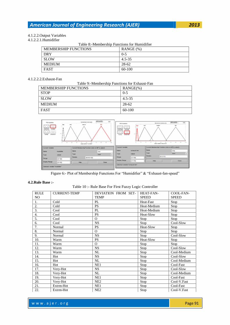
Figure 6:- Plot of Membership Functions For “Humidifier” & “Exhaust-fan-speed”
4.2.Rule Base :-
Table 10 :- Rule Base For First Fuzzy Logic Controller
RULE
NO
CURRENT-TEMP DEVIATION FROM SET-
TEMP
HEAT-FAN-
SPEED
COOL-FAN-
SPEED
1. Cold PL Heat-Fast Stop
2. Cold PS Heat-Medium Stop
3. Cool PL Heat-Medium Stop
4. Cool PS Heat-Slow Stop
5. Cool O Stop Stop
6. Cool NS Stop Cool-Slow
7. Normal PS Heat-Slow Stop
8. Normal O Stop Stop
9. Normal NS Stop Cool-Slow
10. Warm PS Heat-Slow Stop
11. Warm O Stop Stop
12. Warm NS Stop Cool-Slow
13. Warm NL Stop Cool-Medium
14. Hot NS Stop Cool-Slow
15. Hot NL Stop Cool-Medium
16. Hot NE1 Stop Cool-Fast
17. Very-Hot NS Stop Cool-Slow
18. Very-Hot NL Stop Cool-Medium
19. Very-Hot NE1 Stop Cool-Fast
20. Very-Hot NE2 Stop Cool-V.Fast
21. Extrm-Hot NE1 Stop Cool-Fast
22. Extrm-Hot NE2 Stop Cool-V.Fast
American Journal of Engineering Research (AJER) 2013
w w w . a j e r . o r g
Page 92
Table 11 :- Rule Base For Second Fuzzy Logic Controller RULE NO.
CURRENT TEMPERATURE
HUMIDITY HUMIDIFIER SPEED
EXHAUST FAN SPEED
1 Temp-Range-A DRY Fast Stop
2 Temp-Range-A NTD Medium Stop
3 Temp-Range-A S-1 Stop Stop
4 Temp-Range-A S-2 Stop Slow
5 Temp-Range-A NTW Stop Medium
6 Temp-Range-A WET Stop Fast
7 Temp-Range-B DRY Fast Stop
8 Temp-Range-B NTD Medium Stop
9 Temp-Range-B S-1 Slow Stop
10 Temp-Range-B S-2 Stop Stop
11 Temp-Range-B NTW Stop Medium
12 Temp-Range-B WET Stop Fast
Figure 7:-Matlab Rule Editor for temperature & humidity controller
4.3.Fuzzification:-
We select two random values of input variables from first fuzzy logic controller to demonstrate how
fuzzification is done in both the fuzzy logic controller used in this system.
In the first fuzzy logic controller, the signal value of current-Temperature=13C intersects with fuzzy variables
"Cold" and "cool", where "cold" is taken as the first fuzzy variable f[0] and "Cool" is the second fuzzy variable,
f[1]. The f[0] maps to the membership function value of 0.86 while f[l] maps to the value of 0.13. Similarly, for
the input value of “deviation-from current-temperature”=+10,the corresponding intersection of fuzzy variables
are "PS" as the second active fuzzy variable f[2] and "PL" as the first active fuzzy variable f[3]. The f[2] will
thereby map to the membership function value of 0.04 while f[3] corresponds to 0.96.
Table 12 :- Results Of Fuzzification:- INPUT VARIABLES VALUES REGION SELECTION FUZZY SET CALCULATION
CURRENT TEMPERATURE
13 0<13<15 f1=(15-13)/15=0.13 f0=1-0.13=0.86
DEVIATION-FROM-SET-TEMPERATURE
+10 0<10<10.5 f3=(10.5-10)/10.5=0.04 f2=0.96
Figure 8:- Block Diagram Of Fuzzification Model
American Journal of Engineering Research (AJER) 2013
The inference block accepts four inputs from the Fuzzification process and the inputs of the inference
would be f[O], f[l], f[2] and f[3]. The min-max inference method uses the min operator between the two inputs
(rule's antecedent) resulting from rule conditions and the rules are finally combined by using OR operator and
interpreted as the max operation for each possible value of the output variable. Hence four outputs RO, RI, R2,
and R3 will be generated. The values of f[O], f[l], f[2] and f[3] are 0.86, 0.13, 0.96 and 0.04 respectively.
Applying the max-min composition, f[O] and f[l] will perform the operation with f[2] and f[3] to output the R
values as follows:
RO=f(0) ^ f(2) = f(0) AND f(2) =0.86 AND 0.96 = 0.86
R1= f(0) ^ f(3) = f(0) AND f(3) = 0.86 AND 0.04 =0.04
R2= f(1) ^ f(2) = f(1) AND f(2) = 0.13 AND 0.96 = 0.13 R3= f(1) ^ f(3) = f(1) AND f(3) = 0.13 AND 0.04 = 0.04
Note that the sign ^ indicates that a minimum value will be taken between the two membership
function values. Also, in Mamdani-min, minimum is also interpreted as ANDing the two membership function
values. However, it is important to note that this is not a logical ANDing. Rather, it is the comparison to obtain
the minimum between the two membership functions. The inference model example of its input and outputs are
shown in Fig . 10.
Figure 10:-Block Diagram Of Inference Engine
4.5.Rule Selector:-
The rule selector receives two crisp values of temperature and humidity. It gives singleton values of
output functions under algorithm rules applied on design model. For two variables, four rules are needed to find
the corresponding singleton values S1, S2, S3 and S4 for each variable according to these rules are listed in
TABLE 13. The rule base accepts two crisp input values, distributes the universe of discourse into regions with
each region containing two fuzzy variables, fires the rules, and gives the output singleton values corresponding
to each output variable. Fig. 11 shows the main block diagram of the Rule Base.
Table 13:-Illustration Of Rules For The Applied Model
Figure 11:- Block Diagram Of Rule Base
American Journal of Engineering Research (AJER) 2013
w w w . a j e r . o r g
Page 94
This process is achieved by dividing the universe of discourse into six regions; with each region containing only
two fuzzy variables. The illustrations of the region divisions are shown in Fig 12.
Figure 12:-Illustration of Region Deivisions
Table 14:- Division Of Regions For Current Temperature And Deviation From Set-Temperature
INPUTS REGIONS RANGE OF VALUES
CURRENT-TEMPERATURE
1. 8-16
2 16-20
3 20-24
4 24-29
5 29-35
6 35-44
DEVIATION FROM
SET-TEMPERATURE
1 -26 to -15.75
2 -15.75 to -9.5
3 -9.5 to -3.5
4 -3.5 to 0
5 0 to 5.25
6 5.25 to 18
4.6.Deffuzifier:-
In this system, four defuzzifiers control the actuators; heat-fan-speed, cool-fan-speed, humidifier and
exhaust-fan-speed. The defuzzification process provides the crisp value outputs after estimating its inputs [1].
But as we are citing an example of how the defuzzification is done, we select only 2 defuzzifiers that control the heat-fan and cool-fan-speeds in correspondence to the current-temperature=+13 & deviation=+10. So 8 inputs
are given to each of two defuzzifiers, four values of R0, R1, R2, R3 from the outputs of inference engine and
four values S0, S1, S2, S3 from the rule selector .
Each defuzzifier estimates the crisp value output according to the center of average (C.O.A) method using the
mathematical expression ∑ S[i]*R[i] /∑R[i] , where i = 1 to 4. Each. output variable membership function plot
consists of five functions with the same range values for simplification
Figure 13:- Block Diagram Of Defuzzifier
V. RESULTS AND DISCUSSION According to the results of inference engine∑R[i]=R0+R1+R2+R3= 0.86+0.04+0.13+0.04=1.07
Table 15:- Designed Value For Heat-Fan-Speed
Si Ri Si*Ri
0.8 0.86 0.688
0.5 0.04 0.02
0.5 0.13 0.06
0.22 0.04 0.008
American Journal of Engineering Research (AJER) 2013
Using the above mathematical expression the crisp values for output variables were determined and the
results were found according to the MATLAB simulation as shown in Fig.14. These results are compared in
TABLE 17 and found correct according to the design model. MATLAB simulation was adapted according to the arrangement of membership functions for four rules as given in TABLE 13.
In Fig. 14 the same values of input variables, Current-Temperature=13, and Deviation from set-
temperature=+10 are shown. Various values of input and output variables match the dependency scheme of the
system design. When the temperature reaches the set value (13+10=23’C),the humidifying controller gives the
correct output as designed .
Figure 14:-Matlab Rule Viewer
The correctness of results shows the validity of the simplified design work for processing system using fuzzy
control system.
5.1.COMPARISON BETWEEN CALCULATED & SIMULATED RESULT:-
Table :-17
RESULT HEAT-FAN-SPEED COOL-FAN-SPEED
Design values 72.6 2.5
Calculated values 72.5 2.5
% error 0.13 0
VI. SIMULATED GRAPH DISCUSSION:- This system was simulated for the given range of input variables. In this design model, the speed of heat-fan and
cool-fan depends upon the selected value of temperature sensor, whereas humidifier and exhaust fan speeds
depend on the value of both humidity and temperature sensors . The simulated and calculated results are
according to the reliance scheme.
American Journal of Engineering Research (AJER) 2013
w w w . a j e r . o r g
Page 96
Figure 15 :- 3d Plots Between (a)Current Temperature & Deviation With Heat Fan Speed ; (b) Current
Temperature & Deviation With Cool-Fan-Speed ; (c) Current Temperature & Current Humidity With
Humidifier ; (d) Current Temperature & Current Humidity With Exhaust-Fan-Speed
VII. SOME SPECIAL CHARACTERISCTICS OF OUR PROPOSED MODEL (a).The proposed room temperature and humidity controller works perfectly over a wider range of temperature
8-44 0 C.
(b).There are two controllers in this system which measures temperature and humidity respectively. Both are
designed using fuzzy logic. After the user sets a desired room temperature, the temperature controller starts immediately to bring back the room temperature to desired value in much shorter time. And when the current
temperature is close to to desired value, the humidity controller starts working the get the ideal relative humidity
for that temperature.
(c).The number of membership functions of input and output variables of both temperature and humidity
controllers are more while difference between upper and lower limits of each range is reduced. This improves
the accuracy and sensitivity of the controllers.
(d).The output of each of the controllers is calculation adaptive and is sensitive to small variation of
temperatures.
(e).The efficiency of this model is very high as %error between calculated and measured value for a given
temperature is approximately close to 0.15 only (shown in the paper).
VIII. CONCLUSION The algorithmic design approach makes the system efficient and absolutely under control. The analysis clearly
maps out advantage of fuzzy logic in dealing with problems that are difficult to study analytically yet are easy to
solve intuitively in terms of linguistic variables. In case of the Air-Conditioning system, fuzzy logic helped
solve a complex problem without getting involved in intricate relationships between physical variables. Intuitive
knowledge about input and output parameters was enough to design an optimally performing system. The utility
of the proposed system in processing plants is being carried out and in future it will help to design the advanced
control system for the various industrial applications in environment monitoring and management systems.
IX. FUTURE WORK I. Designing a powerful ground source reversible pumps using fuzzy logic controller which can handle a
wider range of temperature and can heat and cool more sensitively and simultaneously.
II. Adding more intelligence to the room condition controller like occupancy, auto human detector and
adjusting itself according to outdoor temperature and humidity at various times a day and all round the
year.
III. In future we will come up with a device that implements the Fuzzy Logic controller in an embedded
system which can be used for increasing the efficiency of Room Air Conditioners.
American Journal of Engineering Research (AJER) 2013
w w w . a j e r . o r g
Page 97
REFERENCES [1]. I.J. Nagarath,M. Gopal, Control systems engineering (New Delhi,New age international (P) limited,2007)
[2]. Technical case studies on fuzzy logic control system from http://www.wikipedia.org,
[3]. David P. Shelton,Air properties: temperature and relative humidity, University of Nebraska-Lincoln
Extension, Institute of Agriculture and Natural Resources, 2008 [4]. Shabiul Islam, Shakowat, ”Development of a Fuzzy Logic Controller Algorithm for Air-conditioning
System”, ICSE2006Proc2006 IEEE
[5]. M. Saleem Khan and Khaled Benkrid, “A proposed Grinding and Mixing System using Fuzzy Time
Control Discrete Event Model for Industrial Application”, Lecture Notes in Engineering and Computer
Science vol. 2175 2009, p.p. 1231-1236, Directory of Open Access Journals (DOAJ)
[6]. Shakowat Zaman Sarkar, “A proposed Air–conditioning systemusing Fuzzy Algorithm for Industria
Application” ICSE IEEE Proc. (2006) 832-834
[4] M. Spott and D. Nauck, “Towards the automation of intelligent data analysis” Appl. Soft Comput.
6(2006) 348-356.
[7]. Zain, Z.M. ; Kuantan ; Abdullah, N.H. ; Hanafi, A.H.M. - Microcontroller-Based Energy Saving Control
for Air - Conditioning System Using Fuzzy Logic Approaching: An Overview- Research and Development, 2006. SCOReD 2006. 4th Student Conference on date 27-28 June 2006
[6]. Islam, M.S. ; Multimedia Univ., Cyberjaya ; Zaman Sarker, M.S. ; Ahmed Rafi, K.A. ; Othman, .-
Development of a Fuzzy Logic Controller Algorithm for Air-conditioning System-published in
Semiconductor Electronics, 2006. ICSE '06. IEEE International Conference on date Oct. 29 2006-Dec. 1
2006
[7]. Wafa Batayneh1, Omar Al-Araidah2, Khaled Bataineh1- Fuzzy logic approach to provide safe and
comfortable indoor environment- International Journal of Engineering, Science and Technology Vol. 2,
No. 7, 2010, pp. 65-72
[9]. sanjit kumar dash, gouravmoy mohanti, abhishek mohanti”- “Intelligent air conditioning system using
fuzzy logic”, International Journal of Scientific & Engineering Research Volume 3, Issue 12, December-
2012 1 ISSN 2229-5518 [10]. M. Abbas, M. Saleem Khan, Fareeha Zafar- Autonomous Room Air Cooler Using Fuzzy Logic Control
System, International Journal of Scientific & Engineering Research Volume 2, Issue 5, May-2011 ISSN
2229-5518.
Tarun Kumar Das1
assistant professor in Electronics & Communication Engineering Department at Future
Institute of Engineering & Management under West Bengal University of Technology. His
research interest includes control system,signals and systems,Digital signal processing,
microelectronics & VLSI.
Yudhajit das2, presently 3rd year b.tech student, future institute of engg & management (Wbut),