Design of a Slowed-Rotor Compound Helicopter for Future Joint Service Missions Christopher Silva Hyeonsoo Yeo Aeroflightdynamics Directorate (AMRDEC) U.S. Army Research, Development, and Engineering Command NASA Ames Research Center, Moffett Field, California Wayne Johnson National Aeronautics and Space Administration NASA Ames Research Center, Moffett Field, California Abstract A slowed-rotor compound helicopter has been synthesized using the NASA Design and Analysis of Rotorcraft (NDARC) conceptual design software. An overview of the design process and the capabilities ofNDARC are presented. The benefits of trading rotor speed, wing-rotor lift share, and trim strategies are presented for an example set of sizing conditions and missions. NOMENCLATURE Acronyms DGW Design Gross Weight GW Gross Weight HOGE Hover out of Ground Effect IRP Intermediate rated power ISA International Standard Atmosphere MCP Maximum continuous power MRP Maximum rated power MTOW Maximum Takeoff Weight NDARC NASA Design and Analysis of Rotorcraft SFC Specific fuel consumption SRC Slowed-Rotor Compound Symbols 6 Rotor solidity (geometric) CD Drag coefficient CL Lift Coefficient CT Rotor thrust coefficient Cu, Weight coefficient k 1,000 feet of elevation INTRODUCTION A compound helicopter is a helicopter that incorporates an auxiliary propulsor for forward thrust and/or a wing for auxiliary lift. By compounding the rotor, the rotor may be offloaded at higher speeds, with advantages in reduced power and potentially reduced loading on the rotor dynamic components. A compound helicopter typically Presented at the American Helicopter Society Aeromechanics Specialist's Conference, San Francisco, CA, January 20-22, 2010. This is a work of the U.S. Government and is not subject to copyright protection. achieves higher speed, better cruise efficiency, and can operate at higher altitudes. The wing can also provide a convenient mounting location for external stores and improve the maneuver performance in forward flight. Typically, compound helicopters pay penalties in hover performance due to increased download and power losses associated with the auxiliary propulsor, plus the extra weight of the propulsor and main wing. Operationally, the wing can be an issue for storage and transport, and can impede the egress of passengers in some circumstances. For attack helicopter missions, compound helicopters such as the AH-56A Cheyenne (propulsor and wing) and S-67 Blackhawk (wing) have been developed in response to the perceived need for greater speed and range. For utility and troop transport missions, compounds such as the X-49A Speedhawk (propulsor and wing) have been developed. Other recent studies, such as Sikorsky's X2 demo (propulsor) have also centered on the compound helicopter configuration as potentially desirable. For traditional helicopters, as true airspeed increases, advancing tip mach numbers become large and retreating blade stall occurs, leading to performance degradation and increased vibration. Slowing the rotor speed can alleviate this, albeit at the cost of reduced lifting capability and retreating blade stall. By unloading the rotor with a wing, the loss of rotor lifting capability is mitigated. A study was undertaken to explore the factors affecting design of a slowed-rotor compound helicopter using a new rotorcraft design code, NASA Design and Analysis of Rotorcraft (NDARC, Ref. 1). A single main-rotor layout, with an anti-torque rotor, a pusher propeller and a wing, was synthesized and sized against a design mission and four design conditions. https://ntrs.nasa.gov/search.jsp?R=20100024364 2018-07-09T23:13:15+00:00Z
Transcript
Design of a Slowed-Rotor Compound Helicopter for Future Joint ServiceMissions
Christopher Silva Hyeonsoo YeoAeroflightdynamics Directorate (AMRDEC)
U.S. Army Research, Development, and Engineering CommandNASA Ames Research Center, Moffett Field, California
Wayne JohnsonNational Aeronautics and Space Administration
NASA Ames Research Center, Moffett Field, California
AbstractA slowed-rotor compound helicopter has been synthesized using the NASA Design and Analysis ofRotorcraft (NDARC) conceptual design software. An overview of the design process and the capabilitiesofNDARC are presented. The benefits of trading rotor speed, wing-rotor lift share, and trim strategies arepresented for an example set of sizing conditions and missions.
NOMENCLATUREAcronymsDGW Design Gross WeightGW Gross WeightHOGE Hover out of Ground EffectIRP Intermediate rated powerISA International Standard
AtmosphereMCP Maximum continuous powerMRP Maximum rated powerMTOW Maximum Takeoff WeightNDARC NASA Design and Analysis of
RotorcraftSFC Specific fuel consumptionSRC Slowed-Rotor Compound
INTRODUCTIONA compound helicopter is a helicopter that incorporates anauxiliary propulsor for forward thrust and/or a wing forauxiliary lift. By compounding the rotor, the rotor may beoffloaded at higher speeds, with advantages in reducedpower and potentially reduced loading on the rotordynamic components. A compound helicopter typically
Presented at the American Helicopter SocietyAeromechanics Specialist's Conference, San Francisco,CA, January 20-22, 2010. This is a work of the U.S.Government and is not subject to copyright protection.
achieves higher speed, better cruise efficiency, and canoperate at higher altitudes. The wing can also provide aconvenient mounting location for external stores andimprove the maneuver performance in forward flight.Typically, compound helicopters pay penalties in hoverperformance due to increased download and power lossesassociated with the auxiliary propulsor, plus the extraweight of the propulsor and main wing. Operationally, thewing can be an issue for storage and transport, and canimpede the egress of passengers in some circumstances.
For attack helicopter missions, compound helicopters suchas the AH-56A Cheyenne (propulsor and wing) and S-67Blackhawk (wing) have been developed in response to theperceived need for greater speed and range. For utility andtroop transport missions, compounds such as the X-49ASpeedhawk (propulsor and wing) have been developed.Other recent studies, such as Sikorsky's X2 demo(propulsor) have also centered on the compound helicopterconfiguration as potentially desirable.
For traditional helicopters, as true airspeed increases,advancing tip mach numbers become large and retreatingblade stall occurs, leading to performance degradation andincreased vibration. Slowing the rotor speed can alleviatethis, albeit at the cost of reduced lifting capability andretreating blade stall. By unloading the rotor with a wing,the loss of rotor lifting capability is mitigated.A study was undertaken to explore the factors affectingdesign of a slowed-rotor compound helicopter using a newrotorcraft design code, NASA Design and Analysis ofRotorcraft (NDARC, Ref. 1). A single main-rotor layout,with an anti-torque rotor, a pusher propeller and a wing,was synthesized and sized against a design mission andfour design conditions.
Following the initial sizing of the aircraft with thesimplified aerodynamic models of NDARC, main rotoranalysis was performed with CAMRAD II, acomprehensive rotorcraft analysis tool. Thecomprehensive analysis results were used to find acompromise between hover and high speed flightperformance and provide better estimates for rotorperfornance than the initial NDARC inputs. NDARCsizing was then repeated with the new parameters.
Off-design performance analyses were performed usingNDARC to generate some fallout aircraft capability curvesand to explore aircraft trim and performancecharacteristics. Using fallout hover ceiling capabilitycalculated by NDARC and a separate climate modelingtool, hover performance was examined. A simplecomparison was performed to examine how the slowed-rotor compound configuration fares when compared tohistorical transportation efficiency for helicopters andfixed wing aircraft.
APPROACH
NDARC
NDARC is a conceptual/preliminary design and analysiscode for rapidly sizing and conducting performanceanalysis of new rotorcraft concepts, with frameworks forintroducing multiple levels of fidelity. NDARC is writtenin Fortran 90/95 and has a modular code base, facilitatingits extension to new concepts and the implementation ofnew computational procedures. NDARC version 1.1 wasused in this design activity.
NDARC has extensive documentation, both in a theorymanual and in an input manual. There is an NDARCSerious Users Group (SUG), members of which test andperiodically suggest modifications and improvements tothe code. The SUG maintains a web-based Wiki; hostedby NASA, with reference documentation, tutorials, bugfixes, release notes, and some ancillary utility programs.The Wiki also serves as a location for hosting documentspertaining to the development of ancillary tools forNDARC.
A typical NDARC nun consists of a sizing task, followedby off-design performance analysis. During the sizingprocess, point condition and mission performance arecalculated and the aircraft is resized both geometricallyand mechanically until the convergence criteria are met.NDARC runs, including sizing and perfornance analysis,typically are completed on the order of minutes on adesktop computer. Once a sizing task has been performed,fiirther analysis of the configuration can be performed bytaking the sized aircraft as input to NDARC in eitheranother case (or cases) within the same job, or as input toa case in a new job.
NDARC provides default configurations and trimstrategies for several coimnon rotary wing configurations,
including single main-rotor helicopters, tandemhelicopters, coaxial helicopters, and tilt-rotors. In each ofthese default examples, trim strategies have been defined;providing a set of starting points for a design study. In thecase of the compound, especially when rotor speed is alsovaried, there are many indeterminate trim strategies thatcan be developed; and it is up to the designer to developtrim strategies that will best use the various controleffectors to achieve trimmed flight. NDARC performstrim analysis in each flight condition or mission segment.A variety of control effectors can be used to achieve trim.NDARC allows different control states (connections ofpilot controls to component controls) to be defined andadjusted during trimining; further, a wide variety ofparameters, such as gear ratios, rotor speeds, rotordiameter, etc., can be varied based upon pre-definedschedules. For indeterminate systems, such as a compoundwith redundant effectors, a strategy external to NDARC isneeded to select a schedule for the redundant effectors. Inthis study, the schedules were selected to achieveminimum weight while retaining control margins.
NDARC is programmed with a large amount of run-timeflexibility, including options to allow the designer to selectsolution procedures and specify starting y point trimestimates. An example is the freedom to select secant.Golden Section, or some other user-coded solutionprocedure for finding maximum effort speeds, such as bestrange speed. For each flight condition or mission segment,the initial trim estimates may be input, or the case solutionmay be set to have all initial trim estimates use the lastknown trim state as the starting estimate. NDARC alsoprovides the facility to output various solution parametersto a file during the run, allowing the user to traceconvergence in sizing and trim. These diagnosticcapabilities have proven to be valuable in exposing theunderlying sources of convergence problems.
CAMRAD II
NDARC implements simplified aerodynamic models forrotors and lifting surfaces. CAMRAD II is a tool foraeromechanical analysis of rotorcraft that incorporates acombination of advanced analvtical and numericalmethods, including multibody dynamics, nonlinear finiteelements, and rotorcraft aerodynamics. The CAMRAD IIaerodynamic model for the rotor blade is based on lifting-line theory using steady two-dimensional airfoilcharacteristics and a vortex wake model and capable ofcomputational fluid dynamics""computational structuraldynamics coupling. CAMRAD II wake analysiscalculates the rotor nonuniform induced velocities usingrigid, prescribed, or free wake geometry.
CAMRAD II was used to provide more accurate estimatesof main-rotor performance, and to explore the designvariables in the rotor geometry. The CAMRAD IIestimates were then entered into NDARC for anotherround of sizing.
Design ProcessIn order to achieve an optimal and balanced design, aconsiderable amount of the designer's judgment must beused in the iterations. The flowchart in Figure 1 illustratesan overview of the design process. The dotted lineencompasses the portions of the process that areperformed during an NDARC execution. The thick solidbox encompasses the changes that were made to thedesign between nuns, in order to improve the overallaircraft, based upon the design objectives and constraintsthat NDARC does not consider. The list shown in theflowchart is not exclusive; other parameters were alsomodified, such as number of blades on each rotor to keepblade aspect ratios from becoming too low.
CreateCondition,
Mission Files
Create AircraftConfigurationDefinition Files Main RotorVtip
Trim SwitchoverLift Share
Modify Tail Rotor CantCondition, Rotor Mast AngleMissions Wing ARto match Pusher SolidityAircraft
Yes
Create/ Output NoModify Job OK?Definition Files
Run Sizing ExamineConditions, Size and
Missions Performance
Run Off-Design Examine JobConditions, Convergence
Missions Results
Figure 1. Flow of the NDARC sizing activity
Design GoalsThe design goals for this study are to explore a specificaircraft configuration, a slowed-rotor compoundhelicopter, for a representative set of requirements, so thelimitations and possibilities available with theconfiguration can be delineated. Because no single set ofspecific operational scenarios have been defined, a rathergeneric mission has been selected such that the final sizedaircraft can perform many different missions and tasks,but is not optimized for any one type of mission. The sizedaircraft, however, does perform many tasks and the modelcan be quickly converted to size an aircraft that isoptimized for a specific mission or mission sets. Many ofthe processes and trades have been explored anddocumented for future studies.
The sizing process consisted of first establishing baselinerequirements and objectives that could be used to drive aNDARC sizing exercise. The requirements were manifestin a set of performance conditions and a mission, alongwith targets for disk loadings and control strategies. Oncethe requirements and objectives were in place, an aircraftwas synthesized that would have the features necessary toperforni the sizing against. Finally, the aircraft was sizedfor the design conditions and missions and analyzed foroff design performance.
AIRCRAFT SYNTHESISSynthesis of the aircraft in this context means defining theconfiguration of the aircraft and setting sizing constraintsand free variables. Synthesis establishes the number andrelative placement of rotors, lifting surfaces, and bodies.The general topology of the drive system and the engineand airframe technology are also established. Operationaltrim strategies and schedules are also defined.
General Configuration SynthesisThe aircraft in this study is a single main-rotor helicopterwith a tail (anti-torque) rotor placed at the rear. There is asmall separation between the tail-rotor and the main-rotor.For the slowed-rotor compound, an existing helicopterdefinition was modified to have both a wing and anauxiliary propeller, with appropriate controls defined. Awing is located below and behind the main rotor, and apusher propeller is located behind the tail rotor. A largefuselage has been accounted for, in order to provide for asubstantial cargo or passenger capacity. The fuselage hasbeen sized to seat approximately 9 passengers. For thedesign mission, an external payload of 5.0001b with 20square feet of parasite drag area has been assumed torepresent the carriage of external stores.
Figure 2. Sketch of the compound helicopter
Component SynthesisFuselageThe fuselage was sized to acconnnodate two crew and 9passengers.
100
a`
gl oa`v
a
v
w10 100Rotor Diameter, ft
-- I ^ l l l l -^--i ii II I II I II II II
IIII II II
IIIIII
III
Hub Drag--- -, ; ;f
_-- ----- +-----------^--------_-- ----- . Current
:----- 1 I
II
I II I
II
II
I
1I ..I1 •1
IIIIIII
I II II II II II I
IIIIII
II1---III
Figure 4. Hub drag versus diameter
performance. A taper of 0.8 was assumed for the mainrotor blades, with a root cutout area that extended to 15%radius by designer's choice in absence of a specific design.
NDARC allows the use of rotor tip speed schedules thatvary with airspeed, and also direct-input tip speeds foreach condition or segment. The near ratio for each rotor isset by specifying a reference tip speed and using theengine definition rpm. In the case of the slowed-rotorcompound in this study, there was only one gear specified,so as the main rotor was slowed to a fraction of itsreference tip speed, the engines, tail rotor, and pusher wereall slowed by the same fraction of their reference speeds.
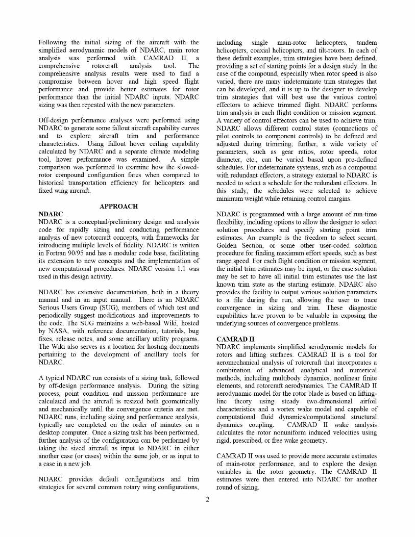
RotorsThe main-rotor dimensions were sized based upon diskloading, tip speed, and Cw/6. Disk loading for the mainrotor was set based upon experience with similarhelicopters, and was also varied slightly between runs toadjust gross weight and rotor diameter. Final maximumdisk loading was set to be 9_31b/ft 2 . Operationalrequirements for the helicopter will likely dictate themaximum disk loadings and diameters for various designconditions.
The forward tilt of the mast was varied in the design study,by adjusting the mast angle between nuns. A separatecontrol for mast tilt has been implemented in the NDARCaircraft definition, but was not used as a trim control inany point condition or mission segment. Particularattention was paid to the effects on gross weight andmaximum speed when determining the mast angle for themain rotor. No lateral tilt has been used.
Main rotor pylon drag was estimated using a typical C D of0.04 based on wetted area, with the pylon wetted areascaling with the weight of the drive system to the 2/3power, which is a standard scaling option in NDARC.
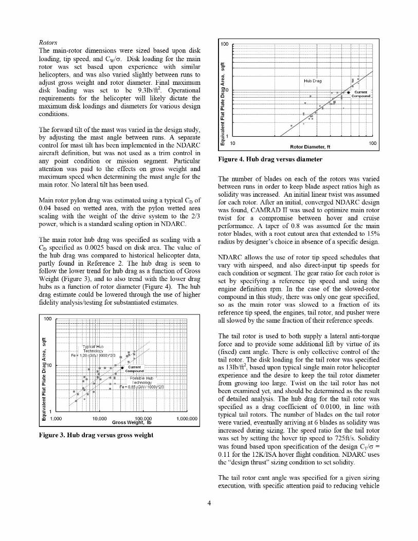
The main rotor hub drag was specified as scaling with aCD specified as 0.0025 based on disk area. The value ofthe hub drag was compared to historical helicopter data,partly found in Reference 2. The hub drag is seen tofollow the lower trend for hub drag as a function of GrossWeight (Figure 3), and to also trend with the lower draghubs as a function of rotor diameter (Figure 4). The hubdrag estimate could be lowered through the use of higherfidelity analysis/testing for substantiated estimates.
100 —
--k t ; Yy t
S
a
'10vMn
am
1
w1,000 10.000 100.000 1.000.000Gross Weight, Ib
I lili Ili 1 ili
I I l l i l l! I 1 1 1 1 iI i
l i
I ! 1 1 1 111 t I 1 111 I! 11! 1 1 1 1 1 1 t
I ! 1 1 1 1 1 1 !-
I 1 1 1 1I 1 1 1 1 11 1 11 1______y.____.._._._._.__II I
TyplCa^ Y1 I)I I I I I ^ II I I I I ,Y I
-ItI 11 t I t I1 l l
------'---^I Technology I I I I -----'---I *--+-I I t*- l lII Fe `- 1,20 (GW 1: 000)"213 I ^. II* ,^' r l I II I I II I l i lil
was found based upon specification of the design C T/6 =0.11 for the 12K/ISA hover flight condition. NDARC usesthe "design thrust" sizing condition to set solidity.
The number of blades on each of the rotors was variedbetween runs in order to keep blade aspect ratios high as
solidity was increased. An initial linear twist was assumedfor each rotor. After an initial ; converged NDARC designwas found, CAMRAD II was used to optimize main rotortwist for a compromise between hover and cruise
The tail rotor is used to both supply a lateral anti-torqueforce and to provide some additional lift by virtue of its(fixed) cant angle. There is only collective control of thetail rotor. The disk loading for the tail rotor was specifiedas 131b.ft/'', based upon typical single main rotor helicopterexperience and the desire to keep the tail rotor diameterfrom growing too large. Twist on the tail rotor has notbeen examined yet, and should be determined as the resultof detailed analysis. The hub dray for the tail rotor wasspecified as a drag coefficient of 0.0100, in line withtypical tail rotors. The number of blades on the tail rotorwere varied, eventually arriving at 6 blades as solidity wasincreased during sizing. The speed ratio for the tail rotorwas set by settin g the hover tip speed to 725ft/'s. Solidity
The tail rotor cant angle was specified for a given sizingexecution, with specific attention paid to reducing vehicle
weight and keeping the tail rotor diameter from growingtoo large.
The pusher rotor radius, tip speed and solidity weredirectly specified. Specifying the values in this way allowsthe designer to selectively vary the CT/6 for the high speedcondition independently.
Pusher rotor hub drag coefficient has been assumed to be0.0100, the same as the tail rotor. The speed ratio of thepusher relative to the main rotor was fixed manually foreach run, in order to keep the tip speed below a helicalMach number of 0.90 to keep the tip airfoils below thedrag divergence Mach number at the 200ktxs high speeddesign point, but still high enough that the pusher CT/6was below blade stall. This process can be made morerigorous by specifying a CT/6 value as a sizin g criterion.
A relatively high solidity of 0.2 was selected for thepusher rotor in order to keep tip speeds and rotor diameterlower. The number of blades was set to 6 blades to keepthe blade aspect ratio higher. A highly twisted bladeshould be used for the pusher. Twist on the pusher rotorhas not been defined, and should be determined as theresult of detailed analysis. Potentially declutching thepusher in hover and compound mode would allow greatertwist to be used without a penalty from profile drag inthose fli ght control modes.
Wing-Rotor Lift ShareFor wing and rotor lift share, a fixed incidence was used inthe compound trim state, and a target lift coefficient usedfor high-speed compound trim state. This allows thedesigner to see which lift coefficient results in the bestaircraft (perhaps lowest DGW), and see what range ofincidences are required to achieve that. Then the designercan choose to make the trade between variable incidenceand variable flaperon as methods to achieve the desiredtrim state. A fixed value of the wing lift could also be atarget, but lift coefficient was chosen because it is likely tobe fixed or nearly fixed for varying speed once the rotorwake is not impinging on it, and the lift coefficient impliesa maneuver margin that is available to the l ying relative tolevel un-accelerated flight trim.
The wing aspect ratio was fixed for each nun, and adjustedto yield the lowest design gross weight. In a more detailedanalysis, the effect of wing lift on rotor loads can be usedto potentially reduce rotor component weights. NDARCdoes not have that level of fidelity, and this trade was notexamined in the current design study.
Wing loading is defined by assumin g a fraction of grossweight and then calculating the required planform area ofthe wing. For a compound, where the trim settingsdetermine the lift carried by the rotor, the wing lift fractionmust be iteratively converged to make the design wingloading meaningful. In absence of this iterative process,
the actual wing loadin g must be calculated manually,based on the trim condition. The lift fraction for thecompound was adjusted by setting a target lift coefficientfor the main wing in high-speed compound trim mode.The wing incidence is scheduled to be driven by a targetlift coefficient in high speed cruise mode, and is fixedotherwise.
The wing has full span flaperons. The flaperons have notbeen used in this study, and have always been leftundeflected in all analysis. It may be beneficial, dependingon the mission set and structural design, to use flaperonsrather than variable win g incidence for trim, and theflaperons acting as ailerons can also be used to maintainlevel roll attitude, whereas the current trim strategy usesroll attitude to balance out the rotor hub moment, tail rotoroffset torque, and pusher torque about the longitudinalaxis.
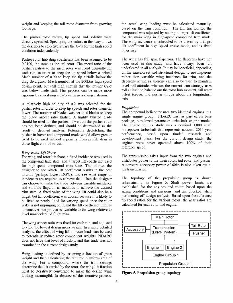
PropulsionThe compound helicopter uses two identical engines in asingle engine group. NDARC has, as part of its basepackage, a referred parameter turboshaft engine model.The engine in this study was a nominal 3,000 shafthorsepower turboshaft that represents notional 2015 yearperformance, based upon fitnded research anddevelopment plans. For the current design study, theengines were never operated above 100% of theirreference speed.
The transmission takes input from the two engines anddistributes power to the main rotor, tail rotor, and pusher.A constant accessory power of 60hp is also taken out atthe transnssion.
The topology of the propulsion group is shownschematically in Figure 5. Shaft power linvts areestablished for the engines and rotors based upon thesizing conditions and nussions, and are checked whenperforrtung off-design analysis. Based upon the referencetip speed ratios for the various rotors, the gear ratios arecalculated for each rotor and engine.
Technology factors for the aircraft weights have beenassumed. These tech factors are derived from a metal-skinned fuselage utility helicopter.
Controls and Control SchemesNDARC uses a system for setting up controls wherebycontrol variables are identified by name. These trimvariables generally correspond to pilot inputs, but can beany definition. For each trim state, the control variablesare mapped to a trim quantity. The trim quantities are freebody forces, moments, and component forces orcoefficients. For each control effector, a matrix is definedfor each control state, mapping control variable input toeffector output.
By using multiple trim states, an aircraft may vary controleffectors used for different flight configurations. In thepresent design, trim states are used to vary the effectorsused for trimming the vehicle, and varied by condition andmission segment.
By using multiple control states, the mapping of controlvariables may be varied as the aircraft configurationchanges. For example, a tilt-rotor might use control statesto change the mapping of rudder control variable inputfrom the empennage rudder to the opposing longitudinalcyclic of the prop rotors as the nacelles tilt upwards.
The standard control schemes in NDARC for a helicopterconfueuration do not address the control effectors that areavailable in this compound configuration. Additionally,there is another degree of freedom allowed by the engineRPM, which can be used to slow the main rotor and delaycompressibility effects, but which also slows the pusherpropeller, increasing its Cr/6 and bringing it closer to stall.Thus. a minimum power trim strategy may be a goal thatis sought, beyond the force- and moment- balance trim ofa typical helicopter. The referred parameter turboshaftengine model in NDARC accounts for RPM-dependentengine performance variation
A total of 12 control variables were defined, although notall of them were used. There were three trim ystatesdefined, identified as follows: Hover, Compound, andHigh-Speed Compound.
Table 1 lists the trim quantities that were used in thepresent compound helicopter. The "X" entries in the tabledenote quantities that were sol ved for each trim state.Entries marked "Specified" were solved to a target valuefor each flight condition or mission segment. Table 2 liststhe trim variables that were free to adjust (marked with"X") for each trim state.
Table 1. Trim quantities
High SpeedTrim Quantity Hover Compound CompoundForce X X XForce Y X XForce Z X X XMoment X X XMoment Y X XMoment Z X X XCr, Wing 1 SpecifiedPusher Thrust Specified
Table 2. Trim variables
High SpeedTrim Variable Hover Compound CompoundRoll X XPitch XYawMR collective X X XMR long. cyclic XMR lat. cyclic X XPedal (TR coll.) X X XHor. tail inc. XWing inc_ XPusher coll. X X
Tech Factors and Assumed Component AttributesIn developing parametric weight estimates, it is oftennecessary to assume a tech factor to account for a designdecision that has a tangible advantage or disadvantagerelative to the historical database. The tech factors used inthis study represent limited new technology insertion, andare primarily manifest in the engines.
AIRCRAFT SIZINGA set of 4 point-design conditions and a sizing missionwere selected, with the design targets for each conditionand mission specified. NDARC allows multiple designconditions to be defined. Each design condition was usedto set a specific aircraft parameter, as outlined in Table 3.
ISA 3k/ 91.5 200ktAtmosphere 12k/ ISA 3k/ 91.5F Sea 6k/ 95F
LevelISA
Weight DGW DGW <Max> DGWPower 95% 95% 95% 100%
MRP MRP MRP MCPTrim State Hover Hover Hover High-
SpeedSizing Tail Trans- WMTO Engine
Rotor mission Tail and/orRadius Rotor Trans-
Radius mission
A simple design mission was used to size the engine andfuel tank requirements, shown in Table 4 and Figure 6.Multiple design missions may be used for sizing theaircraft. The design mission is performed with a fixedexternal payload with 20fe of drag area and weighing5,000lb. The entire mission is flown in a 6k'95atmosphere, although climb segments can be defined andatmospheric conditions can be varied on a per-segmentbasis. The design mission's first segment is a taxi atmaximum continuous power for 3 minutes to burn arepresentative amount of fuel. The weight at the beginningof the first segment defines design gross weight. Thesecond segment is a hover out of ground effect for 2minutes. All hovers are performed with the Hover trimstate. The third segment is a best-range cruise for 229mn,which represents the diagonal across a 300km x 300kmarea of operation. The trim state for the best rangesegments is set as high-speed compound, based on theexpectation that this yields the higher best range speed ofthe compound trims. Best range speed in this case is 99%best range speed, on the high side ; sometimes referred toas high speed cruise. The fourth segment is loitering flightat best endurance speed for 30 minutes, representing amission loiter. The trim for best endurance may be foundto be either compound or high-speed compound trim state,depending on the aircraft's exact configuration and theexternal drag of the payload. The fifth segment is a 1nunute HOGE, representing either landing and taking offagain or observing a target. The sixth segment is a 229mnreturn cruise at best range speed. The seventh segment is a1 minute HOGE for landing. A reserve segment is placedat the end, and will consist of the longer of 30 minutes ofRiel burn or 10% of mission fuel burn. Fuel burnconservatism has been used for the current study, with avalue of _5%assumed-
MCP MRP MCP MCP MRP MCP MRP MCPGW DGWTrun power hover its- hs-corV hover hs- hovrer hs-eortrp/State comp comp co np compWing 1.0 1.0 lA 1.0CL
Reserl-e Segment
Best Enclu ran ce Best EnduranceLoiter Reserve30min 30min/ 10% Fuel
Best Range Cruise Best Range CruiseHOGE 229nm HOGE 220nm HOGS
6k// 2min Imin train
9sTaxi3min
Figure 6. Design mission stick figure
The trim state shift point was found iteratively and theappropriate trim state was applied to both the best
endurance and best ran ge segments of the missions. Theprocedure for finding optimal trim state shift speed was toplot power versus airspeed for both modes, Compoundtrim from hover to about 140KTAS, and High SpeedCompound state from about 70KTAS to 210KTAS. Wherelines cross, the aircraft should snake a shift. Note that thefuselage trim angle goes from free to fixed as the aircrafttransitions from Compound to High Speed Compoundstates, and this discontinuity must be checked. There is notpresently a way to perform sweeps in NDARC where thetrim state varies, meaning that each point on the curvewould need to be manually input when building aperformance sweep schedule. In the final designedaircraft, other trades are considered and the optimalschedule is incorporated into the flight control system. Thedesigner could alternatively choose maximum maneuvermargin or control authority or minimum vibration (as theAH-56 was flown for much of its life) instead of nummumpower as the objective for choosing trim state shiftconditions. `vibration suppression could also beimplemented with higher fidelity analysis, and thevibration suppression power levels could be fed intoNDARC. Rotor resonance crossings will also affect theoperating and transition envelope.
Disk loading is important from an operational perspectiveas it largely defines the downwash environment near thehelicopter. Lower disk loadings also aid in autorotation,but other factors such as blade inertia are also important.Higher disk loadings mean that the rotor diameter isreduced, which has operational benefits in transportationand storage of the helicopter. Some excursions in diskloading were performed, in order to observe its impact ondiameter and weight of the sized vehicle.
The tail rotor was sized to provide adequate anti-torque ata hover ceiling of 12K/ISA at DGW, which is 6,000feetabove the design altitude of 6,000feet, but in an ISAatmosphere. This corresponds to a similar sizingrequirement of IOK/ISA hover for a 4K/95-capablehelicopter.
The sizing minimum HOGE ceilin g was also set to12K/ISA at DGW by the same rationale as the tail rotorsizing.
The design mission was set to be a 6K/95 mission with anexternal payload, based upon the belief that 6K./95 will bethe design driver for future rotorcraft. 4K/9.5 performanceis then fallout from the sized aircraft.
Maximum takeoff weight was fallout for the sized aircraft,with the transmission engines, and rotors fixed by othersizing points. Maximum takeoff weight is the gross weightat 95%MRP engine capability and 100% transmissioncapability, while respecting rotor CT/6 limits.
A top speed of 200kt at 6K/95 DGW and no externalpayload was set as a target, based on a slight capabilitypush beyond current helicopter performance.
The transmission is sized to accommodate a top speed of200kt at 6K/95 DGW and hover at 3K,-91.5 DGW.Transmission sizing for these two points guaranteesperformance capability. Due to the ability to operate atlower tip speeds, the transmission limits are sometimesdifferent than the engine limits, even at the sameatmospheric conditions. Also ; different parts of thetransmission and drive system are sized by the variousconditions and segments. For instance, the power to thepusher propeller is sized by the high-speed condition, andthe drive system torque happens to be sized by the highspeed condition. As can be seen in Table 5, thetransmission torque is sized by the high speedrequirement. Condition 3 sizes the maximum takeoffweight, in this case by using the maximum torqueavailable from the transmission.
CAMRAD II Alain Rotor AnalvsisThe sizing conditions and missions were used withNDARC to establish an initial estimate of the compoundhelicopter, and the main-rotor dimensions and aircraftspeeds were input to CAMRAD II for exploration of thedesign space and optimizing twist. CAMRAD II resultscalibrated the NDARC performance model.
A hingeless rotor hub was used for the main-rotor. Bladeinertial and structural properties were scaled from theblade developed for the LCTC (Ref. 7). The currentcompound helicopter has a very stiff rotor. Thus, structuraldynamics is not a significant factor in the aerodynamicperfornance shown in this paper. A stiff hingeless rotor isconsidered a good design choice, if innovative solutionsare found to keep rotor weight reasonable. In any case, itallows this paper to focus on aerodynamic performance.The calculated blade frequencies were very close to thosepresented in Ref 8. State-of-the-art rotor airfoils (VR-12and SSCA09) were used for the main rotor blades.
The blade twist was varied to obtain balanced hover andcruise performance. Four design conditions were used toselect the optimum twist; hover at 12K/ISA and 3K/91.5deg F and 200 knot cruise at 6K/95 deg F, 145 knot bestrange at 6K/9.5 deg F. The first hover condition was 725ft/sec tip speed, C T/6 = 0.1028 and the second hovercondition was 725 ft/sec tip speed, C T/o= 0.0843. Thecruise condition was 600 ft/sec tip speed, CT/6 = 0.0381,and the best range condition was 610 ft/sec tip speed,CT"'6=0.0704. The 600ft/s tip speed is slightly above the5/rev I" lag frequency of the main rotor.
An isolated-rotor, axisymmetric solution was used forhover and an isolated-rotor, wind-tunnel trim for a givenshaft tilt angle was used for forward flight perfornancecalculations. A free-wake model was used for rotoranalyses, computed by the CAMRAD II comprehensiveanalysis code.
The twist distribution had two linear segments, inboard(O.OR to 0.5R) and outboard (0.5R to LOR). Figures 1 and2 present the results for twist variation. Hover figure ofmerit was plotted against equivalent rotor drag area (D/q(ft'`) _ (PI+PO)/(V*q)), where PI is rotor induced power,PO is rotor profile power, V is airspeed, and q is dynamicpressure. For each value of outboard twist (-15, -12, and -9deg), the inboard twist values are -6, -3, 0, 3, 6 and 9 deg.Solid symbols represent for hover at 12K/ISA and opensymbols represent hover at 3K./91.5 deg F. A largenegative twist improves hover performance, but thesmaller twist gives better forward flight performance. Theresult shows that figure of merit is larger at 3K/91.5 deg Fthan at 12K/ISA for larger negative outboard twist, but thedifference diminishes as the negative outboard twist getssmaller. Equivalent rotor drag area is larger at 145 knotsthan at 200 knots due to higher rotor thrust. The designtwist of 0 deg inboard and -12 deg outboard was selectedbased on the hover-cruise compromise. At the designcondition, hover fi gure of merit values at 12K./ISA and3K/91.5 deg F are 0.766 and 0.773, respectively, and theequivalent rotor drag areas at 200 knot cruise and 145 knotbest range conditions are 14.98ft' and 39.46fe,respectively. The CAMRAD II profile and induced powersat these conditions were used to calibrate the NDARCmain-rotor perfornance model.
0.84
0.82 -60
0.80 design 9
E 0.78 - outboard twist = -15 deg0
0.76 outboard twist = -12 deg
LL 0.74
0.72 outboard twist = -9 deg
0.70 —13 14 15 16 17 18
Rotordrag Wq), ft=
Figure 7. Effect of blade twist on rotor hover andcruise at 200 knot performance (inboard twist = -6, -3,0, 3, 6, and 9 deg)
V.64
0.82 -60
0.80
0.78 outboard twist = -15 deg
a3 0.76°—° outboard twist=-12 deg
0.74
0 , 72 outboard twist= -9 deg
0.70 T38 39 40 41 42 43
Rotor drag ( D/q), ft'
Figure S. Effect of blade twist on rotor hover and bestrange at 145 knot performance (inboard twist = -6, -3,0, 3, 6, and 9 deg)
NDARC Solution Procedures and DiagnosticsNDARC provides the user with ruri-time control overmany aspects of the solution. The designer may also selectvarious levels of verbosity for the interim solution,allowing a post mortem trace of a solution's convergenceto identify the sources of divergence. Sample convergencehistories are shown in Figures 9, 10, and 11.
A simple text parsing utility has been written, whichallows the designer to quickly gage the convergence ofdesign gross weight, maximum takeoff weight, fuel tankcapacity, weight empty, engine power, power limit at theengine shaft, power ratio, and power limit of the drivesystem.
OFF-DESIGN ANALYSIS DURING SIZINGSome of the off-design analysis, such as the high speedflight tip speed sweep, was used as feedback during thesizing process of Figure 1. Other analysis was performedin order to help place the performance of the sizedrotorcraft in context.
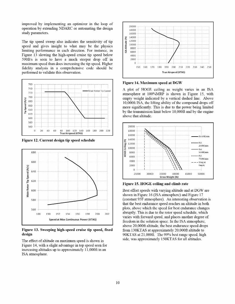
High Speed Flight Tip SpeedA simple schedule of main rotor tip speeds was selected.The schedule is shown in Figure 12, and consists of aconstant 725ft/s from hover to 90kt, then a linear ramp tothe high-speed tip speed target of 600ft/s above 150kt. Thehigh-speed target was found iteratively, by choosing avalue and monitoring the design gross weight change inthe sizing results. Once the design gross weight reached alocal minilmrm, a sweep was performed to find what tipspeed resulted in the maximum value for maximumcontinuous power speed. The tip speed was then adjustedincrementally until the peak maximum continuous powerspeed coincided with the target tip speed and nummumdesign gross weight. This sequential optimization can be
9
improved by implementing an optimizer in the loop ofoperation by extending NDARC or automating the designstudy parameters.
The tip speed sweep also indicates the sensitivity of tipspeed and gives insight to what may be the physicslimiting performance in each direction. For instance, inFigure 13 slowing the high-speed cruise tip speed below590ft/s is seen to have a much steeper drop off inmaximum speed than does increasing the tip speed. Higherfidelity analysis in a comprehensive code should beperformed to validate this observation.
760 -----T-------- ---- ----7----T----T----r----r----I I I I I I I I I
740 I I I I I I I I I
720 _ I y_ Main Rotor Tip Speed
- I--- - 1--- -- ---_---I I I I I ^
700 I-------------------ti----~----^ ---I
^ ^ I I I I I
----^---- - -----;---------}--------^----^----^-^ 680 ----I I I 1 ^ I I I I I ^I I I I I
N 660 ____L--- 1---J____J____1---- ---1____1 ---- L ---- L ---- IN I I I I I I I I I I IQ I I I I I^ 640 ____L___1___J____J____1 ---- J__ _1 ---- 1 ---- L ---- L___JC I I I I I I I I I I I._ I I I I I I I I I I I
~ 620I I I I Ir___4____ 4____--____--____ ____r____r____II I I I I I I I I I II I I I --600------r--- r ---^----^----^---^----^-I I I I I I I I I I I
Figure 13. Sweeping high-speed cruise tip speed, fixeddesign
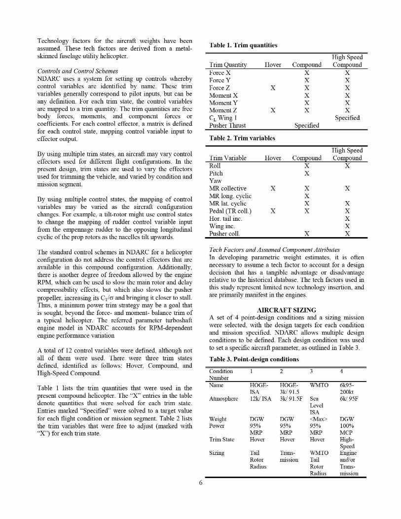
The effect of altitude on maximum speed is shown inFigure 14, with a slight advantage in top speed seen forincreasing altitudes up to approximately 11,000ft in anISA atmosphere.
A plot of HOGE ceiling as weight varies in an ISAatmosphere at 100%MRP is shown in Figure 15, withempty weight indicated by a vertical dashed line. Above10,000ft ISA, the lifting ability of the compound drops offmore significantly. This is due to the power being limitedby the transmission limit below 10,000ft and by the engineabove that altitude.
Best effort speeds with varying altitude and at DGW areshown in Figure 16 (ISA atmosphere) and Figure 17(constant 95F atmosphere). An interesting observation isthat the best endurance speed reaches an altitude in bothplots, above which the speed for best endurance changesabruptly. This is due to the rotor speed schedule ; whichvaries with forward speed, and places another degree offreedom in the solution space. In the ISA atmosphere.above 20,000ft altitude, the best endurance speed dropsfrom 130KTAS at approximately 20,000ft altitude to90KTAS at 21,000$. The 99% best range speed, highside, was approximately 150KTAS for all altitudes.
v3aa
10
30000 •------------ ---- --------
ISA DGW25000 ------------------------------------------ ------- MCP
THE SIZED AIRCRAFTNDARC provides formatted summary pages withdimensions and weights for the aircraft at the end of the
analysis. The output includes both dimensional data andestimates for weights broken out by Society of AlliedWeight Engineers (SAWE) RP-8A weight group.
Table 6. Rotor Dimensions and Propertiespresents someselected rotor dimensions for the three rotors of the currentcompound helicopter. The twists of the tail and pusherrotors have not been defined as of yet.
Table 6. Rotor Dimensions and Properties
Item Units Main Tail PusherRadius ft 33.5 9.4 8.0Solidity -- 0.1142 0.1354 0.2000(geometric)# of Blades -- 5 6 6Twist deg 0/-12 TBD TBDV, ip (hover) ft/s 725 700 953.8V, ip (cruise) ft/s 600 579 789.4Mast Tilt/Cant deg -1 15 0(+aft/up)CD Hub -- 0.0025 0.0100 0.0100Ma, (Ct,. 200ktas -- 0.81 0.79 0.74
Table 7 presents the dimensions of the flying surfaces. TheNDARC model calculates interference between thevarious components and the rotors. For the CAMRAD IIanalysis; no interaction between components wasexamined. Therefore, positioning and sizes of the flyingsurfaces may be varied as more detailed analysis isperformed.
Table 7. Flying surface dimensions
The NDARC summary weight statement showin g thehighest two levels of weight breakdown is shown in Table8y
A velocity sweep was performed at 6k/95, DGW, cleanconfiguration, with a step transition from compound trimto high-speed compound trim at 100kt. The results of this
sweep are shown in the figures below. In Figure 19, thetotal power curve is seen to be slightly lower forcompound trim below about 60kt and more substantiallylower for high-speed compound trim above 100kt. Thesplit point for this transition was selected iteratively, byplotting these sweeps and picking an approximatetransition point based upon the crossover of the powercurves. A transition between the two trim states wasselected to be 100kt. The selection of trim crossover speedcould also be chosen based on power margins, marginalcontrol authority, maneuver requirements, or operationaldetails as well.
6000 -- ---r r r 1
I
I
1 I I 1
I I I I I
5000^ ------- —Speed Sweepa I I I
I I I Iv 4000 ----- -`-------- ------- -^---- --'-3 i n Max(ontinuou,a° Povlerv 3000 --------^------ --------^ -------'-^ I I _ I
^^ i i i ----Compoundcw 2000 --------r--------r--------r--------i- (continuation)^ I I I I
I I I
i i ......• High Speed1000 ________r--------r--------r--------r (omponnd
3000----- ----=----------------- sJ-- ;--Oazsoo ------- ------------ F-----'----^-w I J. 1 - —Anti-torque
r ZDDD __________a_ ____________L______--_ Rntori0 1500 ----------I- ------- -
I ^t--------^--
I r 1 - - - - pusher Rotor0 1000------------4------ __rr--i ------ -^--
soo --- -I - --------- r ----------^1 1--
0
0.00 0.20 0.40 0.60 0.80
Horizontal Advance Ratio
Figure 20. Power split from velocity sweep
0.90 --r-- -I---T---r--T---1
I I I I I I I I I I
I I I I I I I I I I I
I I I I I I I I I I I
0.85 1 I I 1---t---r------r --- r-- r--r--r
y MR Advancing1I I I I I Z
_W
Tip Mach
I0.80 --^---r--^-- - rIrI
-rI---
TR Advancing Tlp0.75 ' Mach
~ ` 1 ^' y —
-Pusher
1 1 1 1 1 10.70 1 1 1 1 11 1 1 1 1
___ T____1 --- __r___r__r__ Advancing Tip
1 i i i i Mach
I I I I 1 I I I I I
0.65--- - ---- I I I '---'---' ---'I r r--r I
I I I I I I I I I I I
I I I I 1 I I I I I I
I I I
0.60O O O O O O O O O O O O
N ^ ^D 00 O y .^-I
W O ry.-I N
True Airspeed (KTAS)
Figure 21. Advancing tip mach
x
x
x
x
x
x
x
x
12
6--------- r------- r------- r------- r ------- r T ------- II I I I
I I I I I5--------- L_______L_____
I I I I II I I I I I I
I I ID I
I I I I I I II I I I I I I
DJI II I I I I
II I
0
0.00 0.10 0.20 0.30 0.40 0.50 0.60 0.70
Horizontal Advance Ratio
Figure 22. Equivalent lift/drag from velocity sweep
Figure 23. Main rotor CT/(y from velocity sweep
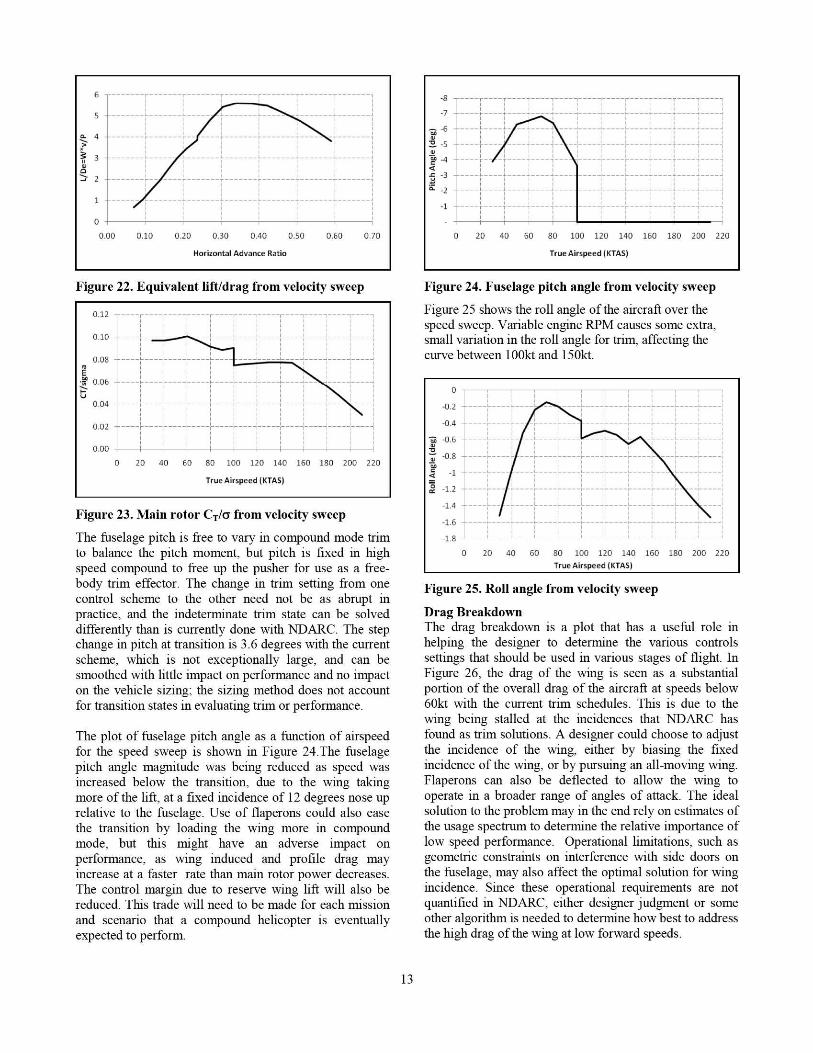
The fuselage pitch is free to vary in compound mode trimto balance the pitch moment, but pitch is fixed in highspeed compound to free up the pusher for use as a free-body trim effector. The change in trim setting from onecontrol scheme to the other need not be as abrupt inpractice, and the indeterminate trim state can be solveddifferently than is currently done with NDARC. The stepchange in pitch at transition is 3.6 degrees with the currentscheme, which is not exceptionally large, and can besmoothed with little impact on performance and no impacton the vehicle sizing: the sizing method does not accountfor transition states in evaluating trim or performance.
The plot of fuselage pitch angle as a function of airspeedfor the speed sweep is shown in Figure 24-The fuselagepitch angle magnitude was being reduced as speed wasincreased below the transition, due to the wing takingmore of the lift, at a fixed incidence of 12 degrees nose uprelative to the fuselage. Use of flaperons could also easethe transition by loading the wing more in compoundmode, but this might have an adverse impact onperfornance, as wing induced and profile drag mayincrease at a faster rate than main rotor power decreases.The control margin due to reserve wing lift will also bereduced. This trade will need to be made for each missionand scenario that a compound helicopter is eventuallyexpected to perform.
Figure 24. Fuselage pitch angle from velocity sweep
Figure 25 shows the roll angle of the aircraft over thespeed sweep. Variable engine RPM causes some extra;small variation in the roll angle for trim, affecting thecurve between 100kt and 150kt.
Figure 25. Roll angle from velocity sweep
Drag BreakdownThe drag breakdo-,vn is a plot that has a useful role inhelping the designer to determine the various controlssettings that should be used in various stages of fli ght. InFigure 26, the drag of the wing is seen as a substantialportion of the overall drag of the aircraft at speeds below60kt with the current trim schedules. This is due to thewing being stalled at the incidences that NDARC hasfound as trim solutions. A desi gner could choose to adjustthe incidence of the wing, either by biasing the fixedincidence of the wing, or by pursuing an all-moving wing.Flaperons can also be deflected to allow the wing tooperate in a broader range of angles of attack. The idealsolution to the problem may in the end rely on estimates ofthe usage spectrum to determine the relative importance oflow speed perfornance. Operational limitations, such asgeometric constraints on interference with side doors onthe fuselage, may also affect the optimal solution for wingincidence. Since these operational requirements are notquantified in NDARC, either designer judgment or someother algorithm is needed to determine how best to addressthe high drag of the wing at low forward speeds.
13
Figure 26. Drag from Velocity Sweep
NDARC was used to find off-design mission perfornancefor various payloads, and the results are presented inFigure 27. An external payload with 50ft 2 of parasite dragarea was examined, with a weight capped at 9,5001b.Clean configuration performance at 6k95 and 4k95 arealso shown, showing that maximum lift is higher at thelower altitude, but that maximum distance traveled can beslightly greater at the higher altitude. Two different fixedpayloads were examined: one with 9 passengers internallyand no external stores, and another case with 9 passengersinternally and 5,0001b of external stores having 20ft2 ofparasite drag area.
14000 ^. - __.....__. ..................... ................. ....__..\ ` —50sq.fl.External Lead
Figure 27. Payload -Radius for Missions with a 30Minute Loiter and 1 Minute Hover at the Midpoint
A plot of HOGE ceiling versus temperature can begenerated in NDARC by sweeping temperature andsolving for HOGE ceiling at a given gross weight. Thecurve that is generated by this sweep can then be used togenerate probability of hover maps for use in operationalperformance estimation (Reference 6). A sweep wasproduced for the current compound at design gross weight,and the overall probability of hover in Colorado for theentire year for the aircraft is estimated to be 96%. Figure28 is a plot of the HOGE ceiling versus temperature atDGW. Figure 29 is an isopleths plot of the HOGEboundary versus altitude and temperature probabilities forthe entire state over an entire year. In the plot, CPHP is thecumulative probability of a pressure altitude occurrence,
and CPT is the cumulative probability of a temperatureoccurrence. The blue line represents the aircraft capabilityboundary. Horizontal green lines represent the altitudedistribution in Colorado, and the red contours representthe temperature distribution in the state. Figure 30 throughFigure 32 graphically depict the HOGE probability forregions of the state of Colorado for the months ofDecember, June, and July. The dots on the plot roughlyrepresent the state schematically, forming the rectangularshape of Colorado. December has the highest probabilityof hover, with greater than 99.78% probability of HOGEat DGW for every point in the state. June and July havethe lowest probabilities of HOGE at DGW, yet the lowestprobability for any location on the gridded map is 77.38%-The analysis of HOGE probability indicates that theaircraft is probably substantially oversized in hover, asfallout capability due to extra power installed to reach the200kt design top speed.
Figure 29. Cumulative probability of HOGE inColorado
"- ----"""'"'- -
- ------- - -- ---- , -------
^^ —^--- ---"-_•--_-_-__!-:'- --'"'10069.-----..
' omt.
14
Colorado
DEC: MIN 99.78%. MAX 100.00%, AVG 100.00%
43
Probability of HOGE100%
42 >50%<500%
41 =
40
aJ
39
38
37
3-6110 -108 -106 -104 -102
LONG
Figure 30. HOGE probability, Colorado in December
Colorado
JUN: MIN 77.38%. MAX 100.00%. AVG 100.00%
43
Probability of HOGE100%
42 >60-i<50%0%
41 K.^ E
40}i•s•a i
39
•^rula s.
38
37
3110 -108 -106 -104 -102LONG
Figure 31. HOGE probability, Colorado in June
Colorado
JUL: MIN 77.74%, MAX 100.00%, AVG 99.82%
43
Probability of HOGE100%
42 >50%<50%
41
40
a 39
•• ns. 44
38It
37
3610 -108 -106 -104 -102
LONG
Figure 32. HOGE probability, Colorado in July
COMPARISON TO HISTORICAL DATAAn interesting point of comparison that is alwaysimportant to make with a compound helicopter is howmuch like a helicopter is this new aircraft, and how muchlike an airplane is it.
Designers have identified some metrics that reduce themission dependence of the comparisons between conceptsand provide useful inforniation about what kinds ofmissions that a design might be well suited for. There aremany such metrics, such as L/De, distance traveled per 1%gross weight fuel burn, hover time per 1% gross weightfuel burn, which are commonly used to evaluate efficiencyin some mission phase. These metrics are listed in Table 9.
Table 9. Performance metrics
Metric Value (c ,̂ 6k-95 DGWHover time per 1% GW 9.5minfuel burnDistance per 1% GW fuel 41nmburnL./De Max 5.6
An interesting metric that looks at speed is horsepower perton of gross weight versus airspeed ; which was plotted byGabrielli and von Karman (Ref. 4) and updated by Harris(Ref. 5). Figure >> shows the plot from Harris with thecurrent compound superimposed. The immediateobservation is that the current compound is more similarto an airplane than to a helicopter, and has achieved itsspeed without the large penalty in power that begins toconstrict helicopters to a narrowing band at speeds above100mph. The compound described herein achieves a 208kttop speed at engine MCP and 11,000ft'ISA while having216hp/ton installed power, based on engine MRP andMTOW.
8. Yeo, H., and Johnson, W., "Optimum Design of aCompound Helicopter," Journal of Aircraft., Vol. 46, No.4, July-August 2009.
FUTURE WORKFurther refinement of trim schedules and a more consistenttransition between the flight control modes can bedevloped. Based upon operational requirements andperformance, it may be desirable to use flaperons for mainwing CL trim and to maintain wings level rolling attitude,and the benefits should be traded. A weight penalty for avariable incidence wing is not currently accounted for, andwill need to be added into the trade study. Integration ofautomation tools for performing sizing iterations onparameters that are currently manually modified betweenruns can allow the designer to achieve a more optimaldesign, and an application programming interface forintegrating these tools could be of great utility.
CONCLUSIONSA slowed-rotor compound helicopter has been synthesizedand sized using NDARC and CAMRAD II analysis tools.Some of the capabilities available in NDARC have beendemonstrated in the context of a simple design study. Amethodology for sizing a compound helicopter for asimple set of design condition and mission requirementshas been outlined. Trim strategies and their associatedperformance trades have been discussed. The effects ofvarying inain-rotor tip speed and wing-rotor lift share havebeen examined.
REFERENCES1. Johnson, W., "NDARC — NASA Design and Analysisof Rotorcraft. Theoretical Basis and Architecture."American Helicopter Society Aeromechanics Specialist'sConference, San Francisco, CA, January 2010.
2. Preston, J., "Aircraft Conceptual Design Trim MatrixSelection." American Helicopter Society Vertical LiftAircraft Design Conference, San Francisco, CA, January2006.
3. Keys, C.N., Rosenstein, H.J., "Summary of Rotor HubDrag Data." NASA CR-152080, March, 1978.
4. Gabrielli, G. and von Kannan, T., "What Price Speed,"Mechanical Engineering, Vol. 72, October 19.50.
5. Harris, Franklin D., "Rotary Wing Aerodynamics —Historical Perspective and Important Issues." AmericanHelicopter Society National Specialists' Meeting onAerodynamics and Aeroacoustics ; February 25-27, 1987.
6. Calvert, Mark E., Horacek, Douglas V., O'Malley III,James A., "Helicopter HOGE Capability Assessmentthrough Climatology Modeling." American HelicopterSociety 64'11 Annual Forum, Montreal, Canada, April 29-May 1, 2008.
7. Yeo, H., and Johnson, W., "Aeromechanics Analysisof a Heavy Lift Slowed-Rotor Compound Helicopter,"Journal of Aircraft, Vol. 44, No. 2 ; March-April 2007.