V. W. Robbins Design of a Steel Free Bridge Deck System For the Midwest Transportation Consortium Van W. Robbins Graduate Student / Research Assistant Center For Transportation Research and Education The Bridge Engineering Center at Iowa State University 2901 South Loop Drive, Suite 3100 Ames, IA 50010-8632 Phone: (515) 296-6686 Fax: (515) 294-0467 Email: [email protected]Abstract This paper describes the design, proposed construction documentation and proposed evaluation of the first known steel free deck (SFD) to be built in the United States in Tama County, Iowa. A
Transcript
V. W. Robbins
Design of a Steel Free Bridge Deck System For the Midwest Transportation Consortium Van W. Robbins Graduate Student / Research Assistant Center For Transportation Research and Education The Bridge Engineering Center at Iowa State University 2901 South Loop Drive, Suite 3100 Ames, IA 50010-8632 Phone: (515) 296-6686 Fax: (515) 294-0467 Email: [email protected]
Abstract This paper describes the design, proposed construction documentation and proposed evaluation of the first known steel free deck (SFD) to be built in the United States in Tama County, Iowa. A
V. W. Robbins 2
major concern for a bridge deck is the significant reduction of durability and life expectancy due to the corrosion of the reinforcing steel and the corresponding deterioration of the deck concrete. A reduction or elimination of the internal reinforcing steel would reduce the deterioration of the deck concrete while increasing the durability and life expectancy of the bridge deck allowing the bridge owner to use their maintenance, human and financial resources more effectively. A SFD is deck slab system with no internal reinforcement; it develops its strength from the formation of a compressive arch within the deck slab between the supporting girders (1, 2). This paper also briefly describes the experimental background as well as the implementation of the SFD into the Canadian transportation system. The design of this SFD was done using the Canadian Highway Bridge Design Code (CHBDC) (3) for the positive moment regions. The final design of the SFD and the reinforcing steel layout in the overhangs in the Tama County Bridge are also presented. INTRODUCTION Background
V. W. Robbins 3
Bridges have always been an important and expensive part of the American highway transportation infrastructure. A major concern for many bridge decks is the significant reduction in durability and life expectancy caused by the corrosion of the reinforcing steel and the corresponding deterioration of the deck concrete as shown in Figure 1. These problems are only accelerated by the application of de-icing salts. The corrosion will eventually cause enough damage to warrant a deck replacement (1, 2). A significant reduction or elimination of the internal reinforcing steel would reduce the steel corrosion, the deterioration of the deck concrete, increase the life expectancy of the deck and allow the bridge owner to use their maintenance, human and financial assets elsewhere.
Researchers working with the Ministry of Transportation of Ontario have developed, tested and implemented a steel free deck (SFD) system consisting of a composite fiber reinforced concrete (FRC) deck that does not contain any internal reinforcing steel. External steel straps below the slab are used to prevent the outward lateral displacement of the supporting girders. This lateral restraint results in the development of an internal tied arch system in which a compressive strut forms in the FRC deck and the steel strap acts as the horizontal tie as shown in Figure 2 (4). The internal arch promotes a punching shear behavior that correlates to a higher failure load when compared to a flexural behavior. A number of tests confirmed that a properly designed SFD system does not fail in a flexural mode but a punching shear mode when external point loads were applied between the supporting girders. These failure loads were up to four times higher than the resistance required by the Ontario Highway Bridge Design Code (OHBDC) (6). The Canadian Highway Bridge Design Code (CHBDC), which replaced the OHBDC in December of 2000, includes a design section for SFD’s (2). Objectives
The primary objective of this project is to design, document the construction and evaluate a SFD demonstration bridge in Tama County, Iowa. To the author’s knowledge, this will be the first SFD built in the United States. Several bridges have been built and documented in Canada for research purposes (2). Other undocumented bridges may have been designed and constructed using the CHBDC. Upon completion of the Tama County Bridge (TCB), it is anticipated that a cost analysis of the construction and projected future maintenance costs of the SFD will be completed. It is anticipated that the SFD will be more cost effective than a conventional reinforced concrete deck.
Scope Researchers in the Bridge Engineering Center (BEC) at Iowa State University designed the SFD for the TCB using the guidelines and design requirements given by the CHBDC. The negative moment region of the slab overhang was designed using the conventional reinforced concrete design practices prescribed by American Association of State Highway and Transportation Officials (AASHTO) Standard Specifications for Highway Bridges (6). A set of construction plans for the SFD and overhang have been created by the BEC and a local engineering consulting firm. Bridge construction is anticipated to begin in the spring of 2004. The BEC will provide written and photographic documentation of the construction process for the SFD and overhang and also be available to provide technical assistance for the construction. After the construction has been completed, the BEC will perform several structural health monitoring tests to determine the structural performance, load distribution and durability of the SFD. LITERATURE REVIEW A literature review of SFD’s was performed and summarized utilizing a number of sources: the Transportation Research Information Services (TRIS), the Transportation Research Board (TRB),
V. W. Robbins 4
the Iowa State University Library and the Internet. The summarized reviews in this section relate to the concept of using transverse confinement to promote internal arching action, design and field implementation of other SFD’s and the use of FRC. Use of Transverse Confinement for the Promotion of Internal Arching Action in Bridge Decks Historically, most bridge decks are designed with the assumption that the reinforced concrete behavior is similar to a one-way slab with the bridge girders acting as supports. As a result, the internal reinforcing steel is designed to resist the externally applied bending moments. Through research, it has been determined that reinforced concrete bridge decks demonstrates significant internal arching behavior when subjected to concentrated loads. An internal arch is formed when a compressive strut develops between the point of application of a concentrated wheel load the nearby supporting girder. The supporting girders must be laterally restrained to resist the horizontal component of the compressive strut. If pure arching behavior can be initiated, a higher load capacity can be utilized to reduce the amount of steel required when designing bridge decks (4, 5).
The SFD is a system composed of a FRC deck slab that is made composite with the supporting girders. Randomly distributed fibers are added to the concrete mixture to control the early plastic concrete cracking due to shrinkage and thermal effects. The transverse steel strap is made to act composite with the SFD by either welding the strap to the top flange of the supporting girder or with the use of shear stud connectors that are welded to the steel strap. An exaggerated haunch is used to provide clearance between the bottom of the slab and the transverse steel confinement strap (2).
Initial SFD test specimens did not include any transverse steel straps; they were added to the design after initial test specimens failed in an undesirable flexural mode at unacceptable load levels. The addition of the steel straps to later test specimens produced a punching shear failure mode at load levels over four times the resistance required by the OHBDC. Promotion of internal arching action was evident by the high failure loads and the punching shear failure mode of the test specimens. At the transverse free edge of the slab near the end supports of the test specimens, additional stiffening was required (1). A number of details were developed to increase this edge stiffness and are discussed later in this article.
Design and Field Implementation of the Steel Free Deck
The first field bridge to incorporate a SFD was built in 1995 over the Salmon River in Nova Scotia, Canada (7). This bridge has two simply supported spans, one of which was constructed using a conventional reinforced bridge deck and the other using the SFD system. The SFD consisted of a polypropylene FRC and 4 x 0.50 in. (100 x 14 mm) steel straps welded to the top flange of the supporting girder on 3.94 ft (1.20 m) centers. The two independent simple spans provided an excellent opportunity to directly compare the conventional deck and the SFD under the harsh coastal weather of Nova Scotia, Canada. The cost of the conventional deck was $13.30 per ft2 ($143 per m2) compared to the SFD cost of $14.10 per ft2 ($152 per m2). The initial cost of the SFD was higher than the conventional deck however the authors felt that as the SFD is used more frequently, the initial cost would become more competitive. Also the prospect of increased life expectancy could make the SFD more cost effective once future maintenance and replacement costs are considered (7). After the construction of the Salmon River Bridge was completed, other bridges have been built in Canada using similar construction techniques. In some cases the cost of the SFD was cheaper than the projected cost of a conventional deck (2).
Once several bridges using a SFD were shown to provide satisfactory results on the mainstream Canadian transportation system, the authors the CHBDC included a section for the
V. W. Robbins 5
design of FRC deck slabs. Limitations on the use of a SFD such as maximum girder and transverse diaphragm spacing as well as deck thickness requirements are specified by the CHBDC. An equation is also provided for determining the required area of the transverse steel strap (3). Polypropylene Fibers
The CHBDC states that the average post-crack residual strength index (Ri) for five test beams must be at least 0.30. The Ri is the average ratio of post crack strength to first crack strength for at least five test beams that are cast with the same FRC mixture to be used for the SFD (3). In the CHBDC Commentary, an article by Banthia and Dubey (1998) is identified as a guide for the selection of the fibers (8). An extensive literature search led to the contacting of one author via email. It was stated that the article specified by the CHBDC was not published, however two articles in the ACI Materials Journal, “Measurement of Flexural Toughness of Fiber-Reinforced Concrete Using a Novel Technique – Parts 1 and II” contained the necessary information (9,10).
The first article described a recommended testing procedure for the five, four point loading FRC test beams required by the CHBDC. A steel plate is attached to bottom of the test beams to absorb the energy immediately after the occurrence of the first crack in the test beam. The steel plate reduces the damage to the fibers that occurs during the sudden increase in loading immediately after the initial cracking of the concrete. Next the steel plate is removed and the test beams are loaded to failure (9). The second article provides FRC strength values such as the modulus of rupture (first-crack strength), the final rupture strength (post-crack strength) and the corresponding Ri for different fiber materials, lengths, diameters and volume ratios (10).
For the TCB, there was a concern that balling or clumping of the polypropylene fibers would occur during the batching of the FRC. However, many sources stated that fiber balling did not occur in the FRC mixtures using either standard mixing techniques or the fiber manufactures recommendations (11, 12, 13). Another concern was the workability of the fresh FRC. It has been documented that an adequate degree of workability can be achieved in FRC mixtures with the addition of admixtures (12, 13, 14). The slump test has been the traditional measure of workability, however for FRC mixtures, it was recommended to use the inverted slump cone test (11, 12, 15, 16, 17). BRIDGE DECK DESIGN OF THE TAMA COUNTY BRIDGE Canadian Highway Bridge Design Code Requirements for a Steel Free Deck
The first edition of the new CHBDC included a FRC desk slab design section as an alternative to a conventional reinforced concrete deck using the design recommendations provided by the creators of the SFD. The SFD is patented, however the BEC has received written permission from the patent owners to utilize SFD concepts. The patent owners also offered to review the final SFD plans.
To the author’s knowledge, the first known SFD to be built in the United States will be located in Tama County on E64 Highway, 2 miles south and 1.5 miles east (3.22 and 2.41 km respectively) of Tama, Iowa. The extensive deck deterioration due to the internal steel corrosion can be inferred from Figure 3 by noting the use of patches on the driving surface. The need for these patches not only increase the overall cost of the bridge by requiring additional material,
V. W. Robbins
financial and human labor resources but also increase the cost of vehicle maintenance for the users of the TCB.
The TCB was originally built in 1941, a replacement deck was constructed in 1961. The TCB has a 41-ft. (12.50-m) span length and a 24-ft (7.32-m) roadway. The superstructure consists of six steel girders spaced on 3 ft – 8 in. (1.12 m) centers with a six-inch conventional reinforced concrete deck. For this project, the spacing of the two exterior girder bays will be changed to 5 ft (1.52 m) to improve the roadway width to 28 ft (8.53 m). The span length and clear span will not be changed. The overall bridge geometry is presented in Figure 4.
The CHBDC states that a SFD meeting the specified requirements only needs to be structurally analyzed in negative moment regions such as at the pier region in a continuous span bridge or the deck overhang. Additional requirements are specified by the CHBDC for the use of a SFD in the negative moment regions; these requirements are not discussed in this paper. All negative moment regions for the TCB contain conventional internal reinforcing steel.
The following is a list of requirements specified by the CHBDC for a SFD in the positive moment regions of a bridge and how the TCB either currently meets or has been modified to satisfy these requirements.
1. A SFD is to act compositely with the parallel supporting girders in the positive moment
regions. Shear stud connectors commonly used to create composite action needed to be added to the existing girders of the TCB. The welding characteristics of the steel girders were reviewed. Very little information is available regarding the properties of the steel in the girders. In a literature review regarding probable welding characteristics of steel from this time period, no definite information was located. Field-testing will be performed to determine the adequacy of the connection strength between the shear stud connectors and the supporting girders. If inadequate welds are determined, an alternative shear stud connector must be employed.
2. The spacing of the supporting girders cannot be more than 9 ft – 10 in. (3.00 m). The
maximum girder spacing of 5 ft (1.52 m) on the TCB does not violate this code requirement.
3. The minimum allowable deck thickness for a SFD is the maximum of either 7 in. (175
mm) or S/15 where “S” represents the spacing of the supporting girders. For the TCB, the girder spacing does not control.
4. Shear stud connectors are required to project into the slab at least 3 in. (75 mm) and have
at least 3 in. top clearance if de-icing salts are not used or 4 in. (100 mm) if de-icing salts are to be used. Tama County intends to use de-icing salts on this bridge, therefore the 4 in. (100 mm) shear stud clearance was used in the design.
5. The required haunch height must be between 1 in. and 5 in. (25 and 125 mm respectively)
to provide clearance between the top of the transverse steel strap and the bottom of the concrete slab. A nominal haunch height of 1.5 in. (38 mm) was selected for this project.
6. The transverse free edge of the deck slab must have a minimum flexural rigidity of:
( )4
UL*3.5EI = (Equation 1)
where: EI = flexural rigidity (MN-m2) LU = length of the transverse free edge (i.e. flange tip to flange tip in meters)
V. W. Robbins
If LU is less than 13 ft – 11 in. (4.25 m), this requirement can be satisfied if the details specified in the CHBDC are used. The ends of the girders on the TCB will be fully encased in concrete to act as retaining structure for the backwall soil. In this case, the transverse edge of the slab will be bearing directly on the substructure concrete and will not be subjected to bending loads. For this reason, Equation 1 was not used to check the flexural rigidity of the transverse edge.
7. The transverse diaphragms are to be connected to the supporting girders with a maximum
spacing of 26 ft – 2 in. (8.00 m). A transverse diaphragm is located at mid-span, 21 ft (6.40 m) from the centerline of the abutment as seen in Figure 4.
8. The required minimum area for the transverse steel straps is to be determined by:
912
S 10*t*E*SS*F
A = (Equation 2)
where: A = cross sectional area of the transverse steel strap (mm2) FS = 5.0 for interior girders bays and 6.0 for exterior girder bays (MPa) S = girder spacing (m) S1 = transverse strap spacing (m) E = Young’s Modulus (MPa) t = deck thickness (mm)
For the TCB, a 0.5-in. by 2-in. (13-mm by 51-mm) steel strap was selected and the resulting area was used to determine the required strap spacing, S1 using Equation 2. The exterior girder bay produced the smallest required strap spacing and controlled the design. Equation 2 produced a required transverse strap spacing of 6.56 ft (2.00 m), which was greater than the maximum spacing of 4.08 ft (1.25 m) allowed by the CHBDC. Figure 4 shows the final steel strap spacing of 4 ft (1.22 m) used for the TCB.
9. The direct or indirect connection of a steel strap to the supporting girders must have a shear strength of at least [200 *A] Newton’s, where A is in mm2. The steel strap used for the TCB required a connection shear strength of at least 29.0 kip (129.0 kN). The steel straps are to be welded to the top flange of the supporting girders. The weld was designed using the American Institute of Steel Construction, Load and Resistance Factor Design (AISC) (18) and the CHBDC. In each case, a 0.44 in. (11 mm) fillet weld with a material ultimate tensile strength of 70 ksi (483 MPa) was used on both edges of the steel strap along the width of the top flange. The steel straps are to be continuous over the girders, therefore half of the connection strength for each girder flange is to be designated to each adjacent girder bay. Design connection strengths of 63.3 kip (282 kN) and 67.7 kip (280 kN) were calculated using the AISC and CHBDC methods respectively.
10. A sufficient fiber volume fraction is required in the FRC deck to provide a residual
strength index (Ri) of at least 0.30. The Ri is the average ratio of post-crack strength to first crack strength determined by a series of at least five test beams. The CHBDC Commentary states that an article by Banthia and Dubey can be used to provide guidance on various fiber types and mixture ratios (8). As stated earlier in this paper, one author was contacted via e-mail regarding this publication and it was discovered that this article was not published, however the same information was published in two other articles (9, 10). Upon review of the information in the said articles, it was decided to use a 5
V. W. Robbins 2
microdenier fibrillated polypropylene fiber with a length of 1.5 in. (38 mm) at a rate of 9.2 lb per cubic yard (5.46 kg per cubic meter).
In order to meet all requirements provided by the CHBDC, an 8.5-in. (216-mm) deck and
6-in. (152-mm) shear stud connectors were used. These dimensions selected allow requirements three through five listed above to all be satisfied and still allow substantial room for construction tolerances. Fibrillated Polypropylene Fibers to be Used for the FRC Deck FRC mixtures are not commonly used for bridge decks in the state of Iowa. It was felt that a Special Provision (SP) was needed to clarify construction practices involved with the FRC mix. The SP explained any non-standard construction practices such as material specifications and field-testing procedures. Material specifications included classification of the concrete according to the Iowa Department of Transportation (Iowa DOT) Standard Specifications, the fiber designation and quantities required for batching. A trial batch of FRC was specified for the purpose of resolving any unknown problems that could occur during the batching, field-testing and placement of the FRC.
Field-testing requirements include a standard slump and air content test, the inverted slump-cone test for FRC (ASTM C 995) as well as the casting of compressive cylinders and flexural beams. These tests are to be conducted in accordance with the Iowa DOT Materials Instructional Memorandums with the exception of the inverted slump-cone test. This test was designed specifically for FRC mixtures. The addition of fibers to a concrete mixture could decrease the measured slump and lead to the assumption that there may be problems in the placement of the FRC. The inverted slump-cone test is more accurate measure of fresh FRC workability when subjected to vibration. For this test, a traditional slump cone is inverted and filled with the FRC. The time is then measured for the FRC to flow out of the cone into the bottom of a bucket located 4 in. (100 mm) below slump cone outlet the when subjected to a concrete vibrator (19). Different sources have documented a wide range of times for this test that produce the qualitative measurement of “adequate workability” (15, 16, 17,20). It was specified in the SP that an acceptable time for this test would be in the range 8 to 15 seconds. It was also stated that once it has been determined that a particular FRC mix has an acceptable workability at a given slump, the slump test may be used as a measure of quality control. Overhang Design There are additional requirements listed in the CHBDC pertaining to the negative moment regions of a SFD. The only negative moments regions in the single span TCB are due to the deck overhang loadings. This objective of this project is to introduce the SFD system into the American transportation system. It was felt that this would be accomplished in the positive moment regions of the TCB. For this reason, it was decided to use conventional mild reinforcing steel to resist the overhang moment. Load Calculations The dead load moment from the slab weight, future wearing surface and the guardrail were all calculated for a one-foot wide section of the slab perpendicular to the roadway. The moment due to the slab dead load was calculated using an overhang length and thickness shown in Figure 5. The dead load moment of the future wearing surface was based on a 2 in. (51 mm) thickness with a distributed weight of 9 psf per in. (170 Pa per cm) of thickness.
V. W. Robbins 3
The guardrail for the TCB will be a side-mounted thrie-beam rail. The weight of the thrie-beam will be transferred to the slab overhang as a point load through the supporting tubular post. The guardrail load had to be distributed to a width of concrete at the centerline of the exterior girder. This was done using Equation 3 given by AASHTO:
3.75X*0.8E += (Equation 3)
where: E = width of concrete the point load is to be distributed over X = distance from the point of load application to the point of support In this case, X is the length of the overhang.
There were two types of live loads that were considered for the deck overhang. The first consisted of a vertical point load of 16,000 lbs (71.2 kN) representing a wheel load of an HS-20-44 truck applied 1 ft (0.33m) from the edge of the slab as required by AASHTO. Equation 3 was then used to determine moment on a per foot basis at the centerline of the exterior girder. The second live load was a 10,000 lb (44.5 kN) horizontal point load that represented a collision of a vehicle with the guardrail system and was applied at the mid-point of the thrie-beam rail. For the horizontal impact load, Equation 3 was to determine the moment per foot at both the centerline of the exterior girder and at the edge of the slab. For the second case, the value of “X” in Equation 3 was set equal to zero.
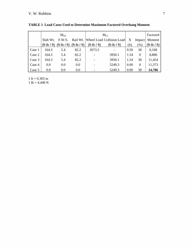
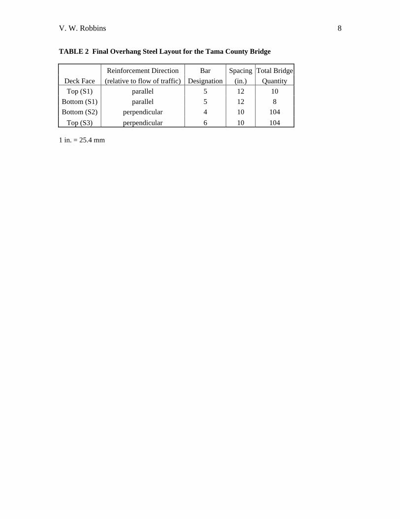
Once the live load moments had been calculated, the factored design moment was determined. The AASHTO code was not clear if the impact factor should be included with the horizontal collision force, therefore both cases were investigated. The combinations of the vertical wheel load with impact, and the horizontal collision force applied either at the edge of the slab or at the centerline of the exterior girder both with and without the impact factor resulted in five load cases as seen in Table 1. Structural Design After the factored design moment was obtained, the required amount of tensile reinforcing steel was determined. This was done using traditional reinforced concrete design practices and with a concrete compressive strength of 3,500 psi (24 MPa) and design equations provided by AASHTO. The resulting tension steel layout consisted of number six bars on 10 in. (0.25 m) centers as seen in Table 2 and Figure 5. It was decided that a hook would be added to the end of the main tension reinforcement so it could be spliced with the shrinkage and temperature steel on the bottom face.
Fatigue of the tension steel was also checked using the dead live load moments from the vertical wheel load. The impact load may have controlled the ultimate load design however for fatigue purposes, the wheel load was a more practical application. Next, AASHTO requires that the distribution of the flexural reinforcement be checked to control the amount of flexural cracking. Finally, the design moment capacity was checked to ensure that it was at least 120 % the magnitude of the cracking moment based on the modulus of rupture. The final designed deck overhang met the various AASHTO requirements described above.
In addition to the requirements for the main tension steel, AASHTO requires shrinkage and temperature reinforcement. A minimum required steel area of 0.125 in.2 per ft (0.25 cm2 per m) must be present on an exposed concrete face in each direction. Table 2 summarizes the final steel layout for both faces and directions. All directions meet the minimum shrinkage and temperature requirements.
V. W. Robbins 4
FUTURE PROJECT WORK The finalized plans and the SP for the TCB have been submitted and the expected letting date is October 21st, 2003. Construction is anticipated to begin in the spring of 2004.
The next phase of this project will be the construction documentation. This will involve written and photographic documentation of the construction process relating to the SFD. The documentation will cover the trial FRC batch required by the SP, the repositioning of the girder lines to the final spacing, installation of the transverse steel straps, placement of the internal reinforcement on the overhang, and the field-testing and placement of the FRC deck concrete. The documentation will hopefully provide valuable information for future SFD designers. The BEC will also be present, when possible, to provide technical assistance to the Iowa DOT and Tama County Engineer.
Once the construction has been completed, the BEC will participate in a series structural health monitoring tests over a two-year period. The tests will provide an opportunity to evaluate the SFD’s structural performance and durability or resistance to deterioration. The SFD will not contain any tension steel therefore the tensile strains in the FRC will be of particular interest. Measuring the strains in the transverse steel straps will provide the magnitude of the steel strap force. The load testing will also help determine the load distribution properties of the SFD by measuring the stains girder bays adjacent to the wheel load application. Three additional load tests will be conducted in the two year evaluation period after construction is completed. This will allow the BEC to identify any changes in the structural performance and load distribution properties of the SFD and also provide an evaluation of the SFD deterioration. CONCLUSIONS The design of the TCB and the construction of other SFD’s have shown that this system can be a potential cost-effective alternative to a conventional reinforced concrete deck. The design process is based on a simple engineering concept of in internal arching of the concrete and takes very little time to design with the guidance of the CHBDC. It is expected that a significant savings in the field construction can be realized with the reduction in the quantity of reinforcing steel and the labor required for placement. There will be additional costs associated with the SFD such as the fibrillated polypropylene fibers for the deck concrete and the associated costs of the transverse steel strap. However, it is anticipated that savings associated with reduced future maintenance and deck replacement costs will offset these costs. ACKNOWLEDGMENTS The BEC at ISU greatly appreciates the financial support provided by the FHWA to help introduce this potentially cost-effective bridge deck alternative into the American transportation system. The assistance and cooperation of both the Iowa DOT as well as Tama County, Iowa have proved to be extremely insightful and helpful.
V. W. Robbins 5
References
1. Thornburn, J., and A. Mufti. Design Recommendations for Externally Restrained Highway Bridge Decks. Journal of Bridge Engineering, July/August 2001, pp. 243-249.
2. Bakht, B., and A. Mufti. Steel-Free Bridge Decks Defy Corrosion. The Aderdeen Group of Hanley-Wood, Inc., 2000, pp. 1-4.
3. Canadian Highway Bridge Design Code, 1st edition, Toronto, Ontario, Canada. December 2000.
4. Ventura, C., and S. Cook. Testing of a Steel-Free Concrete Bridge. Experimental Techniques, November/December 1998, pp. 39-42.
5. Mufti, A., L. Jaeger, B. Bakht, and L. Wegner. Experimental Investigation of Fibre-Reinforced Concrete Deck Slabs Without Internal Steel Reinforcement. Canadian Journal of Civil Engineering, Vol. 20, 1993, pp. 398-406.
6. AASHTO (American Association of State Highway and Transportation Officials), Standard Specifications for Highway Bridges, 16th edition, Washington, D.C., 1996.
7. Newhook, J., and A. Mufti. A Reinforcing Steel-Free Concrete Deck Slab for the Salmon River Bridge. Concrete International, June 1996, pp. 30-34
8. Commentary on the Canadian Highway Bridge Design Code, 1st edition, Toronto, Ontario, Canada. May 2001.
9. Banthia, N., and A. Dubey. Measurement of Flexural Toughness of Fiber-Reinforced Concrete Using a Novel Technique – Part 1: Assessment and Calibration. ACI Materials Journal, November/December 1999, pp. 651-656.
10. Banthia, N., and A. Dubey. Measurement of Flexural Toughness of Fiber-Reinforced Concrete Using a Novel Technique – Part 2: Performance of Various Composites. ACI Materials Journal, January/February 2000, pp. 3-11.
11. Toutanji, H. Properties of Polypropylene Fiber Reinforced Silica Fume Expansive-Cement Concrete. Construction and Building Materials, Vol. 13, No. 4, August 1999, pp. 171-177.
12. Nagabhushanam, M. V. Ramakrishnan, and G. Vondran. Fatigue Strength of Fibrillated Polypropylene Fiber Reinforced Concretes; In Transportation Research Record 1226, TRB, National Research Council, Washington, D.C., 1989, pp. 36-47.
13. Ramakrishnan, V., G. Wu, and G. Hosalli. Flexural Behavior and Toughness of Fiber Reinforced Concretes; In Transportation Research Record 1226, TRB, National Research Council, Washington, D.C., 1989, pp. 69-77.
14. ACI Committee 544, State-of-the-Art Report on Fiber Reinforced Concrete. Report 544.1R-96. American Concrete Institute, November 1996.
15. ACI Committee 544, Measurement of Properties of Fiber Reinforced Concrete. Report 544.2R-89. American Concrete Institute, 1989.
16. Bayasi, Z., and J. Zeng. Properties of Polypropylene Fiber Reinforced Concrete. ACI Material Journal, November/December 1993, pp. 605-610.
17. Bayasi, Z., and T. Celik. Application of Silica Fume in Synthetic Fiber-Reinforced Concrete; In Transportation Research Record 1382, TRB, National Research Council, Washington, D.C., 1993, pp. 89-98.
18. AISC (American Institute of Steel Construction, Inc.), Manual of Steel Construction, Load and Resistance Factor Design, 2nd edition, Chicago IL, 1998.
19. ASTM C 995-94 - Standard Test Method for Time of Flow of Fiber-Reinforced Concrete Through Inverted Slump Cone, Annual Book o f ASTM Standards, Vol. 04.02 Concrete and Aggregates, 1996, pp. 491-492.
20. Ozyildirim, C., C. Moen, and S. Hladky. Investigation of Fiber-Reinforced Concrete for Use in Transportation Structures; In Transportation Research Record 1574, TRB, National Research Council, Washington, D.C., 1996, pp. 63-70.
V. W. Robbins 6
List of Tables
1. Load Cases Used to Determine Maximum Factored Overhang Moment 2. Final Overhang Steel Layout for the Tama County Bridge
List of Figures
1. Corrosion of Reinforcing Steel and the Corresponding Deck Concrete Deterioration. 2. Cross Section of a Typical Steel Free Deck (modified from Ventura, 1998 (5)). 3. The Tama County Bridge to be used for the First Known Steel Free Deck in the United
States. 4. Steel Strap and Transverse Diaphragm Layout for the Tama County Bridge. 5. Typical Cross Section of the Tama County Bridge.
V. W. Robbins 7
TABLE 1 Load Cases Used to Determine Maximum Factored Overhang Moment