Page 1
Design of a steel structure for a large span roof
with emphasis on the verification of bolted connections
David Alexandre Ferreira Ivo
Thesis submitted in partial fulfilment of the requirements for the degree of Master of Science in
Civil Engineering
Supervisor: Professor Pedro Antonio Martins Mendes
Examination Committee
Chairman: Professor Jorge Miguel Silveira Filipe Mascarenhas Proença
Supervisor: Professor Pedro Antonio Martins Mendes Member of the Committee: Professor José Joaquim Costa Branco
de Oliveira Pedro
July 2016
Page 2
ii
Abstract
The main objective of the thesis is the conceptual and detailed design of a steel structure for large span
roofing by means of lattice girders.
These procedures include a conceptual analysis of a proposed roofing system (36x56 meters) as well as
the detailed checking of the members and connections in accordance to EN 1993. For the purpose of
analysis, the structure is modelled with the software SAP2000 as a series of 2D structures, effectively
simulating the path of forces in the structure.
Regarding the connections, focus is given to detailed design under ultimate limit state of gusset plates as
well as spliced plate connections used for chord continuity. Serviceability is evaluated in terms of overall
deflection and taking into account the effects of slack recovery.
Key-words: Lattice girders, bolted joints, large span roofs
Page 4
iv
Resumo
O trabalho tem por objetivo a conceção e dimensionamento de uma estrutura metálica para uma
cobertura de grande vão utilizando estruturas reticuladas de aço.
Para o efeito, o trabalho envolve a conceção duma estrutura triangulada, com perfis laminados a quente,
para cobertura dum vão grande (36x56) e, posteriormente, a verificação da segurança dos principais
elementos, sistema de contraventamento e ligações, assim como do estado limite de deformação de
acordo com a EN 1993. Por forma a ter em conta o encaminhamento das cargas nos vários elementos
estruturais, foi elaborada uma sequência de modelos 2D usando o programa de cálculo SAP2000.
Neste contexto, é dado destaque ao dimensionamento e pormenorização de juntas com ligações
aparafusadas e recurso a chapas gousset; em relação ao estado limite de deformação, é avaliado o
efeito das folgas no caso das ligações aparafusadas.
Palavras chave: Estruturas reticuladas, juntas aparafusadas, coberturas de grande vão
Page 6
vi
Acknowledgements
This thesis is the product of an increasing knowledge through the many hours of work during these
years at IST. I am indebted to my Supervisor, Professor Pedro Mendes, for his guidance, always rich
with friendly and constructive criticism without whom the elaboration of thesis would not be possible. In
addition to Professor Pedro Mendes, I must also refer that Professors Luís Guerreiro, José Oliveira
Pedro, Rita Bento and Luís Castro, were among the most important and influential professors during
the degree and from whom I have learnt a great deal. I dare not list the many others to whom I am
indebted, less I do some injustice by inadvertently omitting their names. But I cannot refrain from
mentioning my mother Stella, brother Tiago and uncle and aunt José and Teresa for their love and
support as well as their willingness to accept nothing less than my full commitment to the degree I
endeavoured to.
Page 7
vii
1 Contents
1. Introduction .................................................................................................................................1
1.1 General historical overview ..................................................................................................1
1.2 Main objectives and framework ............................................................................................2
2 Trusses in single story buildings ..................................................................................................3
2.1 Main functions .....................................................................................................................3
2.2 Truss layouts .......................................................................................................................3
2.3 Roof structures ....................................................................................................................5
2.3.1 General geometry ........................................................................................................5
2.3.2 Cross-sections of members ..........................................................................................5
3. Adopted solution .........................................................................................................................7
3.1 General overview .................................................................................................................7
3.2 Members and materials .......................................................................................................8
3.3 Connections ........................................................................................................................9
3.3.1 General overview .........................................................................................................9
3.3.2 Main truss to columns ................................................................................................ 10
3.3.3 Continuity of the chords.............................................................................................. 11
3.3.4 Diagonals to chords ................................................................................................... 11
4. Design Loads and Modelling ..................................................................................................... 13
4.1 Loads ................................................................................................................................ 13
4.1.1 Dead Load (DL) ......................................................................................................... 13
4.1.2 Live load (LL) ............................................................................................................. 13
4.1.3 Snow load (SN) .......................................................................................................... 13
4.1.4 Wind load (WL) .......................................................................................................... 13
4.1.5 Load Combinations .................................................................................................... 15
4.2 Modelling ........................................................................................................................... 16
4.2.1 General overview ....................................................................................................... 16
4.2.2 Stiffness and secondary forces................................................................................... 17
4.2.3 Clearance and deflection ............................................................................................ 19
5. Verification of Members ............................................................................................................. 23
5.1 Members in Compression .................................................................................................. 23
Page 8
viii
5.2 Members in Tension .......................................................................................................... 33
6 Verification of Connections ........................................................................................................ 37
6.1 Detailed design of KT joint No. 10 ...................................................................................... 37
6.1.1 Loads and general geometry ...................................................................................... 37
6.1.2 Gusset to chord.......................................................................................................... 39
6.1.3 Diagonals to gusset.................................................................................................... 42
6.2 Detailed design of a continuous chord connection using a splice plate ............................... 65
6.2.1 Loads and general geometry ...................................................................................... 65
6.2.2 Web component ......................................................................................................... 67
6.2.3 Flange component ..................................................................................................... 73
7 Conclusion and Future Developments ....................................................................................... 79
7.1 General Conclusions ......................................................................................................... 79
7.2 Future Developments......................................................................................................... 79
7 References................................................................................................................................ 80
Page 9
ix
List of Figures
Figure 1 – Camille Polonceau truss (left); Robert Stephenson’s locomotive roundhouse (right) ............2
Figure 2 – General layout of the roof structure .....................................................................................7
Figure 3 – Main truss and member numbering.....................................................................................8
Figure 4 – Layout of the bracing truss (upper) and main truss (lower); (Dimensions in [m]) ..................8
Figure 5 – Connection concept for the lower chord ............................................................................ 10
Figure 6 – Spliced connection (left); end-plate connection (right) ....................................................... 11
Figure 7 – Bolted gusset to T chord (left); welded gusset to H or I chord flange (centre); welded
gusset to H or I chord web (right) ...................................................................................................... 12
Figure 8 – Model of the bracing truss. ............................................................................................... 17
Figure 9 – Model of the main truss .................................................................................................... 17
Figure 10 – Different layouts for the chords: standing up (left) and flat (right) ..................................... 18
Figure 11 –Bending diagram for standing up layout. .......................................................................... 18
Figure 12 – Taking up slack under gravity loading (dimensions in [mm]) ............................................ 20
Figure 13 – Unit load applied on truss ............................................................................................... 21
Figure 14 – Bracing truss loading under LL combination in ULS (forces in [kN]) ................................. 31
Figure 15 – Net areas ....................................................................................................................... 34
Figure 16- Location of joint No. 10 ..................................................................................................... 37
Figure 17 – General layout of joint No 10 .......................................................................................... 38
Figure 18 – Gusset to chord eccentricity detail .................................................................................. 38
Figure 19 – Design stresses on the gusset in front of welds ............................................................... 40
Figure 20 – Design global forces and cross-sections of gusset .......................................................... 42
Figure 21 - Positioning of bolts in diagonal 17 connecting to the gusset (dimensions in [mm]) ............ 45
Figure 22 – Whitmore cross-section and buckling length ................................................................... 46
Figure 23 – Loading on bolts (forces in the {h’, v’} system) - regarding the gusset .............................. 49
Figure 24 – Loading on bolts (forces in the {h, v} system) - regarding the gusset ............................... 50
Figure 25 - Loading on bolts (forces in the {h’, v’} system) - regarding the angle ................................ 53
Figure 26 – Positioning of bolts in diagonal 13 connecting to the gusset (dimensions in [mm]) ........... 56
Figure 27 - Whitmore cross-section ................................................................................................... 56
Figure 28 - Loading on bolts (forces in the {h’, v’} system) - regarding the gusset .............................. 58
Figure 29 - Loading on bolts (forces in the {h, v} system) - regarding the gusset ................................ 58
Figure 30 – Definition of block tearing areas - regarding the gusset ................................................... 63
Figure 31 - Definition of block tearing areas - regarding the angle ...................................................... 64
Figure 32- Location of the spliced connection in the lower chord (in red)............................................ 65
Figure 33 - Positioning of plates and holes in the spliced connection ................................................. 65
Figure 34 – Statically equivalent forces at the centre of gravity of the flange bolt group...................... 67
Figure 35 - Loading on bolts - regarding the web ............................................................................... 68
Figure 36 - Loading on bolts - regarding the plate .............................................................................. 68
Figure 37 - Block tearing area - regarding the web component .......................................................... 71
Page 10
x
Figure 38 - Block tearing area - regarding the flange component ....................................................... 71
Figure 39 - Loading of bolts in reference system {h, v} - regarding the flange ..................................... 74
Figure 40 – Block tearing - regarding the flange ................................................................................ 77
Figure 41 – Concentric and eccentric block tearing regarding the plate .............................................. 78
Page 11
xi
List of Tables
Table 1 – Considered steel properties .................................................................................................8
Table 2 – List of members of the roof structure ....................................................................................9
Table 3 – List of bolts used in the connections.....................................................................................9
Table 4 – Advantages of welded and bolted connections .....................................................................9
Table 5 – List of connections in the roof structure .............................................................................. 10
Table 6 – Live loads on roof category H ............................................................................................ 13
Table 7 – Evaluation of the characteristic snow load .......................................................................... 13
Table 8 – Evaluation of the characteristic wind pressure .................................................................... 14
Table 9 – Wind pressure (in kN/m2) for each zone of the roof, for wind direction θ=0º and 5º slope .... 14
Table 10 - Wind pressure [in kN/m2] for each zone of the roof, for wind direction θ=90º and 5º slope . 14
Table 11 – Summary of the partial factors for ULS............................................................................. 15
Table 12 – Summary of the partial factors for SLS (frequent combinations) ....................................... 15
Table 13 – Bending moment [in kN.m] comparison between rigid and pinned diagonals with different
chord layouts .................................................................................................................................... 18
Table 14 – Axial force [in kN] comparison between rigid and pinned diagonals with different chord
layouts .............................................................................................................................................. 19
Table 15 – Axial forces due to the point load (for each pair of members, the sum of the axial forces is
presented) ........................................................................................................................................ 21
Table 16 - Design checklist for members in compression................................................................... 23
Table 17 – Design forces on the gusset and angle (diagonal member 17) ......................................... 24
Table 18 – Design normal stresses and stress ratio ........................................................................... 24
Table 19 – Effective area relative to the parallel (outstanding) leg and perpendicular (internal) leg..... 25
Table 20 – Checking of cross-sectional resistance ............................................................................ 25
Table 21 – Checking of flexural buckling under uniform compression ................................................ 26
Table 22 – Buckling in between battens under uniform compression ................................................. 27
Table 23 – Verification of flexural buckling under uniform compression and bending .......................... 27
Table 24 – Design forces for the upper chord of the main trusses ...................................................... 28
Table 25 – Classification of the cross-section under uniform compression ......................................... 28
Table 26 – Effective area of both the web and the flanges ................................................................. 29
Table 27 - Effective elastic modulus .................................................................................................. 29
Table 28 – Flexural buckling under uniform compression................................................................... 29
Table 29 – Verification of flexural buckling resistance under bending and axial compression ............. 30
Table 30 – Design forces for the upper chord of the bracing trusses .................................................. 31
Table 31 - Classification of the cross-section under uniform compression .......................................... 31
Table 32 – General resistance of the cross-section under compression and bending ......................... 32
Table 33 – Flexural buckling under bending and axial compression ................................................... 32
Table 34 – Verification of resistance to flexural buckling under bending and axial compression ......... 32
Table 35 – Design checklist for tension members .............................................................................. 33
Page 12
xii
Table 36 – Design forces at the joint and mid-span ........................................................................... 33
Table 37 – Tension and bending resistance ...................................................................................... 34
Table 38 – Checking regarding the normal stress .............................................................................. 34
Table 39 – Checking regarding net area resistance ........................................................................... 34
Table 40 – Design forces on the lower chord of the main trusses....................................................... 35
Table 41 – Cross sectional resistance under tension and bending ..................................................... 35
Table 42 – Internal forces at joint No 10 (LL combination in ULS) ...................................................... 37
Table 43 – Design forces on the bracing members - diagonals (1 and 3) and post (2) (Note: Positive
values correspond to tension forces) ................................................................................................. 38
Table 44 – Design checklist for gusset to chord connection ............................................................... 39
Table 45 – Design forces for checking of gusset to chord connection ................................................ 39
Table 46 – Properties of the plate cross-section and design value of normal and shear stresses ....... 40
Table 47 – Design value of the weld forces per unit length ................................................................ 41
Table 48 – Design shear stress resistance and effective throat thickness of the welds ....................... 41
Table 49 - Design checklist for verification of resistance of the gusset ............................................... 42
Table 50 – Areas of the gusset cross-sections................................................................................... 43
Table 51 – Design shear force and checking on cross-section 1 (‘) .................................................... 43
Table 52 – Design normal force and checking on cross-section 1 (‘) .................................................. 43
Table 53 – Design shear force and checking on cross-section 2 (‘’) ................................................... 44
Table 54 – Design normal force and checking on cross-section 2 (‘’) ................................................. 44
Table 55 – Design checklist for connection of diagonal 17 to gusset .................................................. 45
Table 56 – Cross-sectional properties, design forces and checking ................................................... 46
Table 57 – Buckling length and moment of inertia about the weak axis .............................................. 47
Table 58 - Design normal forces and checking .................................................................................. 47
Table 59 - Design shear forces in the reference system {h’,v’} - regarding the gusset ........................ 49
Table 60 - Design shear forces in the reference system {h, v} - regarding the gusset......................... 50
Table 61 – Design bearing resistance, regarding the gusset, for the horizontal component ................ 51
Table 62 - Design bearing resistance, regarding the gusset, for the vertical component ..................... 51
Table 63 – Design slip resistance - regarding the gusset ................................................................... 52
Table 64 – Individual checking of the bolts (bearing and slip resistance - regarding the gusset) ......... 52
Table 65 – Design shear forces in the reference system {h’,v’} - regarding the angle ......................... 53
Table 66 – "Horizontal" component of the design bearing resistance, regarding the angle. ................ 54
Table 67 – "Vertical" component of the design bearing resistance, regarding the angle ..................... 54
Table 68 – Design slip resistance - regarding the angle ..................................................................... 54
Table 69 – Individual checking of the bolts (bearing and slip resistance - regarding the gusset) ......... 55
Table 70 – Design checklist for connection of diagonal 13 to gusset .................................................. 55
Table 71 – Cross-sectional properties, design forces and checking ................................................... 57
Table 72 - Design shear forces in the reference system {h’,v’} - regarding the gusset ........................ 57
Table 73 - Design shear forces in the reference system {h,v} - regarding the gusset .......................... 58
Table 74 - Design bearing resistance, regarding the gusset, for the horizontal component ................. 59
Page 13
xiii
Table 75 - Design bearing resistance, regarding the gusset, for the vertical component ..................... 59
Table 76 – Design slip resistance - regarding the gusset ................................................................... 59
Table 77 – Individual checking of the bolts (bearing and slip resistance - regarding the gusset) ......... 60
Table 78 – Design shear forces in the reference system {h’,v’} - regarding the angle ......................... 60
Table 79 – "Horizontal" component of the design bearing resistance, regarding the angle ................. 60
Table 80 – "Vertical" component of the design bearing resistance, regarding the angle ..................... 61
Table 81 – Design slip resistance - regarding the angle ..................................................................... 61
Table 82 - Individual checking of the bolts (bearing and slip resistance - regarding the angle)............ 61
Table 83 - Group of bolts checking - regarding the angle ................................................................... 61
Table 84 – Net cross-section and design force and resistance........................................................... 62
Table 85 - Check of block tearing resistance - regarding the gusset .................................................. 63
Table 86 – Check of block tearing resistance - regarding the angle ................................................... 64
Table 87 – Design forces at the spliced connection ........................................................................... 66
Table 88 – Areas of the web and flange; eccentricity in flange ........................................................... 66
Table 89 – Internal forces on the web and flange .............................................................................. 66
Table 90 - Design checklist for the web component of the chord connection ...................................... 67
Table 91 – Shear forces acting on each component (web and plate) ................................................. 68
Table 92 – Design bearing resistances of the web and plate components .......................................... 69
Table 93 – Design slip resistance regarding the web and the plate .................................................... 69
Table 94 – Individual checking of the bolts regarding the web component ......................................... 69
Table 95 – Individual checking of the bolts regarding the plate component ........................................ 70
Table 96 - Group of bolts checking regarding the web components ................................................... 70
Table 97 – Checking of net area resistance ....................................................................................... 71
Table 98 - Check of block tearing resistance - regarding the web and plate ....................................... 72
Table 99 - Design checklist for the flange component of the chord connection ................................... 73
Table 100 – Design shear forces on the bolts (regarding both the flange and plate) ........................... 73
Table 101 - Design bearing resistance for horizontal component (regarding both the flange and plate)
......................................................................................................................................................... 74
Table 102 - Design bearing resistance for vertical component (regarding both the flange and plate) .. 75
Table 103 - Design slip resistance (regarding both the flange and the plate) ...................................... 75
Table 104 - Individual checking of the bolts (regarding both the flange and plate) .............................. 76
Table 105 - Group of bolts checking regarding the flange component ................................................ 76
Table 106 – Checking of net area resistance ..................................................................................... 76
Table 107 – Block tearing resistance - regarding the flange (concentric loading)................................ 77
Table 108 – Checking of block tearing resistance - regarding the plate (concentric and eccentric
loading) ............................................................................................................................................. 77
Page 14
xiv
Symbols
Chapter 3
A gross cross-section area of bolts
d nominal bolt diameter
d0 hole diameter for bolts
E modulus of elasticity
fy yield strength for structural steel
fu ultimate strength for structural steel
fyb yield strength for bolts
fub ultimate strength for bolts
G shear modulus
Chapter 4
Cdir directional factor
Ce exposure coefficient
Cseason season factor
Ct thermal coefficient
Cz coefficient (from NP EN 1991-1-3)
c0 orography factor
cr roughness factor
Ed design value of effect of actions
Gk characteristic value of a permanent action
H height of the roof above ground
Iv turbulence intensity
kI turbulence factor
kr terrain factor
Qk characteristic value of a concentrated load
qb basic velocity pressure
qk characteristic value of a uniformly distributed load
qp peak velocity pressure
s snow load on the roof
sk characteristic value of snow load on the ground at the relevant site
vb basic wind velocity
vb,0 fundamental value of the basic wind velocity
vm mean wind velocity
z height above ground
z0 roughness length
Page 15
xv
z0,II terrain category II
µ1 shape coefficient for snow loads
γg partial factor for permanent action
γq partial factor for variable action
ψ factor for combination value of an action
Chapter 5
x-x axis along a member
y-y major axis of a cross-section
z-z minor axis of a cross-section
v-v minor axis of a cross-section (where this does not coincide with z-z)
Aa area of the angle’s cross-section
Aeff effective cross-section area
Anet net area of angle
b,eff effective width
Cay equivalent uniform moment factor
Cmz equivalent uniform moment factor
CmLT equivalent uniform moment factor
e0 maximum amplitude of a member imperfection
eN shift of the centroid of the effective area relative to the original center of gravity
Ia moment of inertia of the angle about the relevant axis
kyy interaction factor
kzy interaction factor
kσ buckling factor for plates
Lcr buckling length
Ma,Ed bending moment on the angle
Mg,Ed bending moment on the gusset
Mpl,Rd design plastic resistance to bending about the relevant axis
m number of braced elements
Na,Ed axial force on the angle
Nb,Rd design buckling resistance of a compression member
Nc,Rd design resistance of the net cross-section for uniform compression
Ncr elastic critical force for the relevant buckling mode based on the gross cross section
Ng,Ed axial force on the gusset
Npl,Rd design plastic resistance to normal forces of the gross cross-section
Nt,Rd design value of the resistance to tension force
Nu,Rd design ultimate resistance to normal forces of the net cross-section
Qp equivalent force
qd equivalent force per unit length
Va,Ed shear force on the angle
Page 16
xvi
Vg,Ed shear force on the gusset
Weff effective elastic section modulus
σa normal stress on the angle
σg normal stress on the gusset
αm reduction factor to assess the equivalent stabilizing load
γM0 partial factor for resistance of cross-sections whatever the class is
γM1 partial factor for buckling resistance of members
γM2 partial factor for resistance of cross-section in tension
Ψ stress ratio
ϕi value to determine the imperfection factor χ
λi non dimensional slenderness about the relevant axis
λp plate slenderness
ρ reduction factor for plate buckling
χi reduction factor about the relevant axis
Chapter 6
Af,net net area in the flange component
Ag area of the gusset’s cross section
Ann net area subjected to shear
Ant net area subjected to tension
Ap,net net area in the plate component
Aw,net net area in the web component
amin minimum throat thickness
bi number of the bolt
e1 end distance from the center of bolt hole to the adjacent end of any part
e2 edge distance from the center of bolt hole to the adjacent edge of any part
ef eccentricity from the edge of the flange to the center of the bolt group
Fb,Rd design bearing resistance per bolt
FM,bi design shear force on each bolt due to the acting moment
FM,bi,h’ component along axis h’ of the design shear force on each bolt due to the acting moment
FM,bi,v’ component along axis v’ of the design shear force due on each bolt to the acting moment
FN,bi design shear force on each bolt due to axial force on the gusset~
Fp,C design value of pre-loading force
Fs,Rd design slip resistance per bolt
FV,bi,Ed design shear force on each bolt
FV,bi,h’,Ed component along axis h’ of the design shear force on the gusset due to axial force
FV,bi,h,Ed component along axis h of the design shear force on each bolt
FV,bi,v’,Ed component along axis v’ of the design shear force on the gusset due to axial force
FV,hi,v,Ed component along axis v of the design shear force on each bolt
FV,Rd design shear resistance per bolt
Page 17
xvii
FV,Ed,w design shear force acting on the bolt group on the web
FV,Ed,p design shear force acting on the bolt group on the flange
Fw design value of the weld force per unit length
Fw,h design value of the weld force per unit length, horizontal component
Fw,v design value of the weld force per unit length, vertical component
fvw,d design value of the shear strength of the weld
hi’ distance from the center of gravity of the bolt group to bolt bi along the axis h’
Ig moment of inertia about the minor axis of the gusset cross section
K Thornton factor
Mf design bending moment acting on the flange of the chord in a spliced connection
Nf design force acting on one flange of the chord in a spliced connection
Nf,net,Rd design force acting on the net area of the flange component
Ni,g,bt,Ed design acting normal force on the gusset.
Np,net,Rd design force acting on the net area of the plate component
Nw design force acting on the web of the chord in a spliced connection
Nw,net,Rd design force acting on the net area of the web component
n number of friction surfaces
nb number of bolts resisting in a line of action for net cross-section
nbt total number of bolts in a connection for net cross-section resistance
p1 spacing between the centers of bolts in a line in the direction of load transfer
p2 spacing perpendicular to the load transfer direction between adjacent lines of bolts
ri’ distance from the center of gravity of the bolt group to bolt bi
t thickness of the plate
Veff,1,Rd design block tearing resistance for a symmetric bolt group subjected to concentric loading
Veff,2,Rd design block tearing resistance for a symmetric bolt group subjected to eccentric loading
Vf design shear force acting on the flange of the chord in a spliced connection
vi’ distance from the center of gravity of the bolt group to bolt bi along the axis v’
zg vertical distance from the centroid of gusset cross section to the outmost fiber
τg elastic shear stress in the gusset cross section
µ slip factor
Page 19
1
1. Introduction
1.1 General historical overview
In every structural engineer’s first course in statics the concepts needed to analyse statically determinate
structures are defined. Apart from the simply supported beam, the truss stands as the backbone of
structural engineering.
The concepts needed to analyse these structures were largely developed in the seventeenth and
eighteenth century by the likes of Galileo, Stevin, Newton, Varignon, Bernoulli, Euler, Lagrange and
others.
It was in France, during the nineteenth century, that advanced mathematical and scientific concepts
related with civil engineering began to be taught, to the Ingéniurs of Ecole des Ponts et Chaussées and
Ecole Polytechnique. One can find the first mathematical analyses of trusses in Navier’s 1826 “Résumé
de Leçons Données à L’Ecole des Ponts et Chaussées sur l’Appication de la Mécanique” [1]. Navier
determined the forces in simple statically determined trusses as well as in statically indeterminate trusses,
but it was the analogy between forces in beams and forces in chords that perhaps had the greatest
influence on the design of trusses. By noticing that trusses with parallel chords could be treated as beams
with stiffness proportional to the area of both chords multiplied by the distance between them, the
formulas of Navier greatly expanded design practices and were later incorporated in the 1830’s and
1840’s designs of American wooden truss bridges.
Indeed, engineers such as Stephen Long, William Howe, James Warren, Thomas Pratt and many others
greatly understood the teachings of Navier and successfully applied them both in timber and iron
structures. Further dissemination of Navier’s work in the United States is due to Dennis Mahan, who in
1837 published his textbook “An Elementary Course of Civil Engineering for Use of the Cadets of the
United States Military Academy” and states in the introduction that “the best counsel that the author could
give to every young engineer, is to place in his library every work of science to which Mr. Navier’s name is
in any way attached” [1].
In Europe and in the United States, trusses were first adopted as roofs structure rather than bridges. In
France, Camille Polonceau patented a truss in 1837, displayed in Figure 1 (left), that was used in the
terminals for the railroad from Paris to Versailles [1]. In Britain, a lasting example of roof truss design of
this period is Robert Stephenson’s locomotive roundhouse, Figure 1 (right), designed for the Birmingham
railway.
Page 20
2
Figure 1 – Camille Polonceau truss (left); Robert Stephenson’s locomotive roundhouse (right)
In its essence, a truss is framed structure in which members are connected at their ends forming a
triangulated system, arranged in a pre-determined pattern depending on the span, type of loading and
general function. The members are subjected to essentially axial forces due to externally applied loads at
each node. Where these loads lie in the same plane one may consider a plane truss, or where loads may
act in any direction, in which case one should consider space trusses so that members can be oriented in
three dimensions. From a theoretical standpoint, the members are assumed to be connected to the joints
so that rotation is permitted, and thereby it follows from equilibrium that the individual structural members
act as bars – carrying solely axial force either in compression or tension. Often, joints are detailed such
that free rotation does not occur, in which case the hinged property of the joint is an assumption. Even if
so, the approximation is valid - to be discussed further on – which greatly simplifies the manual analysis of
the forces in the structure and undoubtedly contributed for their popularity in bridges and roof structures,
and later in cranes, offshore structures, high rise buildings and many other.
1.2 Main objectives and framework
The main objective, as stated in the Abstract is the conceptual and detailed design of a steel structure for
large span roofing by means of lattice girders.
In chapter 1, a historical overview of truss structures is outlined. This serves as an introduction to how
these type of structures emerged in our society and why they became so popular.
In chapter 2, general aspects relating to geometry and type of cross sections used for trusses in single
story buildings are discussed.
In chapter 3, starts by presenting a design layout for the roof structure. Further discussion follows, where
general considerations of the type of connections existing in the structure are made.
In chapter 4 the loads and finite element model are determined and a brief analysis of the effect of slack is
considered.
In chapter 5 and 6 the safety checking of the elements and connections are carried out.
Page 21
3
2 Trusses in single story buildings
2.1 Main functions
In single story buildings, namely industrial buildings, airplane hangars, sports pavilions, stadiums etc.,
trusses are usually used for two main purposes. First, to provide a path by which the loads (gravity, wind
etc.) can discharge on the columns. Second, to provide lateral stability to the series of portal trusses.
These are known as bracing trusses, which can be longitudinal or transverse to the series of portal
trusses; the bracing systems can be introduced on the roof and in the side walls such that the loads can
find a viable path to discharge at the foundation.
2.2 Truss layouts
There are many possible layouts for trusses in single story buildings. A short list is presented bellow
outlining the main attributes of each one.
Pratt truss 1) 2)
:
Regarded as cost effective structures, these
trusses are used where gravity loads are
dominant, as such all the diagonal members
are in tension and the posts are in
compression.
For predominant uplift forces, as it may be the
case in open buildings, inverted diagonals are
used and the resulting force in them is tension.
(a) Original Warren truss
(b) Modified Warren truss
Warren truss1) 2)
:
The diagonals in these trusses are alternatively
in compression and in tension, providing a
good solution for distributed loads.
Where vertical posts are not used (a), these
trusses have about half the number or joints
and brace members when compared with
Pratt’s solution. Where vertical posts are used
(b) a few observations should be noted. First
these additional vertical members exist mainly
to control high compression of the chords as it
reduces the buckling length of these members.
Secondly they provide a path of for loading by
purlins that can exist at intermediate points. In
Page 22
4
the case were these intermediate purlins do
not exist, these additional vertical posts will
have zero axial force.
If CHS/RHS members are used there are
considerable opportunities to use gap joints as
the layout is more open. Additionally, these
members provide good resistance to
compression.
X truss1) 2)
:
These trusses are commonly used as wind
girders. One can design such structures
considering the diagonals as compression
resistant, in which case the truss is a
superposition of two Warren trusses, or
alternatively by ignoring the members in
compression in which case the behaviour is
that of the Pratt truss.
Additional members1) 2)
:
Additional members are adopted primarily to
reduce the buckling length of members in
compression. Another reason for these
additional members is the added loading points
that are established therefore avoiding
additional bending to the chords.
Slope1) 2) 3)
:
For all of the above structures, slope may be
provided to fit architectural demands or to
guarantee the drainage of the upper cladding.
Either simple or double slope may be provided
to the upper chord.
Fink truss3)
:
The most common use of this type of trusses is
in the roof structure of residential low density
housing.
1) May be used either in portal trusses – transmitting bending moments to the columns – or in simply supported trusses.
2) Adequate for spans that range from 20 to 100 meters. [3]
3) Adequate as simply supported and with spans that range from 10 to 15 meters.
Page 23
5
2.3 Roof structures
2.3.1 General geometry
Focusing on roof structures, those that span more than 20 – 25 meters are often more economical if
designed as trusses instead of portal frames [2]. Savings stem from the fact that trusses are lighter, using
less steel, than solid profiles. Indeed, for the same weight, better performance in both of resistance and
stiffness is managed when considering trusses. Although aesthetics is a matter of taste, the general
consensus is that trusses are of a superior appearance when compared to portal frames. However,
relating to the installation process, hot rolled beams are less time consuming as they have much fewer
connections. For a cost effective truss, the engineer has to balance several aspects such as equipment,
man-hours, and cost of steel.
As with beams, the ratio depth to span of flat trusses at mid span, otherwise known as slenderness,
should range from 1/7.5 to 1/12 [2] so that good structural performance, regarding deflection and forces
on each element, is achieved. Moreover, efficient layouts should consider point loads applied only at
nodes with diagonals connecting with chords at 35º to 55º. The reason behind these two numbers is a
simple one. As the inclination of each diagonal increases (becoming more vertical) so will the number of
total diagonals in the truss. Thus, for the same loading, the axial force on each element will decrease
making the case for savings by means of a less robust cross-section. Evidently, the validity of this line of
thought breaks down when the total number of additional diagonals and connections result in such
additional cost that the savings in material are outweigh.
2.3.2 Cross-sections of members
There are two main families of cross-sections used in truss members: open sections and closed sections.
Open sections offer greater ease to establish connections as they require little to no welding, resorting
primarily to bolts. For small to intermediate spans, a popular design is using single angles for diagonals
and T profiles for chords. In this choice of design, it is recommended that vertical and diagonal members
be placed on the same side of the T section as to avoid additional bending of the web and twisting of the
chords [2]. For large spans and member forces, a popular design is using double angles or channels
back-to-back spaced intermediately with battens for the diagonal members and I or H profiles (i.e. IPE,
HEA, HEB) for the chords. The chords can be placed either vertically (standing up) or horizontally (flat). In
both layouts there are advantages to be noted. First, in the horizontal layout the obvious advantage is
that, for chords in compression, it is easier to increase in-plane buckling resistance, by shortening the
buckling length by means of additional diagonals, than to increase out-of-plane buckling resistance. In the
vertical orientation, the advantage stems from the fact that it is easier to establish a connection between
the purlins and chord.
Page 24
6
Closed sections have several advantages that need mentioning. Primarily, CHS and RHS sections are
much more efficient cross-sections under compression when compared with open cross-sections. The
radius of gyration is the same in all directions, hence greater efficiency. They are considered to be more
aesthetic and are generally better appreciated by the public at large. As maintenance is regarded, tubular
trusses require less paint per linear meter [2], reducing the cost of the corrosion protection treatment
Page 25
7
3. Adopted solution
3.1 General overview
In deciding the appropriate layout of a roof structure the major problem is to find the right balance between
economy and structural efficiency. There is little difficulty in assuming a truss structure instead of a I
beam as it has already been noted that with increasing spans the latter become less efficient. Other
questions arise such as what is the ideal spacing of the main trusses? What is the best slope of the
chords and should both have the same slope? What is the best layout for the different truss? Is it
preferable to have transverse or longitudinal purlins? What is the best type of cross-section to adopt?
A solution is presented in this thesis, Figure 2, bearing the principles outlined in the previous section and
giving an answer to the issues mentioned above, although not in an exhaustive manner. The global
bracing system is not indicated in Figure 2 as it is not evaluated in the document. Figures 3 and 4 display
the layout of the main truss and bracing truss with the respective dimensions.
Purlins (blue); Bracing truss (red); Main truss (black)
Figure 2 – General layout of the roof structure
36 m 14 m
Purlins are separated at 1.75 m
Page 26
8
Figure 4 – Layout of the bracing truss (upper) and main truss (lower); (Dimensions in [m])
Figure 3 – Main truss and member numbering
3.2 Members and materials
All structural steel members, including gusset plates, have the same grade of steel.
Table 1 – Considered steel properties
Members Type fy [Mpa] fu [Mpa] E [Gpa] G [Gpa]
Structural Steel S 355 355 510 210 81
The members that make up the structure are summarized in Table 2. As is shown in the table, all the
diagonals of the bracing truss have the same profile and the same is true for the main truss. The main
reason for this decision is to reduce the complexity of the installation on-site. It would be possible to adjust
the robustness of the profiles according to the internal forces but so has not been done.
Page 27
9
Table 2 – List of members of the roof structure
Structure Members Profile
Cladding - TR 45.333.1000 Negative Purlins - IPE 160 (vertical)
Bracing truss Upper & Lower chord IPE 160 (Flat)
Diagonals L 100x100x10
Main truss Upper chord IPE 600 (Flat) Lower chord IPE 400 (Flat)
Diagonals 2L 150x150x15
The connections are established by welding and bolting. For the latter, depending on where the
connection is, several types of bolts are adopted so to best fit the needed resistance.
Table 3 – List of bolts used in the connections
Type & Class fyb [Mpa] fub [Mpa] d [mm] d0 [mm] A [mm2]
Bolts
M 20 cl. 10.9 900 1000 20 22 245
M 24 cl. 10.9 900 1000 24 26 353
M 27 cl. 10.9 900 1000 27 30 459
3.3 Connections
3.3.1 General overview
Connections are perhaps the most critical of parts in the design process. Indeed often enough, the cause
of structural failure is due to poorly designed and detailed connections [3]. Modern steel structures are
connected by welding or bolting – either high-strength or standard. Rivets were common in the past, but
since the publication in 1951 of the first specification from the Council of Riveted and Bolted Structural
Joints authorizing the substitution of rivets for high strength bolts, their use has plummeted [3].
The choice between welding and bolting depends on several factors. A possible shortlist includes
customer acceptance, cost of both material and installation/execution, and safety. Welding and bolting
have their advantages that should be considered in the design process.
Table 4 – Advantages of welded and bolted connections
Welded Bolted Less sorting of materials and reduction in installation cost
Saving in transportation outweigh additional installation costs
Less staging area required Reduced manufacturing cost Less hardware and reduced chance of short shipments as fewer components are involved
Easier to reconfigure and repair
Defects in manufactured frame braces are discovered in shop when welding is applied
Easier to install on-site
Seismic base plates allow for column placement at ground level
Easier to dismantle
Page 28
10
The adopted structural design has several types of connections, these can be summarized as follows:
Table 5 – List of connections in the roof structure
Connecting members Type
Purlin to bracing truss Bolted and welded
Chord continuity in both the bracing and main truss Spliced plate with bolts
Gusset to Chord Welded
Diagonals to Gusset Bolted
Main truss to columns Bolted
Despite the interest in analysing all of the above, only the continuity chord connection, gusset to chord
and diagonals to gusset will be fully analysed in this document. Although not fully analysed, a brief
discussion on particular aspect of the connection of the main truss to the columns follows.
3.3.2 Main truss to columns
The main truss is designed as simply supported on the columns. So, one of the chord members could be
omitted (namely the first lower chord member, with the arrangement of diagonals as shown in this case);
however, it is advantageous to keep this member at the connection of the truss to the column in order to
supply lateral stability to the lower chord of the truss. Thus, in order to enable the global in-plane rotation,
the connection of one of the chords to the column must allow for relative horizontal displacement. Usually,
the horizontal displacement is released at the node where the diagonal does not meet – in this case, the
lower node.
In the truss being studied, the horizontal displacement in node B shown in Figure 5 (with no member 1-1
in the structural model) due to the gravity loads is +36 mm. Thus, a possible solution for the connection of
member 1-1 to the column is as shown in Figure 5, comprising a plate welded to the column with a hole
that has enough length (say, 50 mm) to accommodate the expected displacement.
Figure 5 – Connection concept for the lower chord
Page 29
11
3.3.3 Continuity of the chords
When designing large spans, one has to consider the maximum length of the members provided by the
fabricator. These typically limit the length at about 12 meters due to the nature of the transportation
method – trucking has limited allowable length, therefore limiting the length of profiles to be transported.
The proposed structure has a 36 meter span and therefore, in order to guaranty continuity, the connection
has to be rigid and there are several options that can be considered.
Bolted connections are usually adopted instead of welded, the reason being that welded connections
need a greater control in quality, and so better efficiency is achieved in shop rather than on site. Two
types of bolted connections are possible with different implications: end-plate and splice-plate
connections. End-plate connections are possible for I, H, and hollow profiles. Here, bolts are in tension
and, with increasing force, the transverse plates will tend to bend in a complex three-dimensional manner.
A simplified approach may be considered in the analysis of such connections, based on the so-called
‘equivalent T-stub model’. Splice-plate connections are generally used for I, H, T, L and U profiles. The
main difference from the end-plate type is that bolts are loaded with shear instead of tension.
In the adopted solution, splice-plates are considered.
3.3.4 Diagonals to chords
Depending on the assumptions considered in modelling the structure, as well as on the type of profiles
chosen as diagonals, welding and bolting may be considered. It is common to use gusset plates as
additional elements in the structure to assist in connecting diagonals to chords. These plates may be
bolted or welded to the chords and the diagonals may as well be bolted or welded to the gusset.
Figure 6 – Spliced connection (left); end-plate connection (right)
Page 30
12
For chords that are of T or U profiles a typical connection is shown in Figure 7 - left, with the gusset
connected to the chord with bolts.
Figure 7 – Bolted gusset to T chord (left); welded gusset to H or I chord flange (centre); welded gusset to H or I chord web (right)
For chords that are I or H profiles the gusset is typically connected to these through welding and the
diagonals may be bolted or welded to the chords (Figure 7 - centre and right).
The chords may be arranged vertically (standing up) or horizontally (flat), with the gusset connecting to
the flange or web respectively. The discussion on the implications of a vertical or flat layout of the chords
is provided further in section 4.2.2.
Relating to the gusset plate design and analysis, EN1993 does not give any specific indication on safety
checking of these members. In mid twentieth century, Whitmore and Thornton developed methods for
analysing cross-sectional resistance as well as buckling of gusset plates that are adopted in this
document.
Page 31
13
4. Design Loads and Modelling
4.1 Loads
The only loads considered are the dead, live, wind and snow loads. Temperature has been opted out as
the structure is modelled as a series of 2D statically determinate structures with slotted holes in the
connections.
4.1.1 Dead Load (DL)
The main components of DL on roof trusses in single story industrial buildings are the self-weight of the
following elements: cladding, purlins, chords, diagonals and connection elements such as bolts and
gusset plates.
4.1.2 Live load (LL)
The gravity load due to maintenance is regarded as the main LL on roof trusses. In accordance to EN
1991-1-1, the roof is of category H and as such the characteristic value is defined in Table 6.
Table 6 – Live loads on roof category H
qk [kN/m2] Qk [kN]
0.4 1
4.1.3 Snow load (SN)
Snow loads are quantified with the assumptions indicated in Table 7, according to NP EN 1991-1-3.
Table 7 – Evaluation of the characteristic snow load
s 2.24 [kN/m2]
sk 2.8 [kN/m2]
ce 1
Cz 0.1
ct 1
H 500 [m]
µ1 0.8
4.1.4 Wind load (WL)
Given the slope of 5º, and in accordance to EN 1991-1-4, the predominant wind load on the roof truss is
uplift force perpendicular to the roof, due to the suction effect of the wind blowing over. Hence, the wind
loads act contrary to gravity loads and with greater magnitude. To illustrate this result, Table 9 and Table
10 provide the design wind pressures in the roof (with the wind velocity and the division into zones
Page 32
14
according to NP EN 1991-1-4) already taking into account the results of Table 8 and the internal
pressures.
Table 8 – Evaluation of the characteristic wind pressure
Basic wind velocity
Mean wind
velocity
Peak velocity pressure
Exposure
coefficient
Vb [m/s] 27 Vm [m/s] 21.45 qp [kN/m2] 0.83 ce 1.829
cdir 1 cr 0.79 Iv 0.2711 qb [kN/m2] 0.456 cseason 1 co 1 KI 1 qp [kN/m
2] 0.834
vb,0 [m/s] 27 Vb [m/s] 27
kr 0.22 z [m] 12 z0 0.3 z0,II 0.05
Table 9 – Wind pressure (in kN/m2) for each zone of the roof, for wind direction θ=0º and 5º slope
F G H I J
Cp,10 Cp,1 Cp,10 Cp,1 Cp,10 Cp,1 Cp,10 Cp,1 Cp,10 Cp,1
Internal (-) -1.58 -2.25 -1.17 -1.83 -0.67 -1.17 -0.67 -0.67 0.00 0.00
-0.17 -0.17 -0.17 -0.17 -0.17 -0.17 -0.67 -0.67 -0.67 -0.67
F G H I J
Cp,10 Cp,1 Cp,10 Cp,1 Cp,10 Cp,1 Cp,10 Cp,1 Cp,10 Cp,1
Internal (+) -1.17 -1.83 -0.75 -1.42 -0.25 -0.75 -0.25 -0.25 0.42 0.42
0.25 0.25 0.25 0.25 0.25 0.25 -0.25 -0.25 -0.25 -0.25
Table 10 - Wind pressure [in kN/m2] for each zone of the roof, for wind direction θ=90º and 5º slope
F G H I Cp,10 Cp,1 Cp,10 Cp,1 Cp,10 Cp,1 Cp,10 Cp,1
Internal (-) -1.50 -2.00 -1.25 -1.83 -0.75 -1.17 -0.67 -0.67
F G H I Cp,10 Cp,1 Cp,10 Cp,1 Cp,10 Cp,1 Cp,10 Cp,1
Internal (+) -1.08 -1.58 -0.83 -1.42 -0.33 -0.75 -0.25 -0.25
Page 33
15
4.1.5 Load Combinations
The load combinations are summarized in Table 11 and Table 12, in accordance to EN 1990. As the
temperature is not considered in the model the partial safety factors are not indicated.
Ultimate Limit state (ULS)
𝐸𝑑 = ∑ 𝛾𝑔𝑖𝐺𝑖,𝑘 + 𝛾𝑞 [𝑄𝑖,𝑘 + ∑ 𝛹0𝑗𝑄𝑗,𝑘
𝑛
𝑗=2
]
𝑚
𝑖=1
Table 11 – Summary of the partial factors for ULS
Combination DL LL W S
Live Load 1.35/1.0 1.5/0.0 0.6/0.0 0.5/0.0
Wind 1.00/0.0 - 1.5/0.0 0.5/0.0
Snow 1.35/0.0 - 0.6/0.0 1.5/0.0
Serviceability limit state (SLS)
The frequent combination is adopted to verify deflection.
𝐸𝑑 = ∑ 𝛾𝑔𝑖𝐺𝑖,𝑘 + 𝛾𝑞 [𝑄𝑖,𝑘 + ∑ 𝛹0𝑗𝑄𝑗,𝑘
𝑛
𝑗=2
]
𝑚
𝑖=1
Table 12 – Summary of the partial factors for SLS (frequent combinations)
Combination DL LL W S
Live Load 1 1 0.2 0.2
Wind 1 - 1 -
Snow 1 - 0.2 1
Page 34
16
4.2 Modelling
4.2.1 General overview
As outlined in chapter 1, from the assumption of pinned joints, the members are subjected only to axial
forces. However some deviations from the theoretical model must be noted as follows:
Both diagonals and chords are frequently joined by more than one bolt – which would enable
greater freedom of rotation. When several bolts are used or where welding is applied, as is the
case with gusset plates, the restriction in rotation is considerably higher. Further, some members,
such as chords, are generally continuous over several nodes. From this, members of the truss
experience bending and shear in addition to the axial forces – these are known as secondary
internal forces; the more rigid the chords the greater these forces will be.
Loads may be applied in between nodes of the truss, resulting in bending and shear on the
chords.
Another type of secondary forces of bending and shear appear with eccentric connections of
members at joints. The magnitude of these forces depends upon the eccentricity - increasing
proportionally to size of the eccentricity.
As the load path is from the cladding to the purlins, from these to the bracing system and finally
discharging on the main truss, several 2D models are adopted with each following model loaded with the
reactions of the previous. All modelling is conducted in SAP2000.
The purlins are modelled as simply supported beams with a 5º slope. The loads applied to the purlin result
from the quantification outlined in section 4.1.
The bracing truss is modelled as a Warren truss with a continuous chords and pinned diagonals as
displayed in Figure 8. Four supports are considered so that the reactions on the main truss are distributed
between both the upper and lower chords. The loading on this truss is the self-weight of its members as
well as the reactions of the purlins.
Page 35
17
Figure 8 – Model of the bracing truss.
The main truss differs from the bracing one – a modified Warren truss is adopted with additional
members. Like the purlins, the main truss has a 5º slope. The upper and lower chords are modelled as 2
continuous bars for each slope. All the diagonal and vertical posts have moment releases at their ends –
pinned to the chords.
Figure 9 – Model of the main truss
4.2.2 Stiffness and secondary forces
In the previous section secondary forces were described as originating from essentially two different
reasons – geometric and boundary conditions. For the first, little explanation is needed as one can easily
perceive that an applied force eccentric to the centroid of a member will result in additional bending and
shear. For the latter, in particular, that with increasing stiffness of the chords increasing bending follows,
further explanation is required. The phenomenon is an interesting one and can be illustrated by comparing
the internal forces with the upper and lower chords arranged either standing up or flat.
Page 36
18
Figure 10 – Different layouts for the chords: standing up (left) and flat (right)
Under the LL combination of ULS both chords bend in the plane of the truss. In the first layout, with both
chords standing up, bending in this plane mobilizes the strong inertia of the IPEs, thus increased bending
moment when compared with the profiles layout as flat. The bending moment increases from 6.3 kN.m, to
136.5 kN.m as profiles change position from flat to vertical (22 times greater). In Figure 11 the bending
moment diagram on the chords with standing up layout is displayed.
Figure 11 –Bending diagram for standing up layout.
Analysing further the effect of member stiffness in the general behaviour of the structure, another
evaluation is considered. It has already been stated that the diagonals and posts are modelled as pinned
to the chords but in reality these are connected to a gusset plate with several pre-loaded bolts and the
gusset welded to the chord. Thus, one may assume that the connection is closer to a rigid one than to the
pinned assumption. If so, during deformation the ends of all members that connect at the node will rotate
with the same angle around the node whilst maintaining the angle between each one. To demonstrate the
viability, from the analysis standpoint, of the pinned assumption, the comparison of the bending moments
between rigid and pinned diagonals with different chord layouts is carried out (Table 13).
Table 13 – Bending moment [in kN.m] comparison between rigid and pinned diagonals with different chord layouts
Vertical Flat
End moment in diagonal 13 (rigid) 1.33 0.70
End moment in diagonal 17 (rigid) 1.55 0.67
Maximum moment due to self-weight in diagonals 13 and 17 (pinned)
3.20 3.20
136.5 kNm
Page 37
19
It is evident that the bending moment considered at the end of the diagonals with rigid connections is of
the same magnitude as the bending moments due to self-weight in the same diagonals.
Moreover, the transformation from pinned to rigid has very little influence on the axial force in the chords,
as the shear at the end of the diagonals changes only slightly the value of the axial force.
Table 14 – Axial force [in kN] comparison between rigid and pinned diagonals with different chord layouts
Boundary condition Member Vertical Flat
With rigid joints 3-2 381 408 3-3 1316 1345
With pinned diagonals and posts
3-2 381 408 3-3 1317 1346
Therefore, it is no surprise that common practice in designing trusses is to assume chord continuity with
pinned posts and diagonals.
4.2.3 Clearance and deflection
Firstly, the consequences of increased deflection should be outlined:
Discomfort is perhaps the most important as users of the building may not feel safe when noticing
slopes that are evidently not desired.
In statically indeterminate structures, additional forces arise and may place the structure at greater
risk of failure.
Increasing risk of pitch inversion follows increasing deflection of the truss. If pitch inversion does
effectively occur, water accumulation could seriously impact the building.
It is therefore evident that controlling deflection is not of minor importance.
In discussing the effect of deflection of a truss structure with bolted connections it is necessary to
distinguish between two rather different aspects that play an important role: general slenderness of the
truss and clearance of the bolts. For both these aspects the principal of virtual work is a simple yet very
convenient form of analysis. For framed structures in general and using standard notation, the principal
states that:
1𝛿 = ∑ ∫ (𝑉1𝑉′1𝐺𝐴1
+𝑉2𝑉′2
𝐺𝐴2
+𝑁𝑁′
𝐸𝐴+
𝑀1𝑀′1𝐸𝐼1
+𝑀2𝑀′2
𝐸𝐼2
+𝑇𝑇′
𝐺𝐽)
𝐿
0
𝑑𝑥3
𝑚𝑒𝑚𝑏𝑒𝑟𝑠
Page 38
20
Let us consider for the first aspect the notion understood by Navier, that a truss could be analysed as a
beam. In this scenario, where depth increases so will inertia and, consequentially, slenderness decreases.
Hence, by modifying the overall geometry of the truss as to increase its depth, one can control deflection.
However, even with an adequate depth, clearance of bolts, as unexpected as it might seem, can have a
major contribution for deflection. When bolts are in shear, for the successful transmission of the force
these have to come in contact with the adjacent members, either by their grip or by their thread. Either
way, the initial slack or clearance, that is typically 2 mm, is rearranged as the adjacent members slip,
establishing contact with the bolt – otherwise known as taking up slack. This can be assimilated to a
reduction or increase of the length of the members in compression or tension, respectively. To further
illustrate this point the main truss mentioned in chapter 3 is analysed.
The bolts in the spliced connections of the chords as well as in the connections to the gusset plates of the
diagonals are inserted in holes that are drilled with 2 mm of clearance. Assuming that the bolts are initially
installed at the centre of each hole, as self-weight comes in to action, the available clearance is readjusted
and the members experience a 4 mm extension or reduction (the transmission of forces through the
connections take place only after this readjustment). Figure 12 illustrates this phenomena for a spliced
connection between plates in tension.
Figure 12 – Taking up slack under gravity loading (dimensions in [mm])
As previously mentioned, the principal of virtual work is applied to evaluate these effects of the clearances
(i.e., the effects from the bolts taking up slack). Considering a virtual unit load applied to the truss at mid-
span, the corresponding axial forces in the members are those shown in Table 15. The virtual unit load is
applied such that the internal virtual forces have the same sign as when gravity loading is considered –
Page 39
21
members that are in compression/tension under gravity loading are also in compression/tension under the
virtual load.
Figure 13 – Unit load applied on truss
Table 15 – Axial forces due to the point load (for each pair of members, the sum of the axial forces is presented)
Member 14 + 15 8 +10 23 + 27 25 + 26 13 + 18 7 + 11 17 + 16 6 + 12 5 + 19 1 + 2 3 + 4 9
N 1.914 0.017 0.010 0.004 1.808 0.005 1.947 0.001 1.802 3.120 2.126 0.536
The internal axial deformation of each member due to the effect of taking up slack under gravity loading is
∫𝑁
𝐸𝐴𝑑𝑥3 = ±4 𝑚𝑚; thus, the vertical deflection at mid-span can be calculated as follows:
1𝛿 = ∑ ∫ (𝑁
𝐸𝐴)
𝐿
0
∙ 𝑁′ 𝑑𝑥3
𝑚𝑒𝑚𝑏𝑒𝑟𝑠
= 4 × ∑ |𝑁′|
𝑚𝑒𝑚𝑏𝑒𝑟𝑠
=
= 4 × (1.914 + 0.017 + 0.010 + 0.004 + 1.808 + 0.005 + 1.947 + 0.001 + 1.802 + 3.120 + 2.126 + 0.536)
= 53.2 𝑚𝑚
Considering that under the LL combination in SLS the total vertical deflection is 42.7 mm, this added
deflection due to the recovery of slack at the bolts is considerable; it represents roughly 125% in addition.
In order to control this additional deflection several measures may be adopted, such as:
Changing the connections by considering only welding instead of bolts;
Drilling a smaller clearance if a category A connection is chosen (i.e. drilling +1 mm or even +0.5
mm, instead of +2 mm);
Choosing pre-loaded bolts and category C connections.
If the maximum displacement, under SLS conditions, is taken as 𝛿𝑚𝑎𝑥 = 𝐿/200, the limit state would be
verified in the present case (for L = 36,00 m, 𝛿𝑚𝑎𝑥 = 180 mm). Anyway, preloaded bolts of category C are
used in all connections the presented solution, so that no deflection from recovery of slack needs be
considered.
Page 41
23
5. Verification of Members
In this chapter, the proper subject of concern is to determine the profiles that satisfy the safety checking in
accordance to EN1993. In this process, one should consider all load combinations and all critical sections
for each member. This procedure can be quite lengthy as it implies repetition of the same checking as
each load combination is considered. Therefore, and perhaps to better illustrate the principals and
checking procedures that have to be considered in the design of such structures, only some sections are
analysed under LL combination in ULS.
5.1 Members in Compression
Table 16 shows the checklist for the design of members in compression.
Table 16 - Design checklist for members in compression.
No. Member Check
Check 1 Diagonals of the main
trusses
Resistance of the cross-section
Buckling resistance of the member Check 2
Upper Chord of the main trusses
Check 3 Upper Chord of the bracing
trusses
Check 1 - Diagonals of the main trusses
The diagonals of the main trusses under compression have precisely the same checking as the diagonals
of the bracing truss. For this reason, only one diagonal member of the main truss is considered – diagonal
17. For the purpose of simplicity, the diagonal analysed in this section follows the numbering presented
further in Figure 17 – diagonal 17 is from now onwards denoted as 1.
Forces
The axial force carried by the diagonal discharges on the gusset plate eccentrically to the centre of gravity
of the bolts that connect these members. As such, an additional moment should be considered in the
safety checking of the diagonal. The design forces acting on the gusset and angle, located at the onset of
the joint shown in Figure 17, are denoted with the letter “g” and “a” respectively.
Page 42
24
Table 17 – Design forces on the gusset and angle (diagonal member 17)
N1,g,Ed 711.5 [kN]
eg1 42.5 [mm]
M1,g,Ed 30.2 [kN.m]
N1,a,Ed 355.7 [kN]
M1,a,Ed 15.1 [kN.m]
Classification of cross-section
For the purpose of classification, a single angle is considered (L150x150x15). Considering the limiting
values for Class 3 cross-sections, the following results are obtained:
ℎ
𝑡≤ 15휀 →
150
15= 10 ≤ 15 × 0.81 = 12.2
𝑏 + ℎ
2𝑡≤ 11.5휀 →
150 + 150
2 × 15= 10 ≰ 11.5 × 0.81 = 9.4
Therefore, the cross-section of the angle is Class 4.
Effective cross-section
The effective area is computed for the components (legs) under compression that are parallel and at a
right angle to the bending axis (i.e., the direction of the bolts that connect the angle to the gusset). The
letter “u” in the expression below represents the distance between the centre of gravity of the effective
cross-section and its outermost fibre.
𝜎𝑎,𝑚𝑎𝑥 =𝑁1,𝑎,𝐸𝑑
𝐴1,𝑎
+𝑀1,𝑎,𝐸𝑑
𝐼1,𝑎𝑢⁄
Ψ = 𝜎2
𝜎1′
Table 18 – Design normal stresses and stress ratio
σ1 229 [MPa] σ1
′ 181 [MPa] σ2 -23.4 [MPa]
Ψ 0.129
Page 43
25
In analysing the parallel leg, a conservative assumption is undertaken, considering that uniform
compression is present where in reality the applied stresses show a slight gradient. Thus, the stress ratio
Ψ taken is equal to 1.
In determining the buckling factor kσ, a distinction is made between the internal and outstanding
components – function of boundary conditions. The parallel leg is considered outstanding and the
perpendicular leg is considered internal due to the presence of the battens (that connect the 2 angles
along the length of the members) and of the gusset.
Considering the plate slenderness and the buckling factor for each component – parallel and
perpendicular –, in accordance to EN1993-1-5 no reduction of resistance need be considered (= 1, so
that Weff = Wel).
Table 19 – Effective area relative to the parallel (outstanding) leg and perpendicular (internal) leg
Ψ 1 Ψ -0.129
kσ 0.430 kσ 8.786
𝜆𝑝 0.594 𝜆𝑝
0.103
ρ 1 ρ 1
Resistance of the cross-section
In order to evaluate cross-sectional resistance of the diagonal in compression, checking is conducted
considering the compression force and the secondary moment that appears at the joint due to the
eccentricity. For the resistance of the cross-section, only one angle is considered.
Table 20 – Checking of cross-sectional resistance
σx (= σ1) 229.1 [MPa]
σRd (=fy) 355 MPa]
σx ≤ σRd OK
Buckling resistance of the member
Three flexural buckling modes are analysed in this section, namely:
Buckling of the angles under uniform compression about the y-y and z-z axis considering the
homogeneous cross-section and the full length of the diagonal
Buckling of a single angle under uniform compression about the v-v axis considering the distance
between battens
Buckling of the homogeneous cross-section under compression and bending about the y-y and z-
z axis considering the full length of the diagonal – otherwise known as column-beam.
Page 44
26
For the first, the following is considered in accordance to EN1993-1-1:
Ncr,i =π2EIi
Lcr,i2 λi = √
Afy
Ncr,i
Φi = 0.5 (1 + (λi − 0.2) + λi2
) χi =1
Φi + √Φi2 − λi
2
where:
i = y ; z Lcr,y = L Lcr,z = 0.9L Iy = 2Iy,a + 2Aa (yCG +tg
2)
2
Iz = 2Iz,a
and yCG is the distance from the centre of gravity of the angle to the edge along the y axis.
Table 21 – Checking of flexural buckling under uniform compression
About y-y About z-z
I,y 0.440 [mm4] I,z 0.180 [mm4]
Lcr,y 5.42 [m] Lcr,z 4.88 [m]
Ncr,y 3098.2 [kN] Ncr,z 1562.6 [kN]
��y 0.993
��z 1.398
α 0.34
α 0.34
Фy 1.128
Фz 1.681
χy 0.602
χz 0.383
N1,g,Ed 711.5 [kN]
Nb,Rd 1168.3 [kN]
N1,g,Ed ≤ Nb,Rd OK
In order to enforce the initial assumption of the homogeneous cross-section, the battens should be placed
no more than 15 times the minimum radius of gyration of an isolated angle (according to EN 1993-1-1,
Table 6.9). This condition is rather restrictive and, considering the previous results (that show a
reasonable margin of safety) and for purposes of economy, only three battens are placed.
Therefore, the additional calculation for buckling of a single angle between battens [7] is performed as
follows:
Ncr,v =π2EIv
Lv2
λv = √Afy
Ncr,v
Φv = 0.5 (1 + (λv − 0.2) + λv2
) χv =1
Φv + √Φv2 − λv
2
Page 45
27
Conservatively, the reduction factor is taken as the product of the reduction factor for a single angle, with
length equal to the distance in between battens, by the reduction factor of the whole member [7], i.e.;
χ = χv ∙ min{χy; χz}
Table 22 – Buckling in between battens under uniform compression
Ldiagonal 5.42 [m]
Lbetween battens 1.36 [m]
Lcr 0.95 [m]
Ncr,v 8489 [kN]
λv 0.424
α 0.34
Фv 0.628
χv 0.916
0.351
NEd 711.5 [kN]
Nb,Rd 1071 [kN]
NEd ≤ Nb,Rd OK
Notwithstanding the dominance of the axial force, the self-weight of the diagonal produces bending that
should be accounted for. According to EN 1993-1-1, clause 6.3.3, Table A1 and Table A2, the following
calculations are summarized in Table 23.
𝑅𝑦 =𝑁𝐸𝑑
χ𝑦 ∙𝐴 ∙ 𝑓𝑦
𝛾𝑀1
+ 𝑘𝑦𝑦 ∙𝑀𝑦,𝐸𝑑
𝑊𝑒𝑙,𝑦 ∙ 𝑓𝑦
𝛾𝑀1
≤ 1 𝑅𝑧 =𝑁𝐸𝑑
χ𝑧 ∙𝐴 ∙ 𝑓𝑦
𝛾𝑀1
+ 𝑘𝑧𝑦 ∙𝑀𝑦,𝐸𝑑
𝑊𝑒𝑙,𝑦 ∙ 𝑓𝑦
𝛾𝑀1
≤ 1
𝑘𝑦𝑦 = 𝐶𝑚𝑦𝐶𝑚𝐿𝑇
𝜇𝑦
1 −𝑁𝐸𝑑𝑁𝑐𝑟,𝑦
𝑘𝑧𝑦 = 𝐶𝑚𝑦𝐶𝑚𝐿𝑇
𝜇𝑧
1 −𝑁𝐸𝑑𝑁𝑐𝑟,𝑦
𝐶𝑚𝑦 = 𝐶𝑚𝑦,0 = 1 + 0.03𝑁𝐸𝑑
𝑁𝑐𝑟,𝑦
Table 23 – Verification of flexural buckling under uniform compression and bending
Cmy 1.01 Cmy 1.01
CmLT 1.00 CmLT 1.00
µy 0.88 µz 0.65
kyy 1.15 kyz 1.20
Ry ≤ 1 0.46 < 1
Rz ≤ 1 0.70 < 1
Page 46
28
The conclusion is more striking than one would expect, as there is a 15% increase from considering axial
compression and bending (if only the axial compression is considered, 𝑁𝐸𝑑
𝑁𝑏,𝑅𝑑=
711.5
1168.3 = 0.61 instead of
0.70).
Check 2 - Upper chord of the main trusses
Forces
Even though the effects of axial compression are largely predominant, the checking procedure will include
the effects of the bending moment to completely illustrate the application of the code.
Table 24 – Design forces for the upper chord of the main trusses
NEd 1348 [kN]
VEd 0 [kN]
MEd 3.6 [kN.m]
Classification of the cross-section
Bending will provide a gradient in the distribution of stresses and should be considered in a strict
application of EN1993-1-1. However, as it has already been noted, the predominant force is axial
compression and therefore classification follows the conservative assumption that uniform compression is
present.
From EN1993-1-1 Table 5.2 and considering the limits for each component (internal and outstanding), the
following table summarizes the classification of the cross-section.
Table 25 – Classification of the cross-section under uniform compression
Component c/t Classification
Outstanding 13.33 Class 1
Internal 43.37 Class 4
Therefore the cross-section is of Class 4 and effective properties need be considered.
Effective cross-section
The properties of the effective area are calculated firstly under compression (only NEd applied) and
secondly under bending (only MEd applied). For each one, and similarly to check 1, the first component
analysed is the one parallel to the axis of bending (i.e., the web), and then the components at a right angle
to the same axis (i.e., the flanges).
Page 47
29
Table 26 – Effective area of both the web and the flanges
Component b [mm] Ψ kσ 𝝀𝒑 ρ beff [mm] Aeff [mm
2] eNz [mm]
Web 373 1.0 4.0 0.938 0.816 304.3 74767 0
Flanges 180 1.0 0.43 0.419 1.0 180
Table 27 - Effective elastic modulus
Component b [mm] Ψ kσ 𝝀𝒑 ρ beff [mm] Weff,z = Wz,el [mm
3]
Web 373 -1.0 23.9 0.383 1.0 373 146425
Flanges 180 -1.0 0.85 0.298 1.0 180
Resistance of the cross-section
As the section is Class 4, the code allows for two methods of checking the cross-sectional resistance.
According to EN1993-1-1 section 6.2.9.3 (2), the following is considered:
NEd
Aeff ∙ fyγM0
⁄+
Mz,Ed
Weff,z ∙ fyγM0
⁄≤ 1 → 0.31 ≤ 1
Buckling resistance of the member
For buckling under uniform compression the same considerations mentioned in check 1 continue valid. A
difference should be noted regarding the buckling length. For buckling in plane of the truss, about the z-z
axis of the cross-section, the buckling length is taken as 4.5 m as it is assumed that at the nodes where
the diagonals and posts connect to the chord there is sufficient rigidity. For buckling out of plane, about
the y-y axis, the buckling length is taken as 9 m, i.e., the spacing in-between the bracing trusses.
Table 28 – Flexural buckling under uniform compression
about y-y about z-z
Lcr,y 9 [m] Lcr,z 4.5 [m]
Ncr,y 23561 [kN] Ncr,z 3467 [kN]
𝜆𝑦 0.452
𝜆�� 1.179
α 0.21
α 0.34
Фy 0.629
Фz 1.361
𝜒y 0.713
𝜒z 0.316
NEd 1348 [kN]
Nb,Rd 1524 [kN]
NEd ≤ Nb,Rd OK
Page 48
30
Although the axial force is without doubt the dominant force, under EN1993-1-1 section 6.3.3 the following
check must be satisfied:
Ry =NEd
χy ∙A ∙ fy
γM1
+ kyz ∙Mz,Ed
Wel,y ∙ fy
γM1
≤ 1 Rz =NEd
χz ∙A ∙ fy
γM1
+ kzz ∙Mz,Ed
Wel,y ∙ fy
γM1
≤ 1
kzy = kzz = Cmz (1 + 0.6NEd
ΧzNRd
γM1⁄
)
where Cmz is taken equal to 0.95.
Table 29 – Verification of flexural buckling resistance under bending and axial compression
kyz 1.45
kzz 1.45
Ry ≤ 1 0.39
Rz ≤ 1 0.88
Check 3 - Upper chord of the bracing trusses
As many of the considerations outlined in check 2 remain valid, the only commentary that will be added is
where deviations should be accounted for.
Forces
These trusses have already been described, namely their role in the bracing system of the main trusses.
As so, the initial bow imperfections of the members to be restrained – the upper chord of the main truss -
are replaced by an equivalent stabilizing force. According to EN1993-1-1 section 5.3.3, the quantification
of this force is as follows:
qd = ∑ NEd 8e0 + δq
L2 e0 = αm
L500⁄ αm = √0.5 (1 +
1
m)
Axial force along the main chord varies and so does the influence length that each bracing truss exerts in
absorbing part of the equivalent stabilizing force. These combined aspects tend to complicate further
calculations, and so a simplified and conservative approach is adopted.
This approach implies four basic assumptions, namely: (1) the chord is subjected to the maximum axial
force (NEd = 1347.6 kN) along all its length, (2) there is only one braced truss (αm =1), (3) the influence
Page 49
31
length (L*) is taken as the spacing between the bracing trusses, 9 m, (4) the in-plane deflection of the
bracing system due to q plus any external loads calculated from first order analysis is taken as equal to
1000th of the span of the main truss.
qd =8 ∙ ∑ NEd
L2(
L
500+
L
1000) = 2.4%
NEd
L → Qp = qd ∙ L∗ = 9.1 kN
Figure 14 – Bracing truss loading under LL combination in ULS (forces in [kN])
Therefore, the internal forces on the upper chord of the bracing truss resulting from first order analysis and
considering the above calculation are as summarized as follows:
Table 30 – Design forces for the upper chord of the bracing trusses
NEd 51.27 [kN]
VEd 0 [kN]
MEd 0.11 [kN.m]
Classification of the cross-section
Table 31 - Classification of the cross-section under uniform compression
Component c/t Classification
Outstanding 5.20 Class 1
Internal 29.04 Class 2
Resistance of the cross-section
The resistance of the cross subjected to bending and axial compression has to satisfy the following
conditions, according to EN1993-1-1 section 6.2.3 and section 6.2.5.
Page 50
32
Table 32 – General resistance of the cross-section under compression and bending
NEd 51.3 [kN] Mz,Ed 0.11 [kN.m] Nc,Rd 713.2 [kN] Mz,pl,Rd 9.27 [kN.m]
NEd ≤ Nc,Rd OK Mz,Ed ≤ Mz,pl,Rd OK
The interaction M-N may be discarded according to EN1993-1-1 section 6.2.9.1 (4) when
NEd ≤hwtwfy
γM0
→ 51.3 ≤ 257.7
Therefore the interaction M-N is discarded.
Buckling resistance of the member
Table 33 – Flexural buckling under bending and axial compression
about y-y about z-z
Lcr,y 14 [m]
Lcr,z 1.75 [m]
Ncr,y 91.92 [kN]
Ncr,z 462.33 [kN]
��𝑦 2.786
��𝑧 1.242
α 0.21
α 0.34
Фy 4.651
Фz 1.449
𝜒𝑦 0.099
𝜒𝑧 0.298
NEd 51.27 [kN]
Nb,Rd 70.81 [kN]
NEd ≤ Nb,Rd OK
Table 34 – Verification of resistance to flexural buckling under bending and axial compression
kyz 1.09
kzz 1.09
Ry ≤ 1 0.74
Rz ≤ 1 0.26
Page 51
33
5.2 Members in Tension
Table 35 shows the checklist for the design of members in tension.
Table 35 – Design checklist for tension members
No. Member Check
Check 1 Diagonals of the main trusses
Resistance of the cross-section Check 2
Lower chord of the main trusses
Check 3 Lower chord of the bracing
trusses
Check 1 - Diagonals of the main trusses
To evaluate the cross-sectional resistance, two separate sections of diagonal No.13 are analysed (from
now on designated as diagonal No.3 as shown in Figure 17). First, at mid span, and second, at the
connection with joint No. 10 (shown in Figure 16).
Forces
The design forces at the connection with joint No. 10 and at mid span are as follows:
Table 36 – Design forces at the joint and mid-span
Joint No. 10 Mid-span
N3,Ed [kN] 423.1 421.8
M3,Ed [kN.m] 17.9 2.9
The diagonals are modelled as pinned and the moment at the joint is due to the eccentricity, like it has
already been mentioned in section 5.1.
Cross-sectional resistance
Axial tension and bending are present, both at mid-span and at joint No 10. For checking at mid-span,
according to EN1993-1-1 and EN1993-1-8, the resistances of the gross and net cross-sections are to be
evaluated as follows:
Npl,Rd = 2A ∙ fy
γM0
Nu,Rd = β3 ∙ Anet ∙ fy
γM2
Nt,Rd = min{Npl,Rd; Nu,Rd} Mel,Rd =2Wel ∙ fy
γM0
Anet = 2A − 2d0ta
β2 taken as 0.5. This approach is slightly conservative as there is more than one bolt row. Nu,Rd could be taken as shown in check 2
Page 52
34
Table 37 – Tension and bending resistance
Npl,Rd 3054.8 [kN] M3,Ed 2.9 [kN] Nu,Rd 2222.3 [kN] Mel,Rd 59.3 [kN]
N3,Ed ≤ Nt,Rd OK
M3,Ed ≤ Mel,Rd OK
For checking at the joint, two separate evaluations are considered. First, an evaluation that combines the
effect of axial force and bending moment, as described in section 5.1 - Check 1, is applied.
Table 38 – Checking regarding the normal stress
σx 156.8 [MPa]
σRd 355 [MPa]
Second, the resistance of the net cross section, considering only one angle, is evaluated. There are two
possible net areas to be considered. As Figure 15 illustrates, area 1 considers only one fastener and area
2 considers two fasteners.
Table 39 – Checking regarding net area resistance
Figure 15 – Net areas
Check 2 - Lower chord of the main trusses
In this check, the resistance of the gross cross-section as well as the net cross-section are evaluated
considering the design forces displayed in Table 40. The additional moment that appears at the continuity
connection of the chord, due to eccentricity between the centre of gravity of the bolt group in the flanges
and the applied shear force, is considered further on in section 6.2.3.
A1,net 2010 [mm] A2,net 1726 [mm]
Na,net,Rd 612 [kN]
NEd,a ≤ Na,net,Rd OK
Page 53
35
Forces
Table 40 – Design forces on the lower chord of the main trusses
NEd 1866 [kN]
VEd 0 [kN]
MEd 6.3 [kN.m]
Cross-section resistance
Npl,Rd = A ∙ fy
γM0
Nu,Rd = 0.9 Anet ∙ fu
γM2
Nt,Rd = min{Npl,,Rd; Nu,Rd} Mpl,Rd =Wz,pl ∙ fy
γM0
Anet = A − ( 4d0tf + 3d0tw)
Table 41 – Cross sectional resistance under tension and bending
Npl,Rd 2999 [kN]
MEd 3.2 [kN.m] Nu,Rd 2298 [kN]
Mpl,Rd 81.3 [kN.m]
NEd ≤ Nt,Rd OK
MEd ≤ Mpl,Rd OK
Check 3 - Lower chord of the bracing trusses
For the chord in tension of the bracing trusses, the checking that has to be satisfied is precisely the same
as for the chord in tension of the main trusses. Therefore no further calculations are shown in this
document.
Page 55
37
6 Verification of Connections
In this chapter, three of the connections mentioned in section 3.3 are analysed, fully satisfying all checks
according to EN1993-1-1 and EN1993-1-8 under the LL combination in ULS.
6.1 Detailed design of KT joint No. 10
In designing the KT joints between the bracing members and the chords of the trusses, there are two main
connections to consider: (i) welded gusset to chord, and (ii) bolted angles to gusset.
6.1.1 Loads and general geometry
The location of joint No. 10 and the internal forces at the members that connect at that joint are shown in
Figure 16 and Table 42, respectively.
Figure 16- Location of joint No. 10
Table 42 – Internal forces at joint No 10 (LL combination in ULS)
Members at joint No 10 N [kN] V [kN] M [kN]
Chord 3-2 -1346.4 2.8 -0.9 Chord 3-3 -408.0 -2.3 -0.9 Diagonal 17 -711.5 -2.3 0 Diagonal 13 423.1 2.3 0 Post 7 118.4 0 0
Page 56
38
Figure 18 – Gusset to chord eccentricity detail
Figure 17 – General layout of joint No 10
1 – Gusset plate; 2 – Fillet weld; 3 – Chord’s web (IPE); 4 – Centroid lines; 5 – Diagonal 17; 6 – Post 7
To simplify, the three bracing members that meet at the joint are labelled from 1 to 3 as shown in Figure
17; the corresponding internal forces are summarized in Table 43.
Table 43 – Design forces on the bracing members - diagonals (1 and 3) and post (2) (Note: Positive values correspond to tension forces)
The diagonals and the post are positioned in a way such that their
centroid lines meet on a point in the mid-plane of the chord’s web
(point O in Figure 18). The gusset is positioned eccentrically to that
point. This eccentricity is both horizontal (ex = 25 mm) and vertical
(ey = 4.5 mm). The moment resulting from the vertical eccentricity is
not considered in the calculations that follow.
member i NEd,i [kN] αi [º]
1 -711.5 58
2 118.4 5
3 423.1 55
Page 57
39
6.1.2 Gusset to chord
The forces exhibited in Table 43 follow a path that can be interpreted as a sequential discharge from the
members to the gusset and from the gusset to the web of the chord. As forces transfer to the chord, the
gusset must have the carrying ability for a successful transmission. The sequence of checking for the
gusset to chord connection can be summarized as shown in Table 44.
Table 44 – Design checklist for gusset to chord connection
No. Member Check
Check 1 Gusset plate Resistance of the cross-section at
the onset of welding
Check 2 Fillet welds Shear resistance
Check 1 - Gusset plate
The design forces in the gusset plate at the intersection with the chord’s web, displayed in Figure 19, are
determined as follows:
Ng,Ed = ∑ Ni ∙ cos (αi)
3
i=1
Vg,Ed = ∑ Ni ∙ sin (αi)
3
i=1
Mg,Ed = ex ∙ Ng,Ed
Table 45 – Design forces for checking of gusset to chord connection
Ng,Ed 16.4 [kN]
Vg,Ed 939.6 [kN]
Mg,Ed 0.41 [kN.m]
Page 58
40
Figure 19 – Design stresses on the gusset in front of welds
The cross-section properties and resulting normal and shear stresses from the forces previously
calculated are displayed in Table 46 and computed as follows:
Ag = tg ∙ Lw Ig =tg ∙ Lw
3
12 σg,max =
Ng,Ed
Ag
+Mg,Ed
Igz⁄
τg =Vg,Ed
Ag
where Lw is the length of the weld (790 mm) and tg is the thickness of the gusset plate (25 mm).
Table 46 – Properties of the plate cross-section and design value of normal and shear stresses
Ag 15800 [mm2]
Ig 8.22x10⁸ [mm4]
zg 395 [mm]
The adopted checking criteria is in accordance to EN 1993-1-1, 6.2.1 (5), and shown below:
(σg,max
fyγM0
⁄)
2
+ 3 (τg
fyγM0
⁄)
2
≤ 1 ⇔ 0.054 ≤ 1
σg,max 0.99 [MPa]
τg 47.58 [MPa]
Page 59
41
Check 2 - Fillet welds
Two methods are referred to in EN1993-1-8 for designing fillet welds: the directional method and the
simplified method. The latter is adopted. The code outlines that the applied shear stress at the weld’s
throat is to be compared with its shear strength. Table 47 summarizes the shear stresses according to the
following calculations:
Fw,v =Ng,Ed
2Lw+ 2
Mg,Ed
Lw2 Fw,h =
Vg,Ed
2Lw⁄ Fw,Ed = √(Fw,v)
2+ (Fw,h)
2
Table 47 – Design value of the weld forces per unit length
The shear strength of the weld as well as the minimum throat thickness needed to verify the checking are
summarized in Table 48 and calculated as follows:
fvw,d =
fu
√3⁄
βwγM2
amin =Fw,Ed
fvw,d
Table 48 – Design shear stress resistance and effective throat thickness of the welds
fvw,d 261.7 [MPa]
amin 2.3 [mm]
According to EN 1993-1-8, clause 4.5.2, the minimum throat thickness is set at 3 mm. Thus, fillet welds
with a = 4mm are adopted.
Fw,v 11.1 [kN/m]
Fw,h 594.8 [kN/m]
Fw,Ed 594.8 [kN/m]
Page 60
42
Figure 20 – Design global forces and cross-sections of gusset
6.1.3 Diagonals to gusset
In connecting lattice members (diagonals and posts) to a gusset, several aspects have to be considered
and so a brief discussion outlining how these members interact, and therefore the safety checking that
follows, is presented. On the one hand, forces transfer from the respective members to the gusset which
must have enough cross-sectional resistance as well as bucking resistance at a local level. On the other
hand, the connection between the bracing members and the gusset is a category C bolted connection
and, therefore, conditions of bearing and slip resistance have to be satisfied, and where the diagonal is in
tension, additional block tearing and net cross-section resistances should be accounted for.
The terms global and local are used to describe two different situations: considering all the forces
transmitted by the members to the gusset and considering the individual forces of each member
separately.
6.1.3.1 Global elastic resistance of the gusset
The global elastic resistance of the gusset builds on the checking already carried out in 6.1.2. There are
two main differences to be considered: firstly, two cross sections are analysed – shown in blue in Figure
20. Secondly, the approach is a more a conservative one as all favourable forces are discarded. Table 49
summarizes the safety checking.
Table 49 - Design checklist for verification of resistance of the gusset
No. Member Check
Check 1 Gusset plate Resistance of cross-section 1 (‘)
Check 2 Gusset plate Resistance of cross-section 2 (‘‘)
The forces acting on the two cross-sections result from decomposing the acting forces into normal and
shear components, shown in Figure 20, in relation to each cross-section.
Page 61
43
The area of both cross-sections is summarized in Table 50.
Ag′ = tg ∙ hg Ag′′ = tg ∙ Lg
where tg is the thickness of the gusset plate (25 mm), hg the height of the gusset plate (225 mm) and Lg
the length of the gusset plate (790 mm).
Table 50 – Areas of the gusset cross- sections
Check 1 - Gusset plate - Resistance of cross-section 1 (‘)
For cross-section1 (‘), the normal and shear design forces as well as the corresponding resistances are
computed as follows, in accordance to EN1993-1-1:
Vg′,Ed = max{N1 cos(α1) ; N2 cos(α2) + N3 cos(α3)} Vg′,Rd = Ag′ ∙ fy/√3
γM0
Table 51 – Design shear force and checking on cross-section 1 (‘)
Vg’,Ed 377 [kN]
Vg’,Rd 1153 [kN]
Vg’,Ed ≤ Vg’,Rd OK
Ng′,Ed = max{N1 sin(α1) + N3 sin(α3) ; N2 sin(α2)} Ng′,Rd = Ag′ ∙ fy
γM0
Table 52 – Design normal force and checking on cross-section 1 (‘)
Ng’,Ed 950 [kN]
Ng’,Rd 1997 [kN]
Ng’,Ed ≤ Ng’,Rd OK
Ag’ 5.63 [mm2]
Ag’’ 19.75 [mm2]
Page 62
44
Check 2 - Gusset plate - Resistance of cross-section 2 (‘‘)
A similar procedure is undertaken for cross-section2 (‘’), as follows:
Vg′′,Ed = Ng′,Ed Vg′′,Rd = Ag′′ ∙ fy/√3
γM0
Table 53 – Design shear force and checking on cross-section 2 (‘’)
Vg’’,Ed 950 [kN]
Vg’’,Rd 4048 [kN]
Vg’’,Ed ≤ Vg’’,Rd OK
Ng′′,Ed = Vg′,Ed Ng′′,Rd = Ag′′ ∙ fy
γM0
Table 54 – Design normal force and checking on cross-section 2 (‘’)
Ng’’,Ed 377 [kN]
Ng’’,Rd 7011 [kN]
Ng’’,Ed ≤ Ng’’,Rd OK
Page 63
45
6.1.3.2 Diagonal 17 to gusset
Table 55 – Design checklist for connection of diagonal 17 to gusset
No. Member Check
Check 1 Gusset plate Resistance of the cross-section
Buckling resistance
Check 2 Bolts - regarding the gusset Bearing resistance
Slip resistance
Check 3 Bolts - regarding the angle Bearing resistance
Slip resistance
Figure 21 - Positioning of bolts in diagonal 17 connecting to the gusset (dimensions in [mm])
Page 64
46
Check 1 - Gusset plate
It has already been mentioned that the gusset plate should be checked for global and local cross-sectional
resistance as well as local buckling. The first has already been covered in the previous section, remaining
only the two latter to be analysed.
Local resistance of the cross-section
Whitmore suggested a simple and straight forward way to determine how forces from a bracing system
distribute through a gusset plate. In order to determine the peak stress in the plate, either in compression
or in tension, an effective area – called the "Whitmore section" – is determined by multiplying an effective
length by the plate thickness. The effective length is established by spreading the force 30º from each side
of the connection elements – bolt rows – from start to end (Figure 22). [4][6]
Figure 22 – Whitmore cross-section and buckling length
The cross-sectional properties and design normal stress determination are as follows and summarized in
Table 56. The distance to the outmost fibre is denoted as “z” and represents half of beff.
A1,g = tg ∙ b1,eff I1,g =tg ∙ b1,eff
3
12 σEd =
N1,g,Ed
A1,g
+M1,g,Ed
I1,gz⁄
Table 56 – Cross-sectional properties, design forces and checking
b1,eff 227.74 [mm] N1,g,Ed (vd. Table 17) 711.5 [kN] tg 25 [mm] M1,g,Ed (vd. Table 17) 30.2 [kN.m]
A1,g 5693.5 [mm2] σEd 125.1 [MPa]
z 113.87 [mm] σRd 355 [MPa]
I1,g 24608022 [mm4] σEd ≤ σRd OK
Page 65
47
Buckling resistance
Thornton further suggested that the buckling resistance of the gusset could be modelled as an embedded
column with cross-section equal to the Whitmore section. The length of that embedded column, L’, is
taken as the greatest distance of L1, L2 (see Figure 22) multiplied by a factor K of 0.65. As the column is
embedded, the buckling length is taken as 2L’ [4]. The cross-sectional properties and the buckling length
are determined as follows and summarized in Table 57.
L′ = K ∙ min{L1; L2} I1,g =tg
3 ∙ b1,eff
12
Table 57 – Buckling length and moment of inertia about the weak axis
L1 173.43 [mm]
L2 370.64 [mm]
L’ 240.92 [mm]
I1,g 296536 [mm4]
The buckling resistance is evaluated according to EN 1993-1-1, clause 6.3.1.2. As the Whitmore section is
a solid rectangle, according to table 6.2 in the referred section of EN 1993-1-1, = 0.49 (curve c):
�� = √4L′2A1,gfy
π2EI1,g
Φ = 0.5[1 + α(λ − 0.2)λ2] χ =1
Φ + √Φ2 − λ2 N1,g,b,Rd = χ
A3,gfy
γM1
Table 58 - Design normal forces and checking
The approaches made by Whitmore and Thornton are not mentioned in Eurocode but are widely used and
are considered as well calibrated [6].
�� 0.874
α 0.49
Φ 1.05
χ 0.616
N1,Ed 711.5 [kN]
N1,g,b,Rd 1245 [kN]
N1,Ed ≤ N1,g,b,Rd OK
Page 66
48
Check 2 - Bolts - regarding the gusset
The bolts are loaded in shear and designed as category C. Thus, according to EN 1993-1-8, Table 3.2,
the bolts must be of class 8.8 or greater and three criteria must be attended to:
1) FV,Ed ≤ Fb,Rd 2) FV,Ed ≤ Fs,Rd 3) FV,Ed ≤ Nnet,Rd (only in case of tensioned members)
Shear Forces
When axial loads are applied on a line of action that does not pass through the centre of gravity of a bolt
group, an eccentric loading effect takes place. The axial load at an eccentricity is statically equivalent to
both the axial load and a moment applied at the centre of gravity. Since both the concentric load and the
moment result in shear effects on the bolt group this type of loading is known as eccentric shear.
When analysing these situations a possible approach is the traditional elastic (vector) analysis in which it
is assumed that no friction occurs between a rigid plate and elastic fasteners. This procedure has been
shown to be a conservative one and its popularity steams from the simplified application of mechanics.
In order to pursue the above checking, and in accordance to EN 1993-1-8, Table 3.43)
, the bolt shear
forces are analysed in two different sets of local axis, shown in Figures 23-24 and referred to,
respectively, as the {h’, v’} and {h, v} reference systems, so that the resistance may be verified for the load
components that are parallel and normal to the end of both the gusset plate (at the connection to the
chord) and the diagonal member.
First, shear forces are computed in the reference system {h’, v’}, whose origin is located at the centre of
gravity of the bolt rows. The shear force applied to each bolt is determined as follows:
FN,bi,h′ =N1,g,Ed
∑ nbni=1
FM,bi =M1,g,Ed ∙ ri
′
∑ ri2n
i=1
The shear force due to the moment 𝐹𝑀,𝑏𝑖 is decomposed in the two components in reference system {h’,
v’}
FM,bi,v′ =M1,𝑔,𝐸𝑑 ∙ hi
′
∑ ri2n
i=1
FM,bi,h′ =M1,g,Ed ∙ vi
′
∑ ri2n
i=1
The total components as well as the resulting force on each bolt are determined as follows:
FV,bi,h′,Ed = FN,bi,h′ + FM,bi,h′ FV,bi,v′,Ed = FM,bi,v′ FV,bi,Ed = √FV,bi,h′,Ed2 + FV,bi,v′,Ed
2
In Table 59 the distances needed for the calculations as well as the outcome of these are summarized.
Page 67
49
Table 59 -
Design shear forces in the reference system {h’,v’} - regarding the gusset
Figure 23 – Loading on bolts (forces in the {h’, v’} system) - regarding the gusset
Secondly, the computed shear forces are switched from the {h’, v’} to the {h, v} system:
FV,bi,h,Ed = −FV,bi,h′,Ed sin(α1) + FV,bi,v′,Ed cos(α1)
FV,bi,v,Ed = FV,bi,h′,Ed cos(α1) + FV,bi,v′,Ed sin(α1)
Bolt b1 b2 b3 b4 b5 b6
hi' [mm] 81.25 16.25 -48.75 48.75 -16.25 -81.25
vi' [mm] -30.00 -30.00 -30.00 30.00 30.00 30.00
ri' [mm] 86.67 34.15 57.18 57.18 34.15 86.67
FM,bi [kN] -109.7 -43.2 -72.4 -72.4 -43.2 -109.7
FM,bi,h' [kN] 37.9 37.9 37.9 -37.9 -37.9 -37.9
FM,bi,v' [kN] 102.8 20.6 -61.7 61.7 -20.6 -102.8
FN,bi [kN] 118.6 118.6 118.6 118.6 118.6 118.6
FV,bi,h',Ed [kN] 156.5 156.5 156.5 80.6 80.6 80.6
FV,bi,v',Ed [kN] 102.8 20.6 -61.7 61.7 -20.6 -102.8
FV,bi,Ed [kN] 187.3 157.9 168.3 101.5 83.2 130.7
Page 68
50
Table 60 - Design shear forces in the reference system {h, v} - regarding the gusset
Bolt b1 b2 b3 b4 b5 b6
FV,bi,Ed [kN] 187.3 157.9 168.2 101.5 83.2 130.7
FV,bi,h,Ed [kN] -78.3 -121.9 -165.4 -35.7 -79.3 -122.9
FV,bi,v,Ed [kN] 170.1 100.4 30.6 95.0 25.3 -44.5
Figure 24 – Loading on bolts (forces in the {h, v} system) - regarding the gusset
Design bearing resistance
With the forces decomposed in their horizontal and vertical components, the bearing resistance is
checked according to EN1993-1-8, table 3.4.
Fb,Rd =k1 ∙ αb ∙ fu ∙ d ∙ t
γM2
αb,end = min {e1
3d0
; fub
fu
; 1.0} k1,end = min {1.4p2
d0
− 1.7 ; 2.8e2
d0
− 1.7 ; 2.5}
αb,inner = min {p1
3d0
−1
4 ;
fub
fu
; 1.0} k1,inner = min {1.4p2
d0
− 1.7 ; 2.5}
In determining the distances e1, e2, p1 and p2, the direction of loading has to be interpreted as each one
accounts for different phenomena. But forces may invert, as is the case with wind loading, and a bolt
previously considered inner may very well be considered end and vice-versa. Hence, where there is that
possibility, the following is adopted:
Page 69
51
αb,min = min{αb,end ; αb,inner} k1,min = min{k1,end ; k1,inner}
The horizontal and vertical design bearing resistances are summarized in Table 61 and Table 62.
Table 61 – Design bearing resistance, regarding the gusset, for the horizontal component
Bolt b1 b2 b3 b4 b5 b6
e1 [mm] ----- ----- 94.48 145.22 90.11 35.00
e2 [mm] 107.42 72.89 38.48 ----- ----- 72.05
p1 [mm] 59.48 59.48 59.48 59.48 59.48 59.48
p2 [mm] 68.09 68.09 68.09 68.09 68.09 68.09
αb αb,inner αb,inner αb,min αb,min αb,min αb,min
0.51 0.51 0.51 0.51 0.51 0.45
k1 k1,min k1,min k1,min k1,inner k1,inner k1,min
1.97 1.97 1.97 1.97 1.97 1.97
Fb,bi,h,Rd [kN] 246.7 246.7 246.7 246.7 246.7 216.0
Table 62 - Design bearing resistance, regarding the gusset, for the vertical component
Bolt b1 b2 b3 b4 b5 b6
e1 [mm] 107.42 72.89 38.48 ----- ----- 72.05
e2 [mm] ----- ----- 94.48 145.22 90.11 35.00
p1 [mm] 68.09 68.09 68.09 68.09 68.09 68.09
p2 [mm] 59.48 59.48 59.48 59.48 59.48 59.48
αb αb,min αb,min αb,min αb,inner αb,inner αb,min
0.62 0.62 0.49 0.62 0.62 0.62
k1 k1,inner k1,inner k1,min k1,min k1,min k1,min
1.50 1.50 1.50 1.50 1.50 1.50
Fb,bi,v,Rd [kN] 229.5 229.5 181.5 229.2 229.2 229.2
Design slip resistance
The design slip resistance of a pre-loaded bolt of Class 10.9 is determined in accordance to EN1993-1-8
section 3.9.1 as follows:
Fs,Rd =ks ∙ n ∙ μ ∙ Fp,C
γM3
Fp,C = 0.7 ∙ fub ∙ As
Page 70
52
The following table summarizes the above calculations.
Table 63 – Design slip resistance - regarding the gusset
Individual bolt checking
All bolts are individually checked and it is clear that slip resistance is the defining resistance. Regarding
the bearing resistance, an additional simplified criteria is adopted, according to ECCS [7], to account for
the interaction between the two components of force, namely:
(FV,bi,h,Ed
Fb,bi,h,Rd
)
2
+ (FV,bi,v,Ed
Fb,bi,v,Rd
)
2
≤ 1
Table 64 – Individual checking of the bolts (bearing and slip resistance - regarding the gusset)
Bolt FV,bi,Ed [kN] Fs,Rd [kN] FV,bi,h,Ed [kN] Fb,bi,h,Rd [kN] FV,bi,v,Ed [kN] Fb,bi,v,Rd [kN] Interaction
b1 187.3 197.7 78.3 246.7 170.1 229.2 0.65
b2 157.9 197.7 121.9 246.7 100.4 229.2 0.44
b3 168.3 197.7 165.4 246.7 30.6 181.5 0.48
b4 101.5 197.7 35.7 246.7 95.0 229.2 0.19
b5 83.2 197.7 79.3 246.7 25.3 229.2 0.12
b6 130.7 197.7 122.9 216.0 44.5 229.2 0.36
As 353 [mm2]
Fp,C 247.1 [kN] n 2 ks 1 µ 0.5
Fs,Rd 197.7 [kN]
Page 71
53
Check 3 - Bolts - regarding the angle
It has already been mentioned that the diagonals are comprised of two angles back to back separated by
battens and connecting to the gusset. In the Check 2 above, the bearing and slip resistances were
compared with the acting shear force that discharges on the gusset. Now, a similar sequence is
considered but with half the acting force as each diagonal is assumed to carry the load equally. All of the
considerations mentioned in Check 2, relating to individual bearing and checking of bolts, remain valid.
Shear Forces
The gauge lines are both parallel and perpendicular to the angle borders and so it is noted that shear
forces are analysed in the {h’, v’} local axis. The corresponding values are shown in Table 65 (the acting
forces are half the values shown in Table 59).
Table 65 – Design shear forces in the reference system {h’,v’} - regarding the angle
Bolt b1 b2 b3 b4 b5 b6
hi' [mm] 81.25 16.25 -48.75 48.75 -16.25 -81.25
vi' [mm] -30.00 -30.00 -30.00 30.00 30.00 30.00
ri' [mm] 86.67 34.15 57.18 57.18 34.15 86.67
FM,bi [kN] 54.8 21.61 36.18 36.18 21.61 54.84
FM,bi,h' [kN] -19.0 -19.0 -19.0 19.0 19.0 19.0
FM,bi,v' [kN] -51.4 -10.3 30.8 -30.8 10.3 51.4
FN,bi [kN] -59.3 -59.3 -59.3 -59.3 -59.3 -59.3
FV,bi,h',Ed [kN] -78.3 -78.3 -78.3 -40.3 -40.3 -40.3
FV,bi,v',Ed [kN] -51.4 -10.3 30.8 -30.8 10.3 51.4
FV,bi,Ed [kN] 93.6 78.9 84.1 50.8 41.6 65.3
Figure 25 - Loading on bolts (forces in the {h’, v’} system) - regarding the angle
Page 72
54
Design bearing resistance
The design bearing resistances are summarized in Table 66 and Table 67.
Table 66 – "Horizontal" component of the design bearing resistance, regarding the angle.
Bolt b1 b2 b3 b4 b5 b6
e1 [mm] 35 ----- ----- 67.5 ----- -----
e2 [mm] ----- ----- ----- 33 33 33
p1 [mm] 65 65 65 65 65 65
p2 [mm] 60 60 60 60 60 60
αb αb,end αb,inner αb,inner αb,min αb,inner αb,inner
0.45 0.58 0.58 0.58 0.58 0.58
k1 k1,inner k1,inner k1,inner k1,min k1,min k1,min
1.53 1.53 1.53 1.53 1.53 1.53
Fb,bi,h’,Rd [kN] 100.9 131.2 131.2 131.2 131.2 131.2
Table 67 – "Vertical" component of the design bearing resistance, regarding the angle
Bolt b1 b2 b3 b4 b5 b6
e1 [mm] ----- ----- ----- ----- 33 33
e2 [mm] 35 ----- ----- 67.5 ----- -----
p1 [mm] 60 60 60 60 60 60
p2 [mm] 65 65 65 65 65 65
αb αb,inner αb,inner αb,inner αb,inner αb,min αb,min
0.52 0.52 0.52 0.52 0.42 0.42
k1 k1,min k1,inner k1,inner k1,min k1,inner k1,inner
1.80 1.80 1.80 1.80 1.80 1.80
Fb,bi,v’,Rd [kN] 137.3 137.3 137.3 137.3 111.9 111.9
Design slip resistance
Table 68 – Design slip resistance - regarding the angle
As 353 [mm2]
Fp,C 247.1 [kN]
n 1
ks 1
µ 0.5
Fs,Rd 98.8 [kN]
Page 73
55
Individual bolt checking
Table 69 – Individual checking of the bolts (bearing and slip resistance - regarding the gusset)
Bolt FV,bi,Ed [kN] Fs,Rd [kN] FV,bi,h’,Ed [kN] Fb,bi,h’,Rd [kN] FV,bi,v’,Ed [kN] Fb,bi,v’,Rd [kN] Interaction
b1 93.6 98.8 78.3 100.9 51.4 137.3 0.74
b2 78.9 98.8 78.3 131.2 10.3 137.3 0.36
b3 84.1 98.8 78.3 131.2 30.8 137.3 0.41
b4 50.8 98.8 40.3 131.2 30.8 137.3 0.14
b5 41.6 98.8 40.3 131.2 10.3 111.9 0.10
b6 65.3 98.8 40.3 131.2 51.4 111.9 0.31
6.1.3.3 Diagonal 13 to gusset
The checking carried out for the connection between the gusset and diagonal 13 is similar to that of
diagonal 17. The only difference is that in this case, as the member is in tension, two additional checks
are considered. For all the checks already considered in section 6.1.3.2, little to no commentary is added.
Table 70 – Design checklist for connection of diagonal 13 to gusset
No. Member Check
Check 1 Gusset plate Resistance of the cross-section
Check 2 Bolts regarding the gusset Bearing resistance
Slip resistance
Check 3 Bolts regarding the angle
Bearing resistance
Slip resistance
Shear resistance
Check 4 Gusset plate & angle Net cross-section
Block tearing
Page 74
56
Figure 26 – Positioning of bolts in diagonal 13 connecting to the gusset (dimensions in [mm])
Check 1 - Gusset plate
Resistance of the cross-section
Although the diagonal is in tension, the same methodology as outlined in section 6.1.3.2, Check 1, is used
for the evaluation of the cross-sectional resistance. The applied stress is determined as shown in Figure
27.
Figure 27 - Whitmore cross-section
The cross-sectional properties and design normal stress determination are as follows and summarized in
Table 71.
A3,g = tg ∙ b3,eff I3,g =tg ∙ b3,eff
3
12 σEd =
N3,g,Ed
A3,g
+M3,g,Ed
I3,gz⁄
Page 75
57
Table 71 – Cross-sectional properties, design forces and checking
Check 2 – Bolts - regarding the gusset
Shear Forces
The same methodology adopted in 6.1.3.2 is now applied to diagonal 13. The results are shown in the
following table.
Table 72 - Design shear forces in the reference system {h’,v’} - regarding the gusset
Bolt b1 b2 b3 b4 b5
hi' [mm] -32.50 32.50 -65.00 0.00 65.00
vi' [mm] -32.50 -32.50 32.50 32.50 32.50
ri' [mm] 43.23 43.23 71.59 30.00 71.59
FM,bi [kN] 52.2 52.2 86.5 36.2 86.5
FM,bi,h' [kN] 39.3 39.3 -39.3 -39.3 -39.3
FM,bi,v' [kN] -39.3 39.3 -78.5 0.0 78.5
FN,bi [kN] 84.6 84.6 84.6 84.6 84.6
FV,bi,h',Ed [kN] 123.9 123.9 45.4 45.4 45.4
FV,bi,v',Ed [kN] -39.3 39.3 -78.5 0.00 78.5
FV,bi,Ed [kN] 129.9 129.9 90.7 45.4 90.7
b3,eff 208.93 [mm] N3,g,Ed (vd. Table 17) 423 [kN]
tg 25 [mm] M3,g,Ed (vd. Table 17) 17.9 [kN.m]
A3,g 5223 [mm2] σEd 179.9 [MPa]
z 104.5 [mm] σRd 355 [MPa]
I3g 19000331 [mm4] σEd ≤ σRd OK
Page 76
58
Figure 28 - Loading on bolts (forces in the {h’, v’} system) - regarding the gusset
The forces are switched from the {h’, v’} to the {h, v} system as follows:
FV,bi,h,Ed = FV,bi,h′,Ed cos(α3) + FV,bi,v′,Ed sin(α3)
FV,bi,v,Ed = −FV,bi,h′,Ed sin(α3) + FV,bi,v′,Ed cos(α3)
Table 73 - Design shear forces in the reference system {h,v} - regarding the gusset
Bolt b1 b2 b3 b4 b5
FV,bi,Ed [kN] 129.9 129.9 90.7 45.4 90.7
FV,bi,h,Ed [kN] 38.9 103.2 -38.3 26.0 90.3
FV,bi,v,Ed [kN] -123.9 -78.9 -82.2 -37.2 7.9
Figure 29 - Loading on bolts (forces in the {h, v} system) - regarding the gusset
Page 77
59
Design bearing resistance
The horizontal and vertical design bearing resistances are summarized in Table 74 -and
Table 75 and were calculated with the same considerations mentioned in 6.1.3.2.
Table 74 - Design bearing resistance, regarding the gusset, for the horizontal component
Bolt b1 b2 b3 b4 b5
e1 [mm] ----- 98.11 143.42 90.22 37.03
e2 [mm] 89.16 51.81 ----- ----- 82.23
p1 [mm] 5.48 59.48 59.48 59.48 59.48
p2 [mm] 68.09 68.09 68.09 68.09 68.09
αb αb,inner αb,min αb,min αb,min αb,min
0.51 0.51 0.51 0.51 0.47
k1 k1,min k1,min k1,inner k1,inner k1,min
1.97 1.97 1.97 1.97 1.97
Fb,bi,h,Rd [kN] 246.7 246.7 246.7 246.7 228.5
Table 75 - Design bearing resistance, regarding the gusset, for the vertical component
Bolt b1 b2 b3 b4 b5
e1 [mm] 89.16 51.81 ----- ----- 82.23
e2 [mm] ----- 98.11 143.42 90.22 37.03
p1 [mm] 68.09 68.09 68.09 68.09 68.09
p2 [mm] 59.48 59.48 59.48 59.48 59.48
αb αb,min αb,min αb,inner αb,inner αb,min
0.62 0.62 0.62 0.62 0.62
k1 k1,inner k1,min k1,min k1,min k1,min
1.50 1.50 1.50 1.50 1.50
Fb,bi,v,Rd [kN] 229.2 229.2 229.2 229.2 229.2
Design slip resistance
Table 76 – Design slip resistance - regarding the gusset
As 353 [mm2]
Fp,C 247.1 [kN]
n 2
ks 1
µ 0.5
Fs,Rd 197.7 [kN]
Page 78
60
Individual bolt checking
Table 77 – Individual checking of the bolts (bearing and slip resistance - regarding the gusset)
Bolt FV,bi,Ed [kN] Fs,Rd [kN] FV,bi,h,Ed [kN] Fb,bi,h,Rd [kN] FV,bi,v,Ed [kN] Fb,bi,v,Rd [kN] Interaction
b1 129.9 197.7 38.9 246.7 123.9 229.2 0.32
b2 129.9 197.7 103.2 246.7 78.9 229.2 0.29
b3 90.7 197.7 38.3 246.7 82.2 229.2 0.15
b4 45.4 197.7 26.0 246.7 37.2 229.2 0.04
b5 90.7 197.7 90.3 228.5 7.9 229.2 0.16
Check 3 - Bolts regarding the angle
Shear Forces
Table 78 – Design shear forces in the reference system {h’,v’} - regarding the angle
Bolt b1 b2 b3 b4 b5
hi' [mm] -32.50 32.50 -65.00 0.00 65.00
vi' [mm] -32.50 -32.50 32.50 32.50 32.50
ri' [mm] 43.23 43.23 71.59 30.00 71.59
FM,bi [kN] -26.1 -26.11 -43.23 -18.12 -43.23
FM,bi,h' [kN] -19.6 -19.6 19.6 19.6 19.6
FM,bi,v' [kN] 19.6 -19.6 39.3 0.0 -39.3
FN,bi [kN] -42.3 -42.3 -42.3 -42.3 -42.3
FV,bi,h',Ed [kN] -61.9 -61.9 -22.7 -22.7 -22.7
FV,bi,v',Ed [kN] 19.6 -19.6 39.3 0.00 -39.3
FV,bi,Ed [kN] 64.9 64.9 45.3 22.7 45.3
Design bearing resistance
Table 79 – "Horizontal" component of the design bearing resistance, regarding the angle
Bolt b1 b2 b3 b4 b5
e1 [mm] 67.5 ----- 35 ----- -----
e2 [mm] ----- ----- 33 33 33
p1 [mm] 65 65 65 65 65
p2 [mm] 60 60 60 60 60
αb αb,min αb,inner αb,min αb,inner αb,inner
0.58 0.58 0.45 0.58 0.58
k1 k1,inner k1,inner k1,min k1,min k1,min
1.53 1.53 1.53 1.53 1.53
Fb,bi,h’,Rd [kN] 131.2 131.2 100.9 131.2 131.2
Page 79
61
Table 80 – "Vertical" component of the design bearing resistance, regarding the angle
Bolt b1 b2 b3 b4 b5
e1 [mm] ----- ----- 33 33 33
e2 [mm] 67.5 ----- 35 ----- -----
p1 [mm] 60 60 60 60 60
p2 [mm] 65 65 65 65 65
αb αb,inner αb,inner αb,min αb,inner αb,inner
0.52 0.52 0.42 0.52 0.52
k1 k1,min k1,inner k1,min k1,inner k1,inner
1.80 1.80 1.80 1.80 1.80
Fb,bi,v’,Rd [kN] 137.3 137.3 111.9 137.3 137.3
Design slip resistance
Table 81 – Design slip resistance - regarding the angle
As 353 [mm2]
Fp,C 247.1 [kN]
n 1
ks 1
µ 0.5
Fs,Rd 98.8 [kN]
Individual bolt checking
Table 82 - Individual checking of the bolts (bearing and slip resistance - regarding the angle)
Bolt FV,bi,Ed [kN] Fs,Rd [kN] FV,bi,h’,Ed [kN] Fb,bi,h’,Rd [kN] FV,bi,v’,Ed [kN] Fb,bi,v’,Rd [kN] Interaction
b1 64.9 98.8 61.9 131.2 19.6 137.3 0.24 b2 64.9 98.8 61.9 131.2 19.6 137.3 0.24 b3 45.3 98.8 22.7 100.9 39.3 111.9 0.17 b4 22.7 98.8 22.7 131.2 0 137.3 -
b5 45.3 98.8 22.7 131.2 39.3 137.3 0.11
Shear Resistance
Table 83 - Group of bolts checking - regarding the angle
N3,a,h’,Ed 173 [kN] N3,a,v’,Ed 121 [kN] Fgr,b,h’,Rd 626 [kN] Fgr,b,v’,Rd 661 [kN]
N3,a,h’,Ed ≤ Fgr,b,h’,Rd OK N3,a,v’,Ed ≤ Fgr,b,v’,Rd OK
Page 80
62
Check 4 - Gusset and angle
According to EN1993-1-8 Table 3.2, for a connection in tension the resistance of the net cross-section of
the members has to be verified.
Net cross-section - Gusset component
There is no indication in the code for determining the acting force on the net area but a possible
determination [7] is presented as follows:
N3,g,bt,Ed = nb
N3,g,Ed
nbt
NRd =Anet,3fy
γM0
Anet,3 = tg ∙ (34.5 + 72.7 + 72.1)
where nb is the number of bolts at the net cross-section, nbt is the total number of bolts in the connection
and Anet,3 is the area represented in Figure 30 with a red line (the lengths of the segments are given
above).
Table 84 – Net cross-section and design force and resistance
nb 2
nbt 5
Anet,3 3927 [mm2]
N3,g,bt,Ed 169.2 [kN]
NRd 1394 [kN]
N3,g,bt,Ed ≤ NRd OK
Net cross-section - Angle component
The angle component has already been verified in section 5.2
Block tearing - Overview
The areas associated to the shear face and the tension face of the bolt group are different when analysing
the gusset and angle components. Therefore, similarly to bearing, the checking of block tearing resistance
is conducted in both the gusset and the angle. According to EN 1993-1-8, clause 3.10.2 (3), the design
block tearing resistance for a bolt group subjected to eccentric loading is given by:
Veff,2,Rd =0.5 ∙ fu ∙ Ant
γM2
+fy ∙ Anv/√3
γM0
Page 81
63
The following sections show the areas considered in both components as well as the respective design
resistances and forces.
Block tearing - Gusset component
Figure 30 – Definition of block tearing areas - regarding the gusset
Table 85 - Check of block tearing resistance - regarding the gusset
Ant 1706 [mm2]
Anv 4956 [mm2]
Veff,2,Rd 1886 [kN]
N3,g,Ed 423.1 [kN]
N3,g,Ed ≤ Veff,2,Rd OK
Page 82
64
Block tearing - Angle component
Figure 31 - Definition of block tearing areas - regarding the angle
Table 86 – Check of block tearing resistance - regarding the angle
Ant 1549 [mm2]
Anv 2963 [mm2]
Veff,2,Rd 1397 [kN]
N3,a,Ed 211.6 [kN]
N3,a,Ed ≤ Veff,2,Rd OK
Page 83
65
6.2 Detailed design of a continuous chord connection using a splice plate
The ability to assure continuity in the chords implies that equilibrium between the two connecting sides
has to be established. This can be done by means of welding. A different approach, and one that is
assumed in this thesis, is the use of splice plates with bolts, both at the web and flanges.
Figure 32- Location of the spliced connection in the lower chord (in red)
6.2.1 Loads and general geometry
Figure 33 - Positioning of plates and holes in the spliced connection
Page 84
66
The acting force at the connection is as follows:
Table 87 – Design forces at the spliced
connection
For the design of this connection a plastic distribution of internal forces is considered. The axial force is
distributed between the web and flanges proportionally to the area of each component of the cross
section. The shear force and bending moment are carried by the flanges.
Aw = (h − 2tf) ∙ tw Af =(A − Aw)
2
Table 88 – Areas of the web and flange; eccentricity in flange
Aw 3208 [mm2]
Af 2430 [mm2]
ef 150 [mm]
Nw = NEd ∙ Aw
A Nf =
(NEd − Nw)
2 Vf =
VEd
2 Mf =
MEd
2+ ef ∙ Vf
Table 89 – Internal forces on the web and flange
Web Nw 708.7 [kN]
Flange
Nf 578.7 [kN]
Vf 0.6 [kN]
Mf 2.9 [kN.m]
Member
N [kN] V [kN] M [kN.m]
Chord 1-4 1866 1.2 -5.7
Page 85
67
Figure 34 – Statically equivalent forces at the centre of gravity of the flange bolt group
6.2.2 Web component
Table 90 - Design checklist for the web component of the chord connection
No. Member Check
Check 1
Bolts - regarding the web &
plate
Bearing resistance
Slip resistance
Shear resistance
Check 2 Web & Plate Resistance of cross-section
Block tearing
In this section, three slight differences should be noted. Firstly, in opposition to chapter 5 (where all bolts
were considered), only two bolts need be considered (labelled as bolts 1 and 2 in Figure 33). The reason
is that, for the purpose of safety checking, the boundary conditions and the loading only differ between
these two, and therefore there is no need for all bolts to be considered. Secondly, the results are
presented simultaneously for both the web and plate component; this differs from the presentation in
6.1.3.2 where the gusset and angle components were separated for an easier interpretation. Thirdly, block
tearing is not under eccentric loading and a modification to the formula previously presented is needed.
Other than these aspects, bearing, slip and group of bolts resistances are evaluated under precisely the
same considerations mentioned in 6.1.3.2 and 6.1.3.3 and therefore little to no commentary is added.
Check 1 - Bolts regarding the web and the plate
Shear forces
All the checks mentioned in Table 90 have to be carried out, and therefore quantifying the design force on
each bolt is necessary. The calculation is provided as follows:
Page 86
68
FV,Ed,w =Nw
6 FV,Ed,p =
NW2⁄
6
Table 91 – Shear forces acting on each component (web and plate)
FV,Ed,w 118.1 [kN]
FV,Ed,p 59.1 [kN]
Figure 35 - Loading on bolts - regarding the web
Figure 36 - Loading on bolts - regarding the plate
Page 87
69
Bearing resistance
Table 92 – Design bearing resistances of the web and plate components
Web component Plate component
Bolt b1 b2 Bolt b1 b2
e1 [mm] 47.5 ----- e1 [mm] ----- 35 e2 [mm] ----- ----- e2 [mm] 40 40 p1 [mm] 70 70 p1 [mm] 70 70 p2 [mm] 95 95 p2 [mm] 95 95
αb αb,end αb,inner
αb αb,inner αb,min
0.72 0.81 0.81 0.53
k1 k1,inner k1,inner
k1 k1,min k1,min
2.50 2.50 2.50 2.50
Fb,bi,Rd [kN] 126.3 142.2 Fb,bi,Rd [kN] 248.1 162.3
Slip resistance
As 245 [mm2]
Fp,C 171.5 [kN]
Table 93 – Design slip resistance regarding the web and the plate
Web Plate
n 2 1
ks 1 1
µ 0.5 0.5
Fs,Rd [kN] 137.2 68.6
Individual bolt checking
Table 94 – Individual checking of the bolts regarding the web component
Web component
Bolt FV,Ed,w [kN] Fs,Rd,w [kN] FV,Ed,w [kN] Fb,bi,Rd,w [kN]
b1 118.1 137.2 118.1 126.3
b2 118.1 137.2 118.1 142.2
Page 88
70
Table 95 – Individual checking of the bolts regarding the plate component
Plate component
Bolt FV,Ed,p [kN] Fs,Rd,p [kN] FV,Ed,p [kN] Fb,bi,Rd,p [kN]
b1 59.1 68.6 59.1 248.1
b2 59.1 68.6 59.1 162.3
Shear resistance
Table 96 - Group of bolts checking regarding the web components
Web component
As 459 [mm2]
αv 0.6
Fv,Rd 220.3 [kN]
n 6
min 126.3 [kN]
Fgr,b,Rd,w 757.6 [kN]
Nw ≤ Fgr,b,Rd,w OK
Check 2 - Web and Plate
Local cross-sectional resistance
The local cross-sectional resistance is evaluated in terms of net cross-section resistance. According to
EN1993-1-8, Table 3.2, the plastic resistance of the net cross-section should be verified as follows:
∑ FV,Ed
nb
1
≤ Nnet,Rd
The web and plate components are analysed separately giving meaning to the term “local” as both
components will have different implications.
Aw,net = Aw − 3d0,wtw Nw,net,Rd =Aw,netfy
γM0
Ap,net = Ap − 3d0,ptp Np,net,Rd =Ap,netfy
γM0
Page 89
71
Table 97 – Checking of net area resistance
Web component Plate component
Aw,net 2317 ----- Ap,net 4560 [mm2]
Nw,net,Rd 822.5 [kN] Np,net,Rd 1619 [kN]
∑FV,Ed 354.4 [kN] ∑FV,Ed 177.2 [kN]
FV,Ed ≤ NW,net,Rd OK FV,Ed ≤ Np,net,Rd OK
Block tearing
According to EN1993-1-8 section 3.10.2, for a symmetric bolt group subjected to concentric loading the
design block tearing resistance is determined as follows:
Veff,1,Rd =fu ∙ Ant
γM2
+fy ∙ Anv/√3
γM0
For block tearing regarding the web component only one area is considered (shown in Figure 37).
Regarding the plate component, whilst two different areas are possible (shown in Figure 38)
Figure 38 - Block tearing area - regarding the flange component
Figure 37 - Block tearing area - regarding the web component
Page 90
72
Table 98 - Check of block tearing resistance - regarding the web and plate
Web component Plate component
Ant 1971 [mm2] Ant 870 [mm2] Anv 2282 [mm2] Anv 2160 [mm2] Veff,1,Rd 1272 [kN] Veff,1,Rd 798 [kN]
NW ≤ Veff,1,Rd OK
NW ≤ Veff,1,Rd OK
Page 91
73
6.2.3 Flange component
Table 99 - Design checklist for the flange component of the chord connection
No. Member Check
Check 1 Bolts (regarding the flange
and the plate)
Bearing resistance
Slip resistance
Group fasteners
Check 2 Flange and Plate Local Resistance of cross-section
Check 3 Flange and Plate Block tearing
There are two important differences with all the checks carried out at this stage. The first, regarding shear
forces, is the fact that both the flange and the plate are loaded with the same force. As each flange is
connected to only one plate, in opposition to the web component where two plates are used one on each
side, the applied shear force on the flange transfers entirely to the plate. Both components, flange and
plate, are evaluated as they have different thicknesses and different boundary conditions (by means of e1
and e2, as shown in table 101 and 102) The second difference is regarding block tearing where previously
only concentric or eccentric loading existed. Now, both types are present and additional checking is
carried out. For all the other checks, such as bearing, slip group and net cross-section, little to no
commentary is added as the considerations of previous sections maintain their validity.
Check 1 – Bolts regarding the flange
Shear Forces
As usual, when bending shear and axial force exist simultaneously, a decomposition of the effect of these
on the bolts is perhaps the easiest and effective way of understanding the loading to which each bolt is
subjected to. Similarly to section 6.1.3.2, the shear forces are summarized as follows:
Table 100 – Design shear forces on the bolts (regarding both the flange and plate)
Bolt b1 b2 b3 b4 b5 b6
hi [mm] -75 0 75 -75 0 75
vi [mm] 50 50 50 -50 -50 -50
ri [mm] 90.14 50 90.14 90.14 50 90.14
FM,bi [kN] 7.1 3.9 7.1 7.1 3.9 7.1
FM,bi,h [kN] 3.9 3.9 3.9 -3.9 -3.9 -3.9
FM,bi,v [kN] 5.9 0 -5.9 5.9 0 -5.9
FN,bi [kN] -96.5 -96.5 -96.5 -96.5 -96.5 -96.5
FV,bi [kN] 0.1 0.1 0.1 0.1 0.1 0.1
FV,bi,h,Ed [kN] -92.5 -92.5 -92.5 -100.4 -100.4 -100.4
FV,bi,v,Ed [kN] 5.9 0.1 -5.8 5.9 0.1 -5.8
FV,bi,Ed [kN] 92.7 92.5 92.7 100.5 100.4 100.5
Page 92
74
Figure 39 - Loading of bolts in reference system {h, v} - regarding the flange
Bearing Resistance
Horizontal loading
Table 101 - Design bearing resistance for horizontal component (regarding both the flange and plate)
Flange component
Bolt b1 b2 b3 b4 b5 b6
e1 [mm] 67.5 ----- ----- 67.5 ----- -----
e2 [mm] 40 40 40 40 40 40
p1 [mm] 70 70 70 70 70 70
p2 [mm] 100 100 100 100 100 100
αb αb,min αb,inner αb,inner αb,min αb,inner αb,inner
0.53 0.53 0.53 0.53 0.53 0.53
k1 k1,min k1,min k1,min k1,min k1,min k1,min
2.50 2.50 2.50 2.50 2.50 2.50
Fb,bi,Rd [kN] 196.2 196.2 196.2 196.2 196.2 196.2
Plate component
Bolt b1 b2 b3 b4 b5 b6
e1 [mm] ----- ----- 35 ----- ----- 35
e2 [mm] 40 40 40 40 40 40
p1 [mm] 70 70 70 70 70 70
p2 [mm] 100 100 100 100 100 100
αb αb,inner αb,inner αb,min αb,inner αb,inner αb,min
0.53 0.53 0.39 0.53 0.53 0.39
k1 k1,min k1,min k1,min k1,min k1,min k1,min
2.50 2.50 2.50 2.50 2.50 2.50
Fb,bi,Rd [kN] 218 218 160.7 218 218 160.7
Page 93
75
Vertical loading
Table 102 - Design bearing resistance for vertical component (regarding both the flange and plate)
Flange component
Bolt b1 b2 b3 b4 b5 b6
e1 [mm] 40 40 40 40 40 40
e2 [mm] 67.5 ----- ----- 67.5 ----- -----
p1 [mm] 100 100 100 100 100 100
p2 [mm] 70 70 70 70 70 70
αb αb,min αb,min αb,min αb,min αb,min αb,min
0.44 0.44 0.44 0.44 0.44 0.44
k1 k1,min k1,inner k1,inner k1,min k1,inner k1,inner
1.57 1.57 1.57 1.57 1.57 1.57
Fb,bi,Rd [kN] 103.6 103.6 103.6 103.6 103.6 103.6
Plate component
Bolt b1 b2 b3 b4 b5 b6
e1 [mm] 40 40 40 40 40 40
e2 [mm] ----- ----- 35 ----- ----- 35
p1 [mm] 100 100 100 100 100 100
p2 [mm] 70 70 70 70 70 70
αb αb,inner αb,min αb,min αb,min αb,min αb,min
0.44 0.44 0.44 0.44 0.44 0.44
k1 k1,inner k1,inner k1,min k1,inner k1,inner k1,min
1.57 1.57 1.57 1.57 1.57 1.57
Fb,bi,Rd [kN] 115.1 115.1 115.1 115.1 115.1 115.1
Slip resistance
Table 103 - Design slip resistance (regarding both the flange and the plate)
As 459 [mm2]
Fp,C 321.3 [kN]
nw 1
ks 1
µ 0.5
Fs,Rd 128.5 [kN]
Page 94
76
Table 104 - Individual checking of the bolts (regarding both the flange and plate)
Flange component
Bolt FV,Ed,f [kN] Fs,Rd,f [kN] FV,bi,h,Ed [kN] Fb,bi,h,Rd [kN] FV,bi,v,Ed [kN] Fb,bi,v,Rd [kN] Interaction
b1 92.7 128.5 92.5 196.2 5.9 103.6 0.23
b2 92.5 128.5 92.5 196.2 0.1 103.6 0.22
b3 92.5 128.5 92.5 196.2 5.8 103.6 0.23
b4 100.4 128.5 100.4 196.2 5.9 103.6 0.26
b5 100.4 128.5 100.4 196.2 0.1 103.6 0.26
b6 100.4 128.5 100.4 196.2 5.8 103.6 0.26
Shear resistance
Table 105 - Group of bolts checking regarding the flange component
Flange component
Nf 578.7 [kN]
Fgr,b,h,Rd,f 596.9 [kN]
Nf ≤ Fgr,b,h,Rd,f OK
Check 2 - Flange and Plate
Table 106 – Checking of net area resistance
Web component
Plate component
Af,net 1620 [mm2]
Ap,net 1530 [mm
2]
Nf,net,Rd 575.1 [kN]
Np,net,Rd 543.2 [kN]
FV,Ed 201.1 [kN]
FV,Ed 201.1 [kN]
FV,Ed ≤ Nf,net,Rd OK
FV,Ed ≤ Np,net,Rd OK
Plate component
Bolt FV,Ed,p [kN] Fs,Rd,p [kN] FV,bi,h,Ed [kN] Fb,bi,h,Rd [kN] FV,bi,v,Ed [kN] Fb,bi,v,Rd [kN] Interaction
b1 92.5 128.5 92.5 218 5.9 115.1 0.18
b2 92.5 128.5 92.5 218 0.1 115.1 0.18
b3 92.5 128.5 92.5 160.7 5.8 115.1 0.33
b4 100.4 128.5 100.4 218 5.9 115.1 0.21
b5 100.4 128.5 100.4 218 0.1 115.1 0.21
b6 100.4 128.5 100.4 160.7 5.8 115.1 0.39
Page 95
77
Check 3 - Flange and Plate
Up until this point, block tearing was checked under concentric or eccentric loading. Here, a different case
is analysed as both concentric and eccentric loading are in effect. Thus, two separate checks have to be
conducted for each component - concentric and eccentric loading for the flange and plate. Regarding the
flange, as it is attached to the web, the eventual shear face of the tearing area would be interrupted by the
web and therefore only concentric loading is considered (as shown in Figure 40). Figure 41 displays the
block tearing areas for the eccentric loading.
Table 107 – Block tearing resistance - regarding the flange (concentric loading)
Ant 675 [mm2]
Anv 4050 [mm2]
Veff,1,Rd 1106 [kN]
Nf 578.7 [kN]
Nf ≤ Veff,1,Rd OK
Table 108 – Checking of block tearing resistance - regarding the plate (concentric and eccentric loading)
concentric loading eccentric loading
Ant 750 [mm2] Ant 1725 [mm
2]
Anv 3450 [mm2] Anv 1425 [mm
2]
Veff,1,Rd 1013 [kN] Veff,2,Rd 644 [kN]
Np 578.7 [kN] Vp 0.6 [kN]
Np≤ Veff,1,Rd OK
Np≤ Veff,2,Rd OK
Figure 40 – Block tearing - regarding the flange
Page 96
78
Figure 41 – Concentric and eccentric block tearing regarding the plate
Page 97
79
7 Conclusion and Future Developments
7.1 General Conclusions
Throughout the thesis many aspects of EN 1993 - Part 1 and Part 8 were explored and a greater
understanding on the design process and behaviour of large span roof structures was attained. All of the
objectives initially mentioned were achieved by verifying safety for all the main members that comprise the
structure, under ULS, including the bracing system. Connections were analysed in detail and all the
necessary checks, under ULS, were satisfied. Safety was also satisfied regarding SLS of the main truss
as well as the evaluation of the effects of slack in the bolted connections of the structure (main trusses).
Further analyses were done regarding the layout of the beams – positioned as standing up or flat – as well
as confirming the validity of the usual model that assumes chord continuity with pined diagonals and
posts.
7.2 Future Developments
Possible improvements and future developments to the material presented are as follows:
A 3D model comprising the roof, columns and foundations in order to fully design the industrial
building. Here the steel columns, the connections of these to the concrete foundations as well as
the foundations would be designed. Dynamic analysis would be needed to evaluate the effect of
earthquakes on the columns.
Detailed design of the connections between the purlins and the chords.
A 3D model of the gusset plate and connection bolts for comparison with the approach introduced
by Whitmore for the evaluation of the peak stresses.
Compare different layouts of the roof structure in order to compare both structural performance as
well as cost.
Develop a quantity work map and estimate budget of the proposed structure.
Page 98
80
7 References
[1] Gasparini, D.A.; Provost, C., 1989, Construction History, Volume 5, first ed., University of Cambridge.
[2] Gorenc, B. 1970, Steel Designers Handbook, seventh ed., University of New South Wales.
[3] Segui, W., 2007, Steel Design, fourth ed., Thomson Canada Limited.
[4] Thornton, W.; Lini, C., 2011, Modern Steel Construction, Steel Solutions Centre.
[5] The British Constructional Steelwork Association Limited, and The Steel Construction Institute, 2013,
Publication 55/13 Handbook of Structural Steel Work (Eurocode edition).
[6] Wardenier, et al., 2008, Design guide for circular hollow section joints under predominantly static
loading, second ed, CIDECT.
[7] Steel building in Europe – Single story steel buildings part 5, Arcelor Mittal.
Eurocodes
EN1990 – European committee of standardization (CEN), ‘Eurocode 0: Basis of structural design.
EN1991-1 – European committee of standardization (CEN), ‘Eurocode 1 Part 1-1: General actions:
asadDensities, self-weight, imposed loads for buildings’, March 2009.
EN1991-3 – European committee of standardization (CEN), ‘Eurocode 1 Part 1-3: General actions:
SSSSnow loads, March 2009.
EN1991-4 – European committee of standardization (CEN), ‘Eurocode 1 Part 1-4: General actions:
Win Wind actions, March 2009.
EN993-1-1 – European committee of standardization (CEN), ‘Eurocode 3 Part 1-3: General rules:
Win and rules for buildings, March 2004.
EN1993-1-5 – European committee of standardization (CEN), ‘Eurocode 3 Part 1-3: Plated structural
asasaselements, March 2006.
EN1993-1-8 – European committee of standardization (CEN), ‘Eurocode 3 Part 1-3: Design of structural
asasdajoints elements, March 2006.


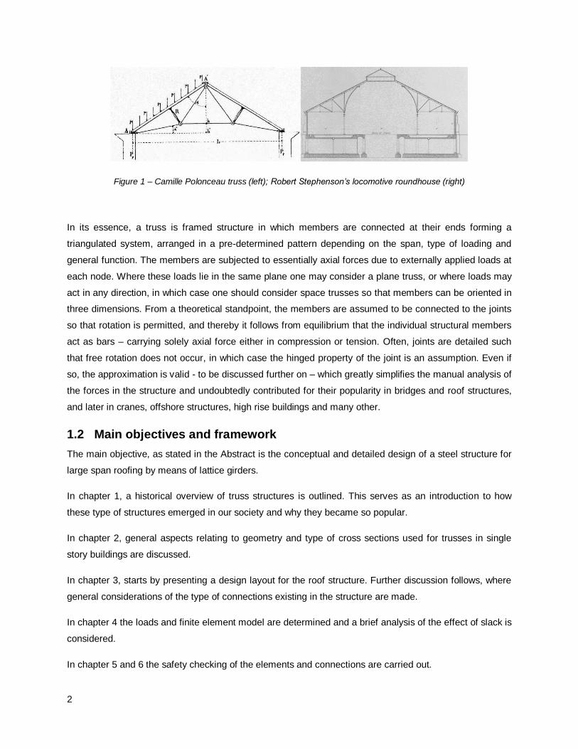
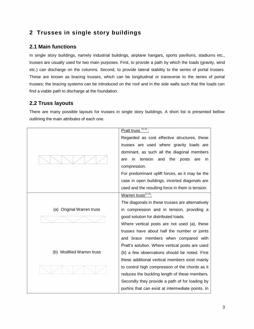


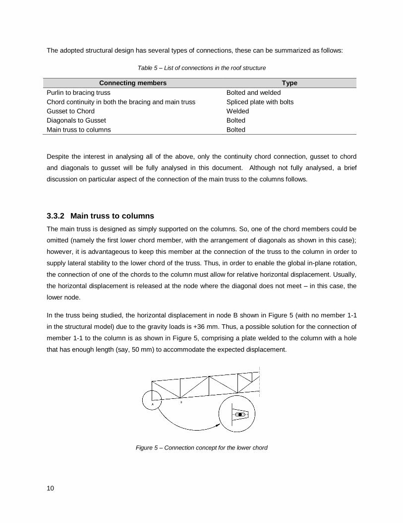


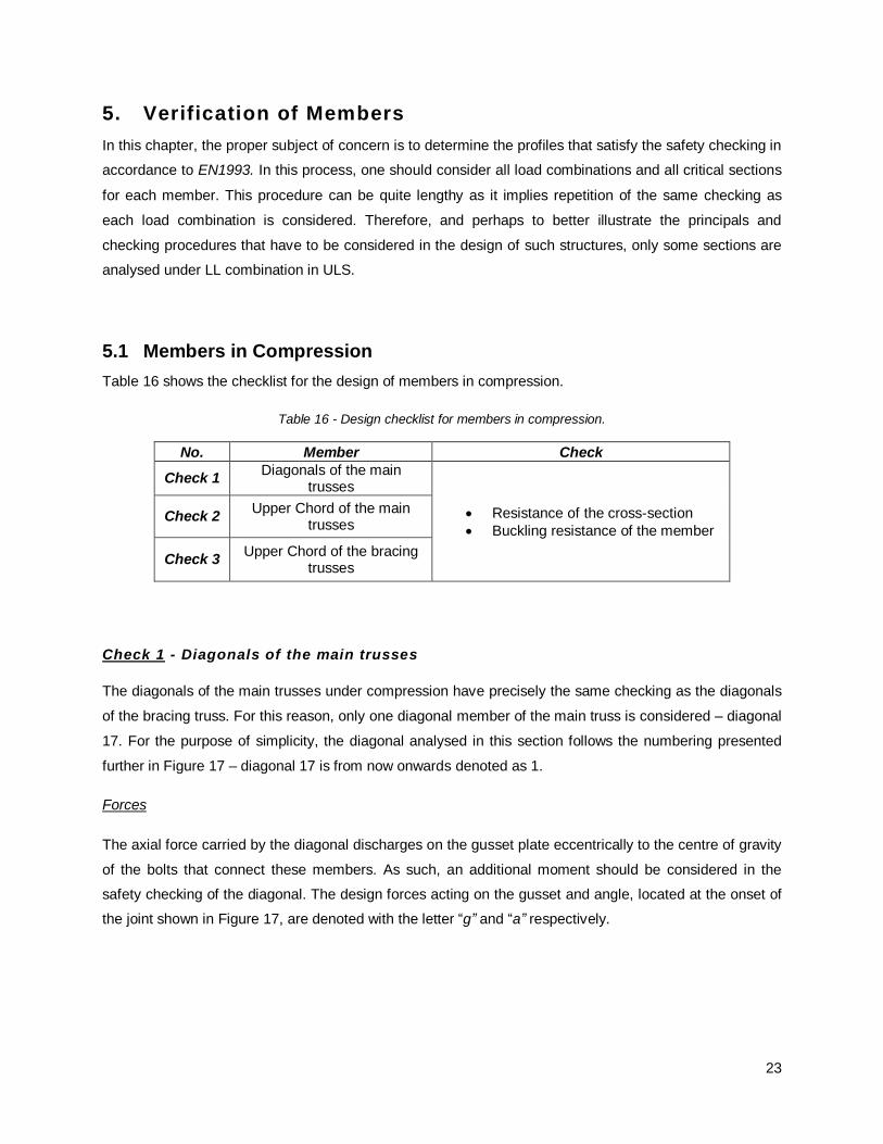


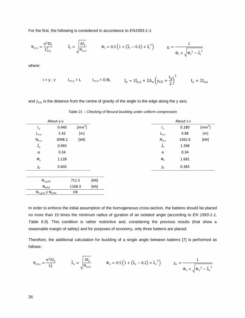

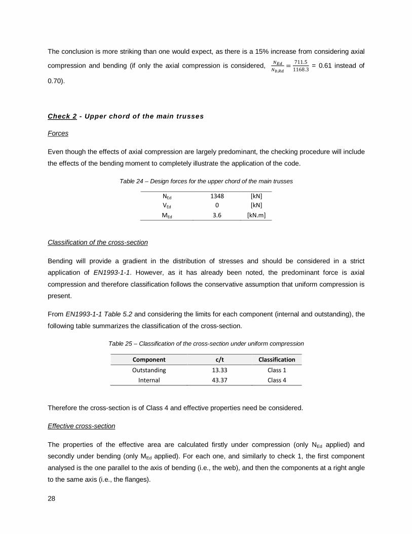


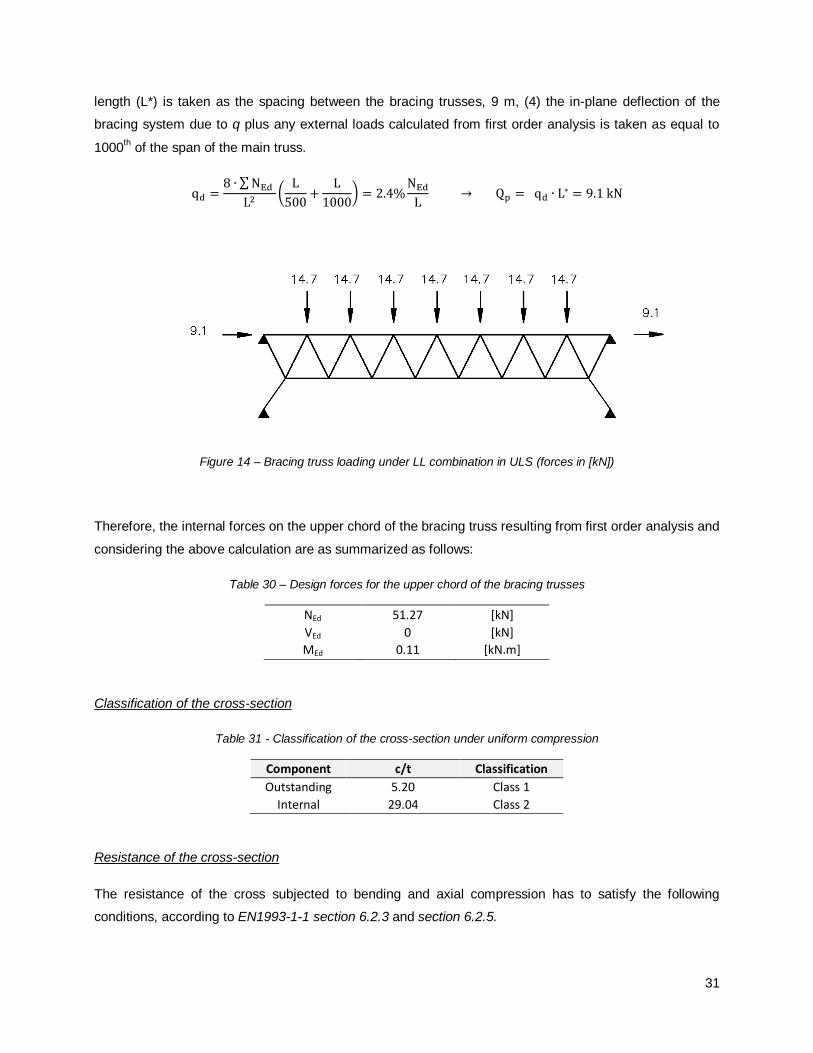


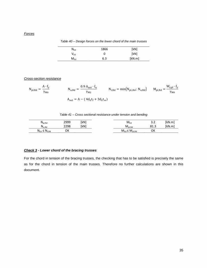


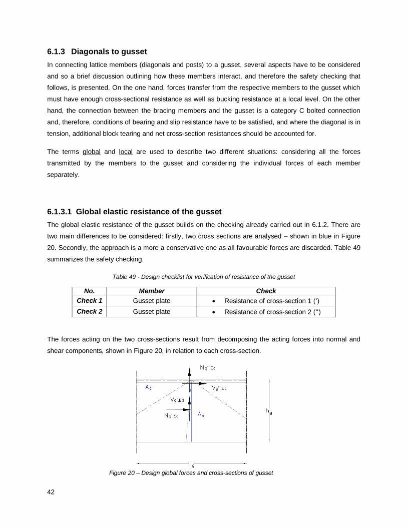


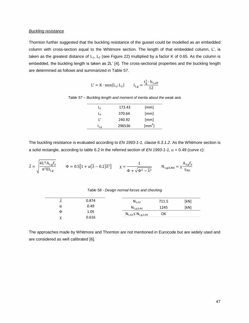


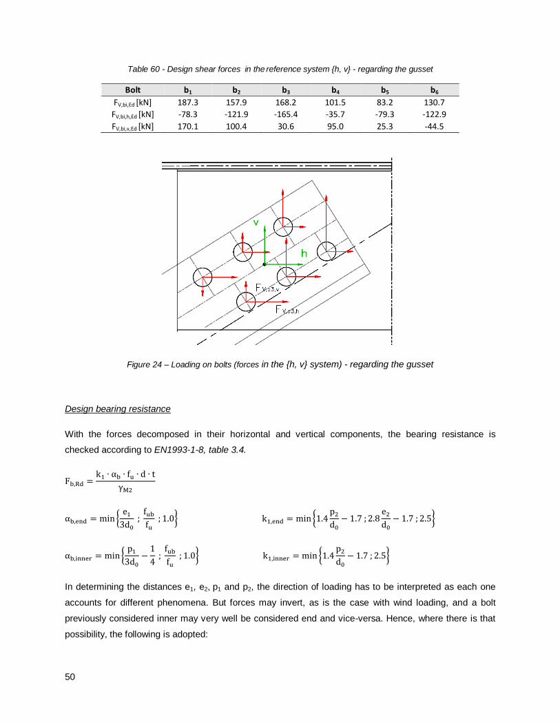

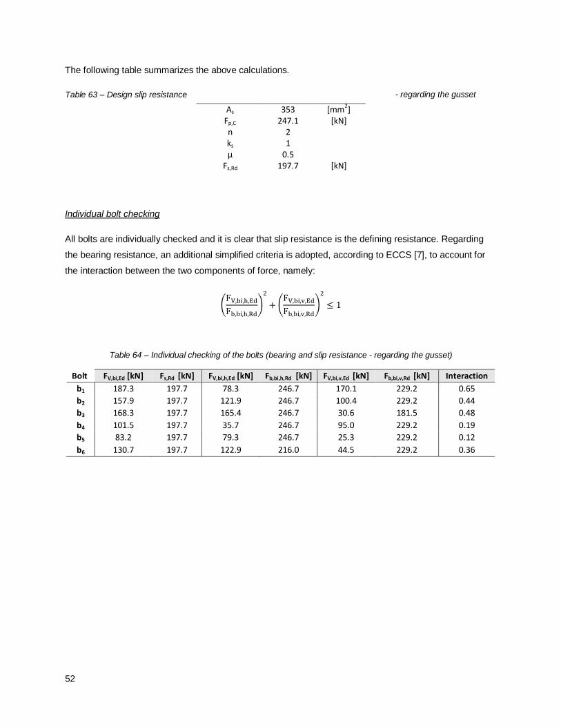


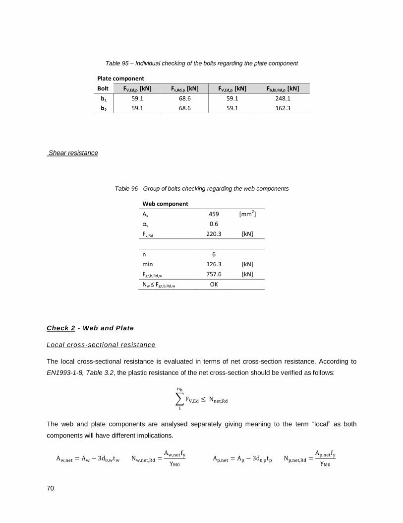


![Bolted Connections[1]](https://static.documents.pub/doc/80x56/54e7f8c84a7959704f8b46b8/bolted-connections1.jpg)


![[SATO] Bolted Flange Plate Moment Connections](https://static.documents.pub/doc/80x56/577cd67d1a28ab9e789c841c/sato-bolted-flange-plate-moment-connections.jpg)


