Design of Accelerometer Pre-regulation Circuit and Performance Analysis of the Key Components
* Hou Zhuo, Wu Yongpeng, Zhen Guoyong
National Key Lab for Electronic Measurement and Technology, Tai yuan 030051, China Key Laboratory of Instrumentation Science & Dynamic Measurement North University of China,
Taiyuan, 030051, China * Tel.: +86-13994204889, fax: +86-0351-3557289
ground trials or verifications in aircraft design and development stages. And the temperature, stress, gesture, noise, acceleration as well as other dynamic sampling plays an important role. Accurate measurements of the key dynamic parameters in favor of examining the program or providing important data reference for equipments improving. Accurate, efficient and advanced measurements can significantly improve the test efficiency and reduce
the development cycle, achieving the efficient, convenient and economic purpose. The dedicated measuring system is generally consist of data recorder, sensor array and the cable network. It works along with the aircraft and samples and records the test data real-time.
The pre-regulation circuit is mainly used to pre-regulate the dynamical parameters of vibration and striking, and provide appropriate signal for sampling and knitting system on amplitude and frequency. Generally, the demand of the key component’s performance is not strict in laboratory or in the trail
Sensors & Transducers, Vol. 154, Issue 7, July 2013, pp. 188-194
189
field that the condition is not harsh. And the common component will not have a serious effect on the result of the measurement. But the accelerometer fixed on the aircraft is used to measure the stress of engine retro firing, noise of taking off and the response of structure caused by ripple stress. So even the equipment is far away from the heat condition, the temperature of the environment exist an amount change. At the moment, the key component’s performance (as capacity or insulation resistance) of the Q-V translation circuit will change with external environment’s (as temperature) changing, and the common pre-regulation circuit can’t meet the measuring demand. The pre-regulation circuit introduced in this article is special for vibration and striking or other piezoelectric accelerometer’s dynamical parameter measurement in aircraft ground trail. The design of the circuit is based on a great deal of experiments and practices. This article also proposes a constructive advice on the analysis and selection of the key component. Comparing with the measuring method in laboratory, the design has stronger environment adaptability and wider temperature range. And the pre-regulation circuit adopts a high-order filter to filter the voltage from the Q-V translation circuit. Its attenuating slope beyond the bandwidth is up to 50 dB/oct and effectively restrains the aliasing.
2. Accelerometer Measuring System Overview Accelerometer measuring system is an important
part of aircraft measuring system. It is mainly consist of the accelerometer array, signal pre-regulation modules, analog-to-digital conversion module and knitting frame and storage module. Accelerometer could translate physical changes into electrical output with the piezoelectric effect of ceramic or crystal. When it gets mechanical stresses, Signal pre-regulation module translates charges into voltage and convert the high impedance of the sensor into a low impedance, finally regulate into a suitable signal for the A-D conversion through amplifier, filter and following circuits; Analog-to-digital conversion module and storage module translate regulated analog signal into digital signal and save them. System block is shown in Fig. 1.
Fig. 1. Accelerometer measuring system block.
3. Design of the Pre-regulating Circuit 3.1. Accelerometer Equivalent Circuit
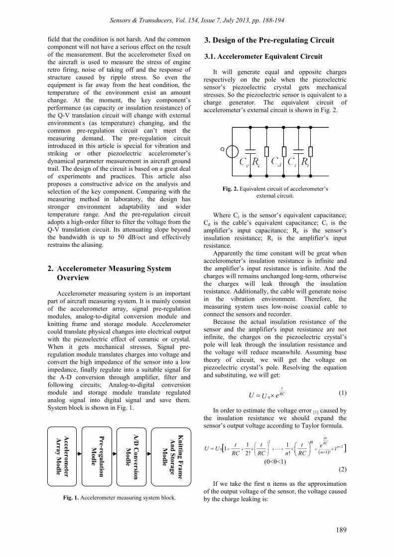
It will generate equal and opposite charges respectively on the pole when the piezoelectric sensor’s piezoelectric crystal gets mechanical stresses. So the piezoelectric sensor is equivalent to a charge generator. The equivalent circuit of accelerometer’s external circuit is shown in Fig. 2.
Fig. 2. Equivalent circuit of accelerometer’s external circuit.
Where Cc is the sensor’s equivalent capacitance; Cd is the cable’s equivalent capacitance; Ci is the amplifier’s input capacitance; Rc is the sensor’s insulation resistance; Ri is the amplifier’s input resistance.
Apparently the time constant will be great when accelerometer’s insulation resistance is infinite and the amplifier’s input resistance is infinite. And the charges will remains unchanged long-term, otherwise the charges will leak through the insulation resistance. Additionally, the cable will generate noise in the vibration environment. Therefore, the measuring system uses low-noise coaxial cable to connect the sensors and recorder.
Because the actual insulation resistance of the sensor and the amplifier's input resistance are not infinite, the charges on the piezoelectric crystal’s pole will leak through the insulation resistance and the voltage will reduce meanwhile. Assuming base theory of circuit, we will get the voltage on piezoelectric crystal’s pole. Resolving the equation and substituting, we will get:
0
t
RCU eU (1)
In order to estimate the voltage error [1] caused by the insulation resistance we should expand the sensor’s output voltage according to Taylor formula.
22
01 !
1 11
2! ![ ]
t
RCn
n
nt t t eU U tRC RC n RC
(0<θ<1) (2)
If we take the first n items as the approximation
of the output voltage of the sensor, the voltage caused by the charge leaking is:
Accelerom
eter A
rray Mod
le
Pre-regu
lation
Mod
le
A/D
Conversion
M
odle
Kn
itting Fram
e A
nd S
torage M
odle
Sensors & Transducers, Vol. 154, Issue 7, July 2013, pp. 188-194
190
( 1)
1 !
tnRC
tU e
n
(3)
Because the feedback capacitor depends on the
op-amp’s output sensitivity, it could not be increased at random [2]. We usually select the op-amp with high input resistance, low impedance cable, the sensor with high output impedance to reduce the charges leaking.
3.2. Design of the Charge–voltage Conversion Circuit
The charge-voltage conversion circuit designed
with integrated op-amp and RC network is shown in Fig. 3.
Fig. 3. Charge–voltage conversion circuit. Theoretically, due to the impact of the input offset
voltage, offset current, input bias current of the actual op-am and the feedback capacitor’s leaking current and temperature drift, the integral circuit will produce integral drift. Even if the input voltage is zero, the output voltage of the op-amp will still change in a certain direction. The changing voltage will charge the feedback capacitor until the input voltage reaches saturation. So we should select the op-amp with low offset parameters and the capacitor with high insulation resistance as the feedback capacitor. Meanwhile we should also parallel with a high-value resistor across the feedback capacitor composing a DC negative feedback to effectively restrain the integral drift and stabilize the DC operating point [3]. We could see in Fig. 3 that the op-amp is supplied with 5 VDC and the reference voltage of the op-amp's positive input is 1.25 VDC, so that the output voltage is above 0VDC, meeting the requirements of the A-D conversion chip’s input voltage.
We select the accelerometer as the measuring equipment in this article that the maximum range is 500 g, the sensitivity is 150 pC/g, the frequency response range is 0.3 to 5 kHz, and transverse sensitivity is less than 5 %. The charge from the sensor is 75000 pC when peak voltage of the amplifier’s output is 1 V. The charges from the accelerometer charge the feedback capacitor, and thus the charge are translated into voltage. We will
easily get the feedback capacitor’s value, according to the charge-voltage conversion formula. When the output voltage’s attenuation reaches 3 dB, the corresponding input frequency is in the low frequency band. If the input signal’s minimum cut-off frequency is redundant to 0.1 Hz, the feedback resistor is 10 MΩ.
Through the analysis above we could get the conclusion that the feedback capacitor C2 determines the output sensitivity of the charge amplifier and the feedback resistor depends on the cut-off frequency of the input signal.
3.3. Design of the Anti Aliasing High-order Low-pass Filter Circuit
The output voltage of Q/V convert circuit at the
same time accompanied by sensor itself noise and other high-frequency noise, these noises will go into next level regulating circuit with the effective signal. The regulating circuit with high-order low-pass filter circuit can process these signals for further. Inhibit the aliasing phenomenon in the AD sampling process effectively, restore the Changes of dynamic parameters like impact vibration in real situation extremely. The filter orders and the cut-off frequency are the key indicators of the regulating circuit [5], for measuring the parameters of the shock, vibration, etc. The accelerometer use high order filter chip (greater than or equal to eight orders) in order to obtain good quality factor, steep frequency response curve, smaller in-band flatness, besides the cutoff frequency, signal attenuation slope can be close to 50 dB/oct.
The design of cutoff frequency depends on the attenuation of the anti aliasing filter attenuation and the type of analysis and the expected square value of frequency in signal higher than the Nyquist frequency. This article take the typical example of a accelerometer that measure impact parameters, signal band-width limited in 10 kHz, using ten-order anti aliasing filter, the Nyquist frequency is about 20 kHz, designing and sampling frequency is about 100 ksps, the cutoff frequency, a quarter of the sampling rate, is 25 kHz, attenuation slope of is not less than 50 db/oct.
The anti aliasing filter below the Nyquist frequency of the sensor bandwidth range expects having a flat frequency response, but the actual test result often has amplitude and phase errors because of a slight attenuation and frequency shifting. In order to prevent this kind of potential problems, we use anti aliasing filter provide constant delay time, that is linear phase, in theory.
The application of the various types of filters behaves differently in actual: Bessel filter has linear phase function under the cut-off frequency, but poor cut-off characteristic; Butterworth filter has good cut-off characteristic, but bring in nonlinear phase, especially near the cut-off frequency. Elliptic filter can be designed to have a good cut-off characteristic
Sensors & Transducers, Vol. 154, Issue 7, July 2013, pp. 188-194
191
and until the cut-off frequency is close to linear phase, but its frequency response above the cut-off frequency may show great leakage side-lobe.
Integrated all kinds of filter characteristics, this paper finally adopt LTC1569 [7] as the filter chip, as is shown in Fig. 4.
Then
Hzor
RKKfcutoff 164,1
)/10(128 3 (4)
According to chip data about LTC1569, the 5th-
pin cut-off dividing frequency instructions, the capacitance is shorted out, the CLK is grounded through C2, the cut-off frequency is with one frequency calculation the R3 is 12 k then is
kHzHzKKK
fcutoff 7.261
)12/10(128 (5)
In the case of the technical indicators to the filter without special requirements, take cost into considerations, the amplifier and low active filter consist of resistance-capacitance network, but the actual frequency response curve is much more gentle compared with high-order filter .Note that, high-order like LTC1569, although can provide high quality filtering properties, but due to the chip filtering methods based on switch capacitance effect, its output will produce high-frequency switching noise, the noise frequency is usually set 32-64 times of the cut-off frequency. In this case, you can use such as second-order voltage controlled low-pass filter to eliminate the noise.
Fig.4. design of ten-order low-pass filter.
4. Key Components’ Performance Analysis for the Pre-regulation Circuit
4.1. Analysis of Capacitor’s Temperature
Characteristics
In finally we take a temperature experiment for the final product from -40 C to +60 Catha input is given by a charge generator, but the output get from the measuring system is different from the input seriously. Finally we analysis the Charge-Voltage conversion circuit’s key components and found the feedback capacitor’s capacity changed with the temperature increasing or decreasing.
The changes of the capacitor’s capacity mainly depend on the dielectric material’s influence by temperature. Further, the structure and procession of the capacitor will also affect the temperature characteristic. The temperature coefficient of the common capacitor is shown in the Table 1.
In this article, we experiment with round ceramic capacitors, ceramic chip capacitors, monolithic capacitors and polystyrene capacitor from -40 C to +60 C. Their capacitances were listed as below: round ceramic capacitor 0.105 μF; ceramic chip capacitors 0.115 μF; monolithic capacitor 0.072 μF; polystyrene capacitor 0.098 μF at +25 C. We divided the whole experiment temperature into 20 aliquots and each temperature keeps 15 minutes to ensure that the permittivity reaches a stable value at the temperature. Then read the capacitance with a precise multimeter. The capacitances are listed in Table 2 and the experimental result is shown in Fig. 5.
Polystyrene capacitors’ dielectric is polystyrene organic film. Its mainly polarization form is electronic displacement polarization, its dielectric constant ε is generally small (about 1.8 to 2.6) and it is independent of the frequency. Its capacitance basically keeps stable with the temperature changing.
The dielectric of the round ceramic capacitors, ceramic chip capacitors and monolithic capacitors belongs to Class II ceramic. When temperature is low, the interaction between molecules is strong and the dipole’s orientation doesn’t rely on the external electric field. With the temperature increasing, the thermal energy of the molecule increase and the binding force between the molecules weakened. The molecules along the external electric field’s orientation, ε also increases. When temperature is high, the binding force between the molecules is
Sensors & Transducers, Vol. 154, Issue 7, July 2013, pp. 188-194
192
greatly decreased, the thermal energy of the dipoles can be greatly increased. And when it reaches a certain temperature, the thermal energy can in turn destroy the effect of the external electric field to the polar molecules, resulting the decline of ε [4]. Therefore, the capacity will appear a maximum value with temperature changing.
Table 2. The Value of Capacitors Reader in Temperature Experiment.
4.2. Affection of Insulation Resistance to the Conversion Circuit’s Output
When the DC voltage applied to the capacitor and
generated leaking current, the ratio of voltage to leaking current is defined as the insulation resistance. Assuming that the charge-voltage conversion circuit
gets a constant acceleration, the amount of charge will be constant. And the charge will be released through the feedback capacitance’s insulation resistance. If the capacitors’ insulation resistance is small, the charge will be rapidly released. It means that the measurement system can not accurately respond to the low frequency of the acceleration. The insulation resistances of different capacitors vary; the insulation resistance will also be different with temperature changed.
The relation of the insulation resistance and the temperature meet the following equation:
2 1( )
2 1t tR R e (6)
or
2 2 1lg lg 1 ( )R R t t , (7)
where R1 is the insulation resistance at temperature t1; R2 is the insulation resistance at temperature t2; β is the constant, depending on the dielectric.
4.3. Summary
As shown above, the temperature characteristics and insulation resistance of the capacitor will have a direct impact on the quality of regulation. For example, if we select monolithic (0.1 μF) capacitors as the feedback capacitor, the error caused by temperature will up to 800 %. While the error of the polystyrene capacitors only up to 3 %. Therefore, the selection of the feedback capacitor will be critical. It is necessary to possess perfect temperature characteristics, but also possess a large insulation resistance at the same time. It is easily found that the temperature characteristic and the insulation resistance of polystyrene capacitors are ideal. Engineering practices proved that selecting polystyrene capacitor as the feedback capacitor will greatly reduce the error caused by the changes of the environment.
Finally we will validate the accelerometer with regulating circuit when the measuring system is completed firstly, to verify the correctness of the charge/voltage conversion circuit. In the experiment, the accelerometer is fixed on the vibration table and samples the accelerometer’s output in the sine sweeping mode. Sampled data is shown in Fig. 6.The maximum of the controlling spectra is ±30 g, the frequency range is 200±50 Hz. As shown in
Sensors & Transducers, Vol. 154, Issue 7, July 2013, pp. 188-194
193
Fig. 6, the accelerometers’ vibrating frequency is about 160 Hz and the actual controlling spectrum is about ± 30 g. The measuring system after Linear fitting demarcated actually reflects the experimental procession by scaling transformation.
5.2. Frequency Response of Accelerometer Regulating Circuit
According to the typical example of a
accelerometer that measure impact parameters in this article, do the frequency sweep test on the basis of the sensor band-width range and the cut-off frequency of high-order low-pass filter circuit, to examine the frequency response of the accelerometer's regulating circuit.
From the Fig. 7, the channel cut-off frequency is about 26773 Hz, the attenuation is - 42.88 dB in the two octaves of signal band-width 40 kHz. By analyzing the curve trend. The attenuation is over 50 dB/oct, two octave of the cut-off frequency just about 50 dB/oct.
Fig. 6. The sine weeping curve of accelerometer.
5.3. Engineering Applications
The measuring system, accelerometer array and
the cable network introduced in this article participate in a large aircraft ground trial after demarcated and validated. The acceleration data of a channel sampled in the trial is shown in Fig. 8.
Fig. 7. Frequency response Bode Plot.
Fig. 8. The vibration curve of a channel in a trail.
Sensors & Transducers, Vol. 154, Issue 7, July 2013, pp. 188-194
194
6. Conclusion
We select the accelerometer as the reaching object in this article and take a discussion about the sensor’s equivalent circuit and the design of pre-regulating circuit. The article mainly analysis and research the performance of the pre-regulating circuit’s component-feedback capacitor and related parameters. The pre-regulation circuit introduced in this article haven successfully participated in many ground ejection trial. The effect is ideal, performance is stable and reliable, perfectly adapt the environment. References [1]. Xie, J., Design of a new charge amplifier, Thesis of Xi
An Polytechnic University, 2008.
[2]. Xu, S. Q. and X. Y. Yang, Vibration measuring system design and application of the double integral charge amplifier, Laboratory Research and Exploration, Vol. 4, 1994, pp. 75-82.
[3]. Jia, X. Z., Design Of Data Measuring System Used In Missile Ejecting Test, Thesis of North University of China, 2010.
[4]. Radio Materials and Devices Department of Tianjin University, Capacitor, Technical Standards Press, 1981, pp. 6-9.
[5]. Tong, S. B., Fundaments of Analog Electronics, Higher Education Press, Beijing, China, 1980.
[6]. Lv, J. F, Sensor interface and Detection circuit, National Defence Industry Press, 2009.
[7]. The datasheet of LTC1569-7 Linear Phase, DC Accurate, Tunable, 10th Order Lowpass Filter, Linear Technology.
[8]. Chen, J. and Huang, H, Sensor and Detection Technology, Higher Education Press, 2002.