AbstractPurpose The biopsy procedure is an important phase in breast cancer diagnosis. Accurate breast imaging and precise needleplacement are crucial in lesion targeting. This paper presents an end-effector (EE) for robotic 3D ultrasound (US) breastacquisitions and US-guided breast biopsies. The EE mechanically guides the needle to a specified target within the US plane.The needle is controlled in all degrees of freedom (DOFs) except for the direction of insertion, which is controlled by theradiologist. It determines the correct needle depth and stops the needle accordingly.Method In the envisioned procedure, a robotic arm performs localization of the breast, 3D US volume acquisition and recon-struction, target identification and needle guidance. Therefore, the EE is equipped with a stereo camera setup, a picobeamer,US probe holder, a three-DOF needle guide and a needle stop. The designwas realized by prototyping techniques. Experimentswere performed to determine needle placement accuracy in-air. The EE was placed on a seven-DOF robotic manipulator todetermine the biopsy accuracy on a cuboid phantom.Results Needle placement accuracy was 0.3±1.5 mm in and 0.1±0.36 mm out of the US plane. Needle depth was regulatedwith an accuracy of 100 µm (maximum error 0.89 mm). The maximum holding force of the stop was approximately 6 N.The system reached a Euclidean distance error of 3.21 mm between the needle tip and the target and a normal distance of3.03 mm between the needle trajectory and the target.Conclusion An all in one solution was presented which, attached to a robotic arm, assists the radiologist in breast cancerimaging and biopsy. It has a high needle placement accuracy, yet the radiologist is in control like in the conventional procedure.
Breast cancer is the most prevalent cancer in women world-wide. In 2018 alone, nearly 2.1 million new cases werediagnosed [1]. It is essential for these women that the diag-nosis is confirmed in an early stage of the disease as early
Electronic supplementary material The online version of this article(https://doi.org/10.1007/s11548-020-02122-1) containssupplementary material, which is available to authorized users.
1 Robotics and Mechatronics, University of Twente, Enschede,The Netherlands
2 Ziekenhuisgroep Twente, Almelo, The Netherlands
3 Bio-mechatronics and Energy-Efficient Robotics Group,ITMO University, St. Petersburg, Russian Federation
detection is known to reduce mortality rates in breast cancer[2].
Several methods are used to detect lesions including self-examination through palpation and imaging modalities suchas mammography, ultrasound (US) scans and magnetic res-onance imaging (MRI) scans. Mammography is the mostcommon imaging modality in clinical practice. If a lesionis detected, a tissue sample is required to confirm malig-nancy. This tissue sample is acquired using a biopsy needle,after which the sample is sent to the pathologist. Mostly,the biopsy procedure is performed under US guidance. Theradiologist navigates the needle based on US feedback. Dis-advantages of this procedure include difficulties in extractingcells from the lesion due to its small size, or poor sen-sitivity due to difficulties in visualizing tumors against abackground of dense fibroglandular tissue [3]. Also, needleinsertion is hampered by tissue boundaries and lesion dis-placement because of forces exerted during needle insertion.
682 International Journal of Computer Assisted Radiology and Surgery (2020) 15:681–690
The biopsy is repeated if the lesion is not hit at the previousattempt. Consequently, radiologists should be experiencedto be successful. However, clinicians who frequently use thistechnique often suffer from fatigue and work-related mus-culoskeletal discomfort [4]. These work-related issues willbecome more frequent since the number of breast biopsiesis increasing due to broader access to population screeningsfor breast cancer.
Robotics can play a major role in these challenges; robotscan more accurately, precisely and stably manipulate toolsthan humans. Moreover, robots do not experience fatigueand consequently the time per patient can be brought down[5]. Furthermore, a robotically steered US probe can produceaccurate 3D US volume reconstruction. The US probe posi-tion is acquired with high precision utilizing the sensors inthe robot, and uniformly spaced slices can be produced withcoordinatedmovements. The accuracy of a biopsy benefits ofimage fusion of preoperative images is acquired by, e.g.,MRIwith intra-operative data like US [6]. If the robot “knows” itsrelative position to the breast and is able to generate a precise3D US volume, this can ease registration. Because of theseadvantages, the number of false negatives during a robot-assisted US-guided biopsy is potentially reduced comparedto the regular procedure and patient discomfort and cost canbe brought down.
Thus, robotic assistance during US-guided breast biop-sies is beneficial by providing a stable hand and real-timeimage feedback. The previous studies focused mainly on thedesign of mechanisms to assist the radiologist to more accu-rately perform minimally invasive procedures. Determiningthe position of the target relative to the biopsy device is animportant step in a robot-assisted biopsy. This can be per-formed by registering preoperative images with the robot andthe patient. Several studies utilized optical tracking to relatepreoperative images to the robot [7–10]. Nelson et al. [11]used a laser scanner to register a preoperative 3D US acqui-sition to the current position of the breast. The advantageof using just preoperative imaging is that the trajectory plan-ning is not influenced or restricted by, e.g., US probe position.However, the procedure lacks real-time information to cor-rect for deformations. Several studies utilized real-time USguidance aswell. The position of theUSprobewith respect tothe needle can be tracked optically, calculated based on jointsensors of the robot(s) holding the probe and/or the needle,or measured if the position of the US probe is static withrespect to the needle base frame [7, 12–15].
Additionally, there are several approaches to needle inser-tion underUSguidance. Liang et al. [14] presented a six-DOFrobot holding a 3D US probe with the needle fixed to theprobe. Mallapragada et al. [16, 17] presented a needle whichhad a fixed insertion orientation relative to the probe, butmanipulated the tissue. Other studies presented setups inwhich the needle/needle guide has some degrees of freedom
in the image plane of the US probe [13, 15, 18–21]. In somecases, the needle had DOFs out of the US plane as well orthe US probe had degrees of freedom also [22–24]. If theneedle moves independently of the US probe, there are moreoptions for targeting lesions. However, if the needle movesout of the US plane, the US feedback is less accurate.
The above-mentioned studies show that the introductionof robotics to the biopsy workflow is advantageous for theaccuracy of the procedure. However, to truly benefit fromdevelopments in the area of robotics such as the medicallycertified robotic arms, there is the need for an all in onesolution. If one tool enables a robotic arm to autonomouslyperform all steps of the breast biopsy, the system becomesless complex and expensive, and inter-system calibrationerrors are ruled out. This will lead to a higher accuracy andfaster acceptance in the medical world [25]. The aim of thispaper is to present the design of an end-effector (EE) forutilization in a robot-assisted breast biopsy. The EE con-tains an actuated needle guide which directs the needle to aspecified target within the US plane. The needle insertion isperformed by the radiologist, which assures a human is stillin control during the invasive step. The EE tracks the inser-tion and mechanically stops the needle at the specified depth.Utilizing the proposed system, MR-detected lesions may betargeted by a US-guided biopsy based on a registration step,which is less invasive than an MR-guided biopsy. Further-more, biopsies can be consistently and reliably performedindependently of the clinical background of the person per-forming the biopsy.
The paper is structured as follows: in “Design analysis”section, an analysis of the design constraints is presented.“End-effector” section presents the proposed and imple-mented design. “Experimental validation” section presentsthe measurements performed to characterize the system, andin “Discussion” section, the results are discussed. The paperconcludes with “Conclusion and recommendations” section.
Design analysis
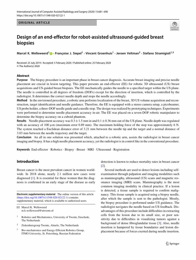
The envisioned robot-assisted US-guided biopsy procedureconsists of several phases (Fig. 1). First, a breast MRI isacquired in prone position. Then, the patient is positioned inprone position over the robot. This reduces motion artifactsand simplifies registration with the preoperative MRI scan.Multi-modality markers, visible in MRI, US and on camera,were attached to the breast.
The robot determines its position relative to the breast bymoving around the breast and detecting the markers withcameras attached to the end-effector (Fig. 1a). The MRI dataare then registered with the optical data. The markers’ rel-ative positions and projections of a projector can be used
123
International Journal of Computer Assisted Radiology and Surgery (2020) 15:681–690 683
US Probe(side view)
US Probe(front view)
a b c
R=90mmBreast
50mm30mm
US probe
d
TableBreast
Robotic arm
needle guide
Fig. 1 Robot-assisted biopsy workflow. a The robot scans the breastwith cameras and registers the breast surface by projecting light or rec-ognizing markers. b The robot scans the breast with a 2D US probe for3D US volume reconstruction. c The robot visualizes the target in the
US image. d The robot targets the lesion by aiming the needle guideto the correct location. In situations b and c, an angle of 45° of theprobe relative to the flange is beneficial to navigate closely to the chestwall/patient table
for possible deformations compared to the preoperative MRIdata.
Subsequently, the robot scans the breast surface with a 2Dlinear probe to acquire 3DUS data. The volume is built up bystreaming the 2D images with their corresponding positiondata to a reconstruction algorithm. It is important to navigateclosely to the bed to optimize the scanning area. Therefore,the probe should be tilted with respect to the robot flange (seeFig. 1b).
The needle tip should be within the field of view (FOV) ofthe US transducer during insertion. This allows for real-timeimage feedback of both the needle tip and tissue deforma-tions. The needle tip should be aligned with the lesion in thebreast and approximately parallelwith the transducer array ofthe US probe for needle visibility. Therefore, the needle willbe inserted approximately 3–5 cm from the edge of the trans-ducer. Furthermore, the needle is preferably inserted parallelto the chest wall because this reduces the risk for a pneu-mothorax. Due to these requirements, the anticipated pose ofthe probe during a biopsy is as shown in Fig. 1c.
If the US probe is correctly placed on the breast surface,the lesion will be a point in the 2D US image. The orienta-tion and position of the needle guide are determined by thetarget and the insertion position. Therefore, a three degreeof freedom (3DOF) articulated needle guide suffices to cor-rectly aim the needle toward the lesion in the US imageplane (Fig. 1d). The method to determine the joint angleson the basis of the needle guide’s position and orientation isdescribed in [26]. The desired workspace of the manipula-tor is defined by the needle insertion rules and the diameterof the female breast, which is approximated to a maximumof 18 cm [27]. The needle guide should successfully targetlesions with a size ranging from 4 to 10 mm. This includeslesions that are difficult to detect on US images but can berecognized on MRI [28].
The needle will be inserted in the breast through the nee-dle guide, which limits the movement of the needle to thedirection of insertion. The needle guide should stop and holdthe needle at the desired depth, regardless of needle lengthand diameter. The brake should exert forces higher than theinsertion forces to stop the needle. These forces will havea range of 0–3.5 N [29, 30]. Preferably, the mechanism issubstituted or sterilized easily after usage.
End-effector
Design
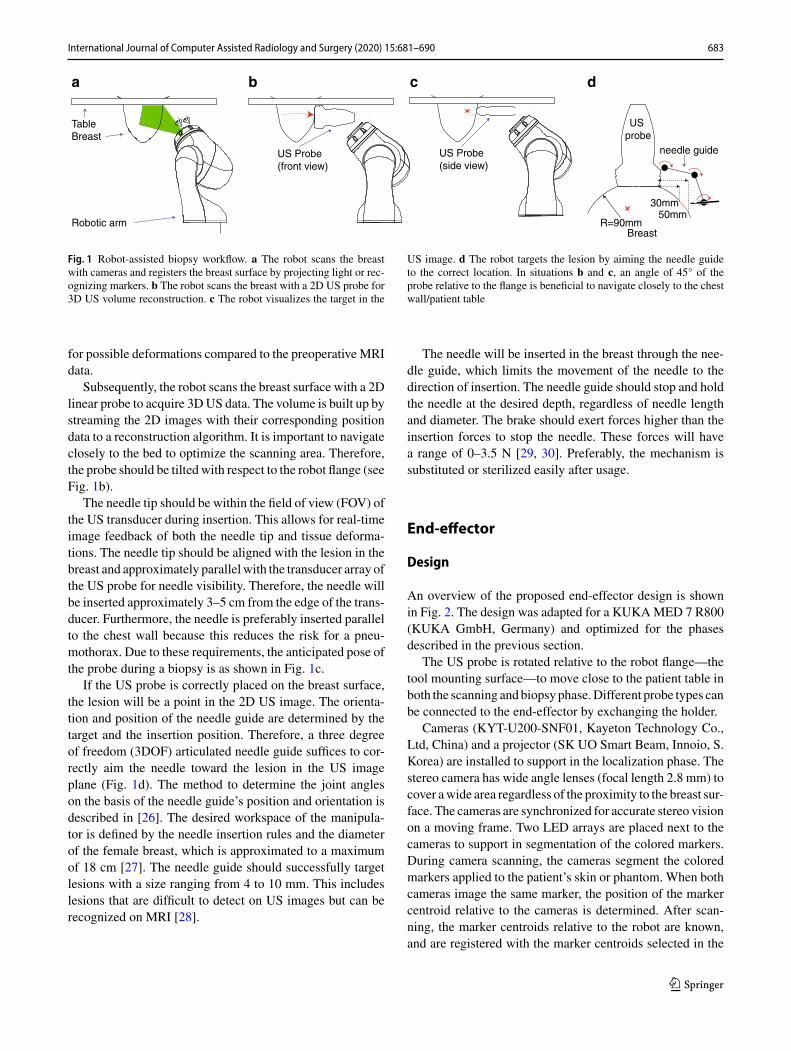
An overview of the proposed end-effector design is shownin Fig. 2. The design was adapted for a KUKAMED 7 R800(KUKA GmbH, Germany) and optimized for the phasesdescribed in the previous section.
The US probe is rotated relative to the robot flange—thetool mounting surface—to move close to the patient table inboth the scanning andbiopsyphase.Different probe types canbe connected to the end-effector by exchanging the holder.
Cameras (KYT-U200-SNF01, Kayeton Technology Co.,Ltd, China) and a projector (SK UO Smart Beam, Innoio, S.Korea) are installed to support in the localization phase. Thestereo camera has wide angle lenses (focal length 2.8 mm) tocover awide area regardless of the proximity to the breast sur-face. The cameras are synchronized for accurate stereo visionon a moving frame. Two LED arrays are placed next to thecameras to support in segmentation of the colored markers.During camera scanning, the cameras segment the coloredmarkers applied to the patient’s skin or phantom. When bothcameras image the same marker, the position of the markercentroid relative to the cameras is determined. After scan-ning, the marker centroids relative to the robot are known,and are registered with the marker centroids selected in the
123
684 International Journal of Computer Assisted Radiology and Surgery (2020) 15:681–690
Needle guide
Stereo cameras
Projector
LED array
US probe
Flange connection
z
xy z
xyz
xy
Fig. 2 Isometric projections of the end-effector design. The US probe tip is rotated 45° w.r.t. the robot flange around both x- and y-axes. Furtherindicated are the needle guide, stereo cameras, projector, LED array and the US probe
0 50 100
0
50
100
-50
-100
-50x (mm)
z (m
m) Link 1
Link 2
Joint 1
Joint 2
Joint 3
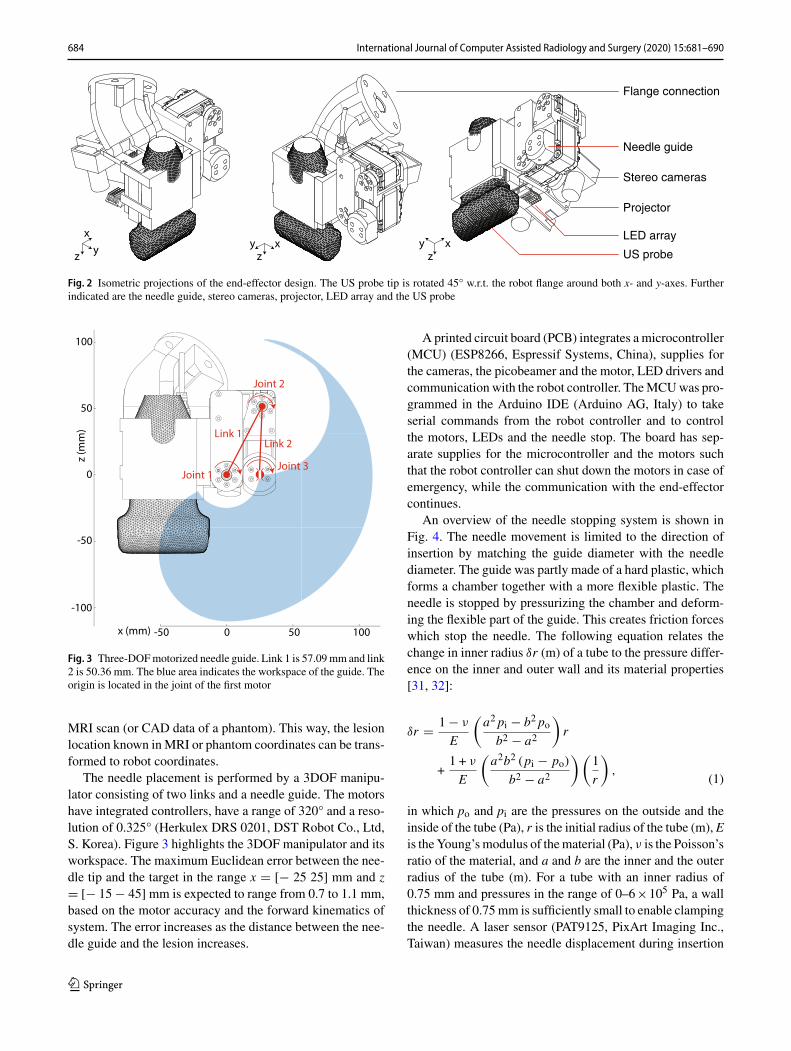
Fig. 3 Three-DOFmotorized needle guide. Link 1 is 57.09mm and link2 is 50.36 mm. The blue area indicates the workspace of the guide. Theorigin is located in the joint of the first motor
MRI scan (or CAD data of a phantom). This way, the lesionlocation known inMRI or phantom coordinates can be trans-formed to robot coordinates.
The needle placement is performed by a 3DOF manipu-lator consisting of two links and a needle guide. The motorshave integrated controllers, have a range of 320° and a reso-lution of 0.325° (Herkulex DRS 0201, DST Robot Co., Ltd,S. Korea). Figure 3 highlights the 3DOF manipulator and itsworkspace. The maximum Euclidean error between the nee-dle tip and the target in the range x � [− 25 25] mm and z� [− 15 − 45] mm is expected to range from 0.7 to 1.1 mm,based on the motor accuracy and the forward kinematics ofsystem. The error increases as the distance between the nee-dle guide and the lesion increases.
A printed circuit board (PCB) integrates a microcontroller(MCU) (ESP8266, Espressif Systems, China), supplies forthe cameras, the picobeamer and the motor, LED drivers andcommunication with the robot controller. TheMCUwas pro-grammed in the Arduino IDE (Arduino AG, Italy) to takeserial commands from the robot controller and to controlthe motors, LEDs and the needle stop. The board has sep-arate supplies for the microcontroller and the motors suchthat the robot controller can shut down the motors in case ofemergency, while the communication with the end-effectorcontinues.
An overview of the needle stopping system is shown inFig. 4. The needle movement is limited to the direction ofinsertion by matching the guide diameter with the needlediameter. The guide was partly made of a hard plastic, whichforms a chamber together with a more flexible plastic. Theneedle is stopped by pressurizing the chamber and deform-ing the flexible part of the guide. This creates friction forceswhich stop the needle. The following equation relates thechange in inner radius δr (m) of a tube to the pressure differ-ence on the inner and outer wall and its material properties[31, 32]:
(1)
δr � 1 − ν
E
(a2 pi − b2 pob2 − a2
)r
+1 + ν
E
(a2b2 (pi − po)
b2 − a2
)(1
r
),
in which po and pi are the pressures on the outside and theinside of the tube (Pa), r is the initial radius of the tube (m), Eis theYoung’smodulus of thematerial (Pa), ν is the Poisson’sratio of the material, and a and b are the inner and the outerradius of the tube (m). For a tube with an inner radius of0.75 mm and pressures in the range of 0–6×10⁵ Pa, a wallthickness of 0.75mm is sufficiently small to enable clampingthe needle. A laser sensor (PAT9125, PixArt Imaging Inc.,Taiwan) measures the needle displacement during insertion
123
International Journal of Computer Assisted Radiology and Surgery (2020) 15:681–690 685
Laser sensor
SolenoidValve
Needle
Needle Guide
µController
Pressure
Flexible Hard plastic
a b c
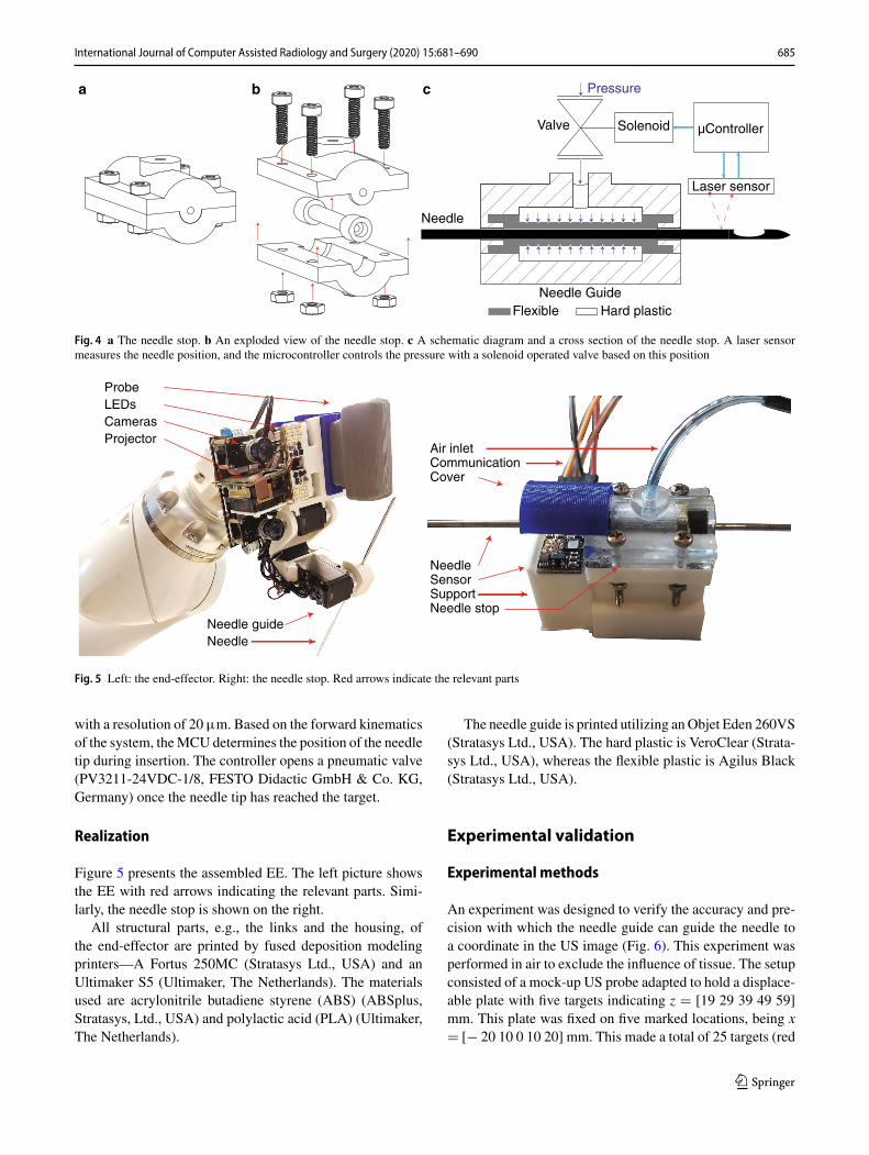
Fig. 4 a The needle stop. b An exploded view of the needle stop. c A schematic diagram and a cross section of the needle stop. A laser sensormeasures the needle position, and the microcontroller controls the pressure with a solenoid operated valve based on this position
Needle guideNeedle
Cameras
ProbeLEDs
Projector
SensorSupport
Air inlet
CoverCommunication
Needle stop
Needle
Fig. 5 Left: the end-effector. Right: the needle stop. Red arrows indicate the relevant parts
with a resolution of 20µm. Based on the forward kinematicsof the system, theMCU determines the position of the needletip during insertion. The controller opens a pneumatic valve(PV3211-24VDC-1/8, FESTO Didactic GmbH & Co. KG,Germany) once the needle tip has reached the target.
Realization
Figure 5 presents the assembled EE. The left picture showsthe EE with red arrows indicating the relevant parts. Simi-larly, the needle stop is shown on the right.
All structural parts, e.g., the links and the housing, ofthe end-effector are printed by fused deposition modelingprinters—A Fortus 250MC (Stratasys Ltd., USA) and anUltimaker S5 (Ultimaker, The Netherlands). The materialsused are acrylonitrile butadiene styrene (ABS) (ABSplus,Stratasys, Ltd., USA) and polylactic acid (PLA) (Ultimaker,The Netherlands).
The needle guide is printed utilizing anObjet Eden 260VS(Stratasys Ltd., USA). The hard plastic is VeroClear (Strata-sys Ltd., USA), whereas the flexible plastic is Agilus Black(Stratasys Ltd., USA).
Experimental validation
Experimental methods
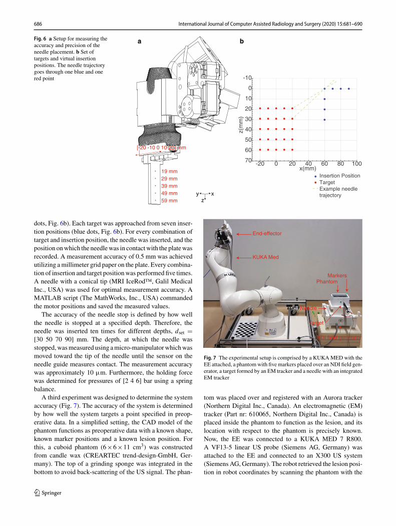
An experiment was designed to verify the accuracy and pre-cision with which the needle guide can guide the needle toa coordinate in the US image (Fig. 6). This experiment wasperformed in air to exclude the influence of tissue. The setupconsisted of a mock-up US probe adapted to hold a displace-able plate with five targets indicating z � [19 29 39 49 59]mm. This plate was fixed on five marked locations, being x� [− 20 10 0 10 20] mm. This made a total of 25 targets (red
123
686 International Journal of Computer Assisted Radiology and Surgery (2020) 15:681–690
Fig. 6 a Setup for measuring theaccuracy and precision of theneedle placement. b Set oftargets and virtual insertionpositions. The needle trajectorygoes through one blue and onered point
-20 0 20 40 60 80 100x(mm)
-10
0
10
20
30
40
50
60
70
z(m
m)
TargetInsertion Position
ba
zxy
[-20 -10 0 10 20] mm
19 mm29 mm39 mm49 mm59 mm
Example needletrajectory
dots, Fig. 6b). Each target was approached from seven inser-tion positions (blue dots, Fig. 6b). For every combination oftarget and insertion position, the needle was inserted, and theposition onwhich the needlewas in contactwith the platewasrecorded. A measurement accuracy of 0.5 mm was achievedutilizing amillimeter grid paper on the plate. Every combina-tion of insertion and target positionwas performed five times.A needle with a conical tip (MRI IceRod™, Galil MedicalInc., USA) was used for optimal measurement accuracy. AMATLAB script (The MathWorks, Inc., USA) commandedthe motor positions and saved the measured values.
The accuracy of the needle stop is defined by how wellthe needle is stopped at a specified depth. Therefore, theneedle was inserted ten times for different depths, dset �[30 50 70 90] mm. The depth, at which the needle wasstopped,wasmeasured using amicro-manipulatorwhichwasmoved toward the tip of the needle until the sensor on theneedle guide measures contact. The measurement accuracywas approximately 10 µm. Furthermore, the holding forcewas determined for pressures of [2 4 6] bar using a springbalance.
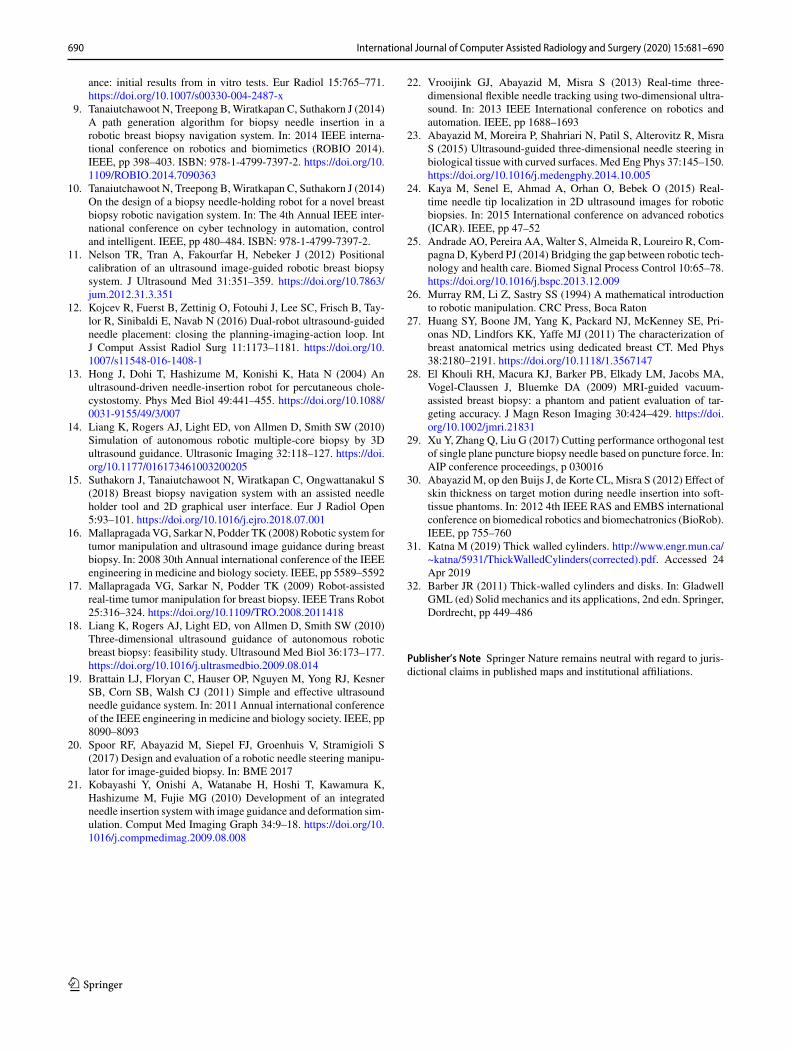
A third experiment was designed to determine the systemaccuracy (Fig. 7). The accuracy of the system is determinedby how well the system targets a point specified in preop-erative data. In a simplified setting, the CAD model of thephantom functions as preoperative data with a known shape,known marker positions and a known lesion position. Forthis, a cuboid phantom (6×6×11 cm3) was constructedfrom candle wax (CREARTEC trend-design-GmbH, Ger-many). The top of a grinding sponge was integrated in thebottom to avoid back-scattering of the US signal. The phan-
End-effector
KUKA Med
NDI field generator
PhantomMarkers
Target
Needle
Fig. 7 The experimental setup is comprised by a KUKAMED with theEE attached, a phantomwith five markers placed over an NDI field gen-erator, a target formed by an EM tracker and a needle with an integratedEM tracker
tom was placed over and registered with an Aurora tracker(Northern Digital Inc., Canada). An electromagnetic (EM)tracker (Part nr: 610065, Northern Digital Inc., Canada) isplaced inside the phantom to function as the lesion, and itslocation with respect to the phantom is precisely known.Now, the EE was connected to a KUKA MED 7 R800.A VF13-5 linear US probe (Siemens AG, Germany) wasattached to the EE and connected to an X300 US system(Siemens AG, Germany). The robot retrieved the lesion posi-tion in robot coordinates by scanning the phantom with the
123
International Journal of Computer Assisted Radiology and Surgery (2020) 15:681–690 687
60
40
20
0
-40
-20
-40
z(m
m)
-60
-80
-20 0
x(mm)
20 40 -20y(mm)
60 080 20
25
21
5
1
y(mm)
z(m
m)
57
58
59
60
615 0 -5
y(mm)
10
20
30
40
50
60
z(m
m)
-20 -10 0 10 20
x(mm)
10
20
30
40
50
60
z(m
m)
db ca
25
21
5
1
-0.5 0 0.5
Fig. 8 a Themeasured points plotted with the end-effector. b, c Themeasured points plotted in the xz- and the yz-planes, respectively. d The positionwhich was targeted the least precise
cameras, determining the marker positions with respect tothe robot and then registering the phantom with the robot-space. After registration, the robot moves to the phantom toperform the biopsy procedure. A custom biopsy needle wasproduced utilizing a metal tube with an outer diameter of2 mm and an inner diameter of 1.6 mm and equipped withan EM tracker (Part nr: 610059). The needle is inserted tothe specified position, and the Euclidean distance betweenthe two sensors is recorded to determine the accuracy. Theprocedure is performed in supine position because the bedinterferes with the signal of the Aurora system. The proce-dure was performed five times each for targets at a depth of32.5 mm and 50 mm.
Results
Theneedle guidance experimentwas performedfive times, ofwhich the first dataset was used to determine the linear trans-formation between the measurement results and the initiallytargeted positions. This transformation is applied to the restof the data, and Fig. 8 shows the results. The red dots showthe mean position for every target, while blue ellipses indi-cate the standard deviation in z- and y-directions. The meanerror in y-direction and z-direction was 0.1±0.36 mm and0.3±1.5 mm, respectively. Target 25 was targeted the leastprecise, with a standard deviation of 0.48 mm and 1.76 mmin y- and z-directions, respectively. Furthermore, target 5 hadthe largest standard deviation in z-direction, being 3.0 mm.
Table 1 Top: the set and measured needle depths. Bottom: the appliedpressure and the corresponding holding force
Set (mm) 30 50 70 90
Measured avg. (mm) 30.18 50.00 70.02 90.20
Min (mm) 29.75 49.82 69.89 90.05
Max (mm) 30.89 50.26 70.18 90.35
Pressure (bar) 2 4 6
Hold force (N) 3.5 5 6
Table 1 presents the results of the needle clamp exper-iment. During a calibration step, the bias of the micro-manipulator relative to the needle guide (1.77 mm) wasremoved, and the resolution of the sensor was adjusted to19.67 µm by means of a linear fit. The accuracy in the testedrangewas 0.100mm (maximum error 0.89mm). The holdingforce was determined to be 3.5–6 N.
Table 2 presents the results of the phantom experiment.The Euclidean distance, dEuc, between the needle tip and thetarget is 3.21 mm on average. The normal distance, dnorm,describes the shortest distance from the target to the needletrajectory and is 3.03 mm on average. The root-mean-squaredistance, dmarker, between themarker centroids as segmentedby the cameras and modeled phantom after transformationis 1.74 mm. Figure 9 shows how the metal tracker and theneedle insertion were visible on the US image.
123
688 International Journal of Computer Assisted Radiology and Surgery (2020) 15:681–690
Table 2 Distance, d, the Euclidean distance, dEuc, and the normal dis-tance, dnorm between the needle tip and the target, and the Euclideandistance between the markers after registration in the phantom experi-ment
Needle Marker
d (x y z) (mm) dEuc(mm)
dnorm(mm)
dEuc(mm)
Mean 1.03 − 2.62 − 0.11 3.21 3.03 1.74
Min 0.70 − 2.28 0.01 2.38 2.04 1.59
Max 2.49 − 3.70 − 1.57 4.72 4.61 1.85
Discussion
An EE for a robotic arm was designed to perform a robot-assisted breast biopsy workflow: registration, 3D volumeacquisition and theUS-guided biopsy. The presentedEE inte-grates all necessary features in a small package.The45° angleof theUS probe relative to the flange allows the robot to reachthe breast near the chest wall during both the scanning andthe biopsy phase. In a simplified setting, it was shown thatpre- and intra-operational data can be registered utilizing thecameras and the LED arrays on the EE. Although not shownhere, the picobeamer can help adding a deformable registra-tion to the procedure. The 3DOF needle guide successfullyassists the radiologist in targeting a lesion location definedpreoperatively.
Both in-air and phantom experiments were performed todetermine the needle placement accuracy. The in-air exper-iments showed that the needle is accurately guided to apredefined position in the US plane, and the needle isaccurately stopped at a predefined depth. The phantomexper-iment showed that the needle trajectory has a mean normaldistance of 3.03 mm to the target. It is shown in Table 2 that
a large contribution to this error is in the y-direction, out ofthe US plane, while the in-plane errors are similar to the in-air experiments, which were focused on needle guidance andstopping accuracy. Furthermore, Table 2 shows that the cam-era segmentation has an error in the millimeter range. As acertain force was needed to insert the target in the phantom,it is suspected that this caused a small error in the phantomto field generator registration. Other factors influencing theerror metric could include the accuracy of the calibrations ofthe needle guide, the US probe and the cameras with respectto the robot flange and the inter-camera position.All in all, theEE has a similar accuracy as the cited studies (0.25–3.44 mm[10, 22]), and for the system, it is feasible to target lesions inthe range of 4–10 mm in the future.
Considering Fig. 7, the standard deviations are relativelylarge compared to the mean errors since the motors havebacklash in the gears. Additionally, the printed parts do notprovide the same rigidity as, e.g., metal parts. Furthermore,target 5 has a relatively large standard deviation in the z-direction because the needle reaches this target under a sharpangle. Small deviations in target placement and the insertionangle cause a relatively large variation in Euclidean distanceerrors. Target 25 is targeted the least precise since this tar-get is located the farthest away from the needle guide. Bothpositions will not be used in real-life scenarios; as for opti-mal needle and target visibility, the target is normally locatedmore toward the center of the US image.
The system has several advantages: due to the markersrecognition, the biopsy site can be marked on preoperativeimages and the correct biopsy site is found. Due to the needleguide, the radiologist remains in control of the insertion yethas a robotic biopsy accuracy. The physician has valuablefeedback when puncturing the skin and other tissue bound-aries due to the frictionless movement of the needle. Thedisplacement sensor’s accuracy is satisfactory, considering
Fig. 9 a The US planecontaining the target. b The USplane containing the target afterneedle insertion
xz
xz
Target Target
Needle
ba
123
International Journal of Computer Assisted Radiology and Surgery (2020) 15:681–690 689
that in the range of 30–90 mm, the stopping system has anaccuracy of 0.100 mm. The laser is located away from theneedle, so the needle guide is easily replaced after performinga biopsy orwhen changing the needle diameter. Furthermore,the system works independently of the needle length. Also,when power is lost, the needle is released, and in case ofemergency, the practitioner can remove the needle by over-coming the clamping forces. This makes the system safe touse in a clinical environment.
In the current setup, possible deformations were not con-sidered but this was not necessary since the target positionwas static. In future experiments in which the lesion canbe displaced by the needle insertion, this should be imple-mented.Thismaybedoneutilizing simulations or by trackingtheneedle anddeformations in theUS image.Needle trackingmay also decrease the influence of backlash and the rigidityof the system by providing feedback. Further improvementsinclude changing the material of the clamping mechanism ofthe needle stop, which is too brittle. Due to the brittleness,it is difficult to make the mechanism airtight and durable.However, this did not influence the working principle of theneedle stop.
For clinical application it is important that the procedureis sterile. During camera scanning, the EE is not in contactwith the patient. During needle insertion, the needle guideis in contact with the needle, and thus this part will be adisposable. During the procedure, a US transparent sheet cancover the setup to create a sterile environment.
Conclusion and recommendations
This paper introduced an EE for a robotic manipulator toassist the radiologist in acquiring US breast scans and per-forming the US-guided biopsy. The 3DOF needle guide withneedle stop gives radiologist robotic accuracy yet the radiol-ogist is in control since needle insertion is not robotized.
The accuracy and precision of the 3DOF needle guidewere determined experimentally both in-air and on a phan-tom. The results look promising and indicate that targetinglesions in the size range of 4–10 mm is feasible.
The results of this study are an example of how to integratedifferent aspects of robotic US scanning and robot-assistedbiopsy in one functional device.
The following improvements are recommended to furtherincrease the accuracy and precision: implementing standard-ized sequences for the inter-camera, the camera to flange, theUS probe to flange and the needle guide to flange calibra-tion. Installing backlash-less motors like harmonic drives toincrease precision and stability of the needle guide. Changingthe 3D printed plastics for more rigid CNC machined partswhich will ensure the rigidity of the system and stability ofcalibration parameters over time.
Funding TheMURABProject has received funding from the EuropeanUnion’s Horizon 2020 research and innovation programme under GrantAgreement No. 688188.
Compliance with ethical standards
Conflict of interest The authors declare that they have no conflict ofinterest.
Ethical approval This article does not contain any studies with humanparticipants performed by any of the authors.
Open Access This article is licensed under a Creative CommonsAttribution 4.0 International License, which permits use, sharing, adap-tation, distribution and reproduction in any medium or format, aslong as you give appropriate credit to the original author(s) and thesource, provide a link to the Creative Commons licence, and indi-cate if changes were made. The images or other third party materialin this article are included in the article’s Creative Commons licence,unless indicated otherwise in a credit line to the material. If materialis not included in the article’s Creative Commons licence and yourintended use is not permitted by statutory regulation or exceeds thepermitted use, youwill need to obtain permission directly from the copy-right holder. To view a copy of this licence, visit http://creativecommons.org/licenses/by/4.0/.
References
1. Bray F, Ferlay J, Soerjomataram I, Siegel RL, Torre LA, JemalA (2018) Global cancer statistics 2018: GLOBOCAN estimates ofincidence and mortality worldwide for 36 cancers in 185 countries.CA Cancer J Clin 68:394–424. https://doi.org/10.3322/caac.21492
2. RahimzadehM, Baghestani AR, Gohari MR, Pourhoseingholi MA(2014) Estimation of the cure rate in Iranian breast cancer patients.Asian Pac J Cancer Prev 15:4839–4842. https://doi.org/10.7314/APJCP.2014.15.12.4839
3. Pediconi F, Catalano C, Roselli A, Dominelli V, Cagioli S, Karata-siou A, Pronio A, Kirchin MA, Passariello R (2009) The challengeof imaging dense breast parenchyma. Invest Radiol 44:412–421.https://doi.org/10.1097/RLI.0b013e3181a53654
4. Sommerich CM, Lavender SA, Evans K, Sanders E, Joines S,Lamar S, Radin Umar RZ, Yen W, Li J, Nagavarapu S, Dicker-son JA (2016) Collaborating with cardiac sonographers to developwork-related musculoskeletal disorder interventions. Ergonomics59:1193–1204. https://doi.org/10.1080/00140139.2015.1116613
5. MahmoudMZ,AslamM,AlsaadiM, FagiriMA,Alonazi B (2018)Evolution of robot-assisted ultrasound-guided breast biopsy sys-tems. J Radiat Res Appl Sci 11:89–97. https://doi.org/10.1016/j.jrras.2017.11.005
6. Park AY, Seo BK (2016) Real-time MRI navigated ultrasound forpreoperative tumor evaluation in breast cancer patients: techniqueand clinical implementation. Korean J Radiol 17:695. https://doi.org/10.3348/kjr.2016.17.5.695
7. Megali G, Tonet O, Stefanini C, BoccadoroM, Papaspyropoulos V,AngeliniL,DarioP (2001)Acomputer-assisted robotic ultrasound-guided biopsy system for video-assisted surgery. In: Lecture notesin computer science (including subseries lecture notes in artificialintelligence and lecture notes in bioinformatics). Springer, Berlin,pp 343–350
8. Kettenbach J, Kronreif G, FiglM, FürstM, BirkfellnerW, Hanel R,Bergmann H (2005) Robot-assisted biopsy using ultrasound guid-
690 International Journal of Computer Assisted Radiology and Surgery (2020) 15:681–690
ance: initial results from in vitro tests. Eur Radiol 15:765–771.https://doi.org/10.1007/s00330-004-2487-x
9. Tanaiutchawoot N, Treepong B,Wiratkapan C, Suthakorn J (2014)A path generation algorithm for biopsy needle insertion in arobotic breast biopsy navigation system. In: 2014 IEEE interna-tional conference on robotics and biomimetics (ROBIO 2014).IEEE, pp 398–403. ISBN: 978-1-4799-7397-2. https://doi.org/10.1109/ROBIO.2014.7090363
10. Tanaiutchawoot N, Treepong B,Wiratkapan C, Suthakorn J (2014)On the design of a biopsy needle-holding robot for a novel breastbiopsy robotic navigation system. In: The 4th Annual IEEE inter-national conference on cyber technology in automation, controland intelligent. IEEE, pp 480–484. ISBN: 978-1-4799-7397-2.
11. Nelson TR, Tran A, Fakourfar H, Nebeker J (2012) Positionalcalibration of an ultrasound image-guided robotic breast biopsysystem. J Ultrasound Med 31:351–359. https://doi.org/10.7863/jum.2012.31.3.351
12. Kojcev R, Fuerst B, Zettinig O, Fotouhi J, Lee SC, Frisch B, Tay-lor R, Sinibaldi E, Navab N (2016) Dual-robot ultrasound-guidedneedle placement: closing the planning-imaging-action loop. IntJ Comput Assist Radiol Surg 11:1173–1181. https://doi.org/10.1007/s11548-016-1408-1
13. Hong J, Dohi T, Hashizume M, Konishi K, Hata N (2004) Anultrasound-driven needle-insertion robot for percutaneous chole-cystostomy. Phys Med Biol 49:441–455. https://doi.org/10.1088/0031-9155/49/3/007
14. Liang K, Rogers AJ, Light ED, von Allmen D, Smith SW (2010)Simulation of autonomous robotic multiple-core biopsy by 3Dultrasound guidance. Ultrasonic Imaging 32:118–127. https://doi.org/10.1177/016173461003200205
15. Suthakorn J, Tanaiutchawoot N, Wiratkapan C, Ongwattanakul S(2018) Breast biopsy navigation system with an assisted needleholder tool and 2D graphical user interface. Eur J Radiol Open5:93–101. https://doi.org/10.1016/j.ejro.2018.07.001
16. Mallapragada VG, Sarkar N, Podder TK (2008) Robotic system fortumor manipulation and ultrasound image guidance during breastbiopsy. In: 2008 30th Annual international conference of the IEEEengineering in medicine and biology society. IEEE, pp 5589–5592
17. Mallapragada VG, Sarkar N, Podder TK (2009) Robot-assistedreal-time tumor manipulation for breast biopsy. IEEE Trans Robot25:316–324. https://doi.org/10.1109/TRO.2008.2011418
18. Liang K, Rogers AJ, Light ED, von Allmen D, Smith SW (2010)Three-dimensional ultrasound guidance of autonomous roboticbreast biopsy: feasibility study. Ultrasound Med Biol 36:173–177.https://doi.org/10.1016/j.ultrasmedbio.2009.08.014
19. Brattain LJ, Floryan C, Hauser OP, Nguyen M, Yong RJ, KesnerSB, Corn SB, Walsh CJ (2011) Simple and effective ultrasoundneedle guidance system. In: 2011 Annual international conferenceof the IEEE engineering in medicine and biology society. IEEE, pp8090–8093
20. Spoor RF, Abayazid M, Siepel FJ, Groenhuis V, Stramigioli S(2017) Design and evaluation of a robotic needle steering manipu-lator for image-guided biopsy. In: BME 2017
21. Kobayashi Y, Onishi A, Watanabe H, Hoshi T, Kawamura K,Hashizume M, Fujie MG (2010) Development of an integratedneedle insertion systemwith image guidance and deformation sim-ulation. Comput Med Imaging Graph 34:9–18. https://doi.org/10.1016/j.compmedimag.2009.08.008
22. Vrooijink GJ, Abayazid M, Misra S (2013) Real-time three-dimensional flexible needle tracking using two-dimensional ultra-sound. In: 2013 IEEE International conference on robotics andautomation. IEEE, pp 1688–1693
23. Abayazid M, Moreira P, Shahriari N, Patil S, Alterovitz R, MisraS (2015) Ultrasound-guided three-dimensional needle steering inbiological tissue with curved surfaces. Med Eng Phys 37:145–150.https://doi.org/10.1016/j.medengphy.2014.10.005
24. Kaya M, Senel E, Ahmad A, Orhan O, Bebek O (2015) Real-time needle tip localization in 2D ultrasound images for roboticbiopsies. In: 2015 International conference on advanced robotics(ICAR). IEEE, pp 47–52
25. Andrade AO, Pereira AA, Walter S, Almeida R, Loureiro R, Com-pagna D, Kyberd PJ (2014) Bridging the gap between robotic tech-nology and health care. Biomed Signal Process Control 10:65–78.https://doi.org/10.1016/j.bspc.2013.12.009
26. Murray RM, Li Z, Sastry SS (1994) A mathematical introductionto robotic manipulation. CRC Press, Boca Raton
27. Huang SY, Boone JM, Yang K, Packard NJ, McKenney SE, Pri-onas ND, Lindfors KK, Yaffe MJ (2011) The characterization ofbreast anatomical metrics using dedicated breast CT. Med Phys38:2180–2191. https://doi.org/10.1118/1.3567147
28. El Khouli RH, Macura KJ, Barker PB, Elkady LM, Jacobs MA,Vogel-Claussen J, Bluemke DA (2009) MRI-guided vacuum-assisted breast biopsy: a phantom and patient evaluation of tar-geting accuracy. J Magn Reson Imaging 30:424–429. https://doi.org/10.1002/jmri.21831
29. Xu Y, Zhang Q, Liu G (2017) Cutting performance orthogonal testof single plane puncture biopsy needle based on puncture force. In:AIP conference proceedings, p 030016
30. Abayazid M, op den Buijs J, de Korte CL, Misra S (2012) Effect ofskin thickness on target motion during needle insertion into soft-tissue phantoms. In: 2012 4th IEEE RAS and EMBS internationalconference on biomedical robotics and biomechatronics (BioRob).IEEE, pp 755–760