, U L-- MAR 23 7962 DESIGN OF AN IMPROVED FM-AM SIGNAL GENERATOR ARTHUR N. OATIS, Development Engineer alone imply that FM receivers for tele- metering purposes be capable of hand- ling higher modulation frequencies than they have in the past and, at the same time, provide for isolation of the more closely spaced subcarriers. It is impor- tant that the modulated carriers in such systems be free of extraneous sidebands in order to minimize crosstalk between adjacent subcarriers. Hence, the trans- mitters used in these systems are apt to have a highly linear FM characteristic (frequency vs. voltage characteristic). In the of FM signals for home entertai too, the importance of FM linearity is stronger than ever, now that we are faced with the closely spaced (L+R) and (L-R) stereo channels.’ The 202H and 202 technicians associated with the function and/or development of such communi- cation systems. In view of the above considerations, ... 11 YOU WILL FIND II Design of an Improved FM-AM Signal Generator ...................... 1 External or “In Circuit“ Measurements on the UHF Q Meter .............. 4 Service Note - Type 250-A RX Meter . 7 BRC Dedicates New Pknt ............ 7 Editor‘s Note ...................... 8 figure F. Type 2021 Signal Generator BRC decided to concentrate its design effort on obtaining a linear modulation characteristic. Readers familiar with the 202E and 202G, which these new in- struments replace, are aware that these instruments have an exceptionally stable FM characteristic. Since the 202 line has been much admired for this character- istic by communications en nearly fifteen years, it was decided to build on the same basic design rather than to embark on a new idea. Hence, the RF portion of the instrument, in block form, remains unchanged. Figures 2 and 3 show the 202H and 202J, re- spectively, in block form. FM Linearity circuits (described under design Con- siderations for the Oscillator and Modu- lator), a linearity of 1 to %% total harm 150 kc deviation for the 202J was achieved. At 300 kc deviation, the FM . The 202H FM char- acteristic yields a demodulated output with less than 1% THD at 75 kc de- viation. At 100 Mc carrier and 75 kc deviation, the 202H introduces 1/2% THD. All of the above numbers are speci- fied limits, and typical performance is consistently better. Electronic Vernier Tuning By giving routine, but careful, atten- tion to the oscillator and reactance tube A new system of electronic vernier tuning has been incocporated into both
Transcript
,
U
L-- M A R 2 3 7962
DESIGN OF AN IMPROVED FM-AM SIGNAL GENERATOR
ARTHUR N. OATIS, Development Engineer
alone imply that FM receivers for tele- metering purposes be capable of hand- ling higher modulation frequencies than they have in the past and, at the same time, provide for isolation of the more closely spaced subcarriers. It is impor- tant that the modulated carriers in such systems be free of extraneous sidebands in order to minimize crosstalk between adjacent subcarriers. Hence, the trans- mitters used in these systems are apt to have a highly linear FM characteristic (frequency vs. voltage characteristic). In the of FM signals for home entertai too, the importance of FM linearity is stronger than ever, now that we are faced with the closely spaced (L+R) and (L-R) stereo channels.’ The 202H and 202
technicians associated with the function and/or development of such communi- cation systems.
In view of the above considerations,
. . . 11 YOU WILL FIND II Design of an Improved FM-AM Signal
Generator ...................... 1 External or “In Circuit“ Measurements
on the UHF Q Meter .............. 4 Service Note - Type 250-A RX Meter . 7 BRC Dedicates N e w P k n t ............ 7 Editor‘s Note ...................... 8
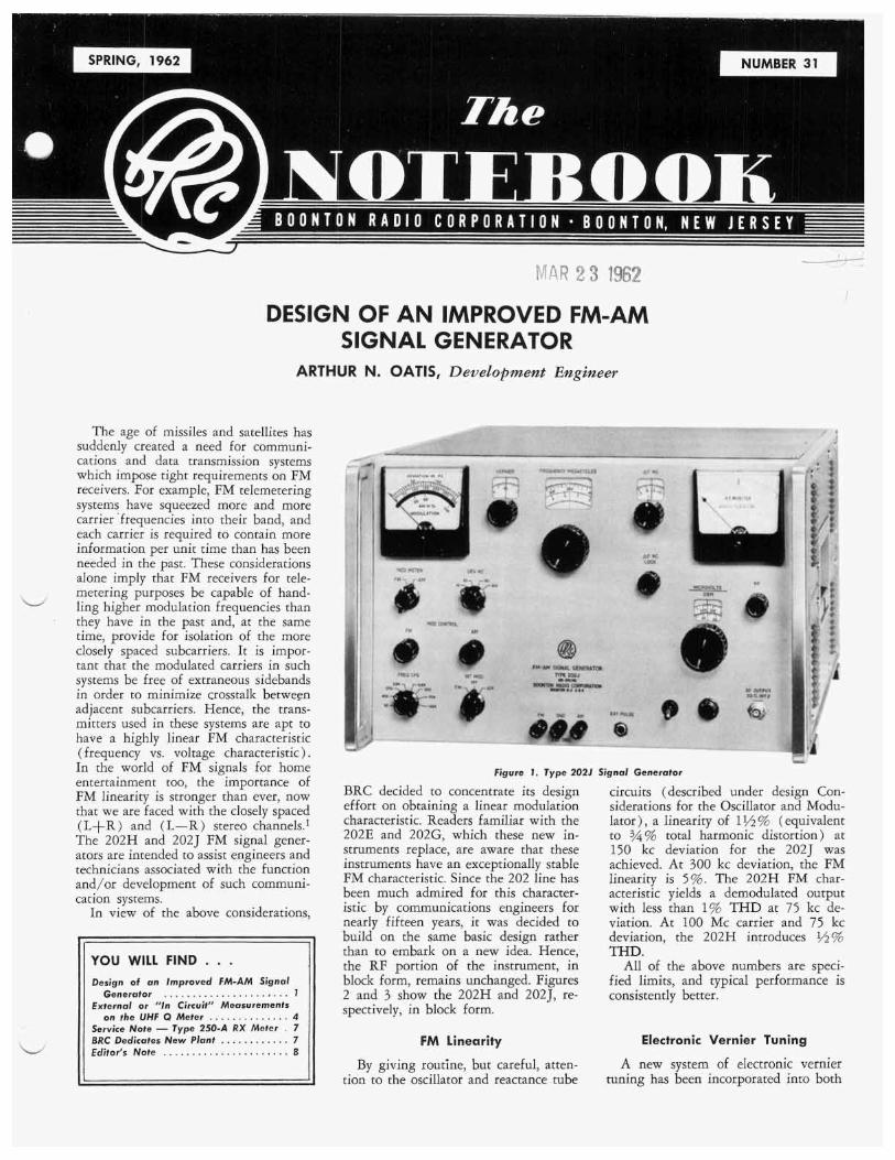
figure F. Type 2021 Signal Generator
BRC decided to concentrate its design effort on obtaining a linear modulation characteristic. Readers familiar with the 202E and 202G, which these new in- struments replace, are aware that these instruments have an exceptionally stable FM characteristic. Since the 202 line has been much admired for this character- istic by communications en nearly fifteen years, it was decided to build on the same basic design rather than to embark on a new idea. Hence, the RF portion of the instrument, in block form, remains unchanged. Figures 2 and 3 show the 202H and 202J, re- spectively, in block form.
FM Linearity
circuits (described under design Con- siderations for the Oscillator and Modu- lator), a linearity of 1 to %% total harm 150 kc deviation for the 202J was achieved. At 300 kc deviation, the FM
. The 202H FM char- acteristic yields a demodulated output with less than 1% THD at 75 kc de- viation. At 100 Mc carrier and 75 kc deviation, the 202H introduces 1/2% THD.
All of the above numbers are speci- fied limits, and typical performance is consistently better.
Electronic Vernier Tuning
By giving routine, but careful, atten- tion to the oscillator and reactance tube
A new system of electronic vernier tuning has been incocporated into both
B O O N T O N R A D I O C O R P O R A T I O N
T H E BRC NOTEBOOK is published four times a year by the Boonton Radio Corporajion. I t is mailed free o f charge to scientists, engineers and other inter- ested persons in the communications and electronics fields. T h e contents may be reprinted only with written permis- sion f r o m the editor. Your comments a n d s u g g e s t i o n s a r e w e l c o m e , a n d should be addressed to: Editor, T H E B R C N O T E B O O K , B o o n t o n R a d i o Corporation, Boonton, N . J .
the new 202H and 2025 to permit rela- tively small calibrated changes in output frequency. This system operates by ap- plying dc voltage to the grid of the reactance tube through a precision po- tentiometer. The total range of the con- trol is +40kc. The calibrated dial covers the range of 230kc in lkc increments and may be slipped against the poten- tiometer shaft by operating a dial lock mechanism. A jack is also provided for inserting external dc voltage for use in connection with an external X-Y plotter or frequency control system.
Microphonics and Vibration
Potentially, vibration and sound are two of the main sources of disturbance in low deviation measurements. Design of the 202H and J is aimed at alleviat- ing this problem. Figure 4 shows the mounting of an RF unit in the 202J and H. The unit is supported by four vibration absorbing mounts. Bellows- type, flexible couplings isolate the shafts of the main tuning capacitor and of the attenuator’s piston from the front panel. The net result is that the FM sensitivity of the 202H and J to acoustic or me- chanical impulses, applied to the front panel or to the mounting hardware, i s five times less than that of the 202E and G, Thus, the short-term frequency stability is much improved in all but the most quiet environments.
Automatic Level Set
The modern tubes used in the am- plifier and doublers of the RF unit pro- vide enough reserve RF power output to operatk a level control circuit. The out- put meter remains within *2% of the “red line” setting (for 0.2 volts maxi- mum output) across the frequency band.
Power Supply
The new generators contain regulated dc power supplies (both plate and fila-
MODULATION
I I LEVEL METER
REF.() LEVEL
Figure 2. Block Diagram of Type 202H
ment) for all rubes in the RF unit. As 3. The 202H power supply contains a result of these regulated supplies the neither a ballast tube nor a VR tube, residual FM at line frequency in the both of which components are 202J is less than half as much as it is vulnerable. in the 202G.
In order that the entire instrument be contained in a single package with- out excessive heating of the RF unit by the power supplies, all active com- ponents of the power supplies are semiconductors.
There are three basic improvements in the 202H over the 202E supply. 1. The power supply and signal gener-
ator are contained in a single cabinet. 2. Both supplies are more stable (by a
factor of 5 ) , with respect to line voltage fluctuations, than are their counterparts in the 202E.
d
FM Bandwidth of 2025
A need for wide bandwidth arises particularly in PCM telemetering sys- tems. The maximum IRIG Telemeter- ing standard bit rate is 330kc in the VHF band, and the receiver IF band- width requirement for this bit rate is about 500 kc. Hence, the bandwidth of an FM Signal Generator for checking a receiver’s ability to handle such signals should be more than 500 kc. The 202J has a 1 mc FM bandwidth.
MODULATION METER (PEAK TO
PEAK)
OOFF EXT. MOD. L A r - 0 A M - 0 FM
FM
4
RF DOUBLER DOUBLER OUTPUT PISTON
97.5- --c 195- -- 135MC 270 MC
I 195-270 MC
DETECTOR L A 0
REF. 6 LEVEL
Figure 3. Block Diagram of Type 202J
,-
W
2
~-
T H E N O T E B O O K
Peak Reading Modulation Meter Circuit for 2025
The modulation meter circuit is en- tirely new for the 202J. It reads the peak-to-peak deviation for all modula- tion waveforms which do not have im- portant frequency components outside the pass band of 10 cps to 1 mc. The circuit consists of a two-stage, feedback amplifier, followed by a peak-to-peak voltmeter circuit.
The 202H has the same kind of aver- aging meter circuit as the 202E it re- places, with two exceptions: the diodes in the 202H meter circuit are more stable, and the dependence of the meter reading stability on diode stability has been reduced by amplifying the signals to be measured before metering them.
In order to ensure a net gain in over- all meter accuracy, the amplifier has been heavily stabilized by negative feed- back.
W
Design Considerations for the Oscillator and Modulator
The basic BRC 202 frequency modu- lator is now, as it always has been, a reactance tube with a bridged-T phase shift network. One of the merits of this type of network is that it allows rela- tively little variation of deviation sensi- tivity with carrier frequency. The small variation in FM sensitivity is diminished by ganging one of the passive elements in the phase shift network to the tuning capacitor in the oscillator. An analysis of the action of the bridged-T and other phase shift networks used with -
ISOLATING w.COUPLING
Figure 4. Type 2021 - Top V i e w
reactance tube frequency modulators has been given by M. Crosby and D. Hill.' Within this framework, the improved FM linearity in the 202H and J has been achieved with no loss of constancy of FM sensitivity or carrier frequency stability.
In the process of developing an FM oscillator, one must be sure that, at every frequency in the tuning band, the oscil- lator operates at a frequency fairly close to resonance of the LC circuit. If, at some frequency in the band, the oscilla- tor departs from this frequency, then the impedance of the LC circuit contains an equivalent parallel reactance at that frequency. Of course, this kind of action does not prevent us from frequency modulating the oscillator, but it does re- sult in rather violent changes in FM sensitivity at some points in the band.
Occasionally one finds a carrier fre- quency close enough to a point of dis- continuity to be traversed in the modu- lation cycle. We still modulate the in- ductance of the LC circuit as planned, but the departure of operating frequency from resonance is now varying during the cycle. This is not the kind of be- havior one would care to make allow- ances for. Therefore, great pains were taken to design the oscillator-reactance tube combintaion such that these effects were minimized. The oscillator was loaded as lightly as practicable by the phase shift network, for example.
In the interest of FM linearity, the oscillator level is rather low so that its phase shifted output cannot drive the reactance tube outside of its linear region.
Tube type 6688 was chosen for the reactance tube and doubler stages, pri- marily because of its high stability and high trans-conductance. It has the added merit of low input conductance in the VHF band.
New Packaging
Both of these new signal generators are packaged in a restyled cabinet which can be readily rack-mounted. The front panel RF output jack can also be readily installed in a mounting hole, provided in the rear cabinet panel, for rack- mounted applications. Convenient carry- ing handles are provided on the sides of the cabinet in addition to the standard rack handles integral with the side frame castings.
Specifications
The following specifications apply to both the Types 202J and 202H, unless otherwise indicated.
RADIO FREQUENCY CHARACTERISTICS RF Range: 195-270 MC (202J) 54-216 MC (202H) No. Bands: 1 (202J) 2 (202H) Band Ranges: 195-270 MC (202J) 54-108 MC, 108- 216 MC (202H)
Main Dial: 10 .5%* Electronic Vernier: &( lo% +1 KC)* *after one hour warm-up
RF Accuracy:
RF Calibration: Main Dial: Increments of 0.5 M C (202J and 54-
108 MC on 202H) Increments of 1.0 MC (108-216 MC on 9 f l 7 H I
Mechaniral Vernier: 2200 divisions through range (202J) 2300 divisions through range (202H)
Electronic Vernier: Increments of 1 ,KC over 2 3 0 KC range* *total range -t40 KC; provision for slipping dial
to olace "0" at a specific frequency RF Stability:
0.02% per hour* (202J) 0.01% per hour* (202H)
*after two hour warm-up
Range: 0.1 pv to 0.2 volts* *across external 50 ohm load at panel iack Accuracy: -t1O0/o 0.1 pv to 50 K pv
Auto Level Set: holds RF monitor meter to "red line" over band Impedance: 50 ohms VSWR: 1.2 Spurious Output: All spurious RF output voltages are at least 25 db below desired fundamental an 202J (30 db on 202H)
RF Leakage: Sufficiently low to permit measure- ments at 0.1 pv
RF Output:
f200,: 50 K pv to 0.2 volts
llllrlllUli "-_I" ,D
External: 0-100% A M Accuracy: f 1 0 % at 30% and 50% A M A M Calibration: 30, 50, 100% A M Distortion: 5% at 30%
8% at 50% m o L -+ in no^
AMPLITUDE MODULATION CHARACTERISTICS A M Range:
A M Accuracy: f 1 0 % at 30% and 50% A M A M Calibration: 30, 50, 100% A M Distortion: 5% at 30%
8% at 50% 20% at 100%
Internal: 0-50% External: 0-100%
A M Fidelity: & 1 db, 30 cps to 200 KC
FREQUENCY MODULATION CHARACTERISTICS FM Range:
Internal: 0-300 KC in 4 ranges (202J) 0-250 KC in 4 ranges (202H)
External: 0-300 KC in 4 ranges (202J) 0-250 KC in 4 ranges (202H)
*indication proportional to peak-to-peok and sine-wave (202H) of modulating farm
FM Accuracy: 25% of full-scale* (202J) wave-
3
B O O N T O N R A D I O C O R P O R A T I O N
FM Calibration: 2025
0-15 KC in increments of 0.5 K C 0-30 KC in increments of 1 KC 0-150 KC in increments of 5 KC 0-300 K C in increments of 10 KC
0-7.5 KC in increments of 0.5 KC 0-25 KC in increments of 1 KC 0-75 KC in increments of 5 KC 0-250 KC in increments of 10 KC
at 300 KC (202J) *“leost squares“ departure from straight
202H
FM Non-Linearity*: 1.5% at 150 KC,
passing through origin FM Distortion: 0.5% at 75 K C (100 MC and
cps modulation only) 1% at 75 KC (54-216 MC) 10% at 240 KC (54-216 MC)
FM Bandwidth: f 3 db, 3 cps to 1 MC (202J) FM Fidelity: -C1 db, 5 cps to 500 KC (202J)
i l db 5 cps to 200 KC (202H) Spurious FM: Total RMS spurious FM from 60 cps power source i s at leost 60 db below 150 KC
Signal-to-noise Ratio: 60 db below 10 K C (202H) Microphonism: Extremely low; shock-mounted RF
Externol FM Requirements: 1 volt RMS into lOOK
(202H)
(202J)
unit
ohms for 150 KC deviation
5%
line
400
PULSE MODULATION CHARACTERISTICS PM Source: External PM Rise Time: 0.25 hsec PM Fall Time: 0.8 p e c
30 volts approx. at external FM posts 30 volts approx. at external AM posts
ACCESSORIES Furnished: Type 502-8 Patching Cable Avoiloble: Type 207-G Univerter (202J)
Type 207-E Univerter (202H) Type 501-8 Output Cable Type 504-A Adapter Type 505-8 Attenuator Type 506-8 Patching Cable Type 507-8 Adapter Type 508-B Adapter Type 509-8 Attenuator Type 510-8 Attenuator Type 514.8 Output Cable Type 517-8 Output Cable
PHYSICAL CHARACTERISTICS Mounting: Cabinet for bench use; readily adaptable
Finish: Gray engraved panel; green cabinet (other
Dimensions: Height: lO3/8” Width: 163h” Depth:
Weight: Net: 45 Ibs.
for 19“ rock mounting
finishes available on special. order)
18%”
POWER REQUIREMENTS 105-125/210-250 volts, 50-60 cps, 100 watts
References 1. John P. Van Duyne, “A Modulator for
the New FM Stereo System,” BRC Note- book Number 30.
2. M. G. Crosby and D. M. Hill, “Design of FM Signal Generator,” Electronics, Nov., 1946, pages 96-101.
EXTERNAL OR ”IN CIRCUIT” MEASUREMENTS ON THE UHF Q METER
CHARLES W. QUINN, Sales Engineer
Detailed information about the,design and theory of operation of the UHF Q Meter Type 280-A is given in Notebook Number 27. Conventional applications are covered in detail in Notebook Num- ber 28. An article concerning calibration of the instrument appears in Notebook Number 29. This article will deal specif- ically with the “unconventional” external or “in circuit” applications.
Basic Theory of Measurement Briefly, the UHF Q Meter utilizes the
bandwidth relationship Q = - (for
QZlO) to determine Q, as shown in Figure 1. A resonance indicating meter is used to determine the peak of the resonance curve and to resolve the half- power (.707V) points. This means that the UHF Q Meter reads Q in terms of frequency; the frequency being deter- mined by the ability of the instrument to measure a relutive amplitude change of 3db. The absolute value of V in Figure 1 is of no consequence and may
f o
Af
Figure Y . Q Resonance Curve
vary over a few decades (depending on the coupling of the probes and gain) without affecting the ability of the in- strument to read circuit Q.
Type 580-A Probe Kit In order to provide a convenient
means of coupling into the external
resonators or circuits, BRC has designed a probe kit (Type 580-A) which is suitable for many external measure- ments. The kit consists essentially of an injection probe and a detection probe, designed for coupling the external cir- cuits to the output of the oscillator and the input to the chopper amplifier in the 280-A. For external measurements, the Q capacitor and associated coupling circuits in the UHF Q Meter are dis- connected at the rear of the instrument and tkie injection and detection probes, furnished with the probe kit, are con- nected in their place. A basic block dia- gram of the UHF Q Meter, connected for external measurements, is shown in Figure 2.
Methods of Coupling to Test Circuits
Before discussing some of the tech-. niques for “in circuit” measurements, it would be well to point out two basic requirements which should be met by the external circuit to be measured. First, the circuit must be resonant in the fre- d
4
THE N O T E B O O K
Q CAPACITOR ASS’Y
Q CAP.
RESONANCE INDICATOR
J5 J4 _ _ _ _ _ _ _ _ - - - t
P h v o r ATTEN-,.. -.,, I IN
4 z W I- X W
a - ~---------------------------- Figure 2. Block Diagram of UHF Q Meter Showing Connecfions For External Measurements
280-A osc.
280-A osc
quency range of the 280-A (210 to 610 Mc) . Secondly, the Q of the circuit must range from 10 to 25,000.
Figure 3A shows a typical amplifier configurtaion with a tuned coaxial res- onator used as a plate load. This circuit may be measured using both the injec- tion and detection probes in the Type 580-A Probe Kit, since it has access holes large enough for insertion of both probes. A preselector resonator could be similarly measured.
Figure 3B demonstrates another tech- nique where an existing or “built in” loop is use for injection into the circuit to be measured and the 580-A detection probe is inserted into an access hole. In this case, care must be taken that the 280-A oscillator load does not exceed a 1.2 VSWR, referred to 50 ohms.
In Figure 3C the 580-A Probe Kit is not used. Existing or “built in” injection and detection circuits are connected di- rectly to the 280-A oscillator and chop- per amplifier circuits. When using this technique, the law of the detector used must be evaluated and taken into ac-
connecting a signal generator to the de- tector and using the variable attenuator
point on the 280-A resonance indicating meter. A precision 3db attenuator, con- nected in series with the signal genera- tor, be used for a more precise check of the detector.
Figure 3D illustrates still another technique for measuring an external cir- cuit. The 280-A oscillator is connected to a tube input circuit, which may be “hot” or “cold”, and the detection probe is connected at the output connector. This type connection is especially de-
sirable where it is necessary to evaluate the effects of dynamic loading. For this
should be relatively broad.
This may be accomplished by measurement the input circuit
From the foregoing, it can be seen
couple into the external circuits for performing “in circuit”
on the 280-A; serving an extremely broad range of applications.
Resonator Measurements The configurations of resonators in
the frequency range of the 280-A are varied. A few of these configurations are shown in Figure 4. When perform- ing resonator measurements it should be
in the signal generator to set the 3db that there are many techniques which may be used
280-A osc.
c “ 2 8 0 - A
CHOPPER AMPL.
280-A OSC “D”
Figure 3. Coupling Techniques
remembered that the resonators should be coupled to the 280-A at points which provide optimum coupling, wtih mini- mum loading by the 280-A. Basically, magnetic couplirlg is optimum at the Voltage Node point, or point of maxi- mum current; Le., the low 2 point. De- tection is optimum at the Current Node point or the point of maximum voltage; Le., the high 2 point (Figure 4 ) .
Test Circuit Loading Minimum loading is accomplished
with the detector coupled as “loosely” as practical. The ,injection circuit, on the other hand, may be coupled much “tighter” without loading. The .extent of loading can be evaluated by making a series of Q measurements at different sensitivity levels and probe spacings. Higher Q readings are indicative of negligible loading. The measurement should, therefore, be made at the mini- mum sensitivity level at which negligible loading occurs.
Extension of 1 Range It is interesting to note that external
measurements permit the inductance range of the 280-A to be extended be- yond the specified 2.5 to 146 mph range of the internal resonating capacitor. Re- ferring to Figure 4G, if C were known, and could be adjusted to a value less than 4 pf (the minimum capacitance of the 280-A Q capacitor), the inductance range of the instrument could be ex- tended to as much as 2 ph. This may be accomplished using a high quality, small variable capacitor with a range of ap- proximately 0.2 to 3 pf and a Q of 200 or more.’The 580-A probes are con- nected as shown in Figure 2 for external measurements. Either of the following techniques may then be used. The capacitance required to resonate the in- ductor could be estimated and the vari- able capacitor set for this value, using the calibrated Q capacitor. C1 and Q1
would then be measured. Then, with the coil and capacitor placed approximately as shown in Figure 4G, the resonant frequency.and circuit Q (Qc) would be determined. The inductance of the coil would then be computed for the meas- urement frequency using the following equations:
5
B O O N T O N R A D I O C O R P O R A T I O N
f BUTTERFLY
A"
COAXIAL HELICAL RESFlNATOR RESONATOR
B C"
(13RSo- '"2" RESPNATOR q E"
"D" RESONATOR D"
W I lNJl LINE RESONATOR
"F" "LUMPED" RESONATOR
"G"
Figure 4. Typicul Resonator Configurations
Another technique for extending the in- ductance range of the 280-A involves adjusting the variable capacitor until the desired resonant frequency is indicated by the 280-A. Circuit Q ( Q c ) is then measured. The variable capacitance (C) and Q are then measured on the 280-A and th6 above equations are used to determine L and Q.
Test Circuit Shielding When small or unshielded resonators
are to be measured, it is often desirable to make use of shielding to minimize 'hand capacitance" and radiation effects.
This shielding may be in the form of a "work box" with built in supports for the 580-A probes, as shown in Figure 5 . A setup of this type would be useful for evaluating the inductor mentioned in the previous paragraph.
External Resonators as Jigs and Fixtures
Resonators, in various forms, have ap- plications in many fields. The "D" res- onator (Figure 4 D ) , because of its pe- culiar magnetic field, is used in the investigation of molecular resonances in the field of basic research to improve our understanding of materials. "C' type resonators could be used for the measure- ment of dielectrics where the specimen is inserted into the gap that forms the resonating capacitance. Helical reson- ators are used to investigate the effects of ionization of gases in the ion pro- pulsion field. The helical resonator will also be useful in the evaluation of micro-
Figure 5. "Work Box" used as Shield for ResQnutor Measurements
wave varactors, diodes, and other semi- conductors, where capacitance values are low and Q values are high.
The reentrant cavity or coaxial resona- tor is probably one of the most versatile resonators, since its performance can be readily calculated. It can serve as a fix- ture for evaluating dielectrics (Figure 6A) or magnetics (Figure 6B) in the frequency range of the 280-A (210 to 610 Mc).
DIELECTR!,C HOLDER A"
REL. PERME,ABlLlTY B
Figure 6.
Measurements Under Simulated Environmental Conditions
The coaxial and other type resonators may be used with the '580-A Probe Kit to provide thermal isolation between the specimen and the instrument. This would be of special interest to research and development people involved with tem- perature measurements.
Extension Probes for Small or limited Access Resonators
The 5SO-A Probe Kit utilizes a tele- scoping sleeve principle. The outside di- ameter of the inner sleeve is 0.430 inch. The outside diameter of the outer sleeve is 0.500 inch. These diameters may be too large for some special ap- plications, either because of the physical size or the effect this size would have on the circuit under test. For high Q circuits (100 or more), this situation
can be remedied by fabricating exten- sions for the probes, similar to the sam- ples shown in Figure 7A. This would permit measurements where the diameter of the access holes would be limited only by the diameter of the coaxial cable used.
4
Note that the length of these probe extensions must be such that their res- onant frequency is well above the res- onant frequency of the resonator being measured. Resonance of the probes may be checked by bringing them close to each other, with the external resonator removed, and sweeping the frequency through the point of measurement. If the probe extensions are functioning properly, no sharp slope in output in- dications should be observed.
SILVER PL. SOLID COAX
l c l " 4 INJ. PROB EXTENSION
"A"
S M A L L
C A P PROBE EXTENSION "8"
Figure 7 . Examples of Probe Extensions
Conclusion An attempt has been made here to
point up some of the techniques which could be used for performing external measurements of circuits and resonators with the Type 280-A UHF Q Meter. Doubtless there are many applications which have not been touched upon or that should be expanded upon. It is our intension to delve more into dielectric measurements, low and high temper- ature techniques, semi-conductor meas- urements, and magnetics, in future Note- book artic1es:In the meantime, we here at BRC would appreciate hearing from any of our customers who have measurement problems in this area or who have evolved new measurement techniques which could be applied to this versatile instrument.
a m . .
6
T H E N O T E B O O K
SERVICE NOTE
Modificution of Type 250-A for Reduced Signul level und
Increased Sensitivity
Reducing Signal level An improved method has been devised
for reducing the signal level at the termi- nals of the Type 250-A RX Meter for special applications where a low signal level is required. In the past, the signal level was lowered by inserting a 100K ohm potentiometer in the signal oscil- lator plate supply, as described on pages 16 through 18 of the 250-A instruction manual. This provided a means for vary- ing the oscillator plate voltage, thus re- ducing the signal oscillator output level. This system works satisfactorily for the most part, but occasionally a plate volt- age will be selected which will "shut-off" the oscillator.
"0" "A"
NOTES EXISTING CASL
The modification, together with a list of t h e p a r t s r e q u i r e d , is shown i n Figure 1.
Increasing Sensitivity When the signal level to the bridge
is reduced for special applications, as described above, increased detector sensi- tivity is often desirable. The sensitivity of the 250-A may be significantly in- creased by modifying the instrument as shown in Figure 2.1 The signal from IF amplifier V202 (GAG5 ) is connected to a jack at the rear of the 250-A cabinet. A VTVM, connected to this jack, ampli- fies the signal and serves as a null indica- tor which has improved sensitivity over the null indicator on the front panel of the 250-A. This improves the resolution of the C , and R,, dials and also results in improved resolution of the R, or X,, parameter which is occasionally the minor impedance in a measurement. (Minor impedance is defined as that im- pedance which contributes least to the amplitude and phase of the current in an RF circuit.)
Figure I . Modification for Reduced Signal Level
The new method provides for the con- nection of a fixed or variable external at- tenuator (or attenuators) in series with the RF signal source to the bridge. In order to provide a convenient means for connecting the attenuators in the signal circuits, the bridge and oscillator con- nections are made accessible at the rear of the instrument cabinet. These con- nections are jumpered for normal opera- tion. For special applications, the jumpers are removed and replaced with fixed or variable attenuators. In most cases, the attenuator is connected in place of jumper "A" (Figure 1) . In some in- stances, because of mixing in the test component, it would be desirable to at- tenuate both signals.
'This modification was suggested by H. Thanos of R.C.A., Somerville, N. J.
SHlEl MOUNT CLOSE TO CABL I F TRANSFORMER
STD. JACK MOUNT ON REAR OF 250-A zk VTVM
(H-P 400D OR EQUIV)
Figure 2. Modification for Increased Sensitivity
For best results, and to obtain opti- mum sensitivity, it is necessary to select mixer tube VlOl (6AB4) for minimum noise deflection (preferably less than one division on the VTVM) .
BRC DEDICATES NEW PLANT Friday, October 20, 1961 was a per-
fect day for the dedication of the new BRC plant. Nestled in the Rockaway Valley, against a backdrop of high hills ablaze with autumn-painted trees, the new plant was the center of scenic splendor.
On hand for the dedication ceremony were BRC employees; friends and busi- ness associates of BRC; members of the local, county, and state government; and executives from the Hewlett-Packard (BRCs parent company) family.
The dedication ceremony was presided over by Dr. George Downsbrough. Presi- dent of BRC. Guest speaker was Mr. David Packard, President of Hewlett- Packard. Mr. A. R. Post, Chief, Bureau of Commerce for the State of New Jersey, delivered a message of congratula- tions from the Governor of New Jersey.
A "ribbon-cutting" ceremony was held at the main entrance to the new plant, with cutting honors going to Mr. John V a n d e r m a r k , Mayor of Rockaway Township.
M r . John Vandermark, Mayor of Rockaway Township, N. J., cuts ribbon to officially open
the new BRC plant as Dr. George A. Downsbrough and
Mr. David Packard look on.
CORRECTION The vector diagram and accompanying
equation in Figure 2 of the article en- titled, "A Modulator for the New FM Stereo System," published in Notebook Number 30, are not correct. The correct diagram and equation are given below.
R,=2010g (2 ) 7
B O O N T O N R A D I O C O R P O R A T I O N T H E N O T E B O O K
EDITOR’S N O T E BRC to Show Four New
instruments at IRE (VISIT BOOTHS 31 01 -31 02)
This year, at the IRE show, BRC will show four new instruments: the new pletely redesigned cabinet. Types 202-H and 202-J FM-AM Signal Generators, the new Type 2 3 0 - ~ Signal Generator Power Amplifier, and the new Type 2 19-A FM Stereo Modulator.
solid-state power supply, and a com-
The 230-A Signal Generator Power Amplifier provides a means of increas- ing the RF power output of conventional signal generators up to 4 watts or +6 dbw ( 14 volts rms-into 50 ohms), in the
covers the frequency range of 54 to 216 The 219-A FM Stereo Modulator pro- Mc and replaces the Type 202-E. The vides the stereo modulation outputs, as 202-J blankets the 195 to 270 Mc tele- specified in FCC Docket 13506, suitable metering range and replaces the 202-G. for modulating FM signal generators, Improvements in these instruments in- such as the BRC Type 202-E or 202-H. clude: improved FM linearity, automatic A “Guess the Q” contest, which seems RF level set, electronic vernier tuning, to have become traditional with BRC, increased FM modulation bandwidth, will be a feature at the BRC booth again improved FM deviation metering, re- this year. Our engineers have been hard duced FM microphonism, a completely at work devising a “guess-defying” Q
The Type 202-H signal generator frequency range of 10 to 500 Mc.
circuit thar should be a delight and a
Visit booths numbers 3101 and 3102. See and hear more about our new instru- ments, and have the BRC engineers on duty help you with your test instrument application problems.
challenge to booth visitors. d
Photograph faken at a previous IRE show demonstrates that the BRC “mystery coils” put all of the Q contest entrants in a pensive mood.


![WM-FX141 - Electronica.ro...— 7 — [AM] BAND: AM Signal generator [FM] BAND : FM Signal generator AM TRACKING ADJUSTMENT Adjust for a maximum reading on level meter. L1 620kHz(800kHz)](https://static.documents.pub/doc/80x56/614525d334130627ed50ccd1/wm-fx141-a-7-a-am-band-am-signal-generator-fm-band-fm-signal-generator.jpg)


