Missouri University of Science and Technology Missouri University of Science and Technology Scholars' Mine Scholars' Mine Center for Cold-Formed Steel Structures Library Wei-Wen Yu Center for Cold-Formed Steel Structures 01 Aug 1983 Design of automotive structural components using high strength Design of automotive structural components using high strength sheet steels preliminary study of members consisting of flat and sheet steels preliminary study of members consisting of flat and curved elements curved elements Wei-wen Yu Missouri University of Science and Technology, [email protected]M. Brad Parks Follow this and additional works at: https://scholarsmine.mst.edu/ccfss-library Part of the Structural Engineering Commons Recommended Citation Recommended Citation Yu, Wei-wen and Parks, M. Brad, "Design of automotive structural components using high strength sheet steels preliminary study of members consisting of flat and curved elements" (1983). Center for Cold- Formed Steel Structures Library. 188. https://scholarsmine.mst.edu/ccfss-library/188 This Technical Report is brought to you for free and open access by Scholars' Mine. It has been accepted for inclusion in Center for Cold-Formed Steel Structures Library by an authorized administrator of Scholars' Mine. This work is protected by U. S. Copyright Law. Unauthorized use including reproduction for redistribution requires the permission of the copyright holder. For more information, please contact [email protected].
Transcript
Missouri University of Science and Technology Missouri University of Science and Technology
Scholars' Mine Scholars' Mine
Center for Cold-Formed Steel Structures Library Wei-Wen Yu Center for Cold-Formed Steel Structures
01 Aug 1983
Design of automotive structural components using high strength Design of automotive structural components using high strength
sheet steels preliminary study of members consisting of flat and sheet steels preliminary study of members consisting of flat and
curved elements curved elements
Wei-wen Yu Missouri University of Science and Technology, [email protected]
M. Brad Parks
Follow this and additional works at: https://scholarsmine.mst.edu/ccfss-library
Part of the Structural Engineering Commons
Recommended Citation Recommended Citation Yu, Wei-wen and Parks, M. Brad, "Design of automotive structural components using high strength sheet steels preliminary study of members consisting of flat and curved elements" (1983). Center for Cold-Formed Steel Structures Library. 188. https://scholarsmine.mst.edu/ccfss-library/188
This Technical Report is brought to you for free and open access by Scholars' Mine. It has been accepted for inclusion in Center for Cold-Formed Steel Structures Library by an authorized administrator of Scholars' Mine. This work is protected by U. S. Copyright Law. Unauthorized use including reproduction for redistribution requires the permission of the copyright holder. For more information, please contact [email protected].
3) space and layout limitations, and 4) increased compressive strength
over that of flat elements with similar dimensions.50
Because curved elements form such vital parts of modern automobiles
and because existing design procedures either lack the desired accuracy,
are extremely complex, or are of uncertain applicability to HSSS, the
present investigation was initiated to determine any possible methods
of improving the current design procedures for curved elements. In the
early stages of the investigation, all of the structural components con
sidered will be straight with uniform cross sections throughout their
lengths. This report is presented as an initial study of the compressive
2
behavior of curved elements and contains a summary of the available
literature on the subject. It is hoped that as a result of this initial
study and the proposed future research, simplified and accurate design
equations for the prediction of the compressive behavior of curved
elements made of HSSS can be developed.
The present study was performed as a part of the proposed tasks to
be conducted in Phase II of a three-phase research project entitled
"Structural Design of Automotive Structural Components Using High
Strength Sheet Steels". The project was started in early 1982 at the
University of Missouri-Rolla (UMR) under the sponsorship of the American
Iron and Steel Institute (AISI).
B. SCOPE OF INVESTIGATION
In Section II of this report, the literature on members with curved
cross sections is reviewed. Section II.A contains a discussion of the
behavior of individual curved plates when subjected to either elastic
or inelastic buckling. For each type of buckling, the possible equations,
which could be of some value for the prediction of the initial buckling
stress of curved plates, are given, and the expected post-buckling
behavior normally associated with each buckling type is discussed.
In Section II.B, the approximate design procedures, which have been
employed by the aerospace industry for compression members consisting
of both curved and flat elements, are discussed. After a brief discussion
of the two basic design procedures (the Air Force Method and Crockett's
Method), the two methods are compared. A few other related articles,
which might be useful for future studies, are also considered.
The effective width concept normally used for flat elements is reviewed
in Section II.C to provide background information for the possible
development of a similar effective width concept for curved elements.
Also, the sparse amount of literature available on the existing
effective width equations for curved elements is summarized.
In Section II.D, the available procedures for predicting the
buckling behavior of curved plates when subjected to shear loading are
analyzed. This information should be of some value for future studies
of beams with curved webs.
Section III contains a general summary of the future research needs
for the prediction of the compressive strength of curved plates and
sections composed of flat and curved elements. The information gained
through the literature review is summarized in Section IV.
3
4
II. PREDICTION OF CRITICAL BUCKLING STRESS OF CURVED ELEMENTS
A. COMPRESSION OF CURVED PLATES
The accurate prediction of the compressive strength of curved plates
is extremely complex. It seems that classical stability equations based
on linear theory are insufficient because they consistently overestimate
the critical buckling stress, f , of curved plates. The major causecr
of this overestimation is the fact that buckling of curved plates is
accompanied by compressive transverse membrane stresses, which result in
a deflected geometry that is unstable. For this reason, large deflection
theory is essential for reasonably accurate prediction of fcr It has
been observed that when compressive membrane stresses are produced
transverse to the direction of buckling, such as for the compressive
buckling of curved plates or cylinders, large deflection theory is required.
However, when tensile membrane stresses are produced perpendicular to the
direction of buckling, such as for buckling caused by lateral pressure on a
relatively short, closed cylinder, torsion on a cylinder, or compression
on flat plates, linear theory is sufficient to predict f .4cr
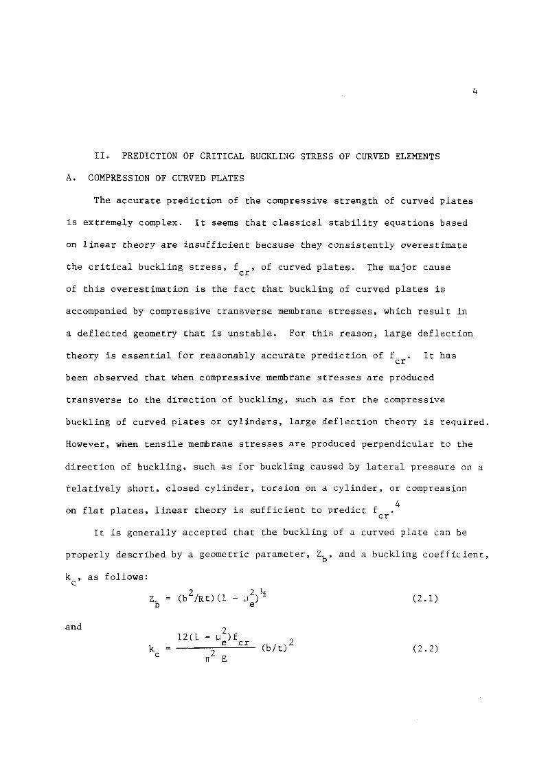
It is generally accepted that the buckling of a curved plate can be
properly described by a geometric parameter, Zb' and a buckling coefficient,
k , as follows:c
and
kc
212(1 - 1.1 )f___,.-:e~..::;c..:::.r_ (b It) 2
TI2 E
(2.1)
(2.2)
5.7, was used to plot
S
in which
E modulus of elasticity
t = curved plate thickness
R = radius of curved plate
b = circumference of curved plate
lle elastic Poisson's ratio
Figure 2.1 shows the relationship between kc
and Zb for a series
Sof compression tests made by Jackson and Hall on curved panels made
4of an aluminum alloy. Other similar test results are listed in Ref-
erences 6 through 11.
At values of Zb < 10, the behavior of curved plates is approximately
the same as that of flat plates with similar boundary conditions, and thus
the buckling coefficient, k , approaches that of a flat plate. The boundc
ary conditions applied by Jackson and HallS were between simple support
and clamped conditions. Therefore, an average of the buckling coefficients
for flat plates of these two limiting cases, kc
4the portion of the k
c- Zb curve for Zb < 10.
For values of Zb > 1000, long cylinder behavior dominates, and the
effects of boundary conditions are negligible_ By observing the relation-
ships in Equations (2.1) and (2.2), it can be seen that for large values of
Zb' the buckling coefficient appears to be linearly related to Zb- Thus,
the resulting equation takes on the form of the classical buckling equation
for cylinders:
fcr
C E t/ R (2.3)
6
in which C represents the slope of the relationship between f andcr
E(t/r).
It is within the intermediate range of 10 < Z < 1000, whereb
12boundary conditions still exert considerable influence on f , that
cr
extreme difficulty is experienced in predicting the critical buckling
stress. It seems obvious that some sort of transition curve must
exist between the two limiting cases described above. A few of the
more successful attempts to develop such a curve are described in
Section II.A.l.
The range of the various possible geometries of curved plates is
4illustrated in Figure 2.2. Of the possibilities shown in Figure 2.2,
only the extreme combinations of a long curved plate with large curvature
(e.g., a closed cylinder) and a short curved plate with small curvature
(e.g., a flat plate) are well researched and defined. All other com-
binations fall into the previously described transition range.
In the following sections, the elastic and inelastic buckling and
post-buckling behaviors of curved plates are discussed, and a brief
summary of some of the methods proposed for the prediction of buckling
is included.
1. Elastic Buckling.
a. Transition Equations. Many attempts have been made over the
years to develop a transition equation that would accurately predict
the critical stress of curved plates when the geometric parameters of
these plates lie somewhere between those of flat plates and complete
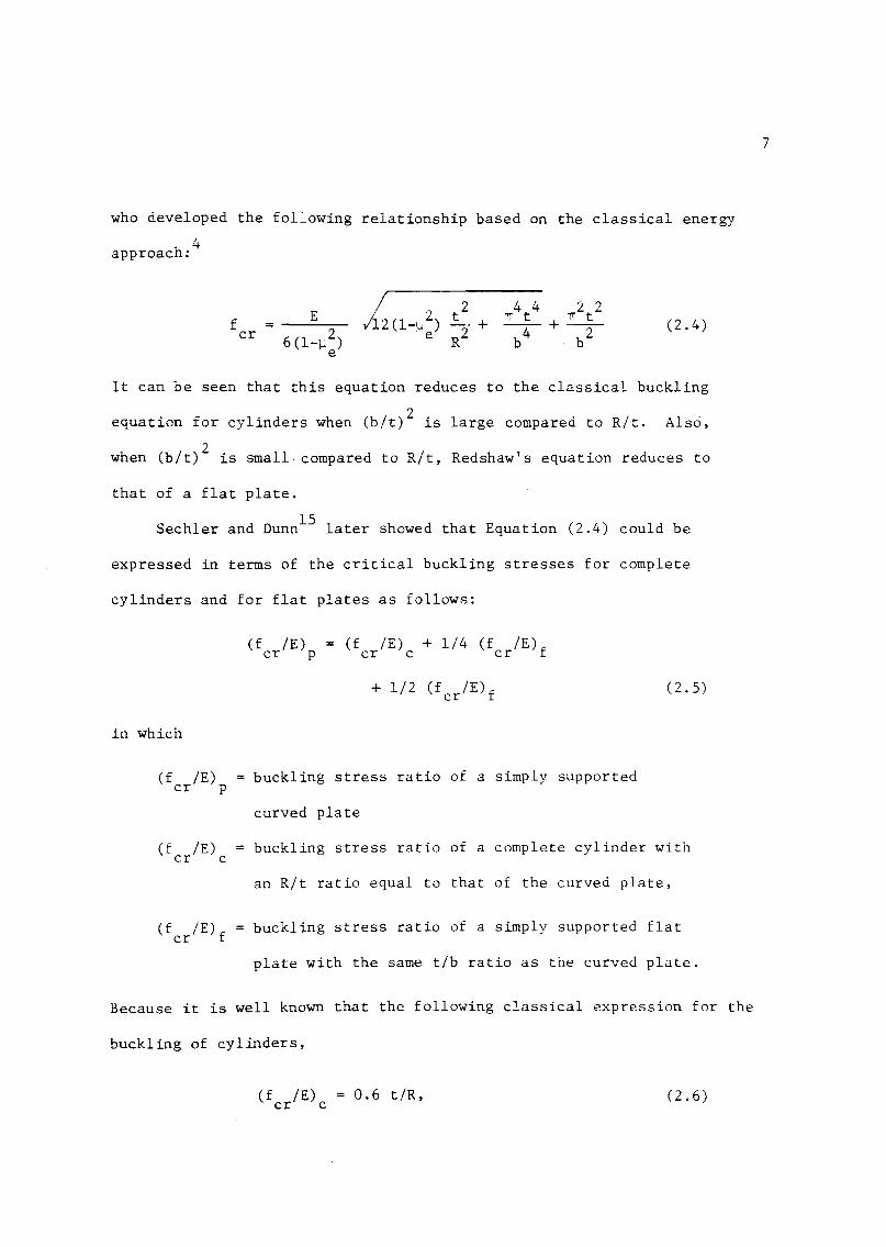
cylinders. One of the first such attempts was performed by Redshaw13 ,14
who developed the following relationship based on the classical energy
4approach:
7
(2.4)
It can be seen that this equation reduces to the classical buckling
equation for cylinders when (bit) 2 is large compared to R/t. Also,
when (b/t)2 is small compared to Rlt, Redshaw's equation reduces to
that of a flat plate.
15Sechler and Dunn later showed that Equation (2.4) could be
expressed in terms of the critical buckling stresses for complete
cylinders and for flat plates as follows:
(f IE) = (f IE) + 1/4 (f IE)fcr p cr c cr
in which
(f IE)cr p
+ 1/2 (f IE)fcr
buckling stress ratio of a simply supported
curved plate
(2.5)
(f IE)cr c
(f IE)fcr
buckling stress ratio of a complete cylinder with
an Rlt ratio equal to that of the curved plate,
buckling stress ratio of a simply supported flat
plate with the same tlb ratio as the curved plate.
Because it is well known that the following classical expression for the
buckling of cylinders,
(f IE)cr c
0.6 tlR, (2.6)
8
consistently predicts f values, which are as much as twice the actualcr
f values, Sechler and Dunn suggested replacing the classical value ofcr
(f IE) with the following empirical relationship:cr c
(f IE)cr c
0.3 t/R. (2.7)
Several other investigations into the development of transition
equations for curved plates have been performed. Among the more note-
16worthy are the semi-empirical investigations conducted by Stowell,
W k 17 d L' d' 10 L 18 h b ' f 1 d flenze, an l.n qUl.sts. . evy on t e asl.S 0 arge e ection
theory developed the equations required to predict f .cr
b. Post-Buckling Behavior. The post-buckling behavior for the
elastic buckling of curved plates depends on the geometry of the plates
and the magnitude of initial imperfections. It should come as no
surprise that just as for the initial elastic buckling, the post-buck-
ling behavior of curved plates also varies between the extremes of a
flat plate and a cylinder.
For Zb < 10, a curved plate acts much the same as a flat plate with
similar dimensions. Thus, as shown in Figure 2.3, the effects of initial
imperfections are insignificant, and the compressive load increases well
past f . The ultimate load is reached when the effects of plasticitycr
become predominant.
At values of Zb > 1000, the post-buckling behavior of a curved plate
should be similar to that of a cylinder. From Figure 2.3,12 it can be
seen that for cylinders, the load-carrying capacity drops off sharply
after initial buckling and never regains the original buckling stress
in the post-buckling range.
failure are coincident.
Thus, the initial buckling stress, f ,andcr
9
In the intermediate range of 10 < Zb < 1000, there is obviously
a transition between the post-buckling effects of flat plates and cylinders.
However, there are no known studies of the exact post-buckling behavior
of curved plates in this range.
2. Inelastic Buckling. If the various parameters described in
Section II.A are such that the critical buckling stress is greater than
the proportional limit of a given material, the buckling is said to be
inelastic, and an adjustment in the elastic buckling equations must be
made. (It is important to note that this type of buckling only occurs
for materials with gradual - yielding stress-strain curves. An example
of a typical gradual - yielding stress-strain curve is shown in Figure
2.4 (a). For sharp - yielding materials with stress-strain curves
similar to Figure 2.4 (b), elastic buckling prevails until f reachescr
the yield point of the mate~ial.) This adjustment is necessary because
the elastic buckling equations were developed under the assumption that
the stress and strain were linearly related. However, for stresses above
the proportional limit, the relationship between stress and strain is,
by definition, nonlinear. In order to account for the nonlinear stress-
strain relationship, the value of the modulus of elasticy, E, is altered
in the elastic buckling equations by means of a plasticity reduction
factor, n. Several different values of n have been studied by various
investigators. In the following sections, the available literature on
the different plasticity reduction factors is reviewed.
a. Plasticity Reduction Factors.
i. Tangent Modulus Method. 19In 1895, Engesser proposed that the
10
modulus of elasticity, which is the slope of the stress-strain curve in
the elastic range, should be replaced by the instantaneous slope of the
stress-strain diagram in the inelastic range. This instantaneous slope
is defined as the tangent modulus, Et
, as shown in Figure 2.5. Thus, in
the elastic range, Et
: E. In the inelastic range, the value of Et
is
substantially reduced. The value of the plasticity reduction factor for
this method is simply
n :E
t
E(2.8)
ii. Secant Modulus Method. This method is quite similar to the
tangent modulus method. The only difference is in the definition of
the secant modulus, E. The secant modulus is defined as the slope ofs
a line from the origin of the stress-strain diagram to the critical
stress. The value of E is illustrated in Figure 2.5. The plasticitys
reduction factor for this case is
Es
n : E (2.9)
The reduced modulus, E ,r
In the mid 1940's, Schuette,9 who used this method for curved plates
constructed of magnesium alloy materials, reported fair agreement bet-
ween the predicted and test results.
iii. Reduced Modulus Method. This method was originally proposed
by Engesser19 and later revised by von Karman.20
(also known as the double modulus) is a function of the original modulus,
E, the tangent modulus, Et
, and the shape of the cross section. This
modulus is derived from the equilibrium equations in the cross section
11
at the onset of buckling and, thus, is technically more correct than the
21tangent modulus method. The reduced modulus is defined as
Er (2.10)
in which II and 12
are the moments of inertia with respect to the neutral
axis of the tensile and compressive stresses caused by column instability.
For a more detailed description of the reduced modulus, the reader is
referred to the work of Bleich.22
According to Fischel,21 the reduced modulus for compression members
with rectangular cross sections, such as flat plates, may be expressed as
Er
Fischel reports
4EEt
(IE + lEt2
good correlation
(2.11)
between the test results of curved plates
made of aluminum alloy and the predicted values of f when Equation (2.11)cr
is used for the calculation of E .r
iv. Gerard's Method. Another method for reducing the modulus of
elasticity for inelastic buckling by means of a plasticity reduction
4factor is given by Gerard as
En = ~[
E
2(l-lJ ) E 1___;~ ~]"2
(l-\.l ) Es(2.12)
in which lJ = \.lP
( lJ - lJ )(E IE) and lJ = plastic Poisson's ratio. TheP" e s p
remaining terms have been previously defined.
9In checking the test data published by Schuette on curved plates
made of magnesium alloy, good agreement was obtained between the test
results and those predicted by using the above value of n. It is inter-
12
esting to note that in using this method, the accuracy of the predicted
results was better than the accuracy obtained when the secant modulus
method was used with the same data. 4
b. Post-Buckling Behavior. The approximate buckling and post
buckling behavior of flat plates and columns that buckle inelastically
is shown in Figure 2.3 (b). Again, depending on the value of Zb' the
behavior of curved plates would be expected to be somewhere between
that of a flat plate and a cylinder.
B. COMPRESSION MEMBERS CONSISTING OF FLAT AND CURVED ELEMENTS
Structural engineers are often faced with the problem of predicting
the local buckling stress of compression members composed of both flat
and curved elements. This problem is particularly evident for relatively
"short" columns for which the critical buckling load is normally governed
by local buckling or yielding of the individual elements of the cross
section. If test results are not readily available, the engineer usually
determines the strength of the given cross section based on the summation
of the local buckling strengths of the individual flat and curved plate
elements. 15 ,23-25 This procedure is desirable because the buckling stress
of each of the curved and flat- elements may be predicted by using existing
equations. The boundary conditions of the elements are assumed to be either
simply supported, if they are bounded by other elements, or free. Figure
2.6 illustrates the assumed boundary conditions for some typical cross
sections.
Because it has been noted that, unlike flat elements, curved elements
typically exhibit very little post-buckling strength, the cross section
is assumed to have failed when the cricical stress is reached in a curved
13
element of a given cross section. Two methods found in the literature
for predicting the critical stress of cross sections composed of flat
and curved elements are reviewed in the following discussion.
1. Air Force Method. This method was originally published by
Newell and Sechler24 and can best be described by the following example:
If, in the cross section shown in Figure Z.6(b), f 3 < f 1 andcr cr
f < f 2' then the critical stress will becr3 cr
f cr =fcr3C2Al + 2AZ + A3)
ZAI
+ ZA2
+ A3
fcr3
(Z.13)
If f 1 < f 3 and f 2 > f 3' the critical stress will becr cr cr cr
fcr
fcd
C2AI
) + fcd
(2A2
+ A3
)
ZAl
+ 2AZ
+ A3(2.14)
If f 1 < f and f 2 <cr cr3 crf 3' the critical stress will becr
fer =fcrl ( 2AI ) + fc r 2 ( ZA2) + fc r3 (A3)
ZAl
+ 2AZ + A3
(2.15)
The maximum value of any of the above stresses is limited to the yield
strength of the material.
2. Crockett's Method. A slightly different approach for predicting
the critical stress of this type of cross section has been introduced by
Crockett. 25 Crockett's method is based on a series of tests on aluminum
sheet stiffeners when used alone or in combination with aluminum sheets.
The test results obtained with this method for the most part are within
15 percent of those predicted. The basic equation used to predict the
critical stress is as follows:
in which
F = Kcc
I b t fn n cn
I b t = K Fccln n
(2.16)
14
Fcc final predict~d crippling stress, psi for 1/P < 20
Fccl uncorrected predicted stress = I b t f II b t
n n cn n n
K = the stability shape factor given in Table 1
bntn area of individual element, sq. in.
f = average ultimate stress of the individual element,cn
given empirically by Figures 2 and 3 of Ref. 25
for flat and curved elements, respectively, psi
p = the radius of gyration of the stiffener along
about an axis parallel to the sheet in a stiff-
ener-sheet combination, in.
1 = length of stiffener or panel, in.
The variations of K for the various cross sections are shown in Table
2.1. 25
3. Comparison of the Air Force Method and Crockett's Method. There
are two basic differences between Crockett's method and the Air Force
method. The first is the introduction of the stability shape factor,
K, by Crockett, which accounts for the differences in cross sectional
shapes. The other is that Crockett's method does not limit the critical
stress in the cross section to that of the curved elements.
Because there is only a limited amount of published test data on
the compression of cross sections with flat and curved elements~ it is
IS
difficult to make any broad assumptions about the accuracy of either
method. It does seem that the stability shape factor suggested by
Crockett would be desirable because it is obvious that cross sections
with sloped elements would be less stable than those composed of
straight elements. However, the fact that Crockett does not limit
the critical stress of the cross section to that of the curved elements
appears undesirable because curved elements are noted for their small
post-buckling strengths.
In any event, the authors of both methods suggest that these pro-
cedures be used only to determine preliminary designs. The adequacy
of the final designs should be proven by tests.
4. Additional Literature. Other procedures, which may be useful
for computing the compressive strength of members composed of flat and
curved elements, consist of 1) an equation for the prediction of the
26compressive buckling stress of a curved flange by Buchert, 2) a
method developed by Needham27
for compression members composed entirely
of flat elements in which he divided the cross section into a series
of angles in order to account for the cold work effect in the cold
12formed corners, 3) an empirical approach used by Gerard who presented
the critical buckling stress in terms of the number of corners in the
cross section, and 4) the design criteria given by the Aluminum Associa
tion in the "Specification for Alumimnn Structures,,28 for aluminum curved
plates and elements.
C. EFFECTIVE WIDTH OF COMPRESSION ELEMENTS
The concept of an "effective width" was orginally introduced by
16
von Karman et al.29
to simplify the calculations needed to predict the
ultimate strength of flat plates. Since that time, there has been
a considerable amount of research performed in this area for flat
plates; however, the research data for curved plates are quite limited.
Therefore, in the following sections, the effective width concept for
flat plates is discussed to provide background information for future
studies of the effective width of curved plates. Also the available
studies on the effective width of curved plates are briefly reviewed.
1. Flat Plates. For flat plates, which are supported on four
sides, such as the upper flange of a hat section, the stress distribution
after buckling becomes nonuniform with the maximum stress occurring along
the supported edges. With the application of more load, the maximum edge
stress increases until the yield strength of the material is reached. At
this point, the maximum post-buckling strength of the plate is normally
30assumed to be reached. Figure 2.7 illustrates the different stress
distributions in the plate as the load is progressively increased.
The effective width is defined as an imaginary width of plate, b ,e
., 30(as shown ln Flgure 2.8) ,which, when loaded with the maximum edge
stress, f ,resists the same ultimate load as the full width platemax
described above. In other words,
o
w
f fdx = b fe max(2.17)
Because the actual stress distribution, f, across the full width of
the buckled plate is not easily determined, approximate methods are
employed to determine the effective width.
29In 1932, von Karman suggested that the effective width, be' can
be approximated as the width of plate, which buckles just when the
compressive stress reaches the yield point of the material. Therefore,
based on this assumption, the effective width may be derived from the
theoretical equation for the buckling of flat plates by setting
f F , i.e.,cr y
17
f = Fcr y(2.18)
Thus,
in which
b = Cte
11="F
y1. 9t ;:i
Fy(2.19)
0.3
1.9
t flat plate thickness
Based on an experimental investigation conducted by Winter3l
and
30,32much experience in the design of flat plates, the constant, C,
given in Equation (2.19) has been modified such that the revised effect-
ive width equation is as follows:
/-E- t ;-E-
be= 1.9t -f---[1-0.415(b) -f---]
max max(2.20)
Equation (2.20) is currently used in the American Iron and Steel
Institute (AISI) Specification33
for the design of cold-formed, flat
compression elements with both unloaded edges supported.
18
An equation similar to Equation (2.20) was developed by Winter3l
for the effective width of cold-formed, flat compression elements with
only one of the unloaded edges supported and the other unloaded edge
free. This equation is
b = 0.8t 1/ [ 1-0.202(~) 1/ ].e max max
(2.21)
Add " 1 h d d C 11 u· . 34-36 h h d~t~ona researc con ucte at orne n~vers~ty as s own goo
agreement with Equation (2.21).
It should be noted that the current AISI Specification for buildings33
does not use the effective width concept for compression elements with one
unloaded edge supported and the other free. Instead, the present Specifica-
tion has chosen to use an allowable stress approach for flat plates with
this type of boundary condition.
2. Curved Plates. As stated earlier, the available research data on
the effective width of curved plates are limited. For values of Zb < 10,
Levy18 showed that on the basis of a theoretical analysis, the effective
width of curved plates is not appreciably different than for flat plates.
This is not surprising because for buckling considerations, it has been
shown in Section II.A that for Zb < 10 the behavior of flat and curved
plates is practically identical.
37Based on the test data collected by Ramberg ~ al. for aluminum
alloy curved plat~s, the effective width is approximately given by
b eb
~ t (_E_)~== Kc b f .
e
(2.22)
in which
be = effective width of curved plate
b = circumference of curved plate
t = thickness of curved plate
f = edge stresse
19
Kc
TI2
k= __---::;c"7" • k
2 'l2(1-j..l) cas determined in Ref. 21
It should be noted that the above equation is good for Zb ranges
of 0 to 10 and 24 to 32 and for effective width ratios, be/b, in the
22range of 0.45 to 1.0.
For effective width ratios less than approximately 0.45, the test
. 5data obtained by Jackson and Hall for aluminum alloy curved plates
seem to exhibit the following relationship for effective width:
be
b(2.23)
in which
K = buckling coefficient for flat plates, for a long platep
with clamped edges K = 6.3P
The data that form the basis for Equation (2.23) are obtained for
o < Zb ~ 125.
Gerard 12 warned that Equations (2.22) and (2.23) should be used
with caution for Zb > 30 because of the limited range of Zb in the
tested specimens.
Another method for using the effective width concept to predict
the ultimate strength of curved panels is given by Sechler and Dunnl5
38and is applied in similar form by Barton. For this method, the
effective width is defined in exactly the same manner as previously
described for flat plates with the same developed width. However,
unlike flat plates, curved panels are assumed to carry the critical
buckling stress of a circular cylinder (with the same thickness and
radius as the panel) over the width of panel between the assumed
boundaries of the effective width. The assumed post-buckled stress
distribution is shown in Figure 2.9.38
Thus the ultimate load carrying
capacity, P l' is given bytota
20
P = b t f + (b - b ) t .ftotal e max e c
in which
(2.24)
be = effective width of curved plate determined in the same
manner as a flat plate with the same dimensions
f maximum edge stress along the supported edgemax
f = the critical buckling stress of a complete cylinderc
with the same thickness and radius as a curved panel
t = thickness
15In Table 8.2 provided by Sechler, the results of tests performed
on aluminum curved panels at the Massachusetts Institute of Technology
are compared to the values predicted by Equation (2.24) with f setmax
equal to the yield stress of the material. The range of P IPtotal test
was found to vary from 0.77 to 1.37; however, in most cases, the values
of P and P did not differ by more than 10 percent.total test
15By using the data presented in this Table ,the range of Zb was
calculated to be 8.4 to 687. For values of Zb appreciably greater than
21
this range (i.e. Zb > 1000), there seems to be little use for the
effective width concept because initial buckling and failure are
coincident. 18According to Levy, other studies of the post-buckling
t th f d 1 . b K d· 39,40s reng 0 curve pates are g1ven y von armon an TS1en, Cox
41 42 43 17and Clenshaw, Newell, Ebner, and Wenzek.
D. CURVED PLATES SUBJECT TO SHEAR LOADING
1. Unstiffened Curved Plates. The buckling stress for an un-
stiffened curved plate loaded primarily in shear, such as the curved
web of a beam, is considerably greater than the buckling stress for
a flat plate of the same dimensions.44
Just as for the axial compression
of curved plates, the theoretical buckling stresses are usually greater
than those obtained experimentally. The following theoretical buckling
45stress equation was derived by Batdorf ~ ale for the theoretical shear
buckling stress, f , for curved plates:cr
f = K E (t/b)2cr s
(2.25)
in which K is a function of the length, circumference, radius, ands
thickness of the curved plate.
46An empirical equation has been proposed in ANC-5 as:
2f = K E (t/b) + Kl E (t/R)cr
(2.26)
in which the first term represents the buckling stress for a flat plate,
and the last term the additional shear stress that the curved plate
can resist because of its curvature. A value of Kl = 0.10 is recom-
46mended.
22
2. Longitudinally Stiffened Curved Plates. There has been some
study of curved plates with longitudinal stiffeners in which the "tension
field,,44 concept is employed in a similar fashion to the tension field
analysis of thin flat webs in straight girders. In the pure tension
field concept, as proposed by Wagner and Ballerstedt,47 the curved plate
is assumed to be completely flexible. Thus, its compressive strength is
considered negligible, and the curved plate is assumed to buckle freely
at an angle of 45° to the shear stress (i.e., the direction of maximum
compressive stress caused by pure shear). Because even very thin, curved
webs have appreciable in-plane stiffness, this assumption is generally
considered invalid. Thus, a "semitension field" analysis is normally
employed in which the compressive stiffness of curved webs is taken into
consideration. Semiempirical methods of analysis and design for long
itudinally stiffened curved webs are given by Kuhn and Griffin.48
III. FUTURE RESEARCH NEEDS
Since curved elements are used throughout a modern automobile,
accurate, yet relatively simple, design eguations for these elements
are essential. Because of the mathematical complexities involved in
the accurate analytical prediction of the critical buckling stress of
curved elements, it is believed that any practical design expressions
must be empirical or at least semi-empirical in nature. Since there
is a limited amount of available test data for curved elements, several
additional tests are proposed in this Section.
The proposed test specimens (Figures 3.1 through 3.4) represent
typical, simplified cross sections (or profiles) that are normally
utilized in automobiles. These specimens will be formed from the same
high strength sheet steels used in Phase I of the present research pro-
ject. In Phase I, the yield strengths of these (as-received) sheet
steels were found to vary from 55.8 to 141.2 ksi. The yield strength,
F , ultimate tensile strength, F , and thickness, t, of each HSSS, asy u
determined in Phase I, are listed in Table 3.1. 51
From Figures 3.1 through 3.4, it can be seen that for profiles A,
B, C and D, all of the dimensions are held constant except for the radius
of the curved element. For profile E, the radius is held fixed and the
angle, e, between the centerline and tangent varies. The selected values
for the curved element radius, R, and the resulting arc length, b, are
presented in Table 3.2. As shown in this table, three different curved
element radii have been selected for each basic profile except for pro-
file E for which two different e values were chosen. The curved element
23
radii were selected such that the resulting Zb values would lie some
where in the range between those of flat plates and cylinders (i.e.,
10 < Zb < 1000). The Zb values (assuming ~e = 0.3) for each test
specimen are presented in Table 3.3.
Because of the difficulty in performing axial compression tests
on sections that are not doubly-symmetric, profiles A and E will be
tested in bending such that the curved element is subjected to com
pressive stresses. Profiles C and D represent the same cross section
with the only difference being that profile C will be tested in bending,
whereas profile D will be subjected to axial compression. It is hoped
that the effect of the stress gradient caused by bending may be obtained
by comparing the test results of the C and D profiles. The B profile is
proposed for shear testing in order to study the effects of shear on
curved webs. The load type and overall length of each of the proposed
profiles are listed in Table 3.2.
As stated earlier, each of the proposed tests will be formed from
the HSSS used in Phase I of the present research project. However,
because there is a limited amount of this material, it will not be
possible to form each type of specimen from each of the six previously
tested HSSS. The number of proposed tests from each HSSS is given in
Table 3.4. As shown in this table, a total of 106 tests are proposed
at this time.
24
IV. CONCLUSIONS
Because it has been shown through the preceding review of the
literature that the initial buckling stress of curved plates sub
stantially increases with increasing curvature and because curved
elements are commonly used in the modern automobile, it is essential
for automotive engineers to be able to design cold-formed automotive
components that contain curved elements accurately and efficiently.
However, it has been learned from this review that it is difficult
to obtain an accurate analytical prediction of the buckling stress of
curved elements over a wide range of curvatures. This difficulty
arises primarily because: 1) large deflection theory, which is much
more complex than linear theory, must be used to analyze curve plate
buckling caused by axial stresses, 2) curved plates with appreciable
curvature are quite sensitive to initial imperfections, 3) curved
plates with small curvature are particularly sensitive to the edge
restraint at their boundaries, and 4) the effects of residual stresses
and cold work are difficult to predict. Because of the complexities
involved in predicting critical buckling stresses of curved plates, it
is deemed essential that design equations for the compression of such
plates be empirical or semiempirical in nature. It is hoped that it
will be possible to develop a semiempirical transition equation of the
same form as Redshaw's equation13 ,14 (Eq. 2.2) for curved plates made
of high strength sheet steel.
For cross sections composed of both flat and curved elements, it is
hoped that the above transition equation may be used to predict the
critical buckling stress of the curved elements. The load carrying
25
capacity of the entire cross section can then be obtained with the
methods outlined in Section II.B.
The effective width concept, as originally developed for the
analysis of the post-buckling strength of flat plates, is also rather
complicated for curved plates. There obviously is a transition in the
post-buckling behavior of curved plates that extends from flat plates
(Zb = 0), which have considerable post-buckling strength, to cylinders,
which normally exhibit little post-buckling strength. Thus, some sort
of transition relationship must exist between the two extreme behaviors.
Because there is little specific information in the literature on
the behavior of curved webs, the literature on curved plates subject
to pure shear loading was reviewed in Section II.D. It is hoped that
this review will provide background material that will be beneficial for
future studies of curved' webs. Other loading conditions, which must be
considered in future studies, are combined shear and bending stresses,
web crippling, and combined bending and web crippling.
In conclusion, it appears that the use of curved plates has signif
icant potential, but a considerable amount of research must be preformed
before this potential can be realized.
26
ACKNOWLEDGMENTS
The research work reported herein was conducted in the Depart
ment of Civil Engineering at the University of Missouri-Rolla under
the sponsorship of the American Iron and Steel Institute.
The financial assistance granted by the Institute and the
technical guidance provided by members of the AISI Task Force on
Structural Research of the Transportation Department and the AISI
staff are gratefully acknowledged. These members are: Messrs. S. J.
Errera, D. M. Bench, A. E. Cornford, Jim Davidson, Emil Hanburg,
B. S. Levy, D. J. Meuleman, W. J. Riffe, M. S. Rashid, M. T. Vecchio,
Hickmat Mahmood, Charles Haddad, T. L. Treece, Don Malen, Joe Rice,
R. J. Traficanti, David Whitaker, Kuanh-Heui Lin, Brian Taylor, Al
Houchens, L. J. Howell, R. G. Lang, and A. L. Johnson.
Thanks are extended to Mrs. DeAnne Larson for typing this
report.
Special thanks are also extended to Mr. John W. Koenig for his
editorial review and suggestions.
27
BIBLIOGRAPHY
1. Goodman, S.R. and Mould, P. R., "High Strength Sheet Steels forAutomotive Body Panels," SAE Paper No. 790168, 1979.
2. Dinda, S., Kelley, D.K., and Kasper, A.S., "High Strength Steelsin Production Automobiles," SAE Paper No. 780139, 1978.
3. Fenton, J., Vehicle Body Layout and Analysis, London: MechanicalEngineering Publications, Ltd., 1980.
4. Gerard, George and Becker, Herbert, "Handbook of StructuralStability. Part III - Buckling of Curved Plates and Shells",N.A.C.A. TN 3783, August, 1957.
5. Jackson, K.V. and Hall, A.H., fiCurved Plates in Compression,"Rep. AR-l (MM-180), Nat. Res. Council, 1947.
6. Crate, Harold and Levin, L. Ross, "Data on Buckling Strength ofCurved Sheet in Compression," NACA WRL-557, 1943.
7. Welter, George, "Influence of Different Factors on BucklingLoads of Curved Thin Aluminum-Alloy Sheet for Monocoque Construction," Journal of Aeronautical Sciences, Vol. 13, No.4,pp. 204-208, 217, April, 1946.
8. Welter, George, "The Effect of the Radius of Curvature andPreliminary Artificial Eccentricities on Buckling Loads ofCurved Thin Aluminum-Alloy Sheets for Monocoque Construction,"Journal of Aeronautical Sciences, Vol. 13, No. 11, pp. 593596, 604, November, 1946.
9. Schuette, E. H., "Buckling of Curved Sheet in Compression, andIts Relation to the Secant Modulus," Journal of AeronauticalSciences, Vol. 15, No.1, pp. 18-22, Jan. 1948.
28
10. Lindquist, E.E., "PreliminarySheet Panels in Compression,"November, 1941.
Data on Buckling Strength of CurvedN.A.C.A. Wartime Report L-690,
11. Cox, H. L. and Pribram, E., "The Elements of the Buckling ofCurved Plates," Journal of the Royal Aeronautical Society,Vol. 52, pp. 551-565, 1948.
12. Gerard, George, "Handbook of Structural Stability. Part IV-Failureof Plates and Composite Elements," N.A.C.A. TN 3784, August, 1957.
BIBLIOGRAPHY (Cont.)
13. Redshaw, S.C., "The Elastic Stability of a Curved Panel UnderAxial Thrust," The Aeronautical Journal, Vol. 42, pp. 536-553,1938.
14. Redshaw, S.C., "The Elastic Stability of a Thin Curved PanelSubjected to an Axial Thrust, Its Axial and CircumferentialEdges Being Simply Supported," R & M No. 1565, British A.R.C.,1933.
15. Sechler, E.E. and Dunn, L.G., Airplane Structural Analysis andDesign, New York, NY: John Wiley & Sons, Inc., 1942.
16. Stowell, E. Z., "Critical Compressive Stress for Curved SheetSupported Along All Edges and Elastically Restrained AgainstRotation Along the Unloaded Edges," N.A.C.A. Wartime ReportL-691, September, 1943.
17. Wenzek, W.A., "The Effective Width of Curved Sheet After Buckling,"N.A.C.A. TM 880, November, 1938.
18. Levy, Samuel, "Large Deflection Theory of Curved Sheet," N.A.C.A.TN 895, 1943.
19. Engesser, F., Schweizerische Bauzeitung, Vol. 26, p. 26, 1895.
20. V. Karman, T., Die Knick gerader Stabe, Physikalishe Zeitschrift,Vol. 9, p. 136, 1908; and Untersuchungen uber Knickfestigkeit,Mitteilungen uber Forchungsarbeiten auf dem Gebiete des Ingenieurwesens, No. 81 Berlin, 1910.
21. Fischel, J. Robert, "The Compressive Strength of Thin AluminumAlloy Sheet in the Plastic Region," Journal of the AeronauticalSciences, Vol. 8, No. 10, pp. 373-383, August, 1941.
22. Bleich, Fredrich, Buckling Strength of Metal Structures, Bleich,Hans H., ed., New York, NY: McGraw-Hill Book Company, Inc., 1952.
23. Steinbacher, F.R. and Gerard, G., Aircraft Structural Mechanics,New York, NY: Pittman Publishing Company, 1952.
31. Winter, G., "Strength of Thin Steel Compression Flanges," BulletinNo. 35/3, Cornell University Engineering Experiment Station, Ithaca,NY, 1947.
32. Winter, George, "Commentary on the 1968 Edition of the Specificationfor the Design of Cold-Formed Steel Structural Members," AmericanIron and Steel Institute, 1970 ed.
33. American Iron and Steel Institute, "Specification for the Designof Cold-Formed Steel Structural Members," 1980 Edition.
34. Kalyanaraman, V., "Local Buckling of Cold-Formed Steel Members,"Journal of the Structural Division, ASCE Proceedings, Vol. 105,No. ST5, May, 1979.
35. Kalyanaraman, V., Pekoz, T., and Winter, G., "Unstiffened CompressionElements," Journal of the Structural Division, ASCE Proceedings,Vol. 103, No .ST9, September 1977.
36. Kalyanaraman, V., and Pekoz, T., "Analytical Study of UnstiffenedElements," Journal of the Structural Division, ASCE Proceedings,Vol. 104, No. ST9, September, 1978.
37. Ramberg, Walter, Levy, Samuel and Tienup, Kenneth L., "Effect ofCurvature on Strength of Axially Loaded Sheet-Stringer Panels,"N.A.C.A. TN 944, August, 1944.
38. Barton, M.V., Fundamentals of Aircraft Structures, New York: PrenticeHall, Inc., 1948.
BIBLIOGRAPHY (Cont.)
39. von Karman, T. and Tsien, Hsue-Shen, liThe Buckling of ThinCylindrical Shells under Axial Compression," Journal ofAeronautical Sciences, Vol. 8, No.8, pp. 303-312, June, 1941.
40. Tsien, Hsue-Shen, "A theory of the Buckling of Thin Shells,"Journal of Aeronautical Sciences, Vol. 9, No. 10, pp. 373-384,August, 1942.
41. Cox, H. L., and Clenshaw, W. J., "Compression Tests on CurvedPlates of Thin Sheet Duralumin," R & M No. 1894, British A.R.C.1941.
42. Newell, Joseph S., "Skin Deep," Aviation, Vol. 34, No. 11, pp. 19and 20, November, 1935 and Vol. 34, No. 12, pp. 18-20, December,1935.
43. Ebner, H., "The Strength of Shell Bodies-Theory and Practice,"N.A.C.A. TM No. 838, 1937.
44. Peery, D.J., Aircraft Structures, New York: McGraw-Hill BookCompany, 1950.
45. Batdorf, S.B., Stein, M., and Schildcrout, M., "Critical ShearStress of Curved Rectangular Panels," N.A.C.A. TN 1348, 1947.
47. Wagner, H. and Ballerstedt, W., "Tension Fields in OriginallyCurved, Thin Sheets during Shearing Stresses, N.A.C.A. TM 831,1937.
48. Kuhn, P. and Griffith, G.E., "Diagonal Tension in Curved Webs,N.A.C.A. TN 1481, 1947.
49. Rehfield, L.W. and Hallauer, W.L., Jr., "Edge Restraint Effecton Buckling of Compressed Panels," AIM Journal Vol. 6, pp. 187189, January, 1968.
50. Levy, B.S. and Preban, A.G., "The Use of Increased Curvature toReduce the Weight of Body Panels," SAE Paper No. 800370, 1980.
51. Yu, W.W., Santaputra, C: and Parks, M.B., "Design of AutomotiveStructural Components Using High Strength Sheet Steels," FirstProgress Report, Civil Engineering Study 83-1, University ofMissouri-Rolla, January, 1983.
"(a) The stiffeners shown are those tested. K applies to anystilTeners judl;ed to lie within the range of the method given.(Ill One division represents '/. in. (c) The underlined identiflcaliun ntllllbers indicate that tho,,' stilTeners wcrc tested with,and in s<Jllle cases also wit hout, sheet attached .
•• K IS given for .,tllTeners of various materials and angu·larity of legs assut1ling that thickoe.,., uf sheet is k55 thao. orequal to, thickllcss of stiffcncr unless othcrwise indicated.
32
TABLE 3.1
Material Properties and Thicknesses of Six Sheet Steels