Design of Compact Logarithmically Periodic Antenna Structures for Polarization-Invariant UWB Communication Oliver Klemp a , Hermann Eul a Department of High Frequency Technology and Radio Systems, Hannover, Germany, e-mail: [email protected]Abstract - Ultra Wideband (UWB) communication systems seem promising in order to establish a new standard for short-range data transmission with enhanced data rates in a frequency range from 3.1-10.6 GHz. The antenna design for UWB signal radiation is one of the main challenges, especially when low-cost geometri- cally small and efficients structures are required, serving as air-interfaces to the UWB transmission channel. Self-complementary antenna structures may be well suited in the design of UWB communication systems providing almost constant antenna parameters in the whole frequency range of operation. Adhering to cer- tain geometrical delimitations, self-complementary, logarithmically periodic planar antennas can be realized as dual polarized antenna elements that may be applied in short-range communication systems with polarization diversity reception. 1 Introduction UWB short-range wireless communication is about to become a global standard applying data transmission in the frequency band of 3.1-10.6 GHz. Suitable antenna elements that are able to cover the whole frequency band of operation are a key parameter in the successful implementa- tion of UWB communication systems. Antenna parameters like input impedance, antenna gain and radiation pattern need to be almost constant with frequency to provide identical transmis- sion conditions for the whole frequency band of operation ([1]). Therefore, in order to reduce transmission noise from dispersion of antenna parameters, a constant and frequency-independent position of the phase center of the antenna is recommended. Following the well known design rules of frequency-independent antenna structures, the princi- ple of self complementary metalization surfaces may be applied as well for the design of UWB antennas. Self-complementary, multi-terminal antenna structures provide purely real impedance processes ([2]) at the individual antenna ports. Many broadband wireless systems require not only broadband antennas, but also dual polariza- tion ([3], [4], [5]). In order to combat the effects of polarization fading ([4]) in portable radio en- vironment, antennas are to be used that offer polarization-invariant transmission characteristics. Applying polarization invariant antenna structures in an environment with uncorrelated polar- ization fading, orthogonal transmission channels are formed, whose simultaneous use leads to an enhancement in quality of service. Therefore, dual-polarized broadband antennas can double the communication capacity over the same physical link in line-of-sight scenarios and can improve performance in multipath conditioned systems using a diversity scheme. Self-complementary, logarithmically periodic planar antennas ([6], [7]) serve as suitable representatives for the realiza- tion of broadband antenna structures. As shown in [8] they can be favorably used in polarization diverse transmission systems provided they adhere to a specific geometric structure. Using suit- PROCEEDINGS OF THE 2nd WORKSHOP ON POSITIONING, NAVIGATION AND COMMUNICATION (WPNC’05) & 1st ULTRA-WIDEBAND EXPERT TALK (UET'05) 183
Transcript
Design of Compact Logarithmically Periodic AntennaStructures for Polarization-Invariant UWB Communication
Oliver Klempa, Hermann Eul
aDepartment of High Frequency Technology and Radio Systems,Hannover, Germany, e-mail: [email protected]
Abstract - Ultra Wideband (UWB) communication systems seem promising inorder to establish a new standard for short-range data transmission with enhanceddata rates in a frequency range from 3.1-10.6 GHz. The antenna design for UWBsignal radiation is one of the main challenges, especially when low-cost geometri-cally small and efficients structures are required, serving as air-interfaces to theUWB transmission channel. Self-complementary antenna structures may be wellsuited in the design of UWB communication systems providing almost constantantenna parameters in the whole frequency range of operation. Adhering to cer-tain geometrical delimitations, self-complementary, logarithmically periodic planarantennas can be realized as dual polarized antenna elements that may be appliedin short-range communication systems with polarization diversity reception.
1 Introduction
UWB short-range wireless communication is about to become a global standard applying datatransmission in the frequency band of 3.1-10.6 GHz. Suitable antenna elements that are able tocover the whole frequency band of operation are a key parameter in the successful implementa-tion of UWB communication systems. Antenna parameters like input impedance, antenna gainand radiation pattern need to be almost constant with frequency to provide identical transmis-sion conditions for the whole frequency band of operation ([1]). Therefore, in order to reducetransmission noise from dispersion of antenna parameters, a constant and frequency-independentposition of the phase center of the antenna is recommended.Following the well known design rules of frequency-independent antenna structures, the princi-ple of self complementary metalization surfaces may be applied as well for the design of UWBantennas. Self-complementary, multi-terminal antenna structures provide purely real impedanceprocesses ([2]) at the individual antenna ports.
Many broadband wireless systems require not only broadband antennas, but also dual polariza-tion ([3], [4], [5]). In order to combat the effects of polarization fading ([4]) in portable radio en-vironment, antennas are to be used that offer polarization-invariant transmission characteristics.Applying polarization invariant antenna structures in an environment with uncorrelated polar-ization fading, orthogonal transmission channels are formed, whose simultaneous use leads to anenhancement in quality of service. Therefore, dual-polarized broadband antennas can double thecommunication capacity over the same physical link in line-of-sight scenarios and can improveperformance in multipath conditioned systems using a diversity scheme. Self-complementary,logarithmically periodic planar antennas ([6], [7]) serve as suitable representatives for the realiza-tion of broadband antenna structures. As shown in [8] they can be favorably used in polarizationdiverse transmission systems provided they adhere to a specific geometric structure. Using suit-
PROCEEDINGS OF THE 2nd WORKSHOP ON POSITIONING, NAVIGATION AND COMMUNICATION (WPNC’05)& 1st ULTRA-WIDEBAND EXPERT TALK (UET'05)
183
able basis geometry functions, log.-per. planar antennas can be realized with almost arbitrarypolarization characteristics over a wide band of frequency use.The article is organized as follows: The design of a planar, dual polarized log.-per. antennaelement for UWB communications is presented in Section 3. It is deduced from the design ofan adequate log.-per. trapezoid antenna as in [8] that was used in the field of mobile personalcommunications in a frequency range from 1.7 GHz to 6 GHz. The related basic principles in thedesign flow of log.-per. antenna modules and the initial antenna design are given in Section 2.The measurement results for this initial antenna design are summarized in Section 2.2.
2 Dual Polarized Broadband Antenna Design
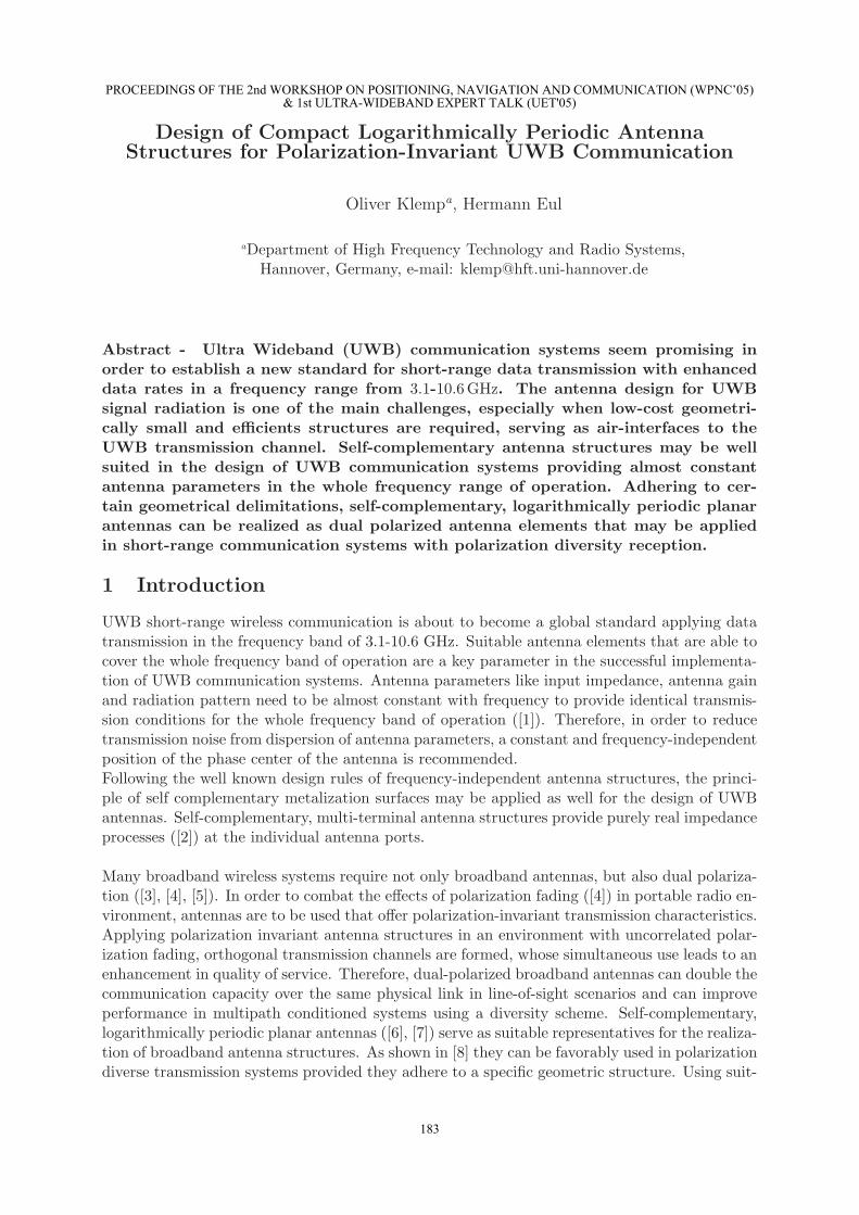
Figure 1: Design process of logarithmically-periodic antenna structures based upon a conformaltransformation between the p- and the q-plane.
Subsequently planar, arbitrarily shaped metalization surfaces with infinite radial extent, an idealelectrical conductance and an infinitesimal geometrical thickness will be considered. Presumedthe regarded geometries merge by exchanging conducting- with isolating surfaces, they pro-vide self-complementary properties. The planar, self-complementary spiral- and logarithmically-periodic antennas are well known representatives to frequency-independent antenna designs ([9]).In terms of the desired polarization diversity reception, spiral antennas are not to be consideredsubsequently. Their distinct direction of rotation clearly assigns to a certain direction of circularpolarization, and therefore is not adequate for the implementation in a polarization diversitytransmission system.In order to obtain compact antenna structures that can be easily integrated into short-rangewireless communication devices, the design is restricted to planar log.-per. antenna structures.Considering the fact that each polarization state in a plane may be decomposed into a system oftwo orthogonal linear polarizations, the design of an antenna structure offering N = 4 antennaarms is an adequate choice. Antenna structures of that kind theoretically provide frequency-independent real input impedances of 133 Ω at the individual antenna ports ([10]).The synthesis of log.-per. antenna structures starts with the choice of an adequate basis geome-try function (so-called unit cell). From the literature e.g. sinusoidal basis functions, rectangular-and triangular basis functions are known ([6], [9]). In general, log.-per. antenna geometries aregiven by means of a conformal transformation between the corresponding basis geometry in theso-called p-plane and the complex q-plane according to:
q = x (v, w) + j y (v, w) = r (v) ej ϕ(v,w) (1)
with r (v) = ev and ϕ (v, w) = w (v) .
PROCEEDINGS OF THE 2nd WORKSHOP ON POSITIONING, NAVIGATION AND COMMUNICATION (WPNC’05)& 1st ULTRA-WIDEBAND EXPERT TALK (UET'05)
184
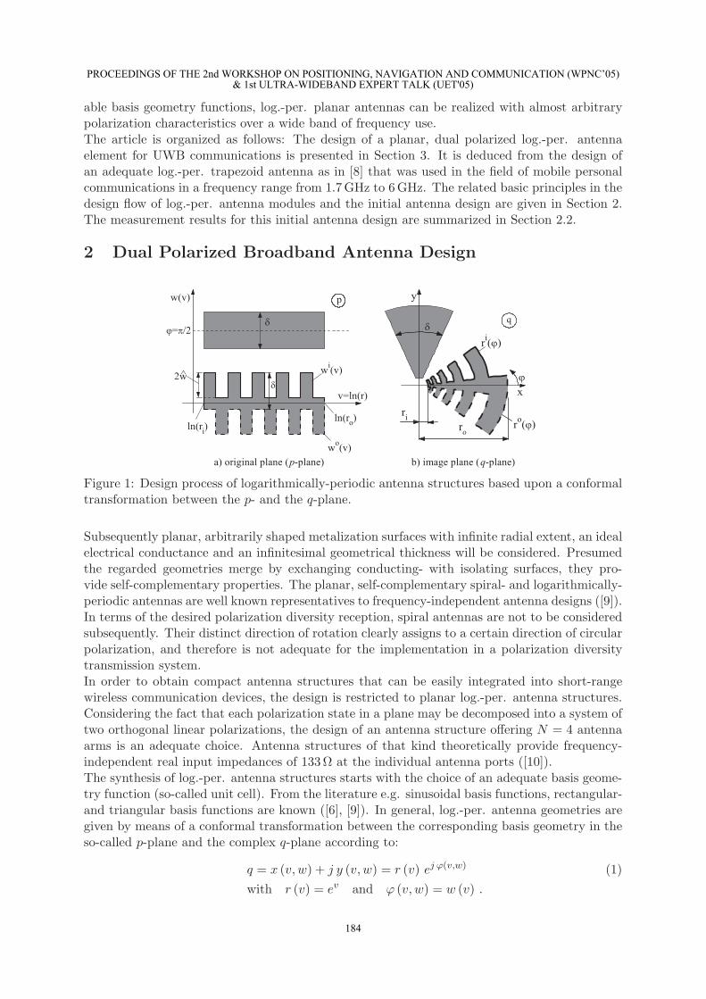
In (1), v and w represent the cartesian coordinates in the p-plane, the complex q-plane is givenin terms of x and y. Therefore, vertical sections of the unit cell are mapped to circular arcsegments, horizontal sections lead to radial lines in the q-plane. Fig. 1 a), depicts two examplesof periodic repetitions of unit cell geometries in the p-plane. The basis geometry functions shownprovide a rectangular shape and a shape with constant amplitude. Applying the transformationgiven in (1), the basis geometry functions are mapped to the geometries in the image planeas shown in Fig. 1 b). δ is the angular spread of one antenna arm. In the radial direction,the antenna arm is delimited by the radii ri and ro. In Fig. 2, the respective symmetricalfour-arm antenna with a rectangular shape is shown. Due to the functional principle of planarlog.-per. antenna structures, each arm can be decomposed into two main operational units: Atapered, radial oriented line that distributes the transmission line power from the feeding pointat the center of the antenna structure to the outer antenna region and azimuthally orientedresonators with different angular lengths lq. Radiation occurs at radius positions rrad, where theeffective electrical lengths of the resonators are equal to a quarter of the operational wavelengthλ ([7]) so that they are able to scatter electromagnetic energy. The theoretical boundariesof a quasi frequency-independent transmission behavior are limited by the azimuthal lengthsof the resonators with the smallest- and with the largest angular lengths lq,min = lq |ri andlq,max = lq |ro .
Figure 2: Symmetrical, log.-per. four-arm antenna structure based upon a rectangular basisgeometry function.
The choice of the unit cell is arbitrary but influences to the cross-polarization decoupling be-tween two orthogonal antenna arm pairs and the lower cut-off frequency. The trapezoidal basisgeometry as reported in [8] was shown to provide the lowest cut-off frequency and the highestdegree of cross-polarization decoupling among the basis geometry functions reported in the lit-erature. In terms of an operation with dual linear polarization, each of the two pairs of adjacentantenna arms is related to a distinct linear polarization state that represents one diversity branchof the polarization diversity system. Therefore, differential voltages are applied at the feedingbridge of adjacent antenna arms. The trapezoid antenna consists of a planar, self-complementary(δ = π/4) four-arm geometry, with M = 5.5 unit cell periods and an amplitude of w = π/4.The percentage slope of the trapezoid is given as ss = 50%. The antenna is extended in a radiusinterval of ri = 5.0 mm and ro = 50.0 mm in free-space.Log.-per. antenna modules adhere to the principle of discrete scaling invariance. Therefore, thequotient of the angular lengths l1 and l2 of the unit cells of two subsequent resonators as shownin Fig. 2 equals to the inverse of the so-called self-similarity factor τ .
PROCEEDINGS OF THE 2nd WORKSHOP ON POSITIONING, NAVIGATION AND COMMUNICATION (WPNC’05)& 1st ULTRA-WIDEBAND EXPERT TALK (UET'05)
185
2.1 Specification of Operational Bandwidth
In practical realizations the frequency-independent impedance behavior of the antenna structureis limited due to the utilization of specialized feed assembly and metalization surfaces with finiteextent. The radial extent of the metalization surfaces is defined by the outer delimitation radiusro and the inner radius limit ri which is determined by coaxial feeds at the center of the antennastructure. Although if the electromagnetically active regions are within the radial delimitationsof the metalization surfaces and therefore offer self-complementary properties, almost constantcharacteristics of the feed impedance in a reduced frequency range of operation can be observed([6]). From there the lower cut-off frequency for the quasi frequency-independent operationalmode of the antenna structure is determined by the outer delimitation radius ro. Generally,the theoretical lower- and upper cut off frequencies fl,c and fu,c of quasi frequency-independentimpedance behavior can be formulated in accordance with [11] as follows:
fl,c =c0
4ro
(δ2 + w
) and fu,c =c0
4ri
(δ2 + w
) . (2)
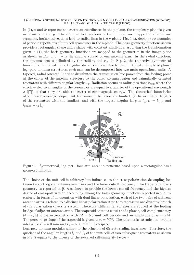
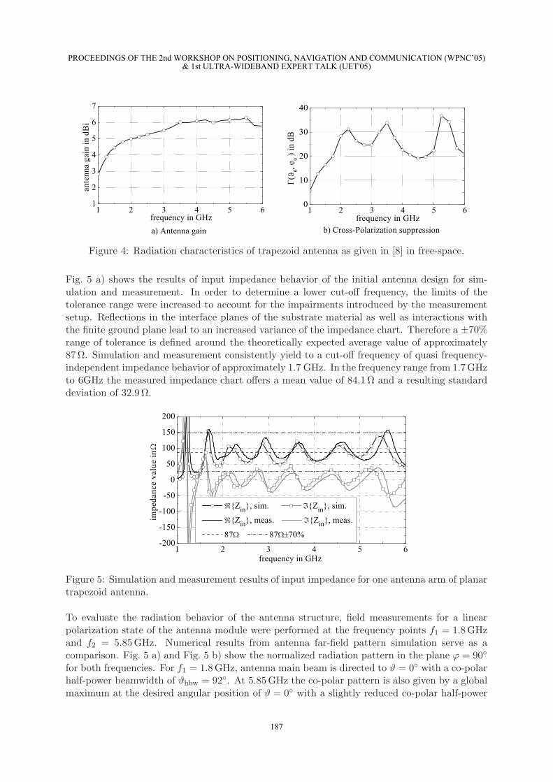
We will address our design restrictions to the definition of a lower cut-off frequency that specifiesthe lower bound of quasi frequency-independent impedance characteristics. Using a ±25% rangeof tolerance around the expected impedance value of 133 Ω which is representative for an idealself complementary four-arm antenna structure in free space, the cut-off frequency is defined bythe lowest frequency as of the impedance process remains in the tolerance range. As given in [8]the cut-off frequency of the trapezoid antenna amounts to fl,c = 1.7 GHz.Subsequently the radiation properties of the planar, log.-per. four-arm trapezoid antenna willbe summarized. Fig. 3 shows the radiated power in case of an excitation with dual linearpolarization in a frequency interval from 1 GHz to 6 GHz. Apart from the lower cut-off frequencyat fl,c = 1.7 GHz, the radiated power remains almost constant to be Prad 8 mW. In terms ofantenna gain as shown in Fig. 4 a), a mean value of 5.7 dBi is observed with a slight variationof about 1.3 dBi in the interesting frequency range. As shown in Fig. 4 b) the cross polarizationsuppression in main beam direction for linear polarization, Γ (ϑ0 = 0, ϕ0 = 0), remains aboveapproximately 20 dB in the entire frequency range of operation.
Figure 3: Radiated power in terms of an excitation with dual linear polarization of the trapezoidantenna as given in [8] in free-space.
2.2 Measurement Results
In order to verify the simulation results for the trapezoid antenna structure, the antenna elementwas developed on microwave substrate (εr = 2.33) and embedded between two substrate layersleading to a reduction of the theoretical impedance values at each antenna port to approximately133Ω/
√εr 87Ω.
PROCEEDINGS OF THE 2nd WORKSHOP ON POSITIONING, NAVIGATION AND COMMUNICATION (WPNC’05)& 1st ULTRA-WIDEBAND EXPERT TALK (UET'05)
186
Figure 4: Radiation characteristics of trapezoid antenna as given in [8] in free-space.
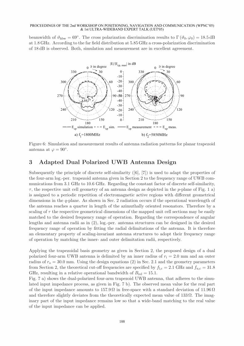
Fig. 5 a) shows the results of input impedance behavior of the initial antenna design for sim-ulation and measurement. In order to determine a lower cut-off frequency, the limits of thetolerance range were increased to account for the impairments introduced by the measurementsetup. Reflections in the interface planes of the substrate material as well as interactions withthe finite ground plane lead to an increased variance of the impedance chart. Therefore a ±70%range of tolerance is defined around the theoretically expected average value of approximately87 Ω. Simulation and measurement consistently yield to a cut-off frequency of quasi frequency-independent impedance behavior of approximately 1.7 GHz. In the frequency range from 1.7 GHzto 6GHz the measured impedance chart offers a mean value of 84.1 Ω and a resulting standarddeviation of 32.9 Ω.
Figure 5: Simulation and measurement results of input impedance for one antenna arm of planartrapezoid antenna.
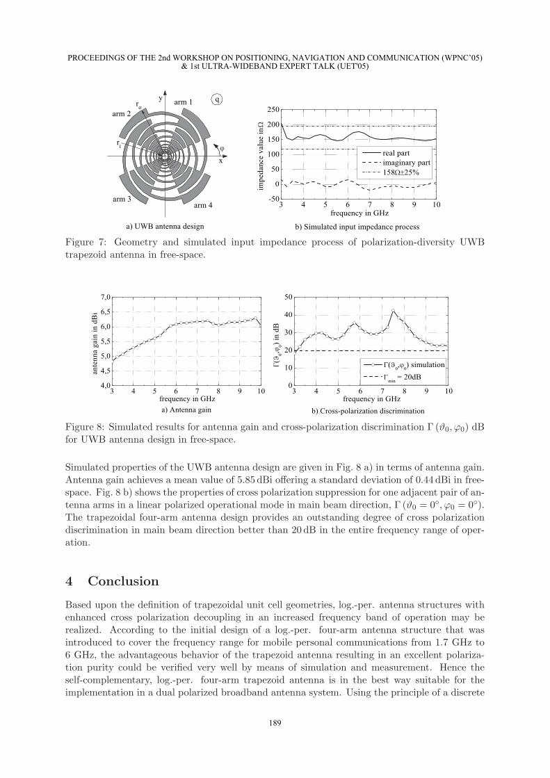
To evaluate the radiation behavior of the antenna structure, field measurements for a linearpolarization state of the antenna module were performed at the frequency points f1 = 1.8 GHzand f2 = 5.85 GHz. Numerical results from antenna far-field pattern simulation serve as acomparison. Fig. 5 a) and Fig. 5 b) show the normalized radiation pattern in the plane ϕ = 90
for both frequencies. For f1 = 1.8 GHz, antenna main beam is directed to ϑ = 0 with a co-polarhalf-power beamwidth of ϑhbw = 92. At 5.85 GHz the co-polar pattern is also given by a globalmaximum at the desired angular position of ϑ = 0 with a slightly reduced co-polar half-power
PROCEEDINGS OF THE 2nd WORKSHOP ON POSITIONING, NAVIGATION AND COMMUNICATION (WPNC’05)& 1st ULTRA-WIDEBAND EXPERT TALK (UET'05)
187
beamwidth of ϑhbw = 69. The cross polarization discrimination results to Γ (ϑ0, ϕ0) = 18.5 dBat 1.8 GHz. According to the far field distribution at 5.85 GHz a cross-polarization discriminationof 18 dB is observed. Both, simulation and measurement are in excellent agreement.
Figure 6: Simulation and measurement results of antenna radiation patterns for planar trapezoidantenna at ϕ = 90.
3 Adapted Dual Polarized UWB Antenna Design
Subsequently the principle of discrete self-similarity ([6], [7]) is used to adapt the properties ofthe four-arm log.-per. trapezoid antenna given in Section 2 to the frequency range of UWB com-munications from 3.1 GHz to 10.6 GHz. Regarding the constant factor of discrete self-similarity,τ , the respective unit cell geometry of an antenna design as depicted in the p-plane of Fig. 1 a)is assigned to a periodic repetition of electromagnetic active regions with different geometricaldimensions in the q-plane. As shown in Sec. 2 radiation occurs if the operational wavelength ofthe antenna reaches a quarter in length of the azimuthally oriented resonators. Therefore by ascaling of τ the respective geometrical dimensions of the mapped unit cell sections may be easilymatched to the desired frequency range of operation. Regarding the correspondence of angularlengths and antenna radii as in (2), log.-per. antenna structures can be designed in the desiredfrequency range of operation by fitting the radial delimitations of the antenna. It is thereforean elementary property of scaling-invariant antenna structures to adopt their frequency rangeof operation by matching the inner- and outer delimitation radii, respectively.
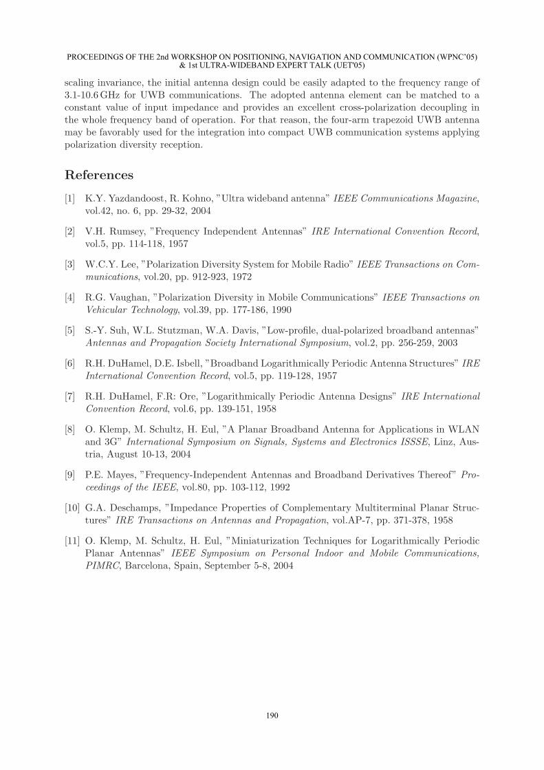
Applying the trapezoidal basis geometry as given in Section 2, the proposed design of a dualpolarized four-arm UWB antenna is delimited by an inner radius of ri = 2.0 mm and an outerradius of ro = 30.0 mm. Using the design equations (2) in Sec. 2.1 and the geometry parametersfrom Section 2, the theoretical cut-off frequencies are specified by fl,c = 2.1 GHz and fu,c = 31.8GHz, resulting in a relative operational bandwidth of Brel = 15.1.Fig. 7 a) shows the dual-polarized four-arm trapezoid UWB antenna, that adheres to the simu-lated input impedance process, as given in Fig. 7 b). The observed mean value for the real partof the input impedance amounts to 157.9 Ω in free-space with a standard deviation of 11.96 Ωand therefore slightly deviates from the theoretically expected mean value of 133 Ω. The imag-inary part of the input impedance remains low so that a wide-band matching to the real valueof the input impedance can be applied.
PROCEEDINGS OF THE 2nd WORKSHOP ON POSITIONING, NAVIGATION AND COMMUNICATION (WPNC’05)& 1st ULTRA-WIDEBAND EXPERT TALK (UET'05)
188
Figure 7: Geometry and simulated input impedance process of polarization-diversity UWBtrapezoid antenna in free-space.
Figure 8: Simulated results for antenna gain and cross-polarization discrimination Γ (ϑ0, ϕ0) dBfor UWB antenna design in free-space.
Simulated properties of the UWB antenna design are given in Fig. 8 a) in terms of antenna gain.Antenna gain achieves a mean value of 5.85 dBi offering a standard deviation of 0.44 dBi in free-space. Fig. 8 b) shows the properties of cross polarization suppression for one adjacent pair of an-tenna arms in a linear polarized operational mode in main beam direction, Γ (ϑ0 = 0, ϕ0 = 0).The trapezoidal four-arm antenna design provides an outstanding degree of cross polarizationdiscrimination in main beam direction better than 20 dB in the entire frequency range of oper-ation.
4 Conclusion
Based upon the definition of trapezoidal unit cell geometries, log.-per. antenna structures withenhanced cross polarization decoupling in an increased frequency band of operation may berealized. According to the initial design of a log.-per. four-arm antenna structure that wasintroduced to cover the frequency range for mobile personal communications from 1.7 GHz to6 GHz, the advantageous behavior of the trapezoid antenna resulting in an excellent polariza-tion purity could be verified very well by means of simulation and measurement. Hence theself-complementary, log.-per. four-arm trapezoid antenna is in the best way suitable for theimplementation in a dual polarized broadband antenna system. Using the principle of a discrete
PROCEEDINGS OF THE 2nd WORKSHOP ON POSITIONING, NAVIGATION AND COMMUNICATION (WPNC’05)& 1st ULTRA-WIDEBAND EXPERT TALK (UET'05)
189
scaling invariance, the initial antenna design could be easily adapted to the frequency range of3.1-10.6 GHz for UWB communications. The adopted antenna element can be matched to aconstant value of input impedance and provides an excellent cross-polarization decoupling inthe whole frequency band of operation. For that reason, the four-arm trapezoid UWB antennamay be favorably used for the integration into compact UWB communication systems applyingpolarization diversity reception.
References
[1] K.Y. Yazdandoost, R. Kohno, ”Ultra wideband antenna” IEEE Communications Magazine,vol.42, no. 6, pp. 29-32, 2004
[2] V.H. Rumsey, ”Frequency Independent Antennas” IRE International Convention Record,vol.5, pp. 114-118, 1957
[3] W.C.Y. Lee, ”Polarization Diversity System for Mobile Radio” IEEE Transactions on Com-
munications, vol.20, pp. 912-923, 1972
[4] R.G. Vaughan, ”Polarization Diversity in Mobile Communications” IEEE Transactions on
Vehicular Technology, vol.39, pp. 177-186, 1990
[5] S.-Y. Suh, W.L. Stutzman, W.A. Davis, ”Low-profile, dual-polarized broadband antennas”Antennas and Propagation Society International Symposium, vol.2, pp. 256-259, 2003
[8] O. Klemp, M. Schultz, H. Eul, ”A Planar Broadband Antenna for Applications in WLANand 3G” International Symposium on Signals, Systems and Electronics ISSSE, Linz, Aus-tria, August 10-13, 2004
[9] P.E. Mayes, ”Frequency-Independent Antennas and Broadband Derivatives Thereof” Pro-
ceedings of the IEEE, vol.80, pp. 103-112, 1992
[10] G.A. Deschamps, ”Impedance Properties of Complementary Multiterminal Planar Struc-tures” IRE Transactions on Antennas and Propagation, vol.AP-7, pp. 371-378, 1958
[11] O. Klemp, M. Schultz, H. Eul, ”Miniaturization Techniques for Logarithmically PeriodicPlanar Antennas” IEEE Symposium on Personal Indoor and Mobile Communications,
PIMRC, Barcelona, Spain, September 5-8, 2004
PROCEEDINGS OF THE 2nd WORKSHOP ON POSITIONING, NAVIGATION AND COMMUNICATION (WPNC’05)& 1st ULTRA-WIDEBAND EXPERT TALK (UET'05)