Page 1
Graduate Theses, Dissertations, and Problem Reports
2016
Design of composite sandwich panels for lightweigh applications Design of composite sandwich panels for lightweigh applications
in air cargo containers in air cargo containers
Mariana M. William
Follow this and additional works at: https://researchrepository.wvu.edu/etd
Recommended Citation Recommended Citation William, Mariana M., "Design of composite sandwich panels for lightweigh applications in air cargo containers" (2016). Graduate Theses, Dissertations, and Problem Reports. 3980. https://researchrepository.wvu.edu/etd/3980
This Problem/Project Report is protected by copyright and/or related rights. It has been brought to you by the The Research Repository @ WVU with permission from the rights-holder(s). You are free to use this Problem/Project Report in any way that is permitted by the copyright and related rights legislation that applies to your use. For other uses you must obtain permission from the rights-holder(s) directly, unless additional rights are indicated by a Creative Commons license in the record and/ or on the work itself. This Problem/Project Report has been accepted for inclusion in WVU Graduate Theses, Dissertations, and Problem Reports collection by an authorized administrator of The Research Repository @ WVU. For more information, please contact [email protected] .
Page 2
Design of Composite Sandwich Panels for
Lightweight Applications in Air Cargo
Containers
Mariana M. William
A Problem Report submitted to
The Benjamin Statler College of Engineering and Mineral Resources West Virginia University
in partial fulfillment of the requirements for the degree of
Masters of Sciences
in
Mechanical Engineering
Samir N. Shoukry, Ph.D., Chair Jacky C. Prucz, Ph.D.
Kenneth H. Means, Ph.D.
Department of Mechanical and Aerospace Engineering Morgantown, WV
November 2016
Keywords: Design of Composite Sandwich Panels, Air Cargo Containers, Lightweight Technologies, Sandwich Panels, Composite Materials.
Page 3
ABSTRACT
Design of Composite Sandwich Panels for Lightweight Applications
in Air Cargo Containers
Mariana M. William
Air cargo containers are used to load freight on various types of aircrafts to
expedite their handling. The current containers are closed containers made of
aluminum or combination of aluminum (frame) and Lexan (walls). The objective of
this study is to develop innovative, lightweight design and joining concepts for air
cargo containers that would allow for weight reduction in the air cargo transportation
industry. For this purpose, lightweight carbon fiber woven composite design
configuration of a typical air cargo container was developed and manufactured. The
new design was devised to meet the FAA-approved certification requirements of the
Technical Standard Order TSO-C90, Cargo Pallets, Nets, and Containers. The
manufactured model was used to evaluate the technical feasibility and economic
viability of creating such a container from fiber-reinforced polymer (FRP) composite
materials. The model was also used to assess the need for the development of suitable
and innovative joining techniques that could be used in building such containers and
estimate the expected weight reduction.
The new design is expected to lower the structural weight of the LD-3 cargo
containers from 76 kg for a typical aluminum container to about 20 kg, which
represents a weight reduction of 75 percent. This weight reduction would achieve
significant savings in fuel cost that would recover the increase in the cost of building
such containers.
Page 4
iii
ACKNOWLEDGEMENTS
It is almost impossible to complete this long journey without the support from my
family and friends. First, I would like to thank my parents for their encouragement
and support over the years and my husband for his understanding and love during the
hardest period in my life.
I would like to express my deepest gratitude and respect for my advisor,
Professor Samir Shoukry, for supporting my research and helping me find an area of
intellectual pursuit that fit my abilities and interests well. His endless contribution of
ideas and insights resulted in bettering my efforts to design the air cargo containers.
Having learned under his tutelage helped me to grow both intellectually and as a
person.
I would like to thank Dr. Jacky Prucz for all his help in my study. Many thanks
are owed to Dr. Ken Means for serving on my examining committee. Special thanks
also extended to Ms. Susan Dess, Manager of Engineering Support Center at
American Airlines, for her assistance and advice during the composite manufacturing
and prototyping of the air cargo container.
Page 5
iv
TABLE OF CONTENTS ABSTRACT ............................................................................................................................................... II
ACKNOWLEDGEMENTS ................................................................................................................... III
TABLE OF CONTENTS ........................................................................................................................ IV
LIST OF TABLES ..................................................................................................................................... V
LIST OF FIGURES ................................................................................................................................ VI
CHAPTER 1 INTRODUCTION ............................................................................................................. 1
1.1 BACKGROUND .................................................................................................................................... 1
1.2 UNIT LOAD DEVICES .......................................................................................................................... 2
1.3 COMPOSITE UNIT LOAD DEVICES ...................................................................................................... 5
1.4 RESEARCH OBJECTIVES ...................................................................................................................... 5
CHAPTER 2 LITERATURE REVIEW ................................................................................................. 7
2.1 INTRODUCTION ................................................................................................................................... 7
2.2 SANDWICH COMPOSITES .................................................................................................................... 7
2.2.1 Core ............................................................................................................................................ 8
2.2.1.1 Honeycomb Core ............................................................................................................................... 11
2.3 FACE MATERIALS ............................................................................................................................. 12
CHAPTER 3 UNIT LOAD DEVICE DESIGN .................................................................................... 16
3.1 INTRODUCTION ................................................................................................................................. 16
3.2 DESIGN REQUIREMENTS ................................................................................................................... 16
3.2.1 Base Performance .................................................................................................................... 17
3.3 THEORETICAL MODEL ...................................................................................................................... 18
3.4 FAILURE MODES FOR HONEYCOMB SANDWICH STRUCTURES......................................................... 25
3.4.1 Failure Modes in the Skin ........................................................................................................ 25
3.4.2 Core Failure ............................................................................................................................. 27
3.5 LIGHTWEIGHT DESIGN OF LD-3 BASE ............................................................................................. 28
CHAPTER 4 PROTOTYPING OF LIGHTWEIGHT ULD .............................................................. 34
4.1 INTRODUCTION ................................................................................................................................. 34
4.1.1 Hand Lay-up ............................................................................................................................. 34
4.1.2 Bag Molding ............................................................................................................................. 35
4.2 PROTOTYPING ................................................................................................................................... 36
CHAPTER 5 SUMMARY AND CONCLUSIONS .............................................................................. 40
REFERENCES ......................................................................................................................................... 41
Page 6
v
LIST OF TABLES TABLE 1.1 Weights and Volumes of Current LD-3 Containers ............................. 4 TABLE 2.1 Honeycomb Sandwich Efficiency ..................................................... 11 TABLE 2.2 Comparison between Honeycomb and Foam Cores (Bitzer 1997) ... 12 TABLE 3.1 Ultimate Load Criteria for LD-3 ....................................................... 17 TABLE 3.2 Numerical Factors α, β, γ, δ, n for Uniformly Loaded and Simply
Supported Rectangular Plates (ν = 0.3) ............................................ 24 TABLE 3.3 Properties of Nomex Honeycomb Core ............................................ 29
Page 7
vi
LIST OF FIGURES Figure 1.1 ULD Cargo Containers in Airbus A300 (Wikipedia, 2014) .................. 3 Figure 1.2 Unit Load Device LD-3 ......................................................................... 3 Figure 2.1 Types of Sandwich Panel Cores (Petras 1998). ..................................... 9 Figure 2.2 Cross Section of Monococque and Sandwich Construction. .............. 10 Figure 2.3 Specific Stiffness and Specific Strength for Various Materials ........... 14 Figure 3.1 Internal Forces on the Plate ................................................................. 18 Figure 3.2 Coordinate System of the plate. .......................................................... 21 Figure 3.3 Face Yielding ....................................................................................... 25 Figure 3.4 Intra-Cell Dimpling ............................................................................. 26 Figure 3.5 Face Wrinkling .................................................................................... 26 Figure 3.6 Core Shear Failure ............................................................................... 27 Figure 3.7 Cure Crushing Failure ......................................................................... 28 Figure 3.8 Nomex Honeycomb Core HD-1/8-1.8 ................................................ 29 Figure 4.1 Nomex Honeycomb Core Used in Prototyping ................................... 36 Figure 4.2 Finished Composite Sandwich Panel for ULD Base ........................... 37 Figure 4.3 Side Walls of the Air Cargo Container ................................................. 38 Figure 4.4 Full Scaled Model of Air Cargo Container .......................................... 38 Figure 4.5 Clip Joint for Attaching Side Walls ...................................................... 39
Page 8
1
Chapter 1
Introduction
1.1 Background
The role of air transport in providing rapid and intercontinental connections has
made it an essential economic and social conduit throughout the world. In 2010, the
air transport industry transported approximately 43.3 million tons of freight
worldwide, up from 30.4 million in 2000, which account for nearly 40 percent of all
goods by value. Many developing countries today depend heavily on air cargo for
their exports as other modes of transportation are unreliable or non-existent (The
World Bank, 2012). This demonstrates clearly that the air transport sector is
undergoing an optimistic growth rate while at the same time eliciting growing concern,
due to its environmental impact and its vulnerability with respect to energy security.
These issues have put the sector at the forefront of the tide in achieving energy
efficiency. Efforts have been made on every front to improve efficiency through better
technology, optimized operation, as well as energy-saving infrastructure.
According to the International Energy Agency (IEA), aviation used 246 million
tons of oil equivalents (Mtoe) of energy in 2006, which represented 11 percent of all
transport energy used. Aviation’s energy usage is expected to triple to about 750 Mtoe
by 2050, according to the IEA’s baseline scenario; as a result, aviation would account
for 19 percent of all energy used (IEA 2009). The growing demand in energy along
with rising fuel costs is endangering the air transport’s optimistic growth.
Traditionally, fuel costs were less than 15 percent of airline operational costs; however,
they have risen substantially since 2003. Fuel costs rose to around 33 percent in 2008
and exceeded 40 percent for carriers with lower labor costs (IATA 2009). However,
some studies suggest that aviation overall warming impact is much higher given its
emissions of the greenhouse gases such as NOx, CH4, and H2O among others, as well
as differential effects of emissions at different altitudes.
With a growing sense of urgency for sustainability actions among consumers and
governments around the world, air transport industry is under pressure to operate in
Page 9
2
sustainable manners (Brown 2009). Freight transportation is a large and fast growing
contributor of GHG emissions, especially carbon dioxide (CO2) that accounts for
more than 90 percent of GHGs (Varma and Clayton 2010). Aviation causes about 2
percent of total man-made carbon emissions according to the Intergovernmental Panel
on Climate Change (IPCC). Aviation emitted about 810 million tons of CO2 in 2006,
which represents about 12 percent of all transport CO2 emissions (IATA 2009). The
industry is growing by around 5% a year in the longer term but efficiencies already in
place mean aviation CO2 emissions are growing by just 2 to 3 percent. Therefore, it is
vital to develop new technologies in to reduce the overall emissions. This could be
best achieved by lowering fuel consumption through enhancing aviation efficiencies.
Lightweighting aircraft and freight transport hardware by using new materials
and composites was envisioned as a means that can significantly improve fuel
efficiency and reduce greenhouse gas emission. This significant weight reduction will
also result in an improved payload, and reduce the freight cost.
1.2 Unit Load Devices
A unit load device (ULD) is a pallet or container used to load luggage, freight,
and mail on an aircraft. It allows a large quantity of cargo to be bundled into a single
unit, thus leads to fewer units to load. As a result, it saves ground crews time and
effort and helps prevent delayed flights. Because of regulatory requirements as well as
practical considerations, the shape, size and maximum weight of a ULD for each type
of aircraft have been standardized.
Typically, ULDs are shaped as boxes, which can include sloped surfaces, which
conform the ULD to the aircraft’s fuselage when the ULD is placed in the cargo
compartment as shown in Figure 1.1. The container is made of several panels that are
joined together to form the ULD and define an enclose storage volume. The ULD is
often constructed from a metal such as aluminum or one of its alloys that are able to
tolerate the tough handling conditions the container experiences through transfer and
transport situations.
Page 10
3
ULDs are built in several shapes and types to be compatible with different
aircrafts. This study will focus on LD-3, shown in Figure 1.2, as a case study
keeping in mind that any new lightweight design that will be developed could be
extended and applied to any other ULD types.
Figure 1.2 Unit Load Device LD-3
Figure 1.1 ULD Cargo Containers in Airbus A300 (Wikipedia, 2014)
Page 11
4
TABLE 1.1 Weights and Volumes of Current LD-3 Containers
Company Internal Volume Maximum
Gross Weight Tare Weight
(Approx.) with Net Country 3ft
3m lb kg lb kg FedEx (AVE/LD-3)
153 4.3 3,500 1,588 215 98
Profreight (LD-3)
150 4 3,500 1,588
Nippon Cargo Airlines
153 4.3 3,500 1,588 198-231 90-105
Grange Aerospace AKE
150 4 3,500 1,588 187 85
Shapiro AKE
152 4.3 3,500 1,588
Cathay Pacific Cargo AKE
152 4.3 3,500 1,588 73-100
Boeing 159 4.5 3,500 1,588 181 82
DSV Global Transport and Logistics
3,500 1,587 181 82
Emirates Sky Cargo 152 4.3 3,500 1,587 66 Emirates
Air New Zealand 153 4.3 3,500 1,587 187 85 New Zealand
Royal Jordanian Cargo
3.8 3,500 1,588 85
Quantum Transportation LTD.
150 4.2 3,493 1,588 158 72
Atlas Logistics 152 4.3 3,500 1,588 100 India
Sea Rates 159 4.5 3,500 1,588 181 82 England
Air China Cargo 152 4.3 3,500 1,588 73-100 China
ANA Cargo 156 4.4 3,500 1,587 157 71 China
VRR Aviation 3,500 1,588 >152 >69
Dragonair Cargo 152 4.3 3,500 1,588 100
Turkish International Forwarding & Logistic Services
150 4.2 3,493 1,588 158 72 Turkish
TKM Global 150 4.2 3,493 1,588 158 72 Germany
Tetra Logistics 152 4.3 3,500 1,588 100
Air Fast Freight System
4.3 3,500 1,587 90-105 China
Chep 4.3 3,500 1,588 82
Egyptair 160 4.53 3,500 1,588 154 70 Egypt
Page 12
5
The LD-3 provides a volumetric capacity of 4.50 m3 (159 cubic foot). Currently,
there are multiple manufacturers for this LD-3. Although the outside dimensions for
the units produced by different manufacturers are the same, the inside volume and tare
weight of the unit differ among manufactures as shown in Table 1.1.
The performance requirements and test parameters for airworthiness approval of
a unit load device determine the ultimate load capabilities under defined restraint
conditions. The ULD ultimate load is defined as the maximum expected limit load
multiplied by a factor of safety of 1.5. For a typical LD-3 container shown in Figure
1.2, the maximum gross weight is 15,567 N (3,500 lbs) and its ultimate load is 23,350
N (5,250 lbs). The current tare weight of this aluminum container is 805 N (181 lbs)
1.3 Composite Unit Load Devices
The new trend in the industry is to replace traditional all-aluminum or
semi-composite ULDs with new lightweight, all-composite ULDs. Caro Composites
produced new line of products named “AeroBox” whose upper structure is made of
all-composite materials. The tare weight of this container is 58 kg (128 lb) that
includes a 2.5 mm thick 7075-T6 aluminum base (Cargo Composites 2016).
The composite panels that form the body of the container are comprised of two
tough, fiberglass/polypropylene composite skins thermo-fused to a resilient
polypropylene honeycomb core. This combination of materials absorbs high impacts
and evenly deflects forces across the panels, reducing damage and significantly
increasing uptime. The edges of the panels are joined to the sides of the container
using industry standard lock bolts. This eliminates the traditional damage-prone post
and beam framework/superstructure that is used in both aluminum and
semi-composite ULDs.
1.4 Research Objectives
The main objective of this study is to create design and joining methods that
will allow the incorporation of lightweight composite plates, panels or structures
into a ULD container design. Innovative joining methods will create solutions to
Page 13
6
connect components in ULD container, in place of mechanical joints, which include
bolting and riveting.
Page 14
7
Chapter 2
Literature Review
2.1 Introduction
This chapter presents a review of the current and emerging technologies that
could be adopted and integrated in order to reduce the structural weight of air cargo
containers, hence improve fuel efficiency and reduce environmental impacts.
Advanced composites have become an attractive design alternative for a wide range
of industrial applications due to their excellent mechanical properties such as high
strength-to-weight ratio, impact and fatigue properties. Such unique properties of
composites promise a variety of applications ranging from lightweight construction,
impact energy absorption and thermal insulation.
2.2 Sandwich Composites
The principle of the sandwich panel has been put to effective use for many years
before it was defined by engineers and recognized as a separate type of construction
dominated by certain mathematical principles (Vinson 1999). The sandwich concept
was first recognized during the accelerated search for high-strength, lightweight
materials for aircraft in World War II (Seidl 1956). Sandwich panels are comprised of
two face sheets or top and bottom layers with a core material placed or “sandwiched”
between. This type of arrangement creates a light and stiff structure, because the
stiff faces are distanced from the neutral axis, similar to the flanges of an I-beam. The
facings are made of high-strength material, such as steel, and composites such as
graphite/epoxy while the core is made of thick and lightweight materials such as foam,
cardboard or plywood (Kaw 2006). The faces carry the majority of the axial loading
and transverse bending stress (Hexell Composites 2000). The core resists the shear
loads, increases the stiffness of the structure by holding the facing skins apart, and
improving on the I-beam, it gives continuous support to the flanges or facing skins to
produce a uniformly stiffened panel. Thus, it serves to stabilize the faces against
buckling and carries most of the shear forces (Nicholls 1976). The core-to-skin
Page 15
8
adhesive rigidly joins the sandwich components and allows them to act as one unit
with a high torsional and bending rigidity. When specific tailoring of a sandwich
composite is required, the top and bottom face sheets may differ in material and
thickness. A change of this nature would aide a sandwich composite that needs
temperature resistance on one side more than the opposing side or perhaps one side
will primarily carry an impact load or static deflection.
2.2.1 Core
The purpose of the core is to increase the flexural stiffness of the panel. The core
should have a low density in order to add as little as possible to the total weight of the
panel. However, it must have enough stiffness in shear and perpendicular to provide
spacing between the face sheets. Additionally, the core must withstand compressive
loads without failure (Mukundan 2003). In sandwich composite design, there are no
limitations as to what material can be used as a core structure. Development of new
core materials is a primary interest in sandwich composite design and has evolved
tremendously over the years. Materials used for cores include polymers, aluminum,
wood, papers, and composites. To minimize weight, these materials could be used in
various structural forms, which could be classified into four main categories: (a) foam,
(b) honeycomb, (c) corrugated, and (d) web as seen in Figure 2.1.
The sandwich structures shown in Figure 2.1 have variations and different
attributes for each type of core material. Foam or solid cores, shown in Figure 2.1 (a),
are relatively inexpensive and can consist of balsa wood, and infinite selection of
foam or plastic materials with a wide range of densities and shear moduli.
Honeycomb-core architecture, Figure 2.1 (b), have been widely used since 1940s. The
two most common types are the hexagonally-shaped cell structure, also known as
Hexcel, and the square cell, also known as egg-crate (Hex. Web core, Figure 2.1 (d)
and corrugated core shown in Figure 2.1 (c) are analogous to set of I-beams or
Z-sections with their flanges connected together. In both design, the space in the core
could be utilized for liquid storage or as a heat exchanger.
In all cases, the primary loading, both in-plane and bending, are carried by the
faces, while the core resists transverse shear loads. It is acceptable to assume that in
foam and honeycomb core sandwich composites all the in-plane and bending loads
Page 16
9
are carried by the faces only. In web-core and corrugated-core structures the core
carries some of the in-plane and bending loads (Vinson 1999).
The increase in flexural stiffness from a monocoque construction to a sandwich
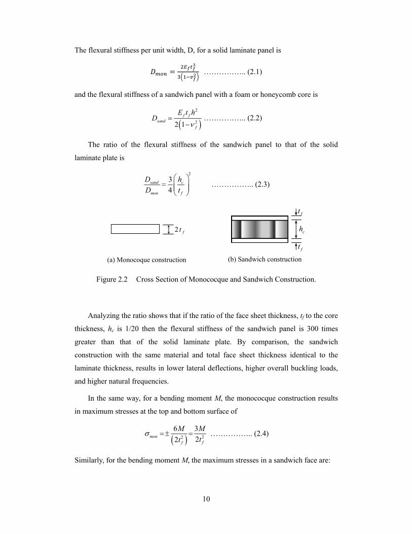
composite can be shown mathematically. Figure 2.2 (a) shows a sandwich
construction that employs two identical isotropic face plates of thickness tf, and a core
thickness of hc. Figure 2.2 (b) shows a sheet monocoque construction of thickness 2 tf.
Figure 2.1 Types of Sandwich Panel Cores (Petras 1998).
(a) Foam core
(b) Honeycomb core
(c) Corrugated core
(d) Web core
Page 17
10
The flexural stiffness per unit width, D, for a solid laminate panel is
…………….. (2.1)
and the flexural stiffness of a sandwich panel with a foam or honeycomb core is
2
22 1f f
sand
f
E t hD
…………….. (2.2)
The ratio of the flexural stiffness of the sandwich panel to that of the solid
laminate plate is
2
3
4sand c
mon f
D h
D t
…………….. (2.3)
Analyzing the ratio shows that if the ratio of the face sheet thickness, tf to the core
thickness, hc is 1/20 then the flexural stiffness of the sandwich panel is 300 times
greater than that of the solid laminate plate. By comparison, the sandwich
construction with the same material and total face sheet thickness identical to the
laminate thickness, results in lower lateral deflections, higher overall buckling loads,
and higher natural frequencies.
In the same way, for a bending moment M, the monococque construction results
in maximum stresses at the top and bottom surface of
22
6 3
22mon
ff
M M
tt …………….. (2.4)
Similarly, for the bending moment M, the maximum stresses in a sandwich face are:
ft
ft
ch2 ft
(a) Monocoque construction (b) Sandwich construction
Figure 2.2 Cross Section of Monococque and Sandwich Construction.
Page 18
11
sand
c f f
M
h t t
…………….. (2.5)
Therefore, the ratio of the bending stress in a sandwich face to the maximum stress in
a monocoque structure of approximately the weight is:
2
3fsand
mon c f
t
h t
…….……… (2.6)
For the example of a sandwich in which tf/hc = 1/20, the bending stress in the
sandwich structure is 2/63 that of moncoque construction. This means the sandwich
structure has a flexural capacity as 31.5 times as that of a monocoque construction of
approximately same weight.
2.2.1.1 Honeycomb Core
The main reason for using honeycomb core is to save weight. However, besides
the weight saving, honeycomb offers other advantages that supersede other types of
cores including high-stiffness-to weight ratio, smooth skins and excellent fatigue
resistance (Bitzer1997, Schwingshackl et al. 2006). If the web spacing is large in
either web and corrugated cores, the skins can deform under applied loads causing a
wavy surface. However, due to the small size of cells of honeycomb core, the skins
retain smooth surface under load (Bitzer 1996).
TABLE 2.1 Honeycomb Sandwich Efficiency
Relative Stiffness 1 7 37 Deflection (in.) 1.000 0.140 0.027 Relative bending strength
1 3.5 11.5
Weight (psf) 0.910 0.978 0.994
In order to demonstrate the potential weight saving, Table 2.1 compares the
strength and stiffness values of different honeycomb structures made using a 0.064 in.
(1.6 mm) thick piece of aluminum split in half as the top and bottom facing of the
sandwich. Using Equations 2.1 through 2.6, the results in Table 2.1 illustrate that
2 ft 4 ft
Page 19
12
while the weight of the sandwich panel increased by 9 percent more than the original
solid plate, its flexural stiffness and strength increased by 37 and 11.5 times
respectively.
Foam core is another foam material that competes with honeycomb. Table 2.2
compares the properties of these core materials as reported by Bitzer (1996). The
honeycomb strengths and shear moduli are considerably higher. Therefore,
honeycomb core is the most optimum lighweighting alternative when core mechanical
properties govern the sandwich design. Foam could be better used in lightly loaded
panels and in insulating panels. However, honeycomb could be also used in the later
situation by filling the cell with foam or another insulating material, which provides a
good structural panel with fair insulating properties.
TABLE 2.2 Comparison between Honeycomb and Foam Cores (Bitzer 1997)
Material
Compression Tensile
Density (pcf)
Strength (psi)
Modulus (ksi)
Strength (psi)
Modulus (ksi)
Aluminum honeycomb 3.1 300 75 210 45 Nomex honeycomb 3.0 325 20 175 6 Fiberglass honeycomb 3.0 410 23 195 19 Rohacell foam 3.1 128 10 114 3 Klegecell foam 3.0 69 2.7 51 1.1 Rigicell foam 3.0 80 2.5 70 2.5 Divinycell foam 3.1 100 10.2 73 2.5
2.3 Face Materials
The faces of a sandwich panel can be comprised of almost any material that is
available in a thin sheet. This sole requirement allows many material options for the
designer to utilize in sandwich panel construction. As described by Zenkert (1997),
the parameters that are of primary concern for developing a structurally sound
sandwich panel are
High stiffness resulting in flexural rigidity
Page 20
13
High compressive and tensile strength
Impact resistance
Aesthetics
Chemical and environmental resistance
Wear resistance
The properties listed can be met by two different categories of face materials,
metallic and non-metallic. Metallic face materials are most commonly sheet metals
because of their geometry and applicability to a sandwich composite design. The
advantages to using a metallic face sheet are low cost, good strength and stiffness, and
high impact properties.
Non-metallic face materials are defined by fiber reinforced polymers (FRP). FRP
are composed of fibers and matrix that define the traditional composite material.
Typical fibers are glass, aramid, and carbon. These fibers are combined with a matrix
by one of the manufacturing methods previously discussed to form an FRP composite.
Orienting the fibers in the direction of applied loads utilizes their high stiffness and
strength properties and tailors the composite laminate to resist and sustain loads.
Having the ability to directionally tailor the stiffness and strength of a composite
allows for reduction of material in directions that do not experience loads, this
ultimately reduces the material being used (cost) and weight.
Lightweight, high strength and stiffness composite materials have been envisioned
as a key cross-cutting technology for reinventing energy efficient transportation,
providing new mechanisms for storing and transporting reduced carbon fuels, and
increasing renewable power production (TMS Energy 2012). Fiber reinforced
polymer composites can be used in vehicles, industrial equipment, wind turbines,
compressed gas storage, buildings and infrastructure, and many other applications.
One industry analysis predicts the global carbon fiber polymer composite market
alone to grow to $25.2 billion in 2020 (Industry Experts 2013) and glass fiber
reinforcements to reach a value of $16.4 billion by 2016 (Industry Experts 2012).
Fiber reinforced polymer composite materials have traditionally been used in
defense, aerospace and other high value, low volume applications where higher costs
and longer production cycle times can be tolerated because of the high performance
Page 21
14
design requirements and resulting high value add of composites in the end-use
products (National Research Council 2005). Improvements to materials and
manufacturing techniques have led to increased use of fiber reinforced polymer
composites in other industries such as sports equipment. However, they have not yet
surpassed the tipping point to meet production volumes and cost targets to support
widespread adoption in various industrial applications, where the application of
composite materials might have significant impact in energy sectors. The energy
intensity of carbon fiber composites and the lack of recyclability for fiber reinforced
polymer composites are further limitations to the use of these materials.
Figure 2.3 Specific Stiffness and Specific Strength for Various Materials (University of Cambridge 2002).
Page 22
15
Fiber reinforced polymer composites (GFRP and CFRP) have superior strength
and stiffness to density ratios relative to other materials as shown in Figure 2.3.
Carbon fiber reinforced polymer (CFRP) composites offer the highest structural
properties to density ratios (specific strength is axial tensile strength divided by
density and specific stiffness is axial modulus divided by density), excellent corrosion
resistance and other desirable properties but are costly relative to other materials on a
weight basis. Glass fiber reinforced polymer composites (GFRP) have improved
specific mechanical properties over metals and cost less than carbon fiber composites
but have lower strength to weight ratio and are not as stiff as carbon fiber composites.
Table 2.3 provides further data for GFRP, CFRP and common metals including
estimated embodied energy and production costs.
The use of composite materials and structures can lead to significant life-cycle
energy benefits by reducing oil consumption in transportation.
Page 23
16
Chapter 3
Unit Load Device Design
3.1 Introduction
Unit Load Devices (ULDs) and other airplane cargo restraint devices are
composed of two general categories, primary and supplemental. An air carrier should
have procedures to control the airworthiness and subsequent operational serviceability
of ULDs and other restraint devices whether used as a primary or a supplemental
restraint.
In the United States, ULDs should meet the requirements of Technical Standard
Order TSO-C90, Cargo Pallets, Nets, and Containers; or other FAA-approved
certification requirements. ULDs that are designed and manufactured to meet the
aforementioned requirements are called “Certified ULDs”. Containers that are
designed to meet different design criteria are considered “Uncertified ULDs”. These
design criteria may be industry standards such as Society of Automotive Engineers
(SAE) Aerospace Standard (AS) 1677, General Requirements for Uncertified
Cargo/Baggage Containers; International Standards Organization (ISO) Publication
No. 4118, Non-certified Lower-deck Containers for Air Transport; International Air
Transport Association (IATA) ULD Technical Manual (UTM) 50; or other
FAA-accepted standard.
3.2 Design Requirements
SAE AIR36106A (SAE 2014) provides a process to determine the performance
requirements and test parameters for airworthiness approval of a unit load device.
This process determines the ultimate load capabilities under defined restraint
conditions, for airworthiness approval under a ULD configuration of Technical
Standard Order TSO C90. This process is independent from the aircraft type that will
carry the unit load device. For example, The LD3 container is designed to meet
TSO-C90c and NAS-3610 revision 10 (type 2K2C) load requirements and has a
Page 24
17
maximum gross weight of 3,500 lbs. The actual gross weight limits for this container,
in a given airplane, are determined in compliance with FAR 25 and listed in the
Approved Weights and Balance Manual for that airplane. TABLE 3.1 shows the
ultimate load criteria for the LD3 Container.
TABLE 3.1 Ultimate Load Criteria for LD-3
Ultimate Load N (lb) CG height mm (in)
CG eccentricity %
Forward Aft Side Up Down Maximum Long. Lateral
23,350 (5,250)
23,350 (5,250)
23,350 (5,250)
43,600 (9,800)
79,400 (17,850)
864 (34)
±10 ±10
The ULD ultimate load is defined as the maximum expected limit load multiplied
by a factor of safety of 1.5. Conversely, since a ULD is tested only to ultimate load,
the maximum limit load it is approved for in a given direction is the UC Table's
ultimate load divided by 1.5.
The specified ultimate loads should be applied with the maximum specified
Centre of Gravity (CG) height and horizontal eccentricities. The specified CG height
was determined in accordance with the worst case for a given base size, i.e., 864 mm
(34 in) for base sizes capable of lower deck carriage [1625 mm (64 in) contour height]
only and 1218 mm (48 in) for base sizes capable of main deck carriage [2438 mm (96
in) or more height]. Where a container's contour or a net's size allows only a lower
load height, the testing CG height may be reduced to 55% of the maximum height of
the container or net contour.
3.2.1 Base Performance
Unit load devices are designed to have a minimum area load capacity of 10 kPa
(209 lb/ft2). The base edges shall have a minimum vertical stiffness EI value of 5×10⁷
N.cm2 (1.75×10⁶ lb.in2).
Page 25
18
3.3 Theoretical Model
The distribution of the internal forces in a plate subjected to lateral loading under
different edge support conditions is dealt with in different textbooks (Timoshenko
1959; Ventsel and Krauthammer 2001).
For a rectangular plate subjected to a distributed load, p and having any boundary
conditions, the internal forces and stresses in any direction can be obtained
mathematically according to the following assumptions and basic equations.
2 2
2 2x
w wM D
x y
………………………………… (3.1)
2 2
2 2y
w wM D
y x
………………………………… (3.2)
2
21xy yx
wM M D
x y
………………………………… (3.3)
Figure 3.1 Internal Forces on the Plate
Page 26
19
3 3
3 2
xyxx
MM w wQ D
x y x x y
………………………… (3.4)
………………………… (3.5)
The above equations give the values of the bending moments, torsional moments,
and the shearing forces, shown in Figure 3.1, at any section of the plate in terms of the
deflection, w.
The load p may be assumed as a sum of distributed loads in the two directions x and y
so that:
xp = part of the load transmitted in the direction of the x-axis.
yp = part of the load transmitted in the direction of the y-axis.
x yp p p ………………………… (3.6)
Knowing that
0yxQQ
px y
………………………… (3.7)
Equations 3.6 and 3.7 can be identical if :
xx
Qp
x
and y
y
Qp
y
Substituting for xQ and yQ from Equations 3.4 and 3.5 yields that:
4 4
4 2 2x
w wp D
x x y
………………………… (3.8)
and
4 4
4 2 2y
w wp D
y x y
………………………… (3.9)
Adding these two equations:
3 3
3 2
y xyy
M M w wQ D
y x y x y
Page 27
20
4 4 4
4 2 2 42
w w w p
x x y y D
………………………… (3.10)
Which gives the differential equation of the elastic surface of a plate loaded
perpendicular to its plane.
In applying this method to uniformly loaded and simply supported rectangular
plates, a further simplification can be made by taking the solution of Equation 3.10 in
the form
1 2w w w ………………………… (3.11)
And assuming w1 in the form of
4 31 2
24
pw x ax a x
D ………………………… (3.12)
Where 1w represents the deflection of a uniformly loaded strip parallel to the x-axis.
The expression in Equation 3.12 satisfies Equation 3.10 as well as the boundary
conditions at the edges x = 0 and x = a.
The expression 2w evidently has to satisfy the equation
4 4 4
2 2 24 2 2 4
2 0w w w
x x y y
………………………… (3.13)
and must be chosen in such a manner as to make the sum of Equation 3.11 satisfy all
boundary conditions of the plate. Taking
21
sinmm
m xw Y
a
………………………… (3.14)
in which, from symmetry, m = 1, 3, 5,……. and substituting it into Equation 3.13, we
obtain
2 2 4 4
/ /2 4
1
2 sin 0IVm m m
m
m m m xY Y Y
a a a
…………… (3.15)
This equation can be satisfied for all values of x only if the function mY satisfies the
equation
2 2 4 4/ /
2 42 0IV
m m m
m mY Y Y
a a
…………… (3.16)
Page 28
21
The integral form of this equation can take the form:
4
cosh sinhm m m
pa m y m y m yY A B
D a a a
sinh coshm m
m y m y m yC D
a a a
…………… (3.17)
Since the deflection surface of the plate is symmetrical with respect to the x-axis
as depicted in Figure 3.2, the expression should be only even functions of y. Thus, the
integration constants Cm = Dm = 0.
The deflection surface is then represented by the following expression
4
4 32 cosh sinh sin24 m m
p pa m y m y m y m xw x ax a x A B
D D a a a a
…………… (3.18)
Which satisfies Equation 3.10 and also the boundary conditions at the sides x = 0 and
x
b/2
b/2
a
y
Figure 3.2 Coordinate System of the plate.
Page 29
22
x = a. The integration constants Am and Bm can be obtained by satisfying the
boundary conditions at the sides y = ± b/2:
2
20 and 0
ww
y
…………… (3.19)
The deflection surface takes the form
4
5 51
4cosh sinh sinm m
m
pa m y m y m y m xw A B
D m a a a a
…………… (3.20)
Where m = 1,3, 5, ….etc. This yield that
5 5
2 tanh 2
coshm m
mm
Am
…………… (3.21)
5 5
2
coshmm
Bm
…………… (3.22)
2m
m b
a
…………… (3.23)
Therefore, the equation of the deflection surface is given by the equation
4
5 51
tanh 2 2 24 1 21 cosh sinh sin
2cosh 2coshm m m m m
m m m
y ypa y m xw
D m b b b a
…………… (3.24)
The maximum deflection is obtained at the middle of the plate at x = a/2 and y = 0 by
1 /24 4
max 5 51
1 tanh 25 4
384 2cosh
m
m m
m m
pa paw
D D m
…………… (3.25)
The solution in the above equation is given in the form of
4
max
paw
D …………… (3.26)
Where α is a numerical constant depending on the ratio b/a of the sides of the plate.
Values of α are given in Table 3.2. In a similar way, the bending moments Mx and My
are calculated by substituting Equation 3.24 into Equations 3.1 and 3.2. The maximum
Page 30
23
values of these moments are given by the expressions:
2
maxxM p a …………… (3.27)
21maxyM p a …………… (3.28)
The factors β and β1 are numerical factors depending on the ratio b/a and several
of these values are given in TABLE 3.2.
Substituting Equation 3.24 into Equations 3.4 and 3.6, the general expressions for
the shearing forces Qx and Qy are:
3 3
1
22 cosh cos
2x mm
p x a x m y m xQ pa m B
a a
……… (3.29)
3 3
1
2 sinh sinx mm
m y m xQ pa m B
a a
………… (3.30)
These shearing forces have their numerical maximum value at the middle of the
side where
2 20, 01,3,5,...
4 1
2 coshx x ym m
pa paQ pa
m
………… (3.31)
1 /2
12 2/2, /21,3,5,...
14tanh
m
x mx a y bm
paQ pa
m
………… (3.32)
The numerical factors γ and γ1 are given in TABLE 3.2. The magnitude of the
vertical reactions Vx and Vy along the plate boundaries is obtained by combining the
shearing forces with the derivatives of the twisting moments. Along the sides x = 0
and x = a, these reactions can be represented in the form
0,
xyx x
x x a
MV Q pa
y
………… (3.33)
And along the sides y = ± b/2, the forces Vy take the form
1
/2
xyy y
y b
MV Q pa
x
………… (3.34)
In which the factors δ and δ1 are numerical factors depending on the ratio b/a and
on the coordinates of the points taken along the boundary. Numerical values for these
Page 31
24
factors which correspond to the middle of the sides parallel to the x-axis are given in
TABLE 3.2.
The pressure along the plate sides as well as the portion of the pressure produced
by the twisting moment Mxy along the sides are balanced by reactive forces
concentrated at the plate corners. The magnitude of these forces is given by:
2
, /2, /2
2 2 1xy x a y bx a y b
wR M D
x y
2
3 31,3,5,...
4 1 11 tanh sinh
cosh m m mm m
pa
m
2coshm m n pa ………… (3.35)
These forces are directed downward and prevent the corner of the plate from
rising up during bending. The values of the coefficient n are given as a function of
the values b/a in TABLE 3.2.
TABLE 3.2 Numerical Factors α, β, γ, δ, n for Uniformly Loaded and Simply
Supported Rectangular Plates (ν = 0.3)
b
a
m a x
4
w
q a
D
max
2
zM
qa
max
21
yM
qa
maxzQ
qa
max
1
yQ
qa
maxzV
qa
max
1
yV
qa
2
R
nqa
α 1 1
1
1.0 0.00406 0.0479 0.0479 0.338 0.338 0.420 0.420 0.065 1.1 0.00485 0.0554 0.0493 0.360 0.347 0.440 0.440 0.070 1.2 0.00564 0.0627 0.0501 0.380 0.353 0.455 0.453 0.074 1.3 0.00638 0.0694 0.0503 0.397 0.357 0.468 0.464 0.079 1.4 0.00705 0.0755 0.0502 0.411 0.361 0.478 0.471 0.083
1.5 0.00772 0.0812 0.0498 0.424 0.363 0.486 0.480 0.085 1.6 0.00830 0.0862 0.0492 0.435 0.365 0.491 0.485 0.086 1.7 0.00883 0.0908 0.0486 0.444 0.367 0.496 0.488 0.088 1.8 0.00931 0.0948 0.0479 0.452 0.368 0.499 0.491 0.090 1.9 0.00974 0.0985 0.0471 0.459 0.369 0.502 0.494 0.091
2.0 0.01013 0.1017 0.0464 0.465 0.370 0.503 0.496 0.092 3.0 0.01223 0.1189 0.0406 0.493 0.372 0.505 0.498 0.093
Page 32
25
3.4 Failure Modes for Honeycomb Sandwich Structures
3.4.1 Failure Modes in the Skin
1. Face Yielding
Failure occurs in the top skin due to face yielding when the axial stress in either of the
skins reaches the in plane strength Yf of the face material as illustrated in Figure 3.3.
Figure 3.3 Face Yielding
It is assumed that the skin behaves in a brittle manner. With a symmetrical sandwich
panel, the stress is the same in the tension and compression faces. For composite face
materials, the compressive face is generally the critical one (Petras 1998).
2. Intra-cell Dimpling
A sandwich with a honeycomb core may fail by buckling of the face where it is
unsupported by the walls of the honeycomb as illustrated in Figure 3.4. Simple elastic
plate buckling theory can be used to derive an expression for the in-plane stress fi in
the skins at which intra-cell buckling occurs as
2
2
2 2
1fx f
fifxy
E t
v
………………………………… (3.36)
Where: α is the cell size of the honeycomb (Petras 1998, Vinson 1999).
fx fxyE and v are the elastic modulus and Poisson’s ratio for the skin for loading
in the axial direction. A similar expression, verified experimentally by Kuenzi (1951).
Page 33
26
Figure 3.4 Intra-Cell Dimpling
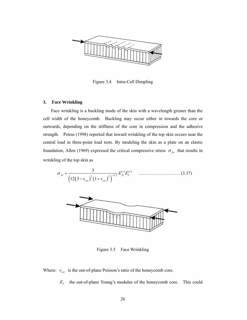
3. Face Wrinkling
Face wrinkling is a buckling mode of the skin with a wavelength greater than the
cell width of the honeycomb. Buckling may occur either in towards the core or
outwards, depending on the stiffness of the core in compression and the adhesive
strength. Petras (1998) reported that inward wrinkling of the top skin occurs near the
central load in three-point load tests. By modeling the skin as a plate on an elastic
foundation, Allen (1969) expressed the critical compressive stress fw that results in
wrinkling of the top skin as
1/3 2/3
31/32 2
3
12 3 1fw fx
cxz cxz
E Ev v
……………………… (3.37)
Figure 3.5 Face Wrinkling
Where: cxzv is the out-of-plane Poisson’s ratio of the honeycomb core.
3E the out-of-plane Young’s modulus of the honeycomb core. This could
Page 34
27
be estimated in terms of the density and elastic modulus of the honeycomb material by
the rule of mixture expression
3c
ss
E E
3.4.2 Core Failure
Honeycomb sandwich structures loaded in bending can fail due to core failure.
There are two pertinent failure modes namely shear failure or indentation by local
crushing in the vicinity of the loads.
1. Core Shear
Similar to the I-beam, the shear stress varies through plate thickness in a parabolic
way resulting in a large drop at the interface between the face and core. If the faces are
much stiffer and thinner than the core, the shear stress can be taken as linear through
the face and constant in the core. Neglecting the contribution from the skins, the mean
shear stress in the core is given by
Figure 3.6 Core Shear Failure
2cxz
VT
d ……………………… (3.38)
Assuming brittle behavior, failure occurs when the applied shear stress xzT equals the
shear strength csT of the honeycomb core in this direction.
Page 35
28
cxz csT T ……………………… (3.39)
This failure mode is very common in sandwich panels with low density Nomex core
due to the anisotropy of the honeycomb.
2. Core Crushing
This failure mode occur in sandwich panels subjected to concentrated loads at the
point of load application due to core crushing. The bending stiffness of the skin and the
core stiffness determine the degree to which the load is spread out at the point of
application (Ciba 1995; Petras 1999).
Figure 3.7 Cure Crushing Failure
3.5 Lightweight Design of LD-3 Base
Lightweight, high strength composite sandwich panels were developed and
utilized to build the scaled model air cargo prototype. The panel utilizes two
epoxy-carbon fiber composite skin plates bonded to a Nomex aramid fiber reinforced
honeycomb core. Nomex honeycomb core HD-1/8-3.0 is an extremely lightweight,
high strength and nonmetallic product manufactured with aramid fiber paper
impregnated with a heat resistant phenolic resin as shown in Figure 3.8. Aramid paper
has been used in boat hulls, auto racing bodies and military shelters (The Gill
Corporation 2015). This core was selected based on their high strength to weight ratio
and good fatigue and impact resistance. The mechanical properties of the Nomex
honeycomb core material selected for this study is summarized in TABLE 3.3.
The compressive strength 107 psi (15,408 lb/ft2) of the selected core far exceeds the
Page 36
29
minimum area load capacity of 209 lb/ft2 (10 kPa) specified for the air cargo
containers.
TABLE 3.3 Properties of Nomex Honeycomb Core
Property Value Cell Size, in. (mm) 1/8 (3.2) Density lb/ft3 (kg/m3) 3.0 (29) Compressive Strength, psi (MPa) 309 (2.13) TYP
263 (1.81) MIN L-Direction Shear Strength, psi (MPa) 224 (1.54) TYP
192 (1.32) MIN L-Direction Shear Modulus, ksi (GPa) 7.26 (0.050) W-Direction Shear Modulus, psi (GPa) 109 (0.75) TYP
193 (0.64) MIN W-Direction Shear Modulus, ksi (GPa) 3.97 (0.027)
Each of the two facings comprised four 0.118 kg/m2 (3.5 oz/sq yd) woven carbon
fiber layers with a total thickness of 0.91 mm (0.036 in.). This ultralight carbon
fabric is found suitable for applications which call for maximum strength and stiffness.
The plain weave construction delivers uniform strength in both directions, and
provides for excellent stability and easy handling. This fabric is also suitable for
Figure 3.8 Nomex Honeycomb Core HD-1/8-1.8
Page 37
30
aerospace, UAVs, competition auto and marine, and light industrial applications. The
minimum reported tensile strength for this fabric is 3.5 GPa (510 ksi) and the elastic
modulus is 227.5 GPa (33,000 ksi). A light amber laminating, medium viscosity
epoxy resin is used for fabricating all the panels.
The properties of the carbon-epoxy laminate used for this design are taken as:
Carbon / Graphite Fabric
Carbon/Epoxy Fabric, fiber volume fraction 50%.
F1t = 80 ksi
F1c = 113.0 ksi
F2t = 82.5 ksi
F2c = 98.6 ksi
E11 = 7.9 Msi
E22= 7.83 Msi
G12 = 0.59 Msi
ν12 = 0.065
Design Calculations
The LD-3 base is 61.5 in × 60.4 in.
61.5/ 1.018
60.4b a
From TABLE 3.2, for the b/a= 1.018
1
1
0.048289; 0.04827
0.004355;
0.424051; 0.42421
7
8
(a) Facing Bending Stress
2maxM pa
Page 38
31
20.048289 (0.9676) 60.4 174.74 in.lb/in
174.74
9,056 psi0.036 0.5036 1f
f
M
t hb < (F1t = 80 ksi)
Check that stress is less than the critical stresses for intra-cell buckling
32
22
2 7.83 102 2 2 0.036
1 0.251 0.065
1,304ksi
fxfi
fxy
E t
v
Check that stress is less than the critical stresses for face wrinkling
1/3 2/3
31/32 2
3
12 3 1fw fx
cxz cxz
E Ev v
For the Nomex material, 0.4cxz sv
And 345.18lb/fts
33
3130.534 8.668ksi
45.18E
1/3 2/3
1/32 2
37,900 8.668
12 3 0.4 1 0.4
1,365ksi
Therefore, yielding is the critical failure mode for the proposed face sheet. The factor
of safety for bending is
80,000
8.839,056
FOS
(b) Core Shear Stress
max1x LV V pa
0.4242 0.9676 60.4 24.78 lb/in.
24.78
46.24 psi1 0.572
L Lc
V
bh
Page 39
32
2244.84
46.24FOS
0.4240 0.9676 60.4 24.79 lb/in.
24.78
46.25psi1 0.572
W WLc
V
bh
1092.36
46.25FOS
The shear controls the design of this proposed panel.
(c) Panel Deflection
2
22 1f f
sand
f
E t hD
26
2
10.20 10 0.036 0.53659,194
2 1 0.33sandD
4
max
paw
D
4
max
0.9676 600.00435
.4
595
944
,1w
= 0.94 inch
The weight of the eight epoxy carbon fiber laminates = 5.02 lb
The weight of the 0.5inch thick honeycomb core = 3.22 lb
The overall weight of the base panel = 8.22 lb.
The current design configuration for LD-3 base utilizes either an aluminum plate
aluminum plate or glass fiber composite plate. The amount of information about the
structural design details of the existing air cargo containers is very limited. The
lightest tare weight reported for a classic aluminum LD-3 container is 76 kg (186 lb).
Such a container utilizes a 0.1 inch (2.5 mm) thick aluminum base plate whose weight
maxy WV V pa
Page 40
33
is 36.2 lb (16.5 kg), which represents approximately 22 percent of the container weight
(Nordisk 2016). This 2.5 mm thick aluminum plate needs to be stiffened in order to
meet the strength and stiffness requirements of the ULDs, but such details are not
available. The thickness of the glass fiber composite plate could not be found in the
literature.
The results above reveal that the current weight of a baseline LD-3 air cargo
container can be reduced by as much as 77 percent when the aluminum plates are
replaced, through an integrated design approach, by a composite sandwich panel.
The concept could be also extended to redesign the whole assembly of the container.
The joining concept developed during prototyping by flanging the sidewalls and
bonding or clamping them to the base would allow for fastener-free joints and reduce
weight associated with joining hardware.
Page 41
34
Chapter 4
Prototyping of Lightweight ULD
4.1 Introduction
This Chapter describes the construction of a scaled prototype of a ULD-3 air cargo
container. The main purpose of building a solid model is to explore the potential
benefits and drawbacks of various joining configurations and sandwich composite
implementation. The construction of such a model provides reliable, extensive data
for comparative assessments of alternative manufacturing and joining methods as well
as material selection. The manufacturing and close examination of such a scaled model
is necessary in order to reduce the cost of tooling and materials that to be used at a
later stage, for producing full-scale prototypes.
The primary design criteria guiding the fabrication of a scaled trailer prototype are
the achieving of optimal tradeoffs between structural weight and performance, based
on extensive use of lightweight, strong and durable components, connected by
fastener-free joints that allow easy assembly and maintenance. This approach has
been proved to be cost effective and provide the means to implement high performance
advanced sandwich structures into the model design after the initial fabrication process
has been completed and studied (Prucz et al. 2004, 2006, 2009).
This section presents a brief description of the manufacturing techniques that are
available at West Virginia University and have been used in constructing the scaled
model.
4.1.1 Hand Lay-up
The hand lay-up process, also referred to as a wet lay-up, combines the
reinforcement fibers with a liquid resin in a mold. Layers of fibers are placed into the
mold and saturated with the resin. The part is hand rolled to create a uniform resin
coat and extract any voids or air pockets within the combination. Layers are added
until the thickness or desired orientation of fibers is reached. The curing process is
Page 42
35
the final stage of the hand lay-up manufacturing; it involves the chemical process of
the resin changing state from a liquid to a solid (Barbero 1998).
The lay-up process begins with the development of a proper mold to accommodate
the desired part geometry and requirements of the curing process. The material used
for a mold depends on the number of times the mold will be used, temperature and
pressure of the curing process, and the manufacturing of the mold itself. To avoid the
resin curing to the mold and damaging the finished part by forced removal, a release
agent is applied to the areas where the mold and resin come into contact. Common
release agents are wax, poly vinyl alcohol, silicones, and release fabric.
The fibers are then placed on the mold to be saturated with resin. The proper
measurements of mixing ratio of the resin and catalyst must be carefully followed and
mixed thoroughly before application. After the different layers of fabric have been
applied to the mold and saturated with the resin, hand rollers are used to compress the
layers together and against the mold. Hand rolling of the lay-up ensures removal of
any air pockets that will become voids during the curing process if not removed. The
curing process is usually done at room temperature. However, elevated pressures are
sometimes applied to the part during the curing process to remove excess resin and air
via bag molding (Barbero 1998).
4.1.2 Bag Molding
Pressure can be applied to a laminate during the curing process by using bag
molding techniques. Vacuum bagging uses a flexible plastic or bag that is placed
over the laminate and sealed. A vacuum pump is connected so the air is pumped out
from the inside of the bag which ultimately applies a uniform pressure onto the top
surface of the laminate. The pressure forces the laminate against the mold creating an
accurate resemblance to the mold geometry while removing excess resin and air [3].
The three main methods of applying a pressure to a laminate are by pressure bag,
vacuum bag, and autoclave manufacturing. Vacuum bagging is a popular
manufacturing process because it is relatively inexpensive, allows large size parts to be
manufactured, and the quality of the resulting part is mainly dependent on the
manufacturer’s skill and not a machining process.
Page 43
36
4.2 Prototyping
Lightweight, high strength composite sandwich panels were developed and
utilized to build the scaled model air cargo prototype. The panel utilizes two
epoxy-carbon fiber composite skin plates bonded to a Nomex aramid fiber reinforced
honeycomb core. Nomex honeycomb core HD-1/8-3.0 is an extremely lightweight,
high strength and nonmetallic product manufactured with aramid fiber paper
impregnated with a heat resistant phenolic resin as shown in Figure 4.1. Aramid paper
has been used in boat hulls, auto racing bodies and military shelters. This core was
selected based on their high strength to weight ratio and good fatigue and impact
resistance.
Each of the two facings comprised four 0.118 kg/m2 (3.5 oz/sq yd) woven carbon
fiber layers with a total thickness of 0.91 mm (0.036 in.). This ultralight carbon
fabric is found suitable for applications which call for maximum strength and stiffness.
The plain weave construction delivers uniform strength in both directions, and
provides for excellent stability and easy handling. This fabric is also suitable for
aerospace, UAVs, competition auto and marine, and light industrial applications.
Figure 4.2 illustrates the finished sandwich composite panel.
Each laminate was oversaturated with epoxy resin using a brush and they were
wet-laid up. The process starts with laying up the bottom face laminates and placing
them over a waxed smooth aluminum plate. The honeycomb core is placed on top
Figure 4.1 Nomex Honeycomb Core Used in Prototyping
Page 44
37
and finally the top facing. A release peel ply was placed on top of the laminate
followed by vacuum bagging film. The release peel ply provides an easy release
barrier between the laminate surface and the breather and bleeder layer that traps and
holds the excess resin from the laminate. Vacuum connector is placed at a corner to
connect the bag to vacuum tubing to the pump. For this purpose, an 1/8 HP vacuum
pump was used.
Figure 4.2 Finished Composite Sandwich Panel for ULD Base
Page 45
38
A prototype of an air cargo was constructed at a 1 to 6 scale. The side walls of
the prototype were made as a thin epoxy-carbon fiber composite laminate, however
they could be also made of sandwich composite similar to the base as illustrated in
Figure 4.3. The two sides were made flanged as shown in order to be clamped to the
main part for the ease of assembly. The assembled sides of the scaled model are
shown in Figure 4.4.
Figure 4.4 Full Scaled Model of Air Cargo Container
Figure 4.3 Side Walls of the Air Cargo Container
Page 46
39
The building of the prototype model was performed in distinctive phases in order
to allow continual assessment of the feasibility, potential advantages and disadvantages
of different design configurations. Phasing of the fabrication process allowed for
incremental improvements in the design and fabrication concepts. The first phase
was the construction of the base of the container using the lightweight sandwich panel
by utilizing vacuum bagging process. The process of fabricating this section
progressed into the side walls and provided an effective method to culminate the full
model design.
The side panels have been bonded to the base through the flanged edges in order
to secure the integrity of such joints. Furthermore, this approach would allow
structural flexibility and effectively absorb typical static, thermal, and dynamic forces
associated with typical loading scenarios. However, other mechanical joining options
by clipping were investigated in order to make the container collapsible as needed for
more flexibility.
A clip joint was made to join the sides of the container to the base and roof
assembly shown in Figure 4.4. The proposed joint is shown in Figure 4.5. The side
panels can be attached permanently through the joint by the use of adhesives or the
joint could be used as it is a mechanical joint to allow for a collapsible container.
Figure 4.5 Clip Joint for Attaching Side Walls
Page 47
40
Chapter 5
Summary and Conclusions
This study aims at developing innovative, lightweight design concepts for air
cargo containers that would allow for weight reduction in the air cargo transportation
industry. For this purpose, innovative design and assembly concepts of lightweight
design configurations of air cargo containers have been developed through the
applications of lightweight composites. A scaled model prototype of a typical air
cargo container was built to assess the technical feasibility and economic viability of
creating such a container from fiber-reinforced polymer (FRP) composite materials.
Based on the results of this study, the following conclusions could be drawn:
The current weight of a baseline LD-3 air cargo container can be reduced by as
much as 75 percent when the aluminum plates are replaced, through an
integrated design approach, by a composite sandwich panel. The concept could
be also extended to redesign the whole assembly of the container.
According to CargoComposites (2015), assuming the fuel price cost of
$2.86/gallon, the expected cost saving for 30 10-hour round-trips is $685,600.
This would achieve significant savings in fuel cost that would recover any
additional cost in the original container price.
The joining concept developed during prototyping by flanging the sidewalls and
bonding or clamping them to the base would allow for fastener-free joints and
reduce weight associated with joining hardware.
Page 48
41
REFERENCES
1. Allen, H.G. (1969). Analysis and Design of Structural Sandwich Panels, Pergamon Press, London, United Kingdom.
2. Air China Cargo
http://www.airchinacargo.com/index.php?section=0-0001-0007-0029-0044-0059
3. Air Fast Freight System http://www.airfast-freight.com/air.asp?showid=15
4. Air New Zealand http://www.airnewzealand.com/international-cargo-containers
5. ANA Cargo http://www.anacargo.jp/ja/int/service/uld/container.html 6. Atlas Logistics http://atlaslogistics.co.in/air-container.php
7. Barbero, E. (1998). Introduction to Composite Materials Design, First Edition,
CRC Press, Boca Raton, Florida, USA. 8. Bitzer, T. (1996). Honeycomb Technology Materials, Design, Manufacturing,
Applications and Testing. Chapman and hall, London, United Kingdom. 9. Boeing
http://www.boeing.com/resources/boeingdotcom/company/about_bca/pdf/CargoPalletsContainers.pdf
10. Brown, A. S. (2009). The Many Shades of Green. Mechanical Engineering,
Vol. 131, No. 1, pp. 22–8. 11. Cathay Pacific Cargo AKE
http://www.cathaypacificcargo.com/en-us/helpsupport/uldspecifications/container.aspx
12. Chep, http://www.chep.com/containers/ibcs/
13. Ciba Composites (1995). Honeycomb Sandwich Design Technology, Duxford,
England. 14. Dragonair Cargo
http://www.dragonaircargo.com/usrapps/content/shippingSpec/unitLoadDevices/uld.aspx?type=container&category=AKE
15. DSV Global Transport and Logistics
http://www.us.dsv.com/air-freight/unit-load-devices/LD3-AKE-AVE-container
Page 49
42
16. Egyptair http://www.egyptair-cargo.com/cargo/UldAK.htm 17. Emirates Sky Cargo
http://www.skycargo.com/english/about-us/unit-load-devices/?device=5 18. Federal Aviation Administration (2011). Cargo Pallets, Nets and Containers
(Unit Load Devices), Technical Standard Order TSO-C90d, Aircraft Certification Service, Washington, D.C.
19. Fedex http://www.fedex.com/us/charters/container-guide.html 20. Grange Aerospace AKE http://www.grangerplastics.com/ld3lit.pdf
21. Hexell Composites (2000). HexWeb Honeycomb Sandwich Design Technology.
Publication No. AGU 075b, Hexcel Composites, Duxford, United Kingdom. 22. Industry Experts (2013). Carbon Fibers and Carbon Fiber Reinforced Plastics
(CFRP) – A Global Market Overview. Report No. CP015, Website http://industry-experts.com/verticals/chemicalsandplastics/carbon-fibers-and-carbon-fiber-reinforced-plastics-a-global-market-overview.html
23. Industry Experts (2012). Glass Fiber Reinforcements – A Global Market
Overview. Report No. CP014, Website: 24. http://industry-experts.com/verticals/chemicalsandplastics/glass-fiber-reinfor
cements-a-global-market-overview.html 25. International Air Transport Association (2009). The IATA Technology
Roadmap Report-Third Edition. Geneva, Switzerland. 26. International Energy Agency (2009). Transport, Energy and CO2 Moving
Toward Sustainability. Paris, France.
27. Kuenzi, E.W. (1959). Edgewise Compression Strength of Panels and Flatwise Flexural Strength of Strips of Sandwich Construction, Tech. 1827, Forest Product Laboratory.
28. Mukundan, S. (2003). Structural Design and Analysis of a Lightweight
Composite Sandwich Space Radiator Panel. Masters of Science Thesis, Texas A&M University, Texas, USA.
29. Nicholls, R. (1976). Composite Construction Materials Handbook. Prentice
Hall Inc., Englewood Cliffs, New Jersey, USA.
30. Nippon Cargo Airlines http://www.nca.aero/e/service/freighter/container.html#05
31. Petras, A. (1998). Design of Sandwich Structures. Ph.D. Dissertation,
Department of Engineering, University of Cambridge, United Kingdoem.
Page 50
43
32. Profreight http://www.profreight.co.nz/Useful+Info/Airline+Pallet+Dimensions.html
33. Prucz, J.C. and S.N. Shoukry (2004). Innovative Structural and Joining
Concepts for Lightweight Design of Heavy Vehicle Systems. 2003 Annual Progress Report on Heavy Vehicle Systems, U.S. Department of Energy, Washington, D.C.
34. Prucz, J.C., Shoukry, S.N., G.W. William (2006). Innovative Structural and
Joining Concepts for Lightweight Design of Heavy Vehicle Systems. Final Report No. EE50692 submitted to FreedomCAR and Vehicle Programs, US Department of Energy.
35. Prucz, J.C., S.N. Shoukry, G.W. William (2009). Innovative Structural Concepts for Lightweight Design of Heavy Vehicle Systems. SAE International Journal of Commercial vehicles, Vol. 1, No. 1, pp. 367-372.
36. Quantum Transportation LTD
http://www.nordisk-aviation.com/main/en/ld-containers/nordisk-classic/nordisk-ake/
37. Royal Jordanian Cargo
http://rj-cargo.com/Portals/0/images/uld_pdf/img_ld3_ake_ave.pdf
38. Schwingshackl, C.W., G.S. Aglietti and P.R. Cunningham (2006). Determination of Honeycomb Material Properties: Existing Theories and an Alternative Dynamic Approach. Journal of Aerospace Engineering, ASCE, Vol. 19, No. 3, pp. 177-183.
39. Sea Rates https://www.searates.com/reference/uld/ 40. Seidl, R.J. (1956). Paper Honeycomb-Cores for Structural Sandwich Panels.
Report No. 1918, Forest Products Laboratory, Forest Service, U. S. Department of Agriculture, Madison, Wisconsin, USA.
41. Shapiro AKE http://www.shapiro.com/resource-center/resources/air-freight-container-specifications/
42. Society of Automotive Engineers (2009). Air Cargo Unit Load Devices – Load Distribution Model, SAE AS36101 Rev. A, Warrendale, Pennsylvania, USA.
43. Society of Automotive Engineers (2011). Air Cargo Unit Load Devices –
Reference Documents, SAE AIR 36105 Rev. A, Warrendale, Pennsylvania, USA.
44. Society of Automotive Engineers (2012). Air Cargo Unit Load Devices –
Page 51
44
Testing Devices, SAE AS36102 Rev. A, Warrendale, Pennsylvania, USA. 45. Society of Automotive Engineers (2014). Air Cargo Unit Load Devices – Use
of Airworthiness Reference Documents, SAE AIR36106 Rev. A, Warrendale, Pennsylvania, USA.
46. Society of Automotive Engineers (2013). Background and Development
Record, Aerospace Information Report AIR36108, Warrendale, Pennsylvania, USA.
47. Tetra Logistics http://tetra-logistics.herokuapp.com/air-cargo-udl2
48. Timoshenko, S., and S. Woinowsky-Krieger (1959). Theory of Plates and
Shells, Second Edition, McGraw-Hill Company, Ltd, Singapore.
49. TKM Global http://www.tkmglobal.net/air_freight.htm
50. Turkish International Forwarding & Logistic Services http://www.turkishtransporters.com/container-pallet.htm
51. The Gill Corporation (2015). GillcoreTM HD Honeycomb Product Data Sheet, The Gill Corporation, El Monte, California, USA. http://www.thegillcorp.com/datasheets/Gillcore_HD_Honeycomb.pdf
52. The Minerals, Metals and Materials Society (2012). Materials: Foundation
for the Clean Energy Age. Final Report, The Advanced Manufacturing Office - U.S. Department of Energy. http://energy.tms.org/docs/pdfs/Materials_Foundation_for_Clean_Energy_Age_Press_Final.pdf
53. The World Bank (2012). Air Transport and Energy Efficiency. Report No.
TP-38, The International for Reconstruction and Development, The World Bank, Washington, D.C., USA.
54. University of Cambridge, Department of Engineering Website.
http://www-materials.eng.cam.ac.uk/mpsite/interactive_charts/spec-spec/basic.html
55. Varma, A., and A. Clayton (2010). Moving Goods Sustainably in Surface
Transportation. Institute of Transportation Engineers Journal, Vol. 80, No. 3, pp. 20–24.
56. Vinson, J.R. (1999). The Behavior of Sandwich Structures of Isotropic and
Composite Materials, Technomic Publishing Company, Inc., Lancaster, Pennsylvania, 1999.
57. VRR Aviation http://vrr-aviation.com/product/ake-container
Page 52
45
58. Wikipedia (2014). Unit Load Device. http://en.wikipedia.org/wiki/Unit_load_device Accessed on February 9, 2014.
59. Zenkert, D. The Handbook of Sandwich Construction. Chameleon Press Ltd.,
London, United Kingdom. 1997.