72
Wednesday 15 th November 2006 Design of isolators and glove boxes/codes and design guidance Emilio Moia
| Date post: | 26-Dec-2014 |
| Category: |
Documents |
| Upload: | sweekar-borkar |
| View: | 125 times |
| Download: | 7 times |
Wednesday 15 th November 2006Design of isolators and glove boxes/codes and desig n guidance
Emilio Moia
2
Contents
1. Introduction
2. Development of isolator concept
3. Containment Isolator Standard
4. Containment Isolator Design Criteria
5. Testing
6. Example of isolator
3
Contents
1. Introduction
2. Development of isolator concept
3. Containment Isolator Standard
4. Containment Isolator Design Criteria
5. Testing
6. Example of isolator
4
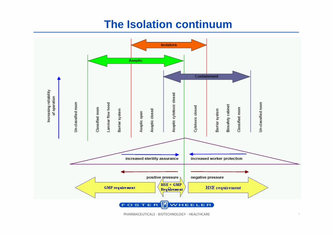
The Isolation continuum
5
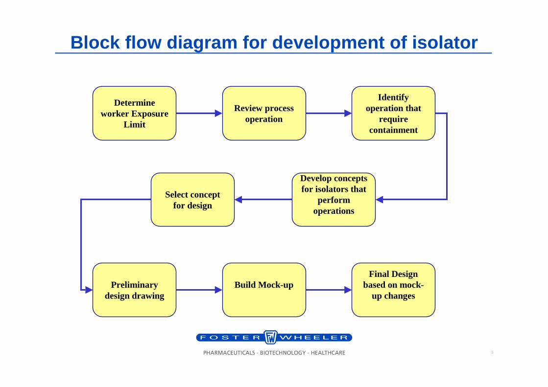
Block flow diagram for development of isolator
Identify operation that
require containment
Determine worker Exposure
Limit
Review process operation
Select concept for design
Preliminary design drawing
Build Mock-upFinal Design
based on mock-up changes
Develop concepts for isolators that
perform operations
6
Contents
1. Introduction
2. Development of isolator concept
3. Containment Isolator Standard
4. Containment Isolator Design Criteria
5. Testing
6. Example of isolator
7
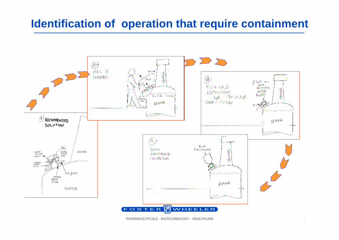
Identification of operation that require containme nt
8
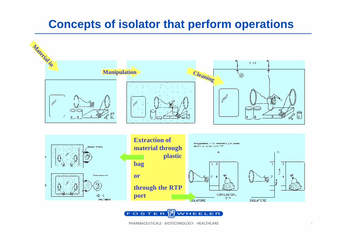
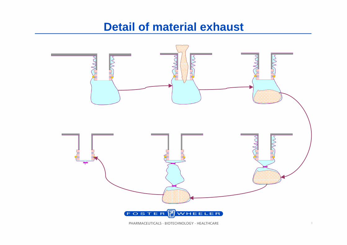
Concepts of isolator that perform operations
Extraction of material through
plastic bag
or
through the RTP port
Mater ial in
Manipulation Cleaning
9
Detail of material exhaust
10
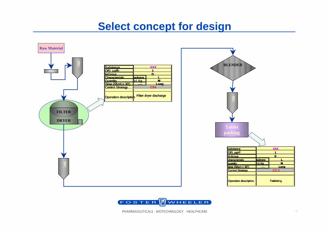
Select concept for design
IBC
Raw Material
FILTER
DRYER
BLENDER
IBC
IBC
Tablet packing
substanceOEL µg/m
3
H-Groupcharacteristic polverequanity >1 Kg time (Short:< 30') ----Control Strategy
MLong
CS 3
Operation description Tabletting
XXX1D
L
substanceOEL µg/m
3
H-Groupcharacteristic polverequanity >1 Kg time (Short:< 30') ----Control Strategy
MLong
CS 3
Operation description Tabletting
XXX1D
L
substanceOEL µg/m
3
H-Groupcharacteristic polverequanity >1 Kg time (Short:< 30') ----Control Strategy
MLong
CS 3
Operation description Tabletting
XXX1D
L
SubstanceOEL µg/m3
H-GroupCharacteristic polvereQuantity >1 Kg Time (Short:< 30') ----Control Strategy CS4
Operation description Filter dryer discharge
DLM
Long
XXX1
SubstanceOEL µg/m3
H-GroupCharacteristic polvereQuantity >1 Kg Time (Short:< 30') ----Control Strategy CS4
Operation description Filter dryer discharge
DLM
Long
XXX1
SubstanceOEL µg/m3
H-GroupCharacteristic polvereQuantity >1 Kg Time (Short:< 30') ----Control Strategy CS4
Operation description Filter dryer discharge
DLM
Long
XXX1
11
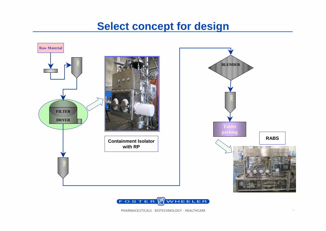
IBC
Raw Material
FILTER
DRYER
BLENDER
IBC
IBC
Tablet packing
Select concept for design
Containment Isolator with RP
RABS
12
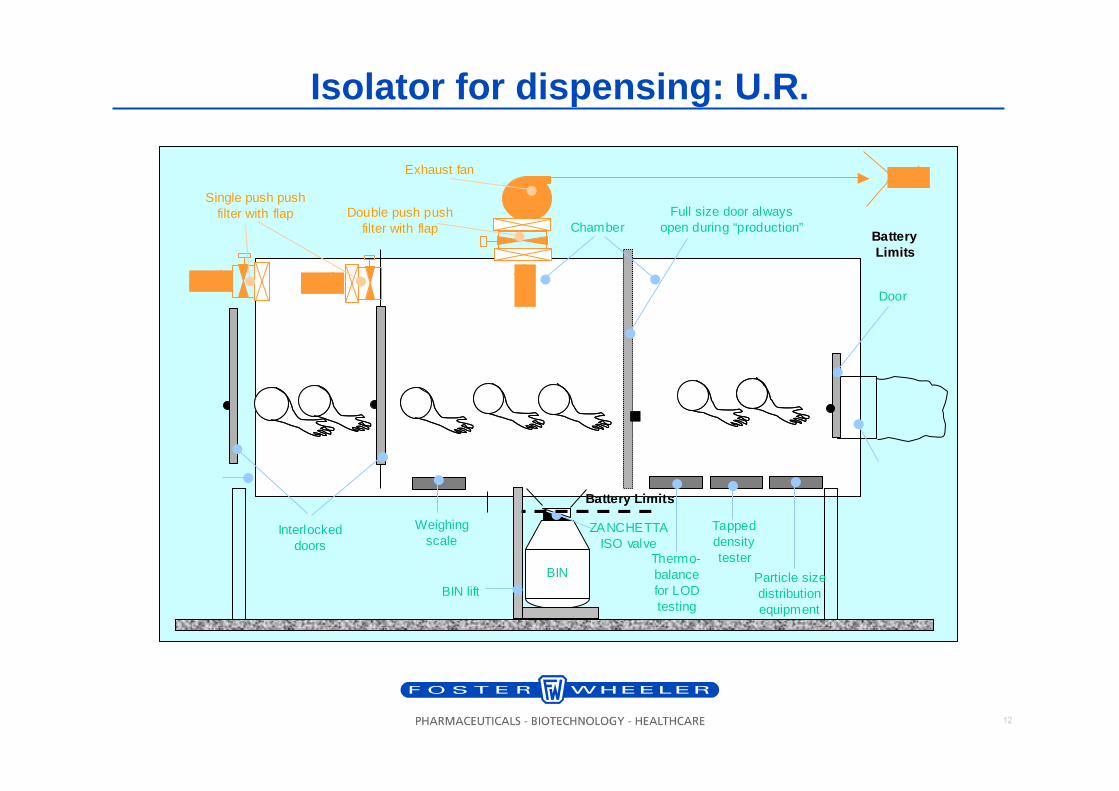
Isolator for dispensing: U.R.
Weighingscale
Chamber
Door
Interlocked doors
Full size door always open during “production”
BIN
BIN lift
ZANCHETTA ISO valve
Thermo-balance for LOD testing
Tapped density tester
Particle size distribution equipment
Double push push filter with flap
Single push push filter with flap
Exhaust fan
Battery Battery LimitsLimits
Battery LimitsBattery Limits
13
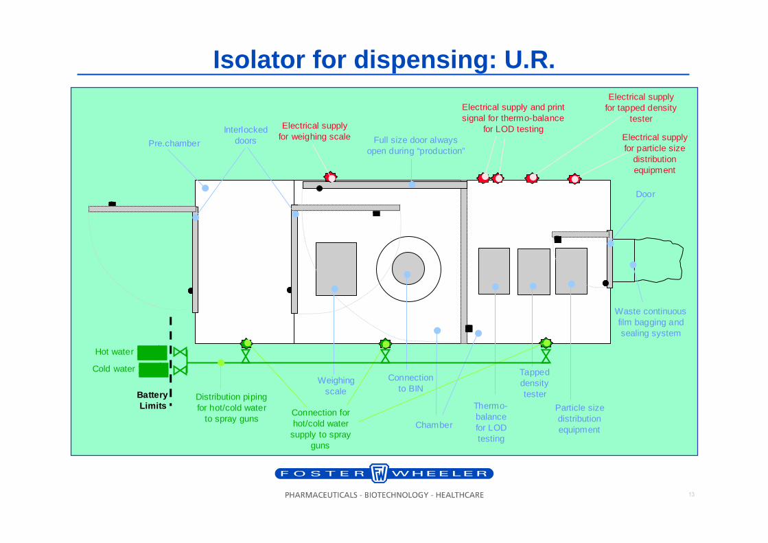
Isolator for dispensing: U.R.
Pre.chamber
Weighingscale
Chamber
Waste continuousfilm bagging andsealing system
Door
Interlocked doors Full size door always
open during “production”
Connection to BIN
Thermo-balance for LOD testing
Tappeddensity tester
Particle size distribution equipment
Electrical supply and print signal for thermo-balance
for LOD testing
Electrical supply for tapped density
tester
Electrical supply for particle size
distribution equipment
Electrical supply for weighing scale
Connection for hot/cold water
supply to spray guns
BatteryBatteryLimitsLimits
Hot water
Cold water
Distribution piping for hot/cold water
to spray guns
14
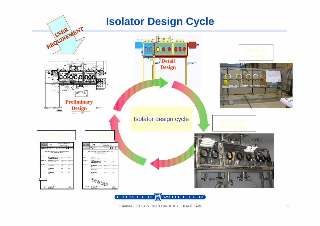
Isolator design cycle
IQ & OQFAT & SAT
Detail Design
Realization & installation
Mock-up Testing
Preliminary Design
USER USER
REQUIREMENT
REQUIREMENTIsolator Design Cycle
15
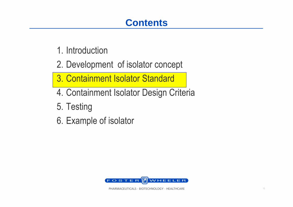
Contents
1. Introduction
2. Development of isolator concept
3. Containment Isolator Standard
4. Containment Isolator Design Criteria
5. Testing
6. Example of isolator
16
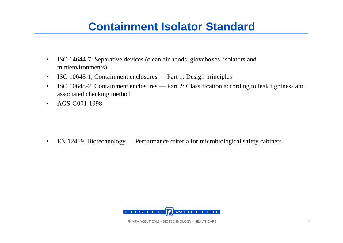
Containment Isolator Standard
• ISO 14644-7: Separative devices (clean air hoods, gloveboxes, isolators and minienvironments)
• ISO 10648-1, Containment enclosures — Part 1: Design principles
• ISO 10648-2, Containment enclosures — Part 2: Classification according to leak tightness and associated checking method
• AGS-G001-1998
• EN 12469, Biotechnology — Performance criteria for microbiological safety cabinets
17
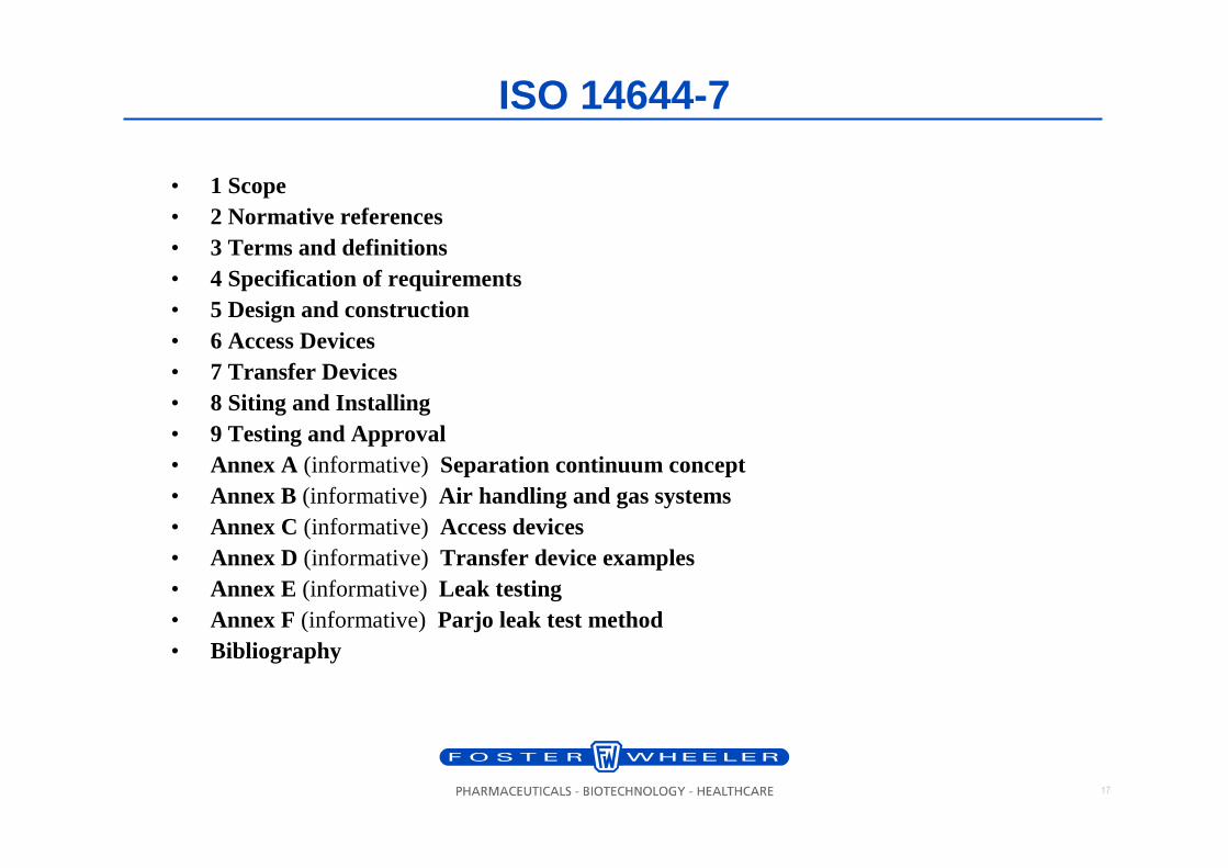
ISO 14644-7
• 1 Scope• 2 Normative references• 3 Terms and definitions• 4 Specification of requirements• 5 Design and construction• 6 Access Devices• 7 Transfer Devices• 8 Siting and Installing• 9 Testing and Approval• Annex A (informative) Separation continuum concept• Annex B (informative) Air handling and gas systems• Annex C (informative) Access devices• Annex D (informative) Transfer device examples• Annex E (informative) Leak testing• Annex F (informative) Parjo leak test method• Bibliography
18
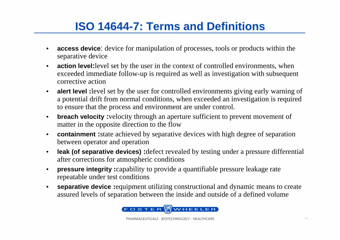
ISO 14644-7: Terms and Definitions
• access device : device for manipulation of processes, tools or products within the separative device
• action level :level set by the user in the context of controlled environments, when exceeded immediate follow-up is required as well as investigation with subsequent corrective action
• alert level :level set by the user for controlled environments giving early warning of a potential drift from normal conditions, when exceeded an investigation is required to ensure that the process and environment are under control.
• breach velocity :velocity through an aperture sufficient to prevent movement of matter in the opposite direction to the flow
• containment :state achieved by separative devices with high degree of separation between operator and operation
• leak (of separative devices) :defect revealed by testing under a pressure differential after corrections for atmospheric conditions
• pressure integrity :capability to provide a quantifiable pressure leakage rate repeatable under test conditions
• separative device :equipment utilizing constructional and dynamic means to create assured levels of separation between the inside and outside of a defined volume
19
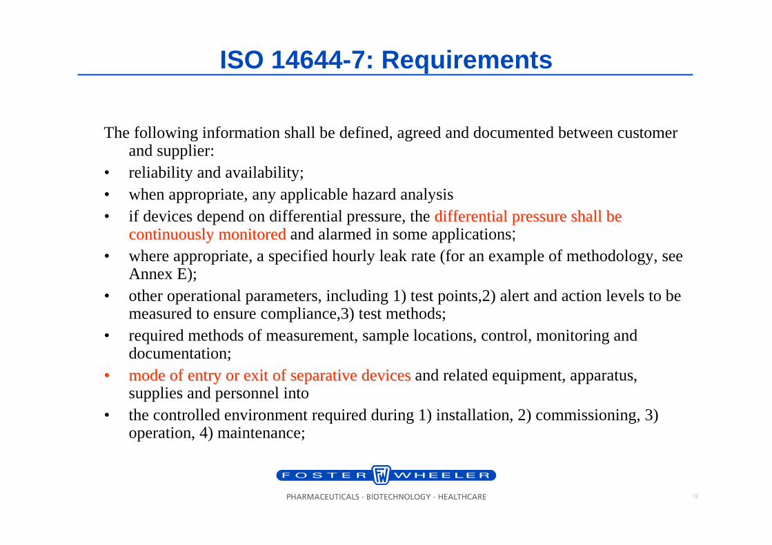
ISO 14644-7: Requirements
The following information shall be defined, agreed and documented between customer and supplier:
• reliability and availability;• when appropriate, any applicable hazard analysis• if devices depend on differential pressure, the differential pressure shall be differential pressure shall be
continuously monitoredcontinuously monitoredand alarmed in some applications;• where appropriate, a specified hourly leak rate (for an example of methodology, see
Annex E);• other operational parameters, including 1) test points,2) alert and action levels to be
measured to ensure compliance,3) test methods;• required methods of measurement, sample locations, control, monitoring and
documentation;•• mode of entry or exit of mode of entry or exit of separativeseparativedevicesdevicesand related equipment, apparatus,
supplies and personnel into• the controlled environment required during 1) installation, 2) commissioning, 3)
operation, 4) maintenance;
20
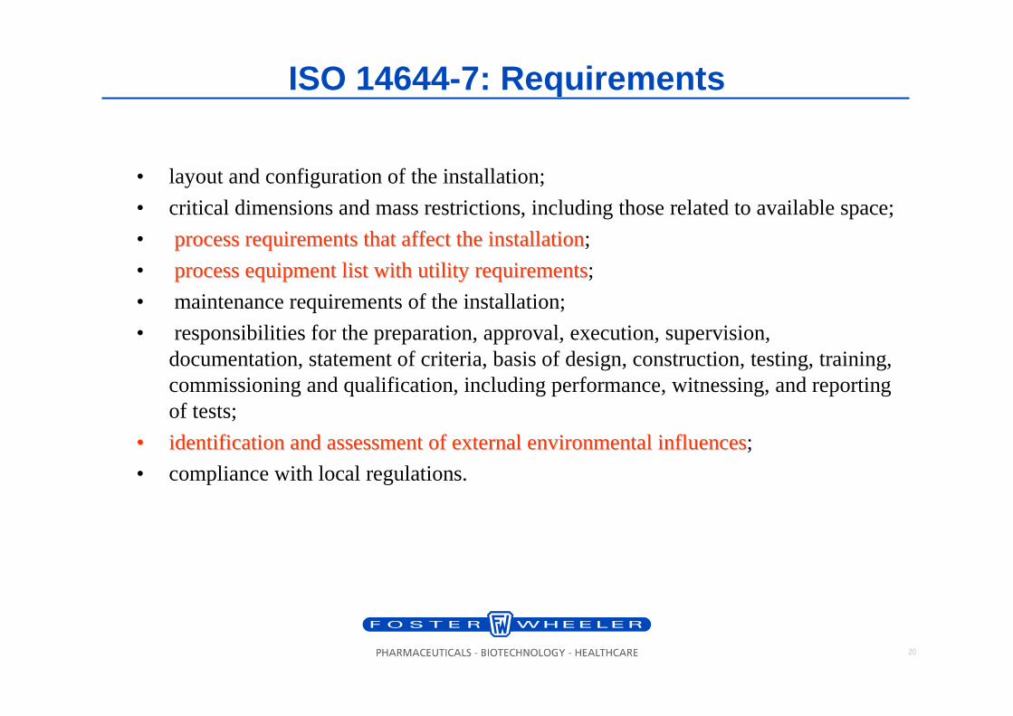
ISO 14644-7: Requirements
• layout and configuration of the installation;
• critical dimensions and mass restrictions, including those related to available space;
• process requirements that affect the installationprocess requirements that affect the installation;
• process equipment list with utility requirementsprocess equipment list with utility requirements;
• maintenance requirements of the installation;
• responsibilities for the preparation, approval, execution, supervision, documentation, statement of criteria, basis of design, construction, testing, training, commissioning and qualification, including performance, witnessing, and reporting of tests;
•• identification and assessment of external environmental influencidentification and assessment of external environmental influenceses;
• compliance with local regulations.
21
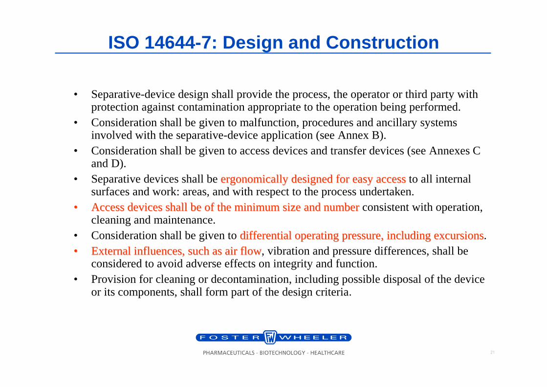
ISO 14644-7: Design and Construction
• Separative-device design shall provide the process, the operator or third party with protection against contamination appropriate to the operation being performed.
• Consideration shall be given to malfunction, procedures and ancillary systems involved with the separative-device application (see Annex B).
• Consideration shall be given to access devices and transfer devices (see Annexes C and D).
• Separative devices shall be ergonomically designed for easy accessergonomically designed for easy accessto all internal surfaces and work: areas, and with respect to the process undertaken.
•• Access devices shall be of the minimum size and numberAccess devices shall be of the minimum size and numberconsistent with operation, cleaning and maintenance.
• Consideration shall be given to differential operating pressure, including excursionsdifferential operating pressure, including excursions.•• External influences, such as air flowExternal influences, such as air flow, vibration and pressure differences, shall be
considered to avoid adverse effects on integrity and function.• Provision for cleaning or decontamination, including possible disposal of the device
or its components, shall form part of the design criteria.
22
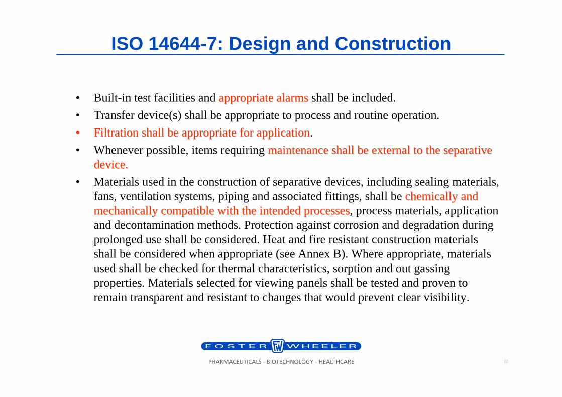
ISO 14644-7: Design and Construction
• Built-in test facilities and appropriate alarmsappropriate alarmsshall be included.
• Transfer device(s) shall be appropriate to process and routine operation.
•• Filtration shall be appropriate for applicationFiltration shall be appropriate for application.
• Whenever possible, items requiring maintenance shall be external to the maintenance shall be external to the separativeseparativedevice.device.
• Materials used in the construction of separative devices, including sealing materials, fans, ventilation systems, piping and associated fittings, shall be chemically and chemically and mechanically compatible with the intended processesmechanically compatible with the intended processes, process materials, application and decontamination methods. Protection against corrosion and degradation during prolonged use shall be considered. Heat and fire resistant construction materials shall be considered when appropriate (see Annex B). Where appropriate, materials used shall be checked for thermal characteristics, sorption and out gassing properties. Materials selected for viewing panels shall be tested and proven to remain transparent and resistant to changes that would prevent clear visibility.
23
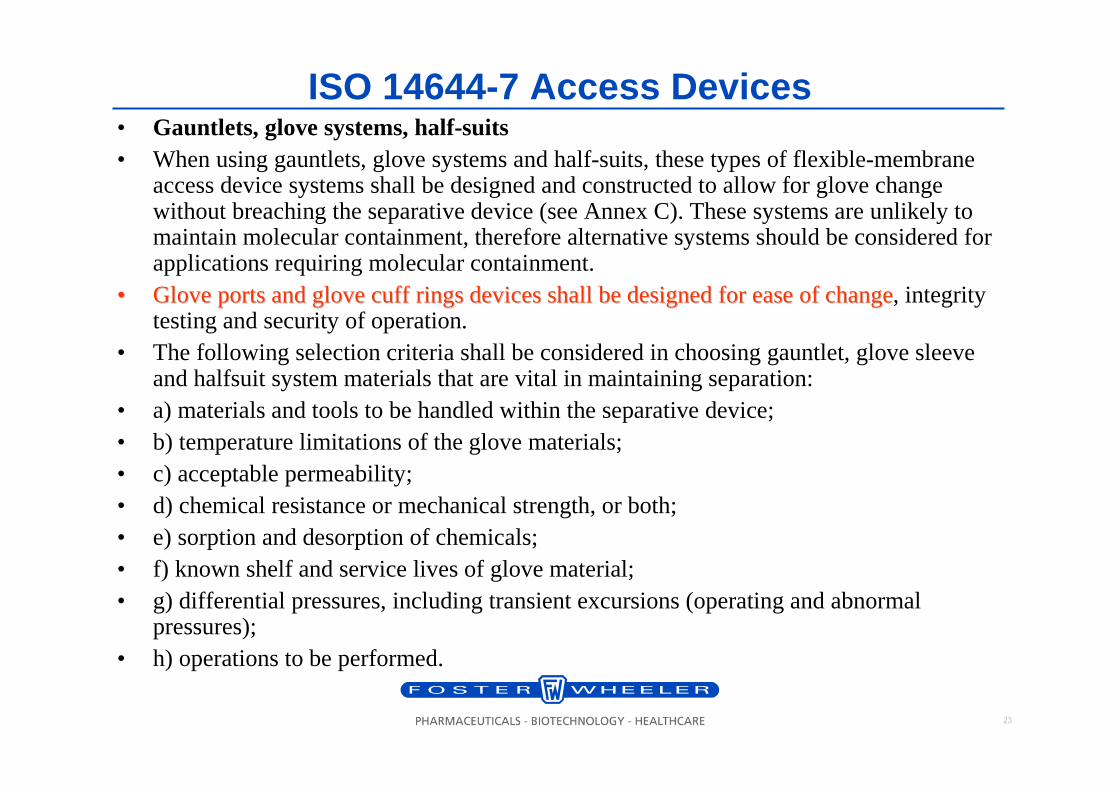
ISO 14644-7 Access Devices• Gauntlets, glove systems, half-suits• When using gauntlets, glove systems and half-suits, these types of flexible-membrane
access device systems shall be designed and constructed to allow for glove change without breaching the separative device (see Annex C). These systems are unlikely to maintain molecular containment, therefore alternative systems should be considered for applications requiring molecular containment.
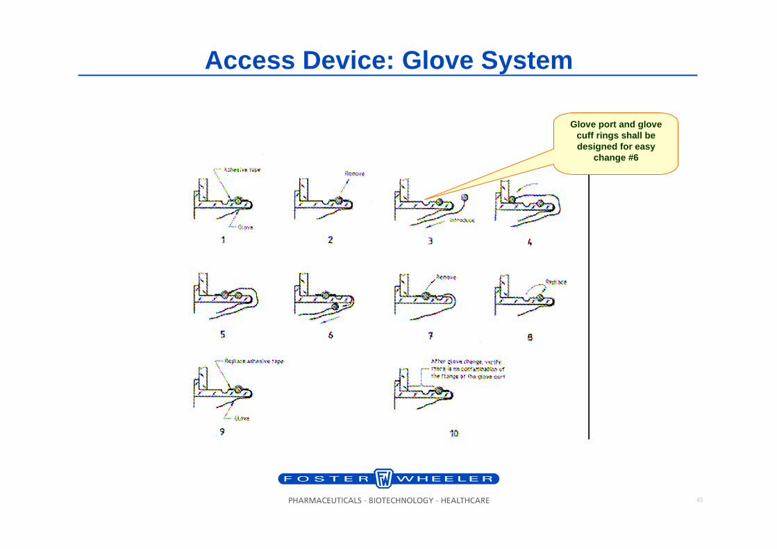
•• Glove ports and glove cuff rings devices shall be designed for eGlove ports and glove cuff rings devices shall be designed for ease of changease of change, integrity testing and security of operation.
• The following selection criteria shall be considered in choosing gauntlet, glove sleeve and halfsuit system materials that are vital in maintaining separation:
• a) materials and tools to be handled within the separative device;• b) temperature limitations of the glove materials;• c) acceptable permeability;• d) chemical resistance or mechanical strength, or both;• e) sorption and desorption of chemicals;• f) known shelf and service lives of glove material;• g) differential pressures, including transient excursions (operating and abnormal
pressures);• h) operations to be performed.

24
ISO 14644-7 Access Devices – Glove Materiala) Latex, natural rubber or cis-1,4-polyisoprene• Latex, natural rubber or cis-1,4-polyisoprene is suitable in cases where great flexibility and good
mechanical properties are necessary. However, latex articles are not impermeable to gas, perish in ozone, offer no resistance to flame, hydrocarbons and oxidising salts and poor resistance to esters, acids and bases. The potential of life-threatening allergic reactions should be considered.
b) Polychloroprene or 2-chloro-1,3-butadiene• Polychloroprene or 2-chloro-1,3-butadiene is especially recommended when good resistance to
oils and greases is needed. This chloroprene is self extinguishing, i.e. when the source of ignition is removed it no longer continues to burn. Polychloroprene is highly resistant to ozone, ultraviolet light, concentrated acids and bases, and strong oxidising agents. Polychloroprene articles are unsuitable for work with hydrocarbons, halogens and esters.
c) Nitrile or copolymer of butadiene and acrylonitrile• Nitrile or copolymer of butadiene and acrylonitrile is recommended when good resistance to
solvents is required. Nitrile articles stand up well to aliphatic hydrocarbons and hydroxyl compounds.
d) Polyvinyl chloride• Although plastic, polyvinyl chloride has a certain elasticity and is recommended for its good
electrical properties and resistance to chemical agents.e) Chlorosulfonated polyethylene• Chlorosulfonated polyethylene offers very good resistance to H2O2, and its white colour allows
good visual inspection. Other materials are resistant to H2O2, as well.
25
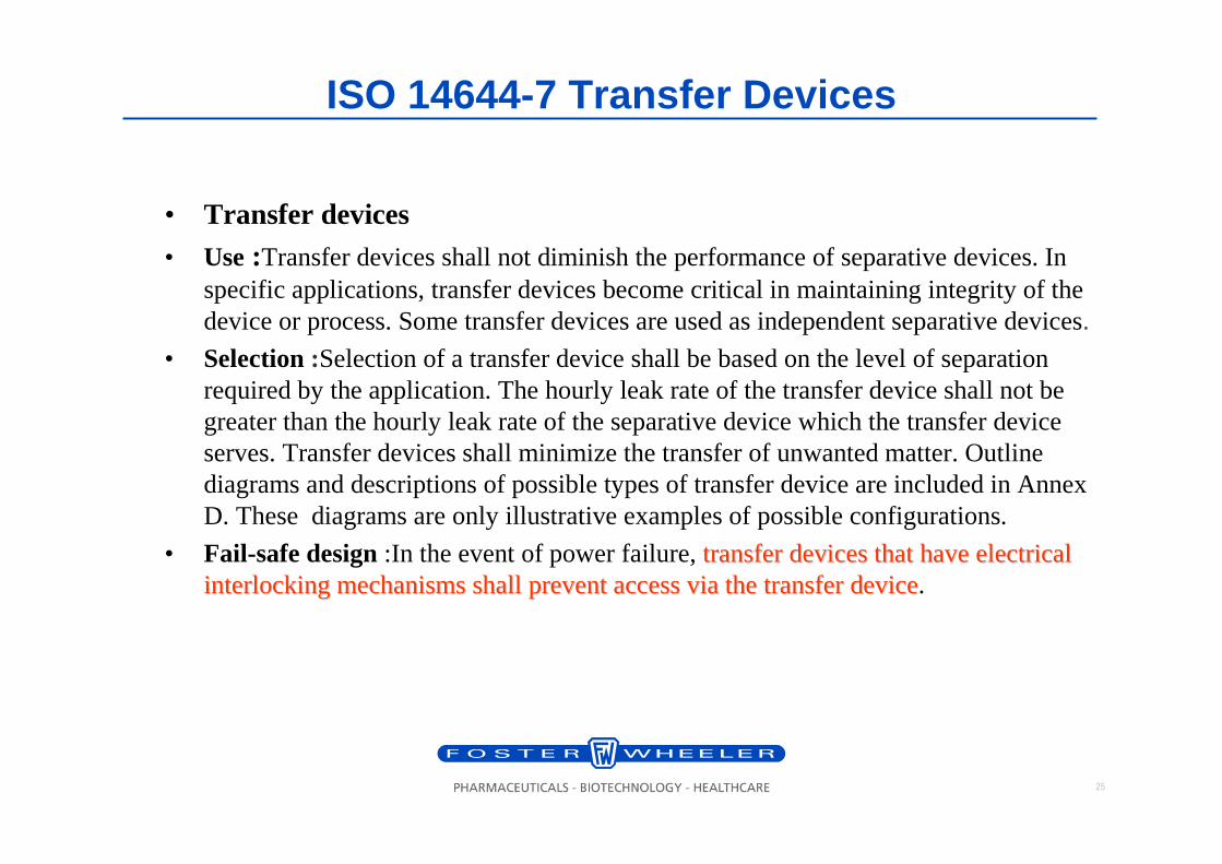
ISO 14644-7 Transfer Devices
• Transfer devices• Use:Transfer devices shall not diminish the performance of separative devices. In
specific applications, transfer devices become critical in maintaining integrity of the device or process. Some transfer devices are used as independent separative devices.
• Selection:Selection of a transfer device shall be based on the level of separation required by the application. The hourly leak rate of the transfer device shall not be greater than the hourly leak rate of the separativedevice which the transfer device serves. Transfer devices shall minimize the transfer of unwanted matter. Outline diagrams and descriptions of possible types of transfer device are included in Annex D. These diagrams are only illustrative examples of possible configurations.
• Fail-safe design:In the event of power failure, transfer devices that have electrical transfer devices that have electrical interlocking mechanisms shall prevent access via the transfer deinterlocking mechanisms shall prevent access via the transfer devicevice.
26
ISO 14644-7 Testing and Approval
Glove breach test:• When appropriate, the airflow through one open glove port shall be measured by placing an
anemometer at the centre of the glove port. The velocity shall be agreed between customer and supplier (guidance value: 0,5 m/s).
Leak testing• When appropriate, a leak test shall be performed. Guidance is given in Annexes E and F.
– NOTE Integrity testing on some separative devices that operate close to atmosphere pressure (less than 1 000 Pa) requires detailed procedures and sensitive test equipment to establish a quantifiable leak rate. The resulting leak determines acceptability for the intended application (see Annex A).
• When appropriate, an induction leak test shall be performed. Guidance is given in Annex E.– NOTE Induction leaks can occur when the velocity across an orifice creates a pressure
depression and induces a reverse flow through the orifice (Venturi effect). Devices that operate at low differential pressures may be compromised by induction leakage. Similarly, devices that utilise over pressure or flow to minimise or prevent the transfer of unwanted matter may be at risk from induction leakage when operating under transient volume changes such as glove entry or withdrawal.
27
ISO 14644-7 Testing and ApprovalPeriodic testing• The tests and checks are a function of the application and instrumentation/detection systems. Routine
tests shall be established and recorded for comparison preventative maintenance requirements.• The following recommendations for testing are given:
– a) half-suit/glove testing– 1) on commissioning,– 2) prior to and after completion of work,– 3) after glove/glove sleeve changes;
– b) pressure testing– 1) on commissioning,– 2) after any airflow or filter-pressure parameter changes,– 3) after maintenance affecting the separative device envelope or pressure control devices;
– c) induction testing on commissioning;– d) instrumentation and alarm system testing
– 1) on commissioning,– 2) after maintenance affecting the control system,– 3) at the frequency dictated by the instrumentation manufacturer,– 4) at predetermined periods consistent with use and operational requirements.
28
ISO 14644-7 Annex D
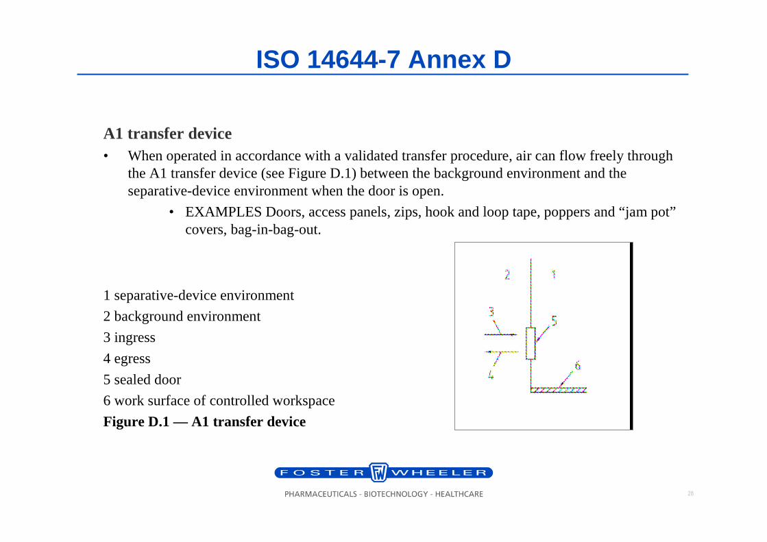
A1 transfer device• When operated in accordance with a validated transfer procedure, air can flow freely through
the A1 transfer device (see Figure D.1) between the background environment and the separative-device environment when the door is open.
• EXAMPLES Doors, access panels, zips, hook and loop tape, poppers and “jam pot”covers, bag-in-bag-out.
1 separative-device environment
2 background environment
3 ingress
4 egress
5 sealed door
6 work surface of controlled workspace
Figure D.1 — A1 transfer device
29
ISO 14644-7 Annex D
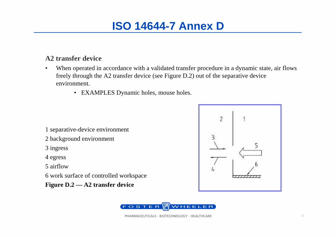
A2 transfer device• When operated in accordance with a validated transfer procedure in a dynamic state, air flows
freely through the A2 transfer device (see Figure D.2) out of the separative device environment.
• EXAMPLES Dynamic holes, mouse holes.
1 separative-device environment
2 background environment
3 ingress
4 egress
5 airflow
6 work surface of controlled workspace
Figure D.2 — A2 transfer device
30
ISO 14644-7 Annex D
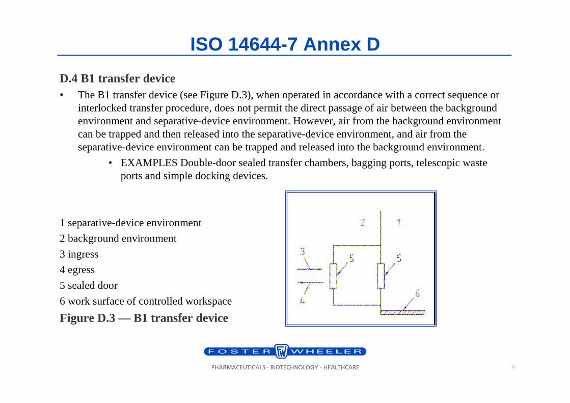
D.4 B1 transfer device• The B1 transfer device (see Figure D.3), when operated in accordance with a correct sequence or
interlocked transfer procedure, does not permit the direct passage of air between the background environment and separative-device environment. However, air from the background environmentcan be trapped and then released into the separative-device environment, and air from the separative-device environment can be trapped and released into the background environment.
• EXAMPLES Double-door sealed transfer chambers, bagging ports, telescopic waste ports and simple docking devices.
1 separative-device environment
2 background environment
3 ingress
4 egress
5 sealed door
6 work surface of controlled workspace
Figure D.3 — B1 transfer device
31
ISO 14644-7 Annex D
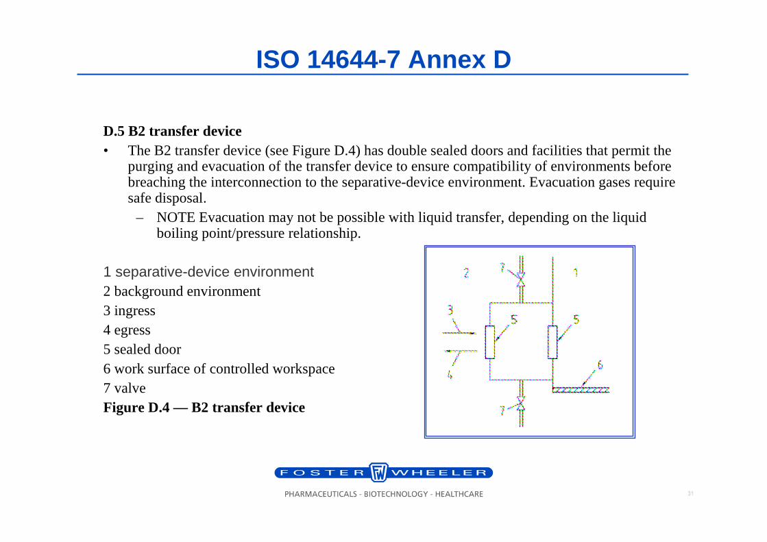
D.5 B2 transfer device• The B2 transfer device (see Figure D.4) has double sealed doors and facilities that permit the
purging and evacuation of the transfer device to ensure compatibility of environments before breaching the interconnection to the separative-device environment. Evacuation gases require safe disposal.
– NOTE Evacuation may not be possible with liquid transfer, depending on the liquid boiling point/pressure relationship.
1 separative-device environment2 background environment3 ingress4 egress5 sealed door6 work surface of controlled workspace7 valveFigure D.4 — B2 transfer device
32
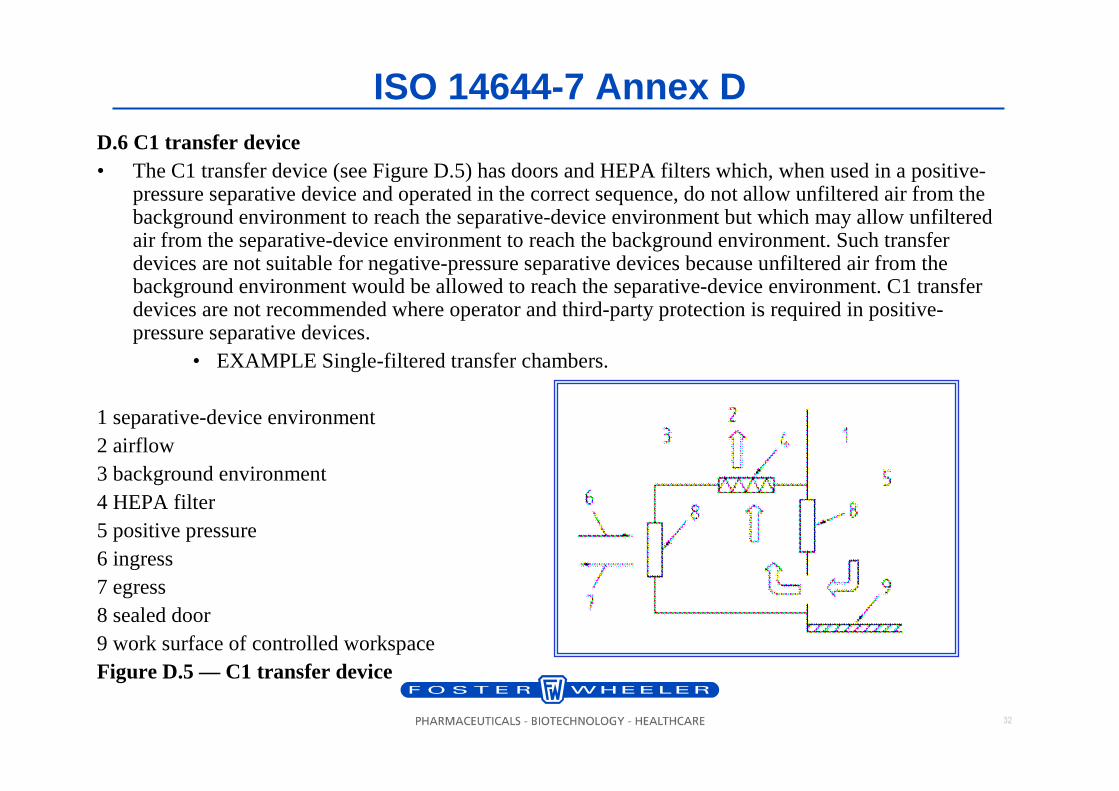
ISO 14644-7 Annex DD.6 C1 transfer device• The C1 transfer device (see Figure D.5) has doors and HEPA filters which, when used in a positive-
pressure separative device and operated in the correct sequence, do not allow unfiltered air from the background environment to reach the separative-device environment but which may allow unfiltered air from the separative-device environment to reach the background environment. Such transfer devices are not suitable for negative-pressure separative devices because unfiltered air from the background environment would be allowed to reach the separative-device environment. C1 transfer devices are not recommended where operator and third-party protection is required in positive-pressure separative devices.
• EXAMPLE Single-filtered transfer chambers.
1 separative-device environment2 airflow3 background environment4 HEPA filter5 positive pressure6 ingress7 egress8 sealed door9 work surface of controlled workspaceFigure D.5 — C1 transfer device
33
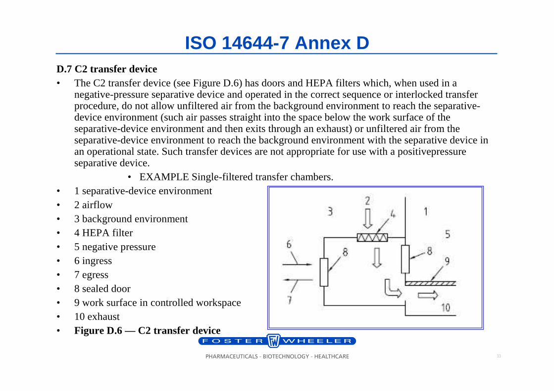
ISO 14644-7 Annex DD.7 C2 transfer device• The C2 transfer device (see Figure D.6) has doors and HEPA filters which, when used in a
negative-pressure separative device and operated in the correct sequence or interlocked transfer procedure, do not allow unfiltered air from the background environment to reach the separative-device environment (such air passes straight into the space below the work surface of the separative-device environment and then exits through an exhaust) or unfiltered air from the separative-device environment to reach the background environment with the separative device in an operational state. Such transfer devices are not appropriate for use with a positivepressure separative device.
• EXAMPLE Single-filtered transfer chambers.• 1 separative-device environment• 2 airflow• 3 background environment• 4 HEPA filter• 5 negative pressure• 6 ingress• 7 egress• 8 sealed door• 9 work surface in controlled workspace• 10 exhaust• Figure D.6 — C2 transfer device
34
ISO 14644-7 Annex D
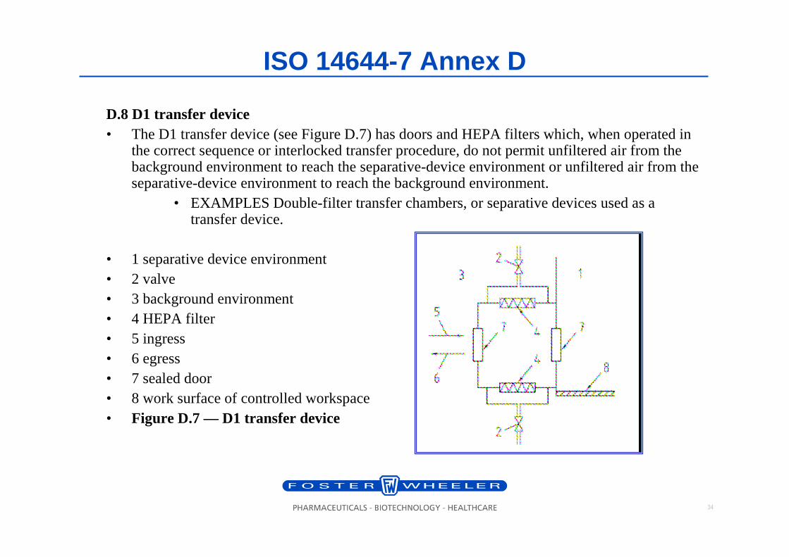
D.8 D1 transfer device• The D1 transfer device (see Figure D.7) has doors and HEPA filters which, when operated in
the correct sequence or interlocked transfer procedure, do not permit unfiltered air from the background environment to reach the separative-device environment or unfiltered air from the separative-device environment to reach the background environment.
• EXAMPLES Double-filter transfer chambers, or separative devices used as a transfer device.
• 1 separative device environment• 2 valve• 3 background environment• 4 HEPA filter• 5 ingress• 6 egress• 7 sealed door• 8 work surface of controlled workspace• Figure D.7 — D1 transfer device
35
ISO 14644-7 Annex D
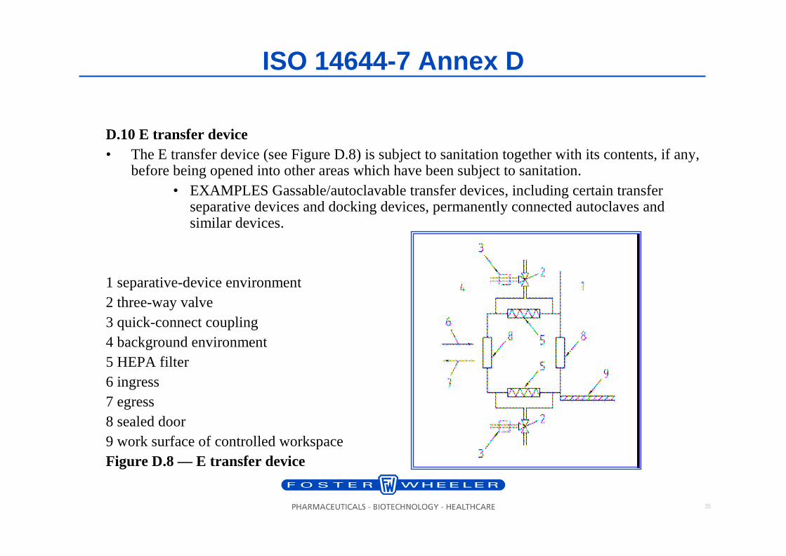
D.10 E transfer device• The E transfer device (see Figure D.8) is subject to sanitation together with its contents, if any,
before being opened into other areas which have been subject to sanitation. • EXAMPLES Gassable/autoclavable transfer devices, including certain transfer
separative devices and docking devices, permanently connected autoclaves and similar devices.
1 separative-device environment2 three-way valve3 quick-connect coupling4 background environment5 HEPA filter6 ingress7 egress8 sealed door9 work surface of controlled workspaceFigure D.8 — E transfer device
36
ISO 14644-7 Annex D
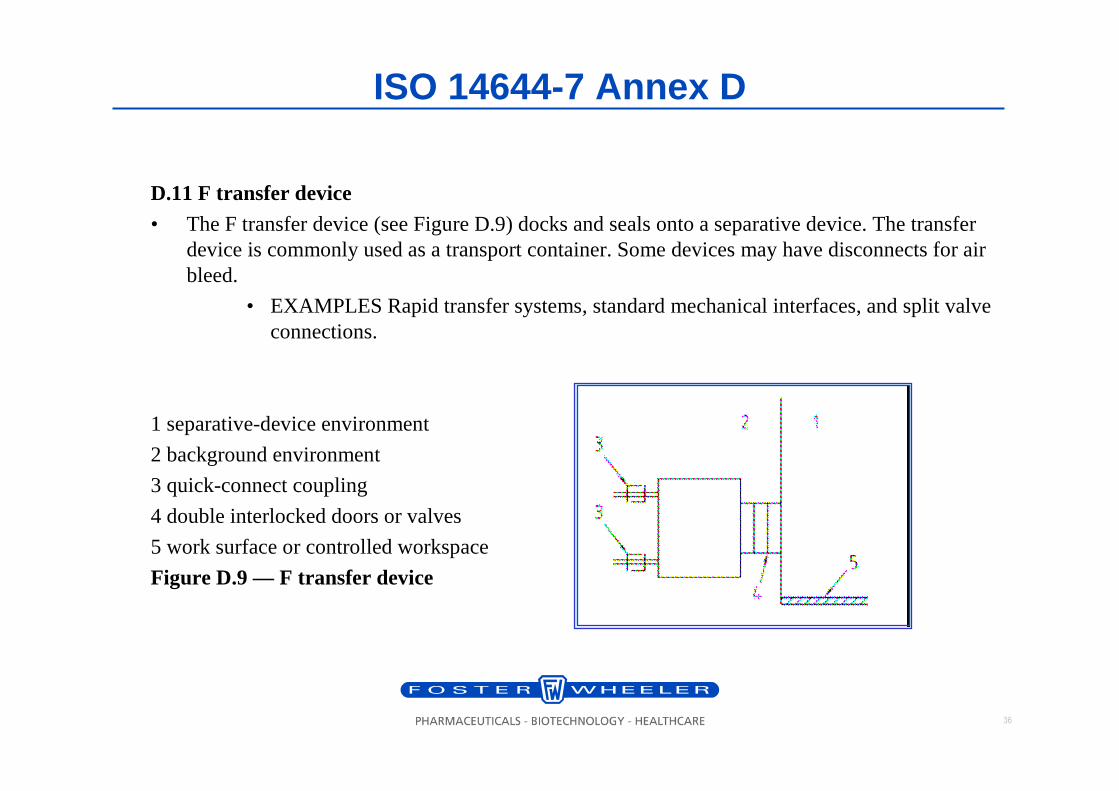
D.11 F transfer device
• The F transfer device (see Figure D.9) docks and seals onto a separative device. The transfer device is commonly used as a transport container. Some devices may have disconnects for air bleed.
• EXAMPLES Rapid transfer systems, standard mechanical interfaces, and split valve connections.
1 separative-device environment
2 background environment
3 quick-connect coupling
4 double interlocked doors or valves
5 work surface or controlled workspace
Figure D.9 — F transfer device
37
ISO 14644-7 Leak Detection
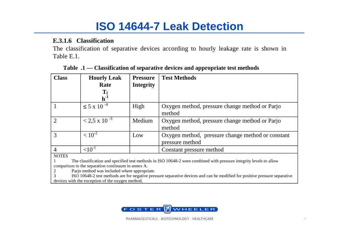
Table .1 — Classification of separative devices and appropriate test methods
Class Hourly Leak Rate T f
h-1
Pressure Integrity
Test Methods
1 ≤ 5 x 10 -4 High Oxygen method, pressure change method or Parjo method
2 < 2,5 x 10 -3 Medium Oxygen method, pressure change method or Parjo method
3 < 10-2 Low Oxygen method, pressure change method or constant pressure method
4 <10-1 Constant pressure method NOTES 1 The classification and specified test methods in ISO 10648-2 were combined with pressure integrity levels to allow comparison to the separation continuum in annex A. 2 Parjo method was included where appropriate. 3 ISO 10648-2 test methods are for negative pressure separative devices and can be modified for positive pressure separative devices with the exception of the oxygen method.
E.3.1.6 Classification The classification of separative devices according to hourly leakage rate is shown in Table E.1.
38
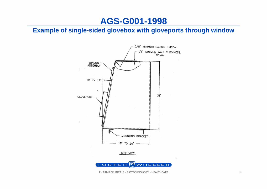
AGS-G001-1998Example of single-sided glovebox with gloveports through window
39
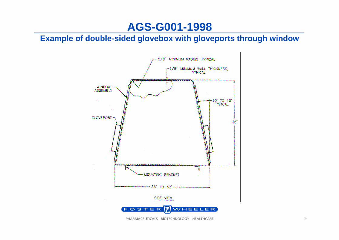
AGS-G001-1998Example of double-sided glovebox with gloveports throug h window
40
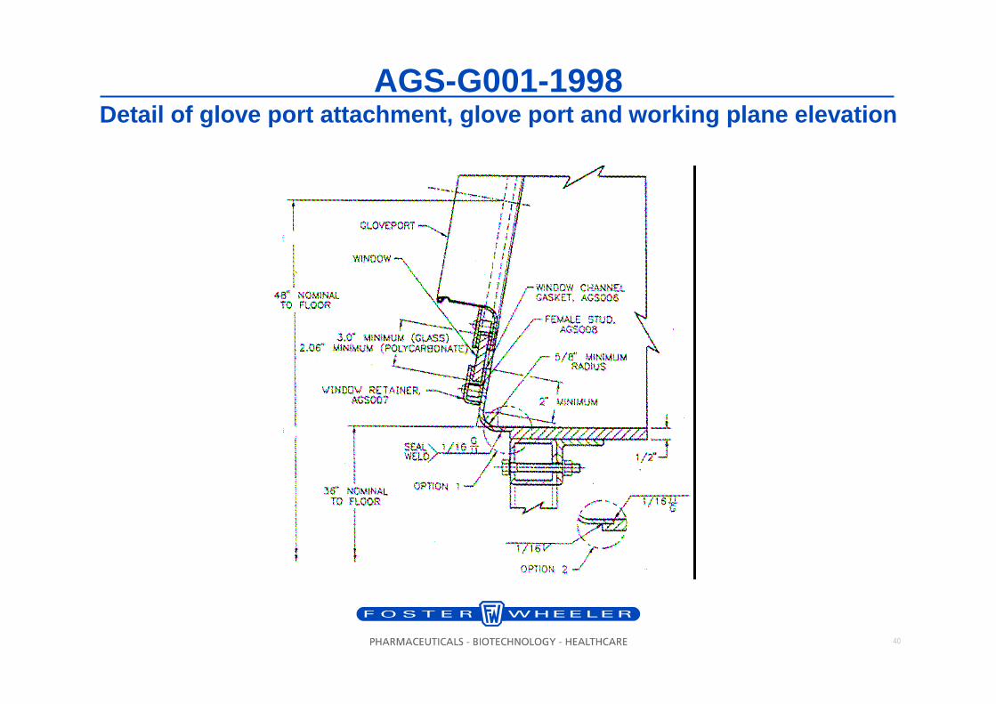
AGS-G001-1998Detail of glove port attachment, glove port and workin g plane elevation
41
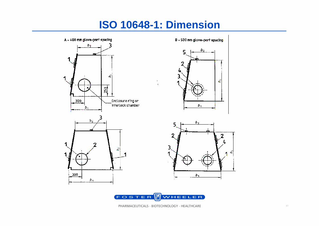
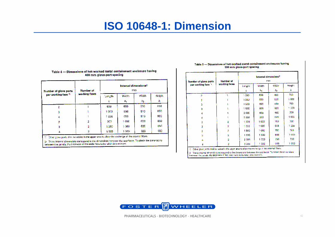
ISO 10648-1: Dimension
42
ISO 10648-1: Dimension
43
Access Device: Glove System
Glove port and glove cuff rings shall be designed for easy
change #6
44
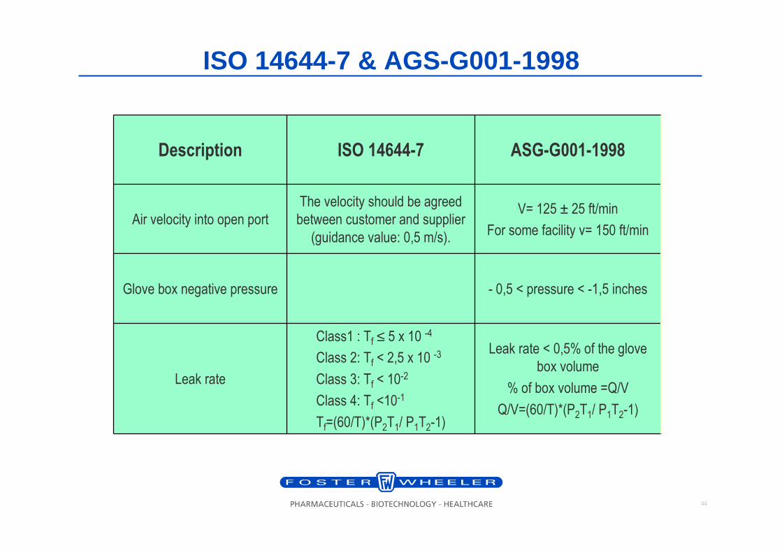
ISO 14644-7 & AGS-G001-1998
Leak rate < 0,5% of the glove
box volume
% of box volume =Q/V
Q/V=(60/T)*(P2T1/ P1T2-1)
Class1 : Tf ≤ 5 x 10 -4
Class 2: Tf < 2,5 x 10 -3
Class 3: Tf < 10-2
Class 4: Tf <10-1
Tf=(60/T)*(P2T1/ P1T2-1)
Leak rate
- 0,5 < pressure < -1,5 inchesGlove box negative pressure
V= 125 ± 25 ft/min
For some facility v= 150 ft/min
The velocity should be agreed
between customer and supplier
(guidance value: 0,5 m/s).
Air velocity into open port
ASG-G001-1998ISO 14644-7Description
45
Contents
1. Introduction
2. Development of isolator concept
3. Containment Isolator Standard
4. Containment Isolator Design Criteria
5. Testing
6. Example of isolator

46
Isolator for dispensing: Detail design and Mock-up
Ergonomic Study for easy access #5
47
D
A DF
3072001
3072
001
STERIL
08.10.04 SC PB
DISPENSING ISOLATOR IS-1500
FIRST ISSUE
NOTES
CLIENT
BATTERYLIMIT
D-1002
W-1003
G-1003 G-1008
CAB-1002
DOORG-1004 G-1007
I
PLC
D-1001G-1001
CAB-1001
DOORG-1002 G-1005
W-1001 W-1002
PUSH-PUSH
DN
80
DPI
0102
F-0103
F-0102
-
M
INVERTER
FAN-1001
INV-0110
THIMBLEDIAM. 200 mm
ZSL
0101
I
PLC
XY
0101
I
PLC
ZSL
0102
I
PLC
XY
0102
I
PLC
P&ID
DN
32
DN50
VFA-1003
F-0101
F-0106
L-1003
L-1001
(NOTE 2)
L-1002
VFA-1001
VFA-1002
DPI
0101 DPI
0106
DPI
0110
DPT
0110
0110
DPA
LIGHTING
DIVIDING SECTORD-1004
ZANCHETTA ISO VALVE
1) CONNECTION FOR SPRAY GUNTO EXHAUSTHVAC PLAN
2) CONNECTION FOR SPRAY BALL
(NOTE 3)
3) CONNECTION FOR WASTE DRAIN
VME-1001
DN20
4) CONNECTION FOR ELECTRICAL SUPPLY
DN20
DPI
0103
(NOTE 7)
(NOTE 4)
VME-1005
(NOTE 5)
5) CONNECTION FOR LINE DRAIN
SLOPESLOPE
SLOPE SLOPE
(0.3 m3/h)
LOCALPRESSURE+/- 0 Pa
B DF08.11.04 SC PB
LIGHTINGLIGHTING
D-1003
XY
0103
I
PLC
CANISTERBAG-IN BAG-OUT
CANISTERBAG-IN BAG-OUT
H
L
PUSH-PUSH
DPI
0105
DPI
0104
(85 m
3/h
)
DN
80
F-0104
F-0105
(NOTE 6)
6) FLEXIBLE FLOOR SECTION FOR WEIGH-SCALE
UPDATED AFTER CLIENT VISIT ON 18.10.04 AND 28.10.04
G-1006(NOTE 4)(NOTE 4)
SLOPE SLOPE
7) CONNECTION FOR CLEANING VACUUM
(NOTE 1)
GLOVE PORT
250
167
GUIDANCE VALUE: 0,7 m/s
GLOVE BREACH TEST
AREA PORT= 0.033 m2
Q = 0.033x0.7x3600 = 83.16 m3/h
ZSL
0103
PLC
DN20
VME-1003
DN20
DN80
DN80
DN20
DN25
DN20
DN50
DN20
(NOTE 2)DN20
VME-1002DN20
VME-1004
(NOTE 2)DN20
(NOTE 1)DN50
S
I
PLC
KY
XY
CLEANING WATER
TYPICAL 1
COMPRESSAIR
(5-7 bar)
TO ATMOSPHERE
(SEE TYP 1)
C DF10.01.05 SCUPDATED ACCORDING TO CONSTRUCTION PB
(SEE TYP 1)
(SE
E T
YP
1)
CB-0101CONTROL BOARD
CO
MP
RE
SS
AIR
(5-7
bar)
ELE
CT
RIC
AL S
UP
PLY
400V
3P
H+
N+
PE
1 K
w
d.
4/6
mm
D DF08.02.05 SC PBAS BUILT
NEGATIVEPRESSURE
-75 Pa
TO SERVICES INSTRUM COMPR AIR
(TYPICALS 1)
LETTER DATE DESCRIPTION APP.CHDBY
REV.DWG.N
APPROVED FOR CONSTRUCTION
SIGNATURE
DWG. REV. DATE
SCALE
REVISIONS
THIS DWG.SUPERSEDED BY
THIS DWG. SUPERSEDES
DWG N
THIS DRAWING IS THE PROPERTY OF STERIL AND IS LENT WITHOUT CONSIDERATION
THE APPARATUS SHOWN IN THE DRAWING IS COVERED BY PATENTS .
OTHER THAN THE BORROWER 'S AGREEMENT THAT IT SHALL NOT BE REPRODUCED
PURPOSE OTHER THAN THAT FOR WHICH IT IS SPECIFICALLY FURNISHED.
COPIED LENT OR DISPOSED OF DIRECTLY OR INDIRECTLY , NOR USED FOR ANY
cod.=
rif. SP.TEC. TOLL-001
rif. SP.TEC. PAINT-001
NOT SPECIFIED TOLLERANCE :
PAINTING:
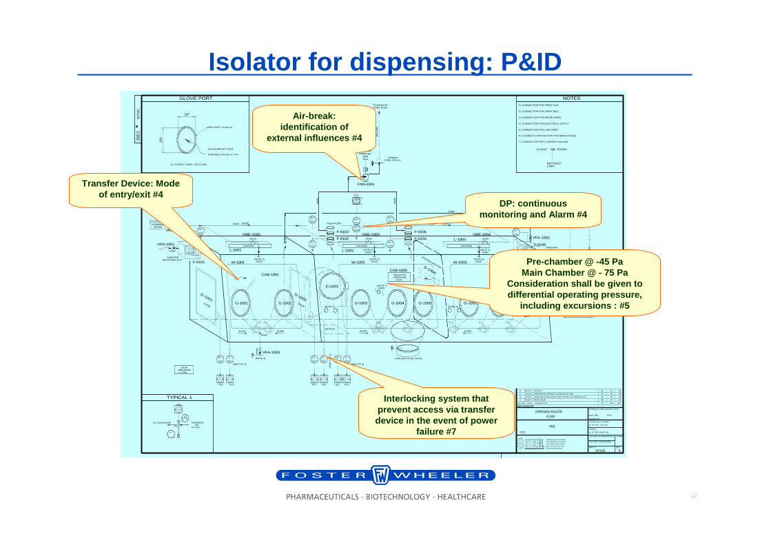
Isolator for dispensing: P&ID
Transfer Device: Mode of entry/exit #4
Air-break: identification of
external influences #4
DP: continuous monitoring and Alarm #4
Interlocking system that prevent access via transfer device in the event of power
failure #7
Pre-chamber @ -45 PaMain Chamber @ - 75 Pa
Consideration shall be given to differential operating pressure,
including excursions : #5
48
3072
.000
3072.000
A 08-10-04 DF
F
750 2250
1000
1884
3379
245 380 380 280 220
493
350
1250 1000
SI131530720
OVERALL DIMENSION
FIRST ISSUE
LIGHTING
DOUBLE PUSH-PUSH
FILTER
DISPENSING ISOLATOR IS-1500
ASSEMBLY
ELETTRICAL BOX
STAINLESS STEEL
CONNECTION FOR
SPRY BALL
DIVIDING SECTOR
CLOSE
DIVIDING SECTOR
OPEN
CONNECTION FOR
SPRY GUN
VALVE DN20
VALVE DN15
CONNECTION FOR
SPRY GUN
VALVE DN20
FLAP DN80
FLAP
DN80
PB
SLOPE
SLOPE SLOPE
B 12-10-04 DF PBCHANGING SUPPORT TYPE
1834
630
327
200
1884
FLOOR
EXHAUST FAN
FLOOR
750
600
BIN ZANCHETTA
900
80
201
167
250
450
80SLOPE
OVAL GLOVE
PORT
CANISTER FILTERBAGIN-BAGOUT
SLOPE
DOUBLE PUSH-PUSHFILTER
250
FLEXIBLE FLOOR
SECTION FORWEIGH-SCALE
INDEPENDENT SUPPORT FOR
WEIGH-SCALE
WALL STABILITYSUPPORT
WALL STABILITY
SUPPORT
FLAPDN80
WALL STABILITY
SUPPORT
CANISTER FILTER
BAG-IN/BAG-OUT
LIFTING TABLE
4590
INTERLOCKED DOOR
DIM. HOLE 350x450mm
INTERLOCKED DOOR
DIM. HOLE D.280mm
C 26-10-04 DF PB
REMOVABLE
COARSE GRID 5mm
UPDATED AFTER CLIENT VISIT ON 18.10.04
D 02-11-04 DF PBISSUED FOR APPOVAL - WHITH CLIENT COMMENT ON 28.10.04
280
400
470600
INTERLOCKED DOOR
DIM. HOLE 350x450mm
LIGHTING
220 220
2250
300
750
630
1450
1350
45
594
600
1350
3379
350
WASTE MATERIALSY STEM
VALVE DN20
327
200
1200
1350
450
EXHAUST FAN
FLOOR
857
BIN ZANCHETTA
900
1027
80
280
380
450
340
1780
1100
DOUBLE PUSH-PUSH
FILTER
LIFTING TABLE
470 600
600
220 310 220
627 576
CONNECTION TO BINZANCHETTA ISOVALVE
ELECTRIC DEVICE FOR ISOVALVE
(BY ZANCHETTA)
TO BE FIXED ON ISOLATOR
NOTES1) CONNECTION FOR SPRAY GUN
2) CONNECTION FOR SPRAY BALL
3) CONNECTION FOR WASTE DRAIN
4) CONNECTION FOR ELECTRICAL SUPPLY
5) CONNECTION FOR LINE DRAIN
6) FLEXIBLE FLOOR SECTION FOR WEIGH-SCALE
7) CONNECTION FOR CLEANING VACUUM
(NOTE 7)
(NOTE 4)
650
600
(NOTE 1, 2)
OPERATORCONTROL PANEL
OPERATORCONTROL PANEL
WALL STABILITY
SUPPORT
ELETTRICAL BOX
STAINLESS STEEL
ELECTRIC DEVICE FOR ISOVALVE
(BY ZANCHETTA)TO BE FIXED ON ISOLATOR
1700
594
SUPPORT TO BE FIXED
ON THE FLOOR
SUPPORT TO BE FIXEDON THE FLOOR
(NOTE 3)
BUTTERFLY VALVE
CLAMP 1 1/2 "
(NOTE 3)
BIN ZANCHETTA
LIFTING TABLE
TAPPED DENSITY
TESTERDIM. 330x450 h700
PARTICLE SIZE
DISTRIBUTIONEQUIPMENT
DIM. 300x350 h750
WEIGHING SCALE
DIM. 350x350 h150
INTERLOCKED DOOR
DIM. HOLE 350x450mm INTERLOCKED DOOR
DIM. HOLE 350x450mm
INTERLOCKED DOOR
DIM. HOLE D.280mm
DIVIDING SECTOR
OPEN
DIVIDING SECTORCLOSE
200
300
REMOVABLECOARSE GRID 5mm
(NOTE 6)
600
1040
(NOTE 5)
(NOTE 1, 2)
(NOTE 5)
CANISTER FILTER
BAG-IN/BAG-OUT
CONNECTION FOR
HOT WATER
VALVE DN15 VALVE DN15
VALVE DN20
LIGHTING LIGHTINGLIGHTING
OVAL GLOVE
PORT
EXHAUST FAN
400
MINIMUN FOR
MAINTENANCE
200150250150
(NOTE 4)
250
DOUBLE PUSH-PUSHFILTER
780
WASTE MATERIAL
SY STEM
SLIDING SUPPORT
FOR VISUAL WEIGHING SCALE
WALL FAN
SUPPORT
FLAP
DN80
A
A
SECTION A-A FRONT VIEW SIDE VIEW
PLANT
VIEW H2300
PLATFORM
(BY OTHERS)
PLATFORM
(BY OTHERS)
SLIDING TABLEFOR DISPLAY WEIGHING SCALE
SLIDING TABLEFOR DISLAY WEIGHING SCALE
E 19-11-04 DF PB
SC
SC
SC
SC
SC ISSUED FOR CONSTRUCTION
300 150
DISPLAY WEIGHING SCALE
DIM. 345x190 h145
F 08-02-05 DF PBSC AS BUILT
350
SLOPE
(NOTE 1, 2) (NOTE 1, 2)
VALVE DN20VALVE DN20
(NOTE 1, 2)
320
575220 220575
200
INT ERRUT T ORE GENERAL E
F IL T RO CANIST ER F - 0 1 0 6F IL T RO EXP F - 0 1 0 3 F IL T RO EXP F - 0 1 0 5
F IL T RO EXP F - 0 1 0 4F IL T RO EXP F - 0 1 0 2 F IL T RO CANIST ER F - 0 1 0 1
AL L ARM E ACUST I CO AL L ARM E VI SI VO O F F O N O F F O N
CO M ANDO L UCE CABI NAT ENSI O NE EQ UI PM ENTRESET PRO G RAM M A
CAMERA CAB- 1 0 0 2
PRESENZ A T ENSI O NE
653
LETTER DATE DESCRIPTION APP.CHDBY
REV.DWG. N
APPROVED FOR CONSTRUCTION
SIGNATURE
DWG. REV. DATE
SCALE
REVISIONS
THIS DWG.SUPERSEDED BY
THIS DWG. SUPERSEDES
DWG N
THIS DRAWING IS THE PROPERTY OF STERIL AND IS LENT WITHOUT CONSIDERATION
THE APPARATUS SHOWN IN THE DRAWING IS COVERED BY PATENTS .
OTHER THAN THE BORROWER 'S AGREEMENT THAT IT SHALL NOT BE REPRODUCED
PURPOSE OTHER THAN THAT FOR WHICH IT IS SPECIFICALLY FURNISHED.
COPIED LENT OR DISPOSED OF DIRECTLY OR INDIRECTLY , NOR USED FOR ANY
1:10
cod.=
rif. SP.TEC. TOLL-001
rif. SP.TEC. PAINT-001
NOT SPECIFIED T OLLERANCE :
PAINT ING:
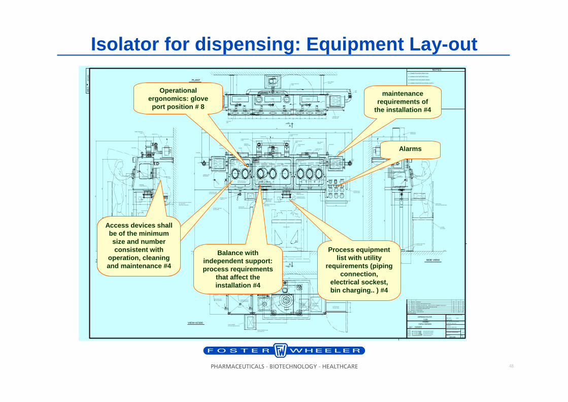
Alarms
Process equipment list with utility
requirements (piping connection,
electrical sockest, bin charging.. ) #4
Isolator for dispensing: Equipment Lay-out
Balance with independent support: process requirements
that affect the installation #4
Operational ergonomics: glove port position # 8
maintenance requirements of
the installation #4
Access devices shall be of the minimum size and number consistent with
operation, cleaning and maintenance #4
Access devices shall be of the minimum size and number consistent with
operation, cleaning and maintenance #4
49
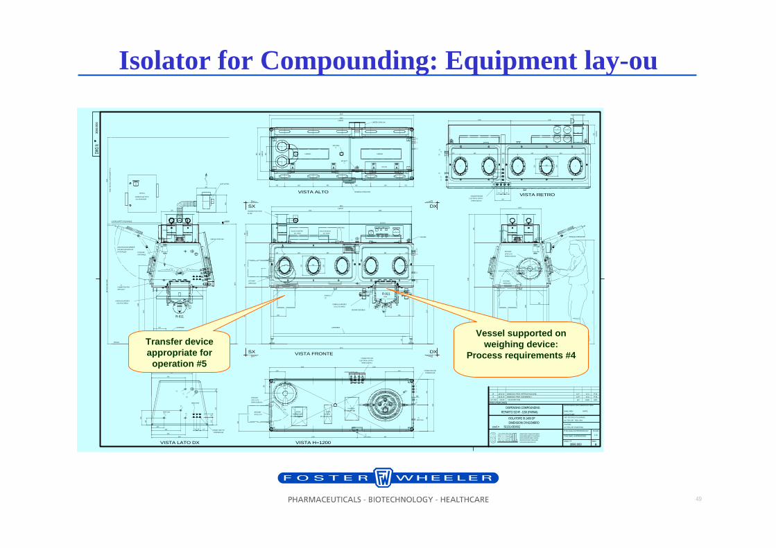
Isolator for Compounding: Equipment lay-ou30
80.0
00
240 460 460 460 220
9002273
450
10%%d
974
770
3080.000
A
1350
240 460 460 460 220
900
1116
1350
1116
450
450
450
900
2300
250
322
R-911
250
250
300
250
300
2240
2076
26.01.05 S.C.
DISPENSING COMPOUNDINGREPARTO SCHF - GSK (PARMA)
VISTA ALTO
VISTA LATO DX VISTA LATO SXVISTA FRONTE
VISTA H=1200
974
770
495
2239
656.4
VENTILATORE
RTP PORT
DPTE-S 270
CONNECTION FOR
SPRY GUN
250
339
260
1300
167
EMESSO PER COMMENTI D.F. P.B.
MIN
190
0 M
AX
200
0
1300
460
RTP PORT
DPTE-S 270
BAGNO
TERMOSTATICO
dim.240X330 h220
CORPO
BILANCIA
dim.120x330 h110
PH-METRO
dim.230x390 h100
LAMPADA LAMPADA
CARTER COPRI CAVI
PEDANA
HOUSING PUSH-PUSH
FILTER
VISIVA FRONTALE APRIBILE
CON VETRI STRATIFICATI
DI SICUREZZA
TERMINALE OPERATORE
SEZIONE FLESSIBILE
TANK
R-911
TANK
FILTER AIR
DISPOSABLE
CARTER COPRI CAVI
TERMINALE OPERATORE
CB-0102
RTP PORT
DPTE-S 270
132
CORRIPIEDE200 CORRIPIEDE
840
SX
SX DX
DX
1790
ISOLATORE IS-1400-DFDIMENSIONI D'INGOMBRO
SI131430802
+924
+3000
CB-0101
I N TE R R U TTO R E G E N E R A LE
P R E S E N ZA TE N S I O N EAL L ARME ACUST ICO AL L ARME VISIVO
OF F ON
COMANDO L UCE CABINARESET PROGRAMMA
C A B I N A D I S P E N S I N G I S - 1400
OF F ON
T ENSIONE EQUIPMENT
240460460460220
322
250
339167
FI LTR O E X P F- 0102FI LTR O E X P F- 0104
FI LTR O E X P F- 0103 FI LTR O E X P F- 0101
1000
VISTA RETRO
600
2240
1240
460
60 60 60
6060
6080
60
250
CONNECTION FOR
ELECTRICAL SUPPLY
(FORO D.22mm)
CONNECTION FOR
ELECTRICAL SUPPLY
(FORO D.22mm)
B S.C.D.F. P.B.18.02.05 EMESSO PER APPROVAZIONE
B
561
STAFFA DI SUPPORTO
CELLE DI CARICO
STAFFA DI SUPPORTO
CELLE DI CARICO
300
300
1/2" T.C.1" T.C.
1"1/2 T.C.
1/2" T.C.
3/4" T.C.
3/4" T.C.
200
465
900
540
126
256
140
50
1" T.C.AIR INLET
2" T.C.SPRY BALL
1255050
576
50
540
650
715
1/4" GMANICOTTO
SPRY BALL
2" T.C.
SCARICO
1"1/2 T.C.
MIN.
3/4" T.C.
3/4" T.C.1/2" T.C.
1/4" G1/4" G1/4" G
SPRY GUN3/4" T.C.
SPRY GUN
1/2" T.C.
1" T.C.
1"1/2 T.C.
3/4" T.C.
3/4" T.C.1/2" T.C.
1"1/2 T.C.1" T.C.1/2" T.C.
3/4" T.C.
1" T.C.
3/4" T.C.
1"1/2 T.C.1" T.C.
1/2" T.C.
1/4" G1/4" G
1050 1250
I N TE R R U TTO R E G E N E R A LE
QUADRO ELETTRICO
dim.450x600x300
RTP PORT
DPTE-S 270
(FORO D.350mm)
RTP PORT
DPTE-S 270
(FORO D.350mm)
CONTROSOFFITTO PEDONABILE
1500
VA
NO
TE
CN
ICO
CO
NT
RO
SO
FF
ITT
O
VISTA LATO DX
CONNECTION FOR
COMPRESS AIR
CONNECTION FOR
COMPRESS AIR
3/4" T.C.
CARTER COPRI CAVI
CA
RT
ERCB-0102
DISLAY PH-METRO
dim. HOLD
DISLAY BILANCIA
dim. HOLD
1240 1000CARTER
CB-0102
GOLFARE
CA
RT
ER
CA
RT
ER
600
CA
RT
ER
CARTER
1400 900
SPRY GUN
LETTER DATE DESCRIPTION APP.CHDBY
REV.DWG. N
APPROVED FOR CONSTRUCTION
SIGNATURE
DWG. REV. DATE
SCALE
REVISIONS
THIS DWG.SUPERSEDED BY
THIS DWG. SUPERSEDES
DWG
N
THIS DRAWING IS THE PROPERTY OF STERIL AND IS LENT WITHOUT CONSIDERATION
THE APPARATUS SHOWN IN THE DRAWING IS COVERED BY PATENTS .
OTHER THAN THE BORROWER 'S AGREEMENT THAT IT SHALL NOT BE REPRODUCED
PURPOSE OTHER THAN THAT FOR WHICH IT IS SPECIFICALLY FURNISHED.
COPIED LENT OR DISPOSED OF DIRECTLY OR INDIRECTLY , NOR USED FOR ANY
1:10
cod.=
ref. TEC.SP. TOLL-001
ref. TEC.SP. PAINT-001
NOT SPECIFIED TOLLERANCE :
PAINTING:
Vessel supported on weighing device:
Process requirements #4
Transfer device appropriate for
operation #5
50
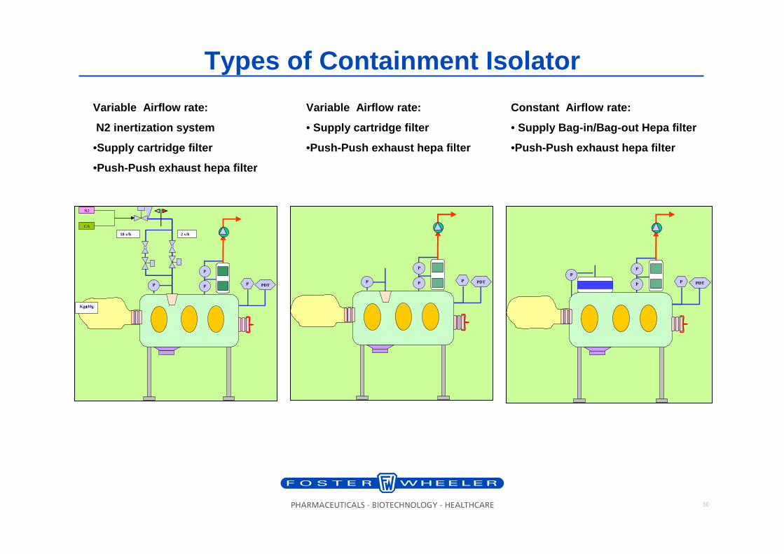
Types of Containment Isolator
N2
P
I P
I P
I
CA
P PDT
2 v/h 18 v/h
Kg±±±±10g
P
I P
I P
I P PDT
P
I P
I
P
I P PDT
Variable Airflow rate:
N2 inertization system
•Supply cartridge filter
•Push-Push exhaust hepa filter
Variable Airflow rate:
• Supply cartridge filter
•Push-Push exhaust hepa filter
Constant Airflow rate:
• Supply Bag-in/Bag-out Hepa filter
•Push-Push exhaust hepa filter
51
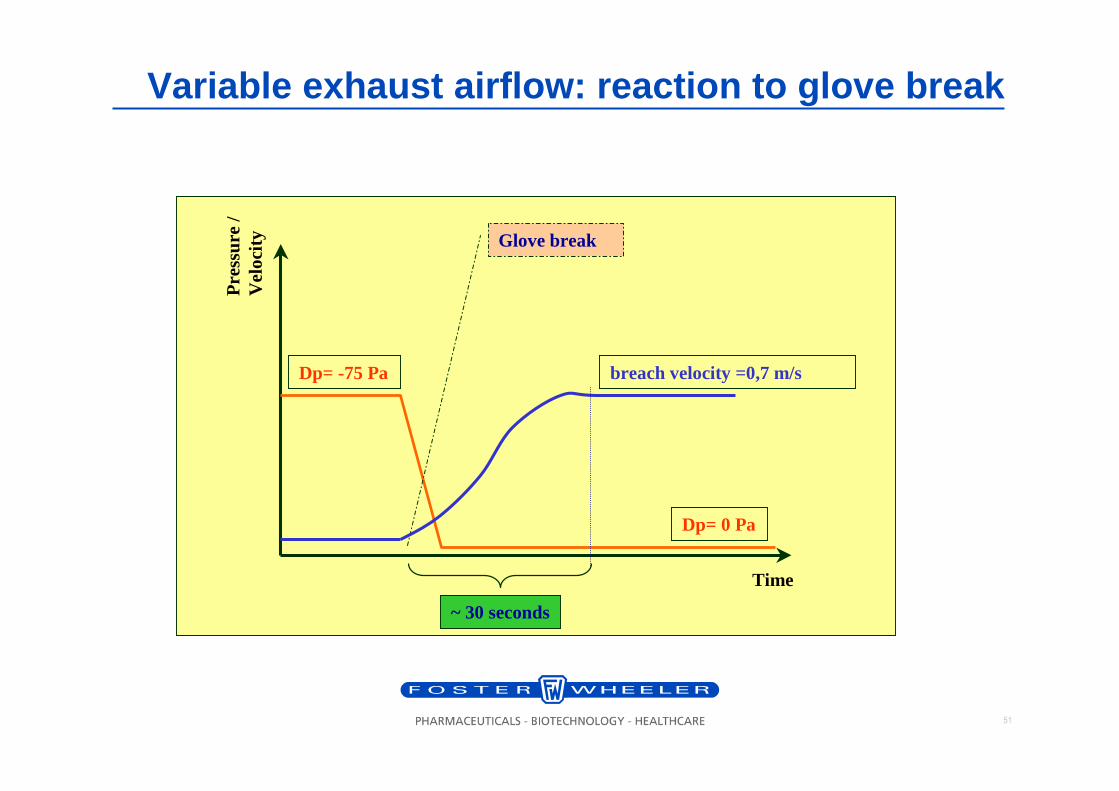
Variable exhaust airflow: reaction to glove break
Glove break
Dp= -75 Pa
Dp= 0 Pa
breach velocity =0,7 m/s
Time
Pre
ssur
e /
Vel
ocity
~ 30 seconds
52
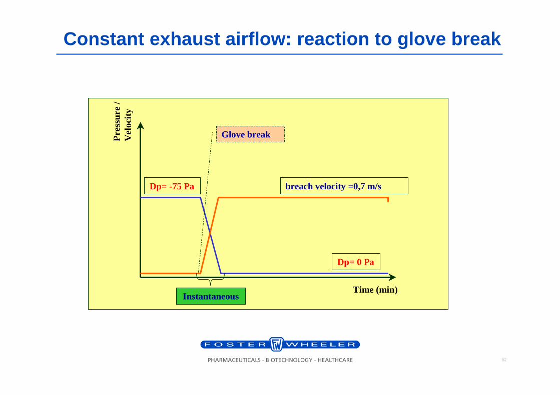
Constant exhaust airflow: reaction to glove break
Dp= -75 Pa
Dp= 0 Pa
breach velocity =0,7 m/s
Time (min)
Pre
ssur
e /
Vel
ocity
Glove break
Instantaneous
53
Contents
1. Introduction
2. Development of isolator concept
3. Containment Isolator Standard
4. Containment Isolator Design Criteria
5. Testing
6. Example of isolator
54
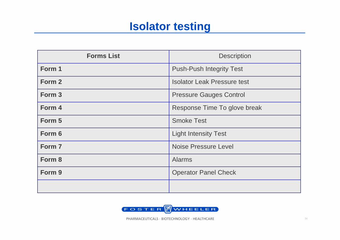
Isolator testing
Operator Panel CheckForm 9
AlarmsForm 8
Noise Pressure LevelForm 7
Light Intensity TestForm 6
Smoke TestForm 5
Response Time To glove breakForm 4
Pressure Gauges ControlForm 3
Isolator Leak Pressure testForm 2
Push-Push Integrity TestForm 1
DescriptionForms List
55
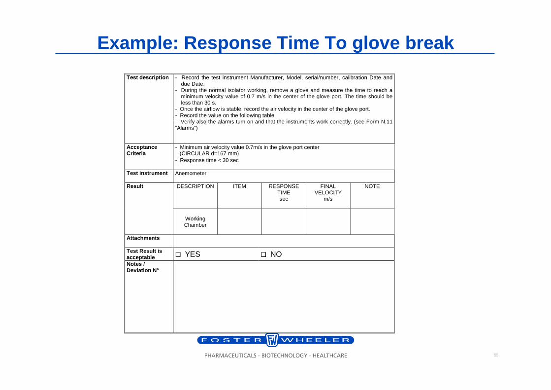
Example: Response Time To glove break
Test description - Record the test instrument Manufacturer, Model, serial/number, calibration Date and due Date.
- During the normal isolator working, remove a glove and measure the time to reach a minimum velocity value of 0.7 m/s in the center of the glove port. The time should be less than 30 s.
- Once the airflow is stable, record the air velocity in the center of the glove port. - Record the value on the following table. - Verify also the alarms turn on and that the instruments work correctly. (see Form N.11 “Alarms”)
Acceptance Criteria
- Minimum air velocity value 0.7m/s in the glove port center (CIRCULAR d=167 mm) - Response time < 30 sec
Test instrument
Anemometer DESCRIPTION
ITEM
RESPONSE
TIME sec
FINAL VELOCITY
m/s
NOTE
Result
Working Chamber
Attachments
Test Result is acceptable � YES � NO Notes / Deviation N°
56
Control System and Alarms• Control System and Alarms• Negative pressure value control by means of PLC regulation of the revolution
velocity of the motor blower. The control system modifies the motorfan speed in such way to maintain the set pressure value (-75 Pa) inside the working chamber..
• Alarm device optical (red signal light visible from working position) and acoustic (buzzer) type, activated with indication of type of alarm activate, showed on the digital display.
• Monitoring with alarms/indications of the following parameters: � • Negative pressure value inside the isolator;� • Doors opening;� • Chamber bonification;• Operator terminal/control panel showing:� • Working chamber negative pressure� • Cycle steps� • Error messages� • Indication of soft key to be pushed for proceeding to the next step� • Inlet filter clogging� • Exhaust push-push filters clogging� • Voltage presence
57
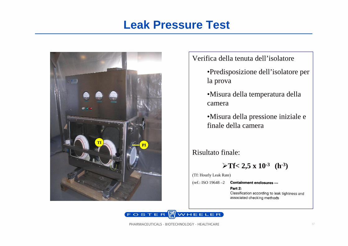
Leak Pressure Test
PI
Verifica della tenuta dell’isolatore
•Predisposizione dell’isolatore per la prova
•Misura della temperatura della camera
•Misura della pressione iniziale e finale della camera
Risultato finale:
�Tf< 2,5 x 10⁻³ (h-3)(Tf: Hourly Leak Rate)
(ref.: ISO 19648 –2
TI
58
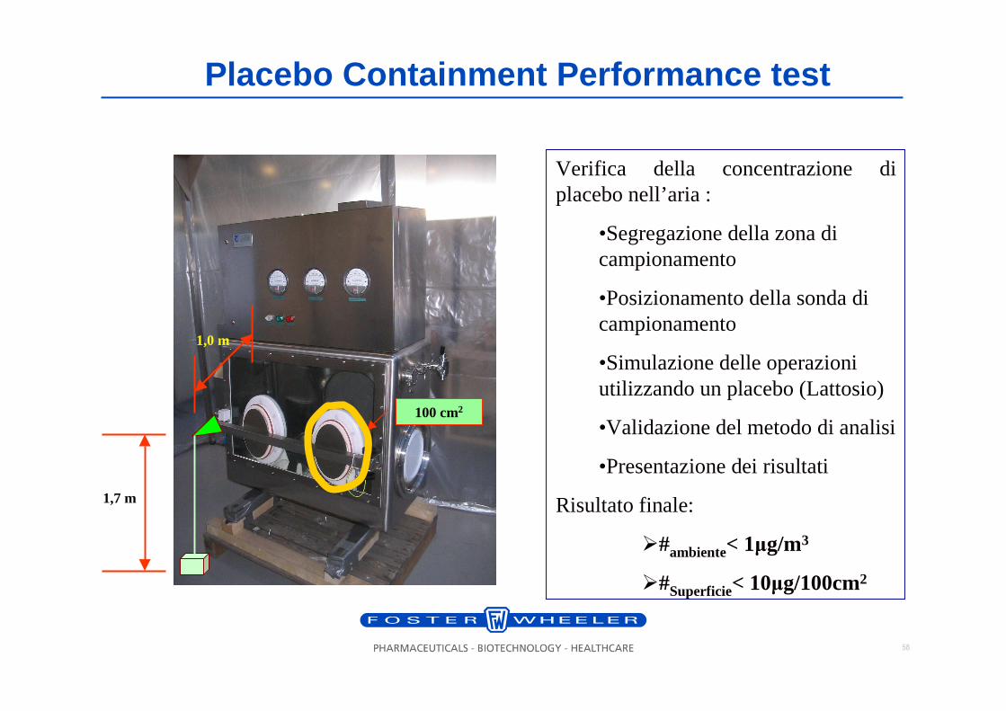
Placebo Containment Performance test
1,7 m
1,0 m
Verifica della concentrazione di placebo nell’aria :
•Segregazione della zona di campionamento
•Posizionamento della sonda di campionamento
•Simulazione delle operazioni utilizzando un placebo (Lattosio)
•Validazione del metodo di analisi
•Presentazione dei risultati
Risultato finale:
�#ambiente< 1µg/m3
�#Superficie< 10µg/100cm2
100 cm2
59
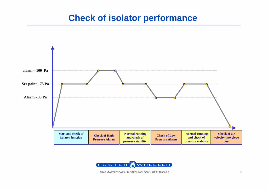
Check of isolator performance
Set-point - 75 Pa
alarm – 100 Pa
Alarm - 35 Pa
Check of High Pressure Alarm
Normal running and check of
pressure stability
Check of Low Pressure Alarm
Normal running and check of
pressure stability
Check of air velocity into glove
port
Start and check of isolator function
60
Contents
1. Introduction
2. Development of isolator concept
3. Containment Isolator Standard
4. Containment Isolator Design Criteria
5. Testing
6. Example of isolator
61
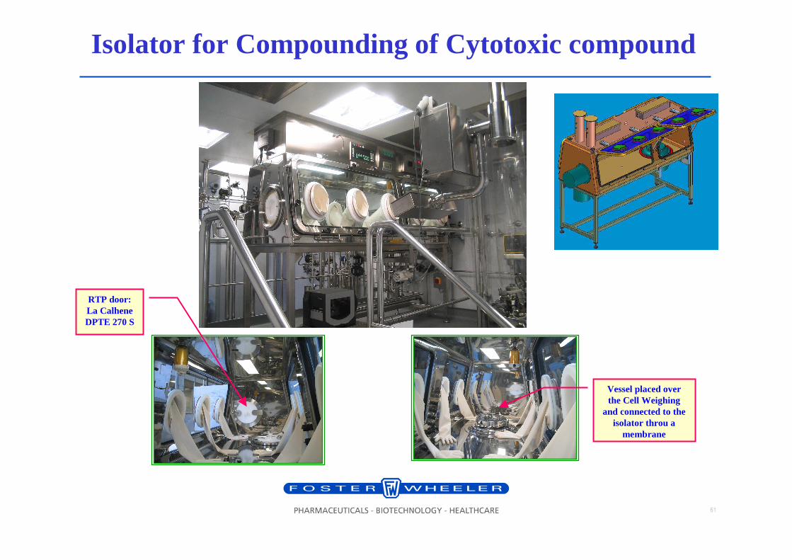
Isolator for Compounding of Cytotoxic compound
RTP door: La Calhene DPTE 270 S
Vessel placed over the Cell Weighing
and connected to the isolator throu a
membrane
62
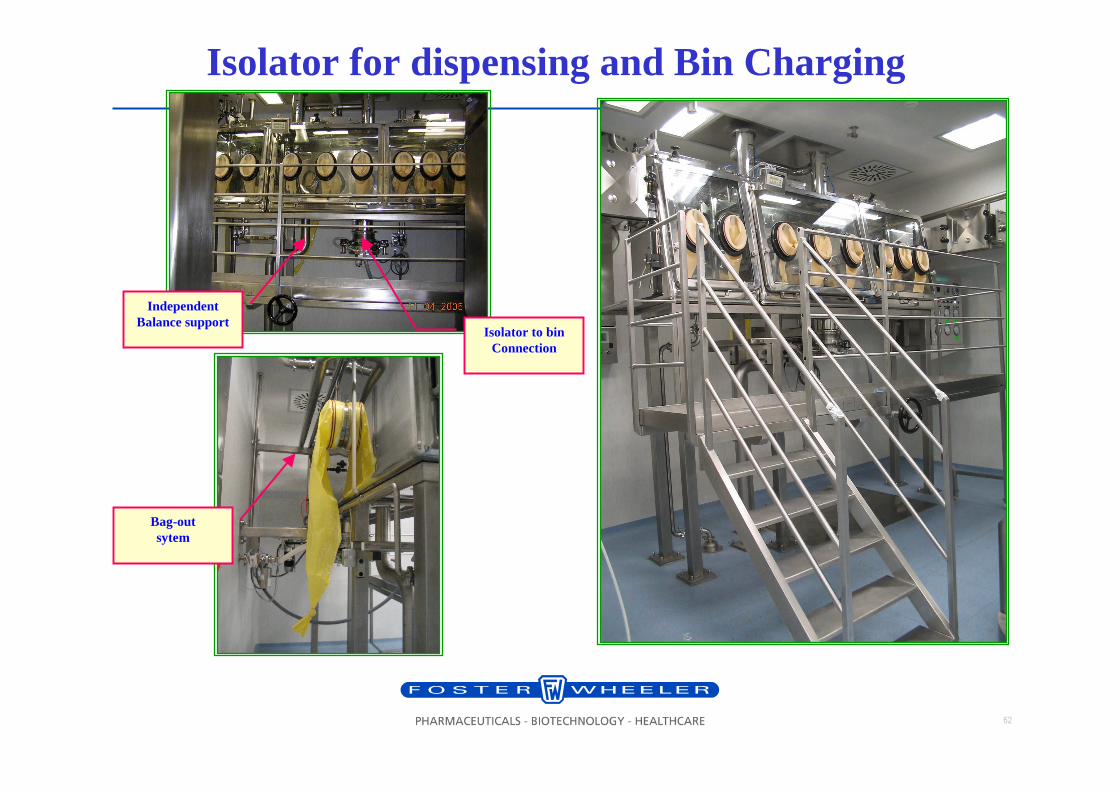
Isolator for dispensing and Bin Charging
Isolator to bin Connection
Independent Balance support
Bag-outsytem
63
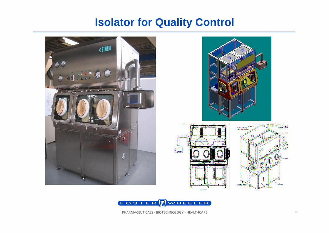
Isolator for Quality Control
64
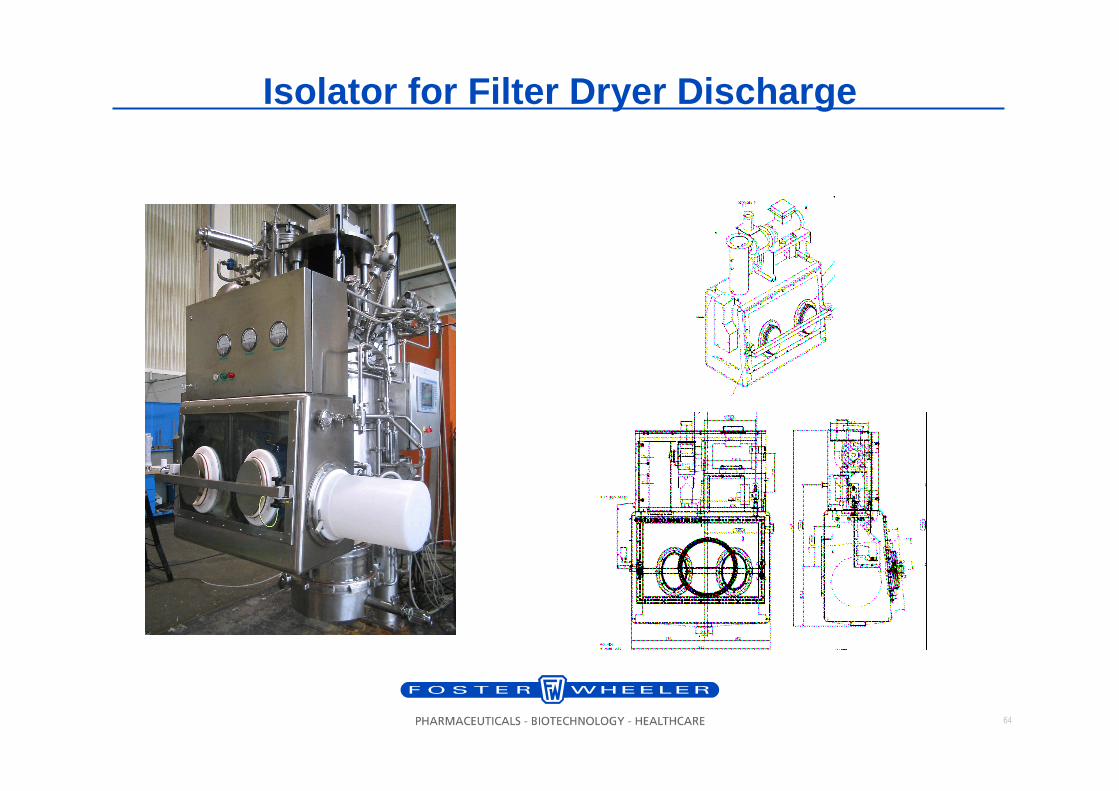
Isolator for Filter Dryer Discharge
65
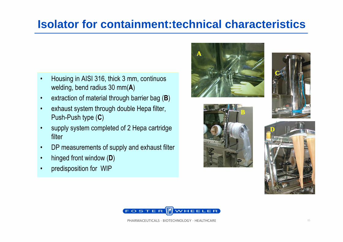
Isolator for containment:technical characteristics
• Housing in AISI 316, thick 3 mm, continuos
welding, bend radius 30 mm(AA)
• extraction of material through barrier bag (BB)
• exhaust system through double Hepa filter,
Push-Push type (CC)
• supply system completed of 2 Hepa cartridge
filter
• DP measurements of supply and exhaust filter
• hinged front window (DD)
• predisposition for WIP
AA
DD
CCBB
CC
66
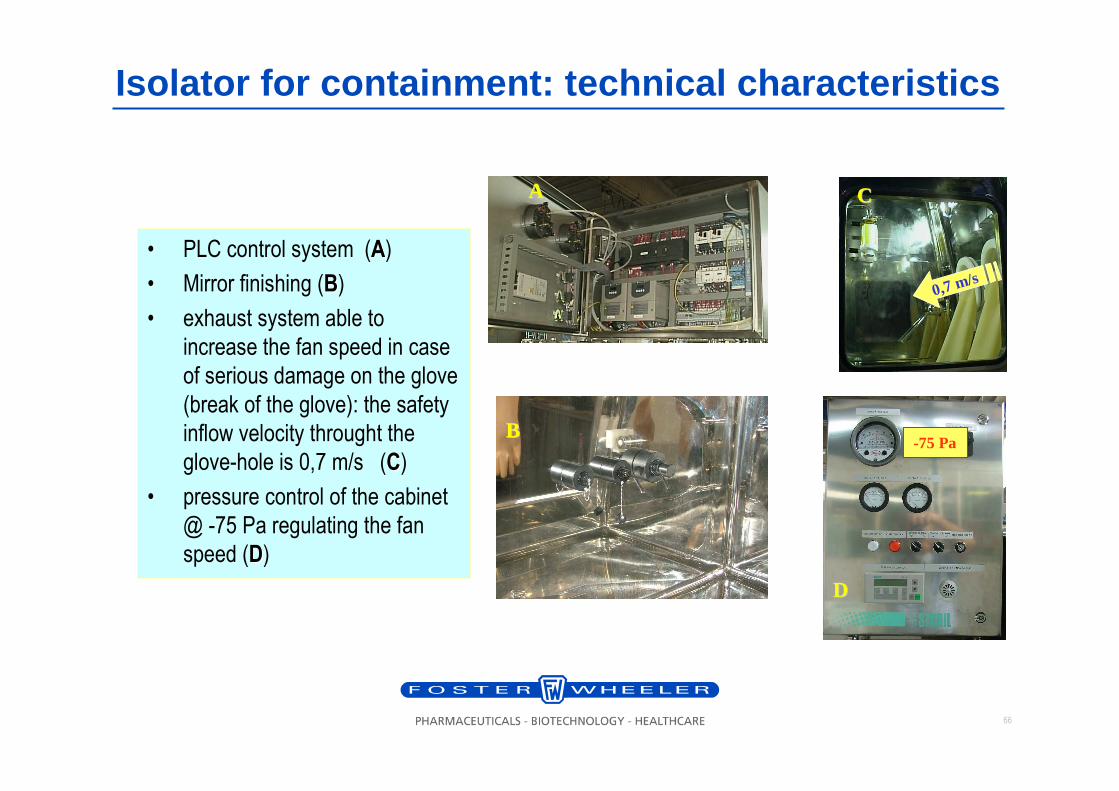
• PLC control system (AA)
• Mirror finishing (BB)
• exhaust system able to
increase the fan speed in case
of serious damage on the glove
(break of the glove): the safety
inflow velocity throught the
glove-hole is 0,7 m/s (CC)
• pressure control of the cabinet
@ -75 Pa regulating the fan
speed (DD)
0,7 m/s
AA CC
-75 Pa
Isolator for containment: technical characteristics
BB
DD
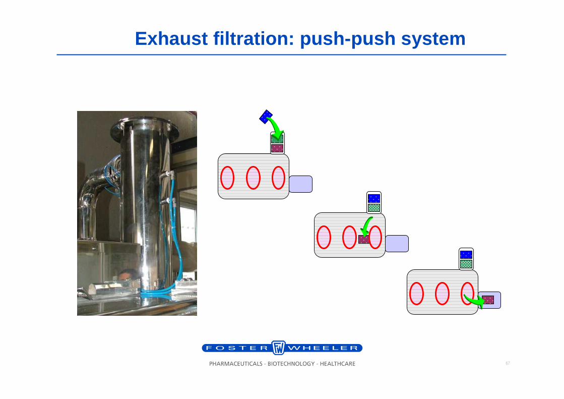
67
Exhaust filtration: push-push system
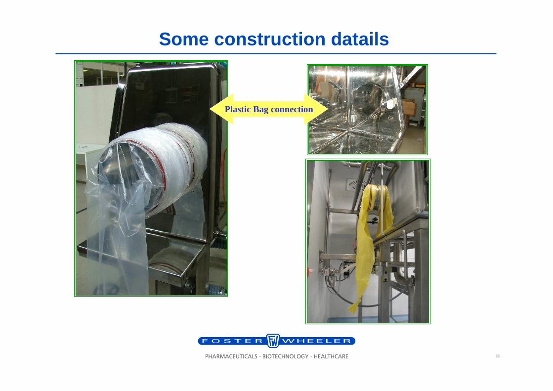
68
Some construction datails
Plastic Bag connection
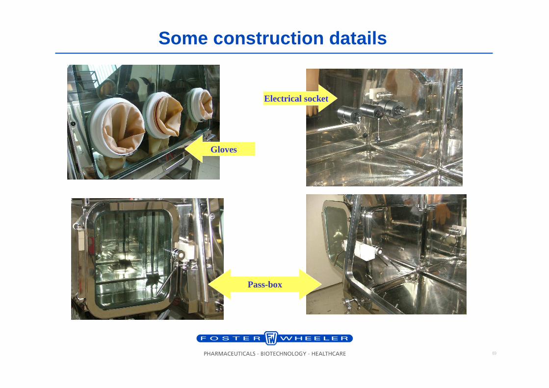
69
Some construction datails
Pass-box
Electrical socket
Gloves
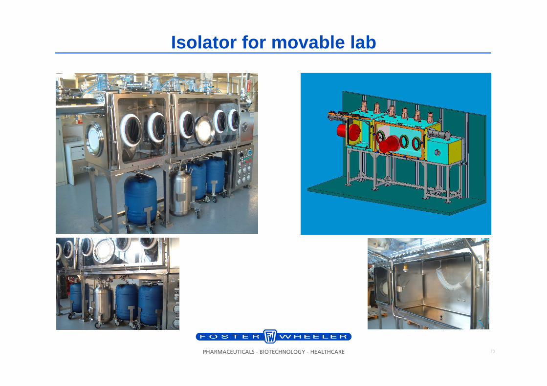
70
Isolator for movable lab
71
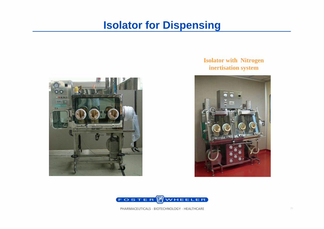
Isolator for Dispensing
Isolator with Nitrogen inertisation system
72
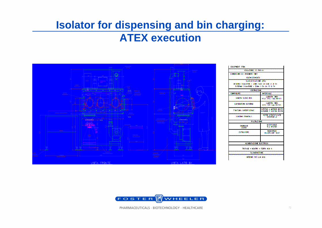
Isolator for dispensing and bin charging: ATEX execution


