Advanced Steel Construction Vol. 3, No. 4, pp. 737-751 (2007) 737 DESIGN OF CORRUGATED WEBS UNDER PATCH LOAD Krzysztof R. Kuchta Ph. D., Faculty of Civil Engineering, Cracow University of Technology ul. Warszawska 24, 31-155 Cracow, Poland * (Corresponding author: E-mail: [email protected]) Received: 19 October 2006; Revised: 2 May 2007; Accepted: 13 June 2007 ABSTRACT: Corrugated webs, in spite of their small thickness, are characterized by relatively high patch load carrying capacity. Some formulae for estimating patch load carrying capacity can be found in specialist literature. They were derived from different web failure mechanical models and values of patch load carrying capacity calculated from these formulae differ from one to another. Shaping of web folds in form of sinusoidal wave cause increase of web patch load carrying capacity in comparison with web with other shapes of folds. In experimental tests and numerical simulations it has been shown that, as well as in plate webs, in corrugated webs their patch load carrying capacity is dependent on the width of patch load application. Keywords: Ultimate strength; thin-walled structures; corrugated web; patch load 1. INTRODUCTION Web of optimally shaped classical bended steel plate girder includes about 50% of the material and carries shear force and only 15% of bending moment. For this reason possibility of using slender webs in order to decrease share of web weight in plate girder total weight was researched for a long time. The idea of applying thin corrugated sheet for plate girder web appeared in the 30s of 20 th century, but the high cost of welds between web and flange made the construction of this kind of profiles uncommon. The situation changed in the end of the 80s of 20 th century when the automatical flange to web welding process line made the production of a new generation of steel girders with corrugated web possible. These girders consist of flanges made of hot-rolled plates (in general from steel of higher strength) and webs made of sinusoidally profiled sheets (in general from steel of lower strength). Figure 1 Automatic Welding of Web to Flanges of the Girder
Transcript
Advanced Steel Construction Vol. 3, No. 4, pp. 737-751 (2007) 737
DESIGN OF CORRUGATED WEBS UNDER PATCH LOAD
Krzysztof R. Kuchta
Ph. D., Faculty of Civil Engineering, Cracow University of Technology ul. Warszawska 24, 31-155 Cracow, Poland
Received: 19 October 2006; Revised: 2 May 2007; Accepted: 13 June 2007
ABSTRACT: Corrugated webs, in spite of their small thickness, are characterized by relatively high patch load carrying capacity. Some formulae for estimating patch load carrying capacity can be found in specialist literature. They were derived from different web failure mechanical models and values of patch load carrying capacity calculated from these formulae differ from one to another. Shaping of web folds in form of sinusoidal wave cause increase of web patch load carrying capacity in comparison with web with other shapes of folds. In experimental tests and numerical simulations it has been shown that, as well as in plate webs, in corrugated webs their patch load carrying capacity is dependent on the width of patch load application.
1. INTRODUCTION Web of optimally shaped classical bended steel plate girder includes about 50% of the material and carries shear force and only 15% of bending moment. For this reason possibility of using slender webs in order to decrease share of web weight in plate girder total weight was researched for a long time. The idea of applying thin corrugated sheet for plate girder web appeared in the 30s of 20th century, but the high cost of welds between web and flange made the construction of this kind of profiles uncommon. The situation changed in the end of the 80s of 20th century when the automatical flange to web welding process line made the production of a new generation of steel girders with corrugated web possible. These girders consist of flanges made of hot-rolled plates (in general from steel of higher strength) and webs made of sinusoidally profiled sheets (in general from steel of lower strength).
Figure 1 Automatic Welding of Web to Flanges of the Girder
738 Design of Corrugated Webs under Patch Load
Geometrical parameters of web waves are selected in such a way that web instability does not occur before shear stresses reach yield point. Flanges of this web thickness do not exceed 3 mm even with web depth equal to 1500 mm. In comparison to girders with plate web proportion of mass distribution is changed (see Figure 2).
Figure 2 Mass Distribution in Girders with Plane and Corrugated Web
Moving of part of the web mass into flanges makes the girder with corrugated web 30% lighter than girder with plate web with the same elastic load capacity. Girders with corrugated web are mainly used in one-floor halls with light roof and walls covering (Figure 3).
Figure 3 Industrial Hall Made of Girders with Corrugated Web
One of the advantages of girders with corrugated web is that no web stiffeners are needed (with the exception of locations under large concentrated forces, for example, over supports). The problem of proper determination of unstiffened web carrying capacity under patch load is of great practical importance, because stiffeners are hand-welded with considerable increase in costs of construction. In the case when patch load must be transferred to upper flange of the girder, designer may not use the stiffeners under this load, provided that condition of patch load carrying capacity of the web is fulfilled. Additionally, if in the considered cross section both bending moment and shear force are large in comparison with the appropriate carrying capacities, interaction of patch load and compressing force from bending in flanges must be taken into consideration.
Krzysztof R. Kuchta 739
2. DESIGN FORMULAE OF CORRUGATED WEBS UNDER PATCH LOAD According to Eurocode 3 [1] in case of unstiffened webs of welded girders, loaded in their own plane by patch load, three forms of failure may occur: (1) plastification of the web in the contact zone near the flange, (2) web crippling – local elastic-plastic instability of the web involved in plastic deformations of
the loaded flange, (3) web buckling on the major part of the web depth. Large moment of inertia of corrugated web in direction perpendicular to wave generator leads to one third of the above mentioned forms of failure in this type of girder practically non-existent. Taking into consideration the first form of failure design patch load carrying capacity of a plane web may be described as follows dwRd ftcP ⋅⋅= 0 , (1) ( )atkcc f +⋅+=0 , (2) where: c0 – effective width of patch load distribution on the web,
c – width of patch load application on the girder flange, k – coefficient depending on deformability of loading element (k = 2 - 5), tf – thickness of loaded flange, a – thickness of weld connecting web with flange, tw – web thickness, fd – design resistance of web steel.
Patch load carrying capacity of corrugated web may be calculated from (1) with effective width of applied load equal to wave development length on segment c0 according to (2) (Siokola [2]). This method gives safe, but overestimated (even more than 200%), values of patch load carrying capacity of corrugated web, what has been confirmed by experimental tests (Ramberger [3], Pasternak and Brańka [4], Kuchta [5]). If loading element is stiff and insensitive to deformations, effective width of patch load distribution on the web c0 can be written in the following form (Broude [6]):
ctI
cw
xf +⋅= 30 η , (3)
where: η – dimensionless coefficient depending on web to flange clamping rigidity (for welded
girders η = 3,26), Ixf –moment of inertia of loaded flange.
Determination of patch load carrying capacity of corrugated web according to (1) with effective width of patch load distribution on the web c0 according to (3) (assuming η = 3,75 as for riveted girders) gives safe load close to experimental tests (Kuchta [5]). It must be noticed that this is only
740 Design of Corrugated Webs under Patch Load
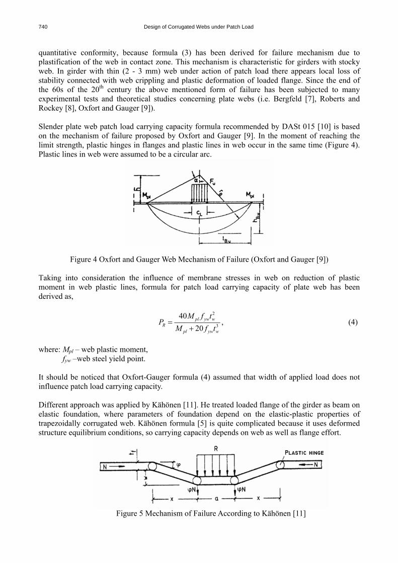
quantitative conformity, because formula (3) has been derived for failure mechanism due to plastification of the web in contact zone. This mechanism is characteristic for girders with stocky web. In girder with thin (2 - 3 mm) web under action of patch load there appears local loss of stability connected with web crippling and plastic deformation of loaded flange. Since the end of the 60s of the 20th century the above mentioned form of failure has been subjected to many experimental tests and theoretical studies concerning plate webs (i.e. Bergfeld [7], Roberts and Rockey [8], Oxfort and Gauger [9]). Slender plate web patch load carrying capacity formula recommended by DASt 015 [10] is based on the mechanism of failure proposed by Oxfort and Gauger [9]. In the moment of reaching the limit strength, plastic hinges in flanges and plastic lines in web occur in the same time (Figure 4). Plastic lines in web were assumed to be a circular arc.
Figure 4 Oxfort and Gauger Web Mechanism of Failure (Oxfort and Gauger [9]) Taking into consideration the influence of membrane stresses in web on reduction of plastic moment in web plastic lines, formula for patch load carrying capacity of plate web has been derived as,
2
3
4020pl yw w
Rpl yw w
M f tP
M f t=
+, (4)
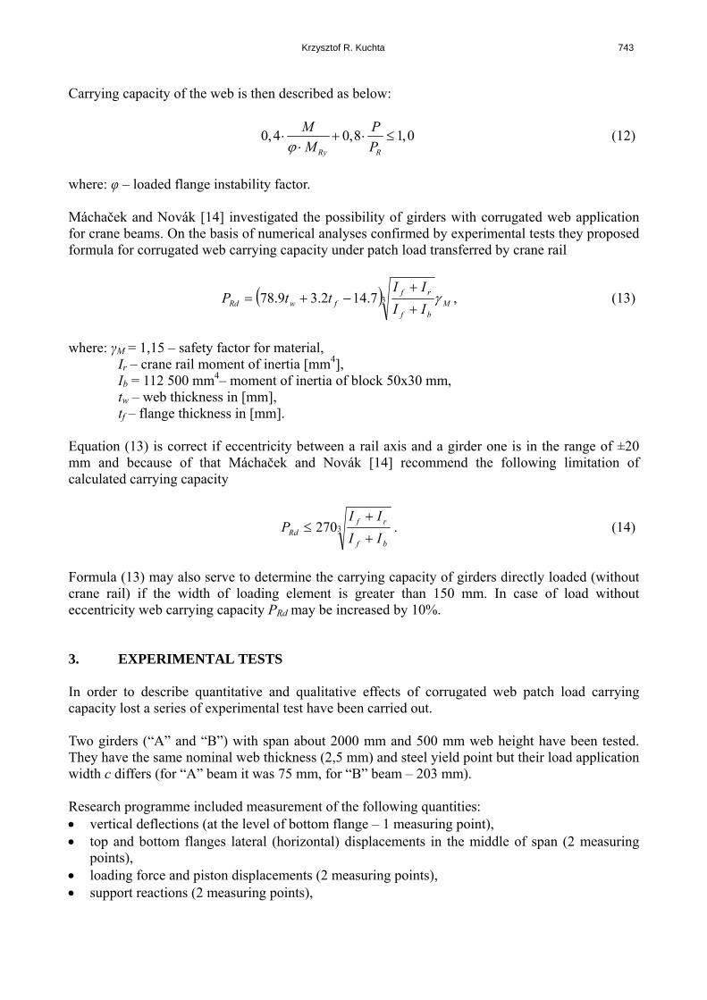
where: Mpl – web plastic moment, fyw –web steel yield point. It should be noticed that Oxfort-Gauger formula (4) assumed that width of applied load does not influence patch load carrying capacity. Different approach was applied by Kähönen [11]. He treated loaded flange of the girder as beam on elastic foundation, where parameters of foundation depend on the elastic-plastic properties of trapezoidally corrugated web. Kähönen formula [5] is quite complicated because it uses deformed structure equilibrium conditions, so carrying capacity depends on web as well as flange effort.
Figure 5 Mechanism of Failure According to Kähönen [11]
Krzysztof R. Kuchta 741
Patch load design carrying capacity of corrugated web according to Kähönen [11] has the following form
( ) 01 2 3
rRd d d d
M
k kP R R Rγ
= + + , (5)
where: Rd1 – web reaction force,
Rd2 – additional force due to flange bending moment carrying capacity, Rd3 – force increasing pressure due to normal force acting in flange (see Figure 5), γM – safety factor for material, kr, k0 – dimensionless corrective factors.
Equation (5) depends on many design variables and empirical factors and therefore is not convenient in design practice. Exact description of parameters in Equation (5) can be found in Kähönen [11]. Luo and Edlund ([12] and [13]) in their numerical analyses proved that patch load carrying capacity of corrugated web strongly depends on the width of applying load (see Figure 6).
Figure 6 Equilibrium Paths of Girder with Different Width of Applied Load
(Luo and Edlund [12]) On the basis of the obtained analysis results, they proposed the following empirical formula for carrying capacity of trapezoidally corrugated web under patch load. R f w ywP t t fγ= , (6) 15,6 cαγ γ γ= , (7) where: γ – coefficient depending on geometrical parameters of the fold and load application width,
742 Design of Corrugated Webs under Patch Load
( )
82,3 when
82,3 when
1
cos31
31
<
≥
⎪⎪⎩
⎪⎪⎨
⎧α+
+
=γα
w
f
w
f
tt
tt
aaaa
(8)
1240c
cγ = + , (9)
a1 – length of the fold panel parallel to the web, a3 – length of fold oblique panel projection on girder axis, α – inclination angle of oblique panel of the fold, c – load application width [mm]. Formula (6) is valid for 75α ≤ o .
In case of girders with sinusoidally corrugated web successfully attempt at solving problem of web patch load carrying capacity was taken in 1999 by Pasternak and Brańka [4]. They carried out a series of experimental tests and numerical analyses investigating the influence of geometrical parameters of girder with sinusoidally corrugated web on patch load carrying capacities. It was affirmed that load application width and load location in relation to characteristic points of the web wave (crest, zero point) have no significant influence on patch load carrying capacity of corrugated web. It was also shown that web and flange thickness have great influence on studied carrying capacity. The following formula of corrugated web patch load carrying capacity was proposed
dw
,
wyw
xfRd ftf
t/IW
P ⋅⋅⋅⋅⎟⎟⎠
⎞⎜⎜⎝
⎛⋅= 210
40
, (10)
where: Wxf – loaded flange section modulus,
Iyw – single wave moment of inertia in relation to beam axis, f – wave amplitude (height).
Equation (10) does not take into consideration load application width which, in case of relatively large widths, may lead to underestimating of patch load carrying capacity. This conclusion was confirmed by the results of author’s experimental tests (Kuchta [5]). According to Pasternak and Brańka [4] if patch load is acting in place of large bending moment, interaction of patch load and bending moment should be taken into consideration. This case occurs if the following conditions are fulfilled.
0,5 1,0
0,75 1,0
R
Rc
MM
PP
⎧ ≤ ≤⎪⎪⎨⎪ ≤ ≤⎪⎩
(11)
Krzysztof R. Kuchta 743
Carrying capacity of the web is then described as below:
0, 4 0,8 1,0Ry R
M PM Pϕ
⋅ + ⋅ ≤⋅
(12)
where: φ – loaded flange instability factor. Máchaček and Novák [14] investigated the possibility of girders with corrugated web application for crane beams. On the basis of numerical analyses confirmed by experimental tests they proposed formula for corrugated web carrying capacity under patch load transferred by crane rail
( ) Mbf
rffwRd II
IIttP γ37.142.39.78
+
+−+= , (13)
where: γM = 1,15 – safety factor for material, Ir – crane rail moment of inertia [mm4], Ib = 112 500 mm4– moment of inertia of block 50x30 mm, tw – web thickness in [mm], tf – flange thickness in [mm]. Equation (13) is correct if eccentricity between a rail axis and a girder one is in the range of ±20 mm and because of that Máchaček and Novák [14] recommend the following limitation of calculated carrying capacity
3270bf
rfRd II
IIP
+
+≤ . (14)
Formula (13) may also serve to determine the carrying capacity of girders directly loaded (without crane rail) if the width of loading element is greater than 150 mm. In case of load without eccentricity web carrying capacity PRd may be increased by 10%.
3. EXPERIMENTAL TESTS
In order to describe quantitative and qualitative effects of corrugated web patch load carrying capacity lost a series of experimental test have been carried out. Two girders (“A” and “B”) with span about 2000 mm and 500 mm web height have been tested. They have the same nominal web thickness (2,5 mm) and steel yield point but their load application width c differs (for “A” beam it was 75 mm, for “B” beam – 203 mm). Research programme included measurement of the following quantities: • vertical deflections (at the level of bottom flange – 1 measuring point), • top and bottom flanges lateral (horizontal) displacements in the middle of span (2 measuring
points), • loading force and piston displacements (2 measuring points), • support reactions (2 measuring points),
744 Design of Corrugated Webs under Patch Load
• web strains in direction parallel to web generator line in stresses due to patch load acting influence area (9 measuring points),
• supports vertical displacements (2 measuring points). The girders had “fork” supports against rotation on the bearings, patch load was applied in the middle of the span with load application width c. For ease of construction reason the places where the forces were put to girders, were not restrained against the horizontal displacements, but the increase of these displacements was continuously controlled. In the whole range of load, before the limit point on experimental equilibrium path was reached, only quite small horizontal displacements with linear dependence on load were observed. It means that during the whole experiment pure form of bending was maintained. Small span girder allows almost complete elimination of bending moment influence on web in support of patch load. The main element of the test stand was a frame with SCHENCK hydraulic jack. The loads were controlled by displacements, what allows very accurate determination of ultimate carrying capacity and observation of post-limit states girder behaviour. Load was increased in steps, the length of step was lessened along with approaching predicted girder carrying capacity. Periods of stabilization, as well as periods of changes in acting load, were increased with girder deflection. During the tests cycles of “loading-unloading”, the values of permanent deflections are in control. Experimental equilibrium paths of tested girders are presented in Figures 7 and 8.
Figure 7 Experimental Equilibrium Path of Girder “A”
Krzysztof R. Kuchta 745
Figure 8 Experimental Equilibrium Path of Girder “B”
Because of girder small span its deflections (without supports settlement) were not large and in the range of 1,78 to 2,50 mm for force equal to limit point Pgr. For this reason, in range of loading force about 0 – 0,4 Pgr, strong influence of test stand mechanical elements with unavoidable imperfections on the course of equilibrium path was observed (see Figures 7 and 8). Flexibility of supports, deformability of dynamometers measurement system, bearing and clamping clearances caused some irregularities, and it even increases stiffness in the girder resistance at early stages. When applied load exceeded the value around 0,7Pgr nonlinearity of equilibrium paths occurred. Further loading to Pgr, there occurred a sudden loss of stability due to web plastic line, parallel to flanges axis but not exceeding web wave length. In each case propagation of web plastic line was limited to the nearest crest of wave. In Figures 9 and 10 forms of failure for web and flange of girders “A” and “B” are presented.
Figure 9 Form of Failure for Web and Flange of Girder “A”
746 Design of Corrugated Webs under Patch Load
Figure 10 Form of Failure for Web and Flange of Girder “B” It should be noticed that girders “A” and “B”, differing from each other only in load application width c, reached significantly different values of load corresponding to limit point on equilibrium path (for girder “A” Pgr = 169,9 kN, for girder “B” Pgr = 246,3 kN). Results of conducted experimental test showed that, similarly as for girders with plate web, patch load carrying capacity of girders with corrugated web is strongly dependent on load application width. 4. NUMERICAL SIMULATIONS Ultimate strength of steel girders with corrugated web under patch loading was studied using a non-linear finite element method. Throughout the studies girders were described by shell model with geometry given in Figure 11.
Figure 11 Static System of Shell Model of Tested Girders Component shells of the model were located at flanges and web central surface. Web surface was modeled as waved surface with generating line perpendicular to flanges surface and direction described by sinusoid equation.
Krzysztof R. Kuchta 747
⎟⎟⎠
⎞⎜⎜⎝
⎛⋅⋅
⋅=qxfxz
5,0sin)( π . (15)
For the numerical studies a finite element program ANSYS 8.0 was used. Effect of large deflections was taken into account and elastic-plastic model of material with strain hardening coefficient (1/10000) E (E = 205 GPa) was assumed. Throughout the simulations, a 4-node quadrilateral shell element SHELL43 was utilized to mesh both web and flanges. In place of support reactions acting 10 mm thick stiffeners were inserted. In order to achieve the best conformity between experimental tests conditions and numerical simulations, the model of the girder was supplemented with the model of distance piece meshed by 8-node brick elements SOLID45. Inserting this distance piece allowed to eliminate loaded flange bending in plane perpendicular to its axis. A layer of contact elements CONTAC52 was placed between flange and distance piece surfaces what enables local “unsticking” of contact surfaces and redistribution of contact stresses.
Figure 12 First Eigenvector Displacements uz [m] for Model of Girder “A” The influence of geometric imperfections and fields of residual stresses were taken into consideration by means of introducing equivalent effective geometric imperfection in the form of 1st eigenvector obtained as a result of solving linear stability eigenproblem by the linearized stability equation (Figure 12). On the basis of a series of numerical simulations it was established that, in considered case, effective imperfection amplitude may be equal to thickness of the web. Nonlinear static analysis which took into consideration large strains, large deflections and their gradients was performed for the above mentioned girder model. Arc-length method was used for solving nonlinear equations system, which allowed the attainment of the limit point in tracing of equilibrium path and allowed the studies of the behaviour of deflection in post-limit states. Numerical equilibrium paths of girders “A” and “B” are presented in Figures 13 and 14, respectively.
748 Design of Corrugated Webs under Patch Load
Figure 13 Comparison of Experimental and Numerical Equilibrium Paths of Girder “A”
Figure 14 Comparison of Experimental and Numerical Equilibrium Paths of Girder “B” In both cases good conformity between experimental and numerical equilibrium paths was obtained. In Table 1 values of load patch carrying capacity determined from theoretical formulae, obtained from experimental tests and numerical simulations are compared. It should be noticed that among theoretical formulae surprisingly good conformity with test results for both girders shows formula (1) with effective width of patch load distribution on the web c0 according to (3).
Krzysztof R. Kuchta 749
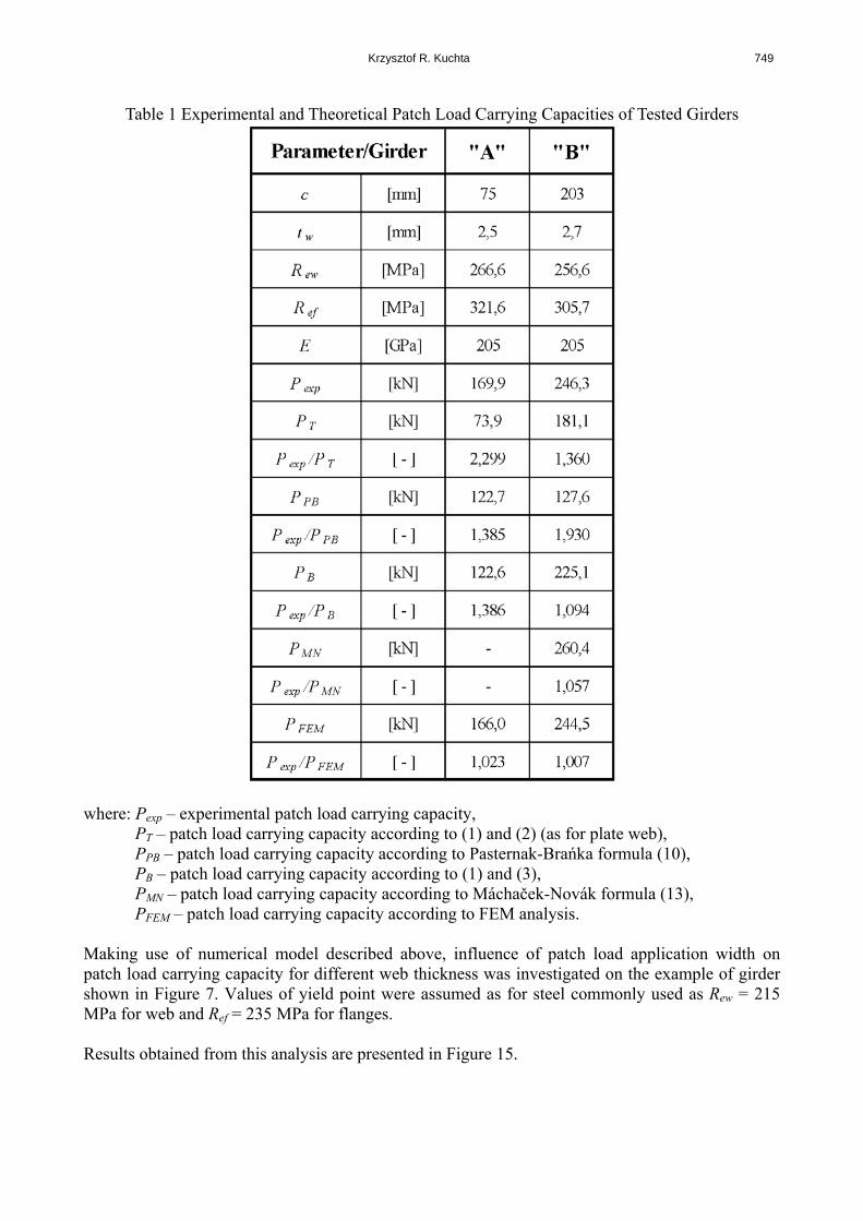
Table 1 Experimental and Theoretical Patch Load Carrying Capacities of Tested Girders
PT – patch load carrying capacity according to (1) and (2) (as for plate web), PPB – patch load carrying capacity according to Pasternak-Brańka formula (10), PB – patch load carrying capacity according to (1) and (3), PMN – patch load carrying capacity according to Máchaček-Novák formula (13), PFEM – patch load carrying capacity according to FEM analysis.
Making use of numerical model described above, influence of patch load application width on patch load carrying capacity for different web thickness was investigated on the example of girder shown in Figure 7. Values of yield point were assumed as for steel commonly used as Rew = 215 MPa for web and Ref = 235 MPa for flanges. Results obtained from this analysis are presented in Figure 15.
750 Design of Corrugated Webs under Patch Load
Figure 15 Influence of Patch Load Application Width on Ultimate Strength of Corrugated Web
5. CONCLUSIONS The results of experimental tests and numerical studies are presented and it can be seen that, for girders with plane web, patch load capacity for girders with corrugated web depends heavily on patch load application width. From the numerical results, the girder ultimate strength depends linearly on patch load application width. Increase in girder ultimate strength due to larger patch load application width is more significant for thicker webs. Problems of patch load carrying capacity of corrugated web need further investigations in order to realize its dependence on other design variables such as girder geometrical dimensions and internal forces distribution. REFERENCES [1] Eurocode No. 3, Design of Steel Structure. Part 1.1. General rules and rules for buildings
(European Prestandard ENV-1993-1-1). [2] Siokola, W., “Wellstegträger. Herstellung und Anwendung von Trägern mit profiliertem
Steg“, Stahlbau 9/1997, pp. 596-605. [3] Ramberger, G., “Gutachten über die Berechnung von Geschweissten I-Trägern Mit Stegen
Aus Gewellten Blechen“, O. Univ., Wien 1989 – not published. [4] Pasternak, H. and Brańka, P., “Tragverhalten von Wellstegträgern unter lokaler
Lasteinleitung“, Bauingenieur 5/1999, pp. 219-224. [5] Kuchta, K.R., ”Nośność i Sztywność Blachownic o Falistych środnikach”, Politechnika
Krakowska, Kraków 2004. [6] Broude, B.M., ”Raspriedielienie Sosriedotocziennowo Dawlienia W Mietaliczeskich
Bałkach”, Strojizdat, Moskwa – Leningrad 1950. [7] Bergfelt, A., “Studies and Tests on Slender Plate Girders without Stiffeners”, IABSE Coll.
Des. Plate Box Girders Ultimate Strenght, London 1971. [8] Roberts, T.M. and Rockey, K.C., “A Mechanism Solution for Predicting the Collapse Loads
of Slender Plate Girders when Subjected to In-Plane Patch Loading”, Proceedings of Institution of Civil Engineers, Part 2, 1979, pp. 155-175.
Krzysztof R. Kuchta 751
[9] Oxfort, J. and Gauger, H.U., “Beultraglast von Vollwandträgern unter Einzellasten“, Stahlbau, 11/1989, pp. 331-339.
[10] DASt-Richtlinie 015. Träger mit Schlanken Stegen, Deutsches Ausschuss für Stahlbau, DASt, Köln, 1990.
[11] Kähönen A., “Zur Einleitung von Einzellasten in I-Träger mit trapezförmig profilierten Stegen“, Stahlbau, 57/1988, pp. 250-252.
[12] Luo, R. and Edlund, B., “Strength of Plate Girders with Trapezoidally Corrugated Webs in Shear or under Patch Loading”, Proceedings of Nordic Steel Construction Conference, Malmö, 1995, pp. 79-86.
[13] Luo, R. and Edlund, B., “Shear Capacity of Plate Girders with Trapezoidally Corrugated Webs”, Thin-Walled Structures, 1996, Vol. 26, No. 1, pp. 19-44.
[14] Macháček, J. and Novák, R., “Design Resistance of Undulating Webs under Patch Loading”, Proceedings of the 3rd International Conference Coupled Instabilities in Metal Structures CISM’2000, Lisbon 2000, pp. 371-378.