Design of Guaranteed Safe Maneuvers Using Reachable Sets:Autonomous Quadrotor Aerobatics in Theory and Practice∗
Jeremy H. Gillula†, Haomiao Huang†, Michael P. Vitus†, and Claire J. Tomlin
Abstract— For many applications, the control of a complexnonlinear system can be made easier by modeling the systemas a collection of simplified hybrid modes, each representing aparticular operating regime. An example of this is the decom-position of complex aerobatic flights into sequences of discretemaneuvers, an approach that has proven very successful forboth human piloted and autonomously controlled aircraft.However, a critical step when designing such control systems isto ensure the safety and feasibility of transitions between thesemaneuvers. This work presents a hybrid dynamics frameworkfor the design of guaranteed safe switching regions and isapplied to a quadrotor helicopter performing an autonomousbackflip. The regions are constructed using reachable setscalculated via a Hamilton-Jacobi differential game formulation,and experimental results are presented from flight tests on theSTARMAC quadrotor platform.
I. INTRODUCTIONModern robotic systems are growing ever more capable
and complex. In particular, as UAVs grow in power andmaneuverability they require increasingly sophisticated con-trol systems to take advantage of the full range of theircapabilities. In the development of these control systems, itis often difficult if not impossible to consider a full nonlinearmodel of the system. Many approaches to the control ofhighly maneuverable aircraft have used statistical learningtechniques, for example by copying an expert pilot’s exampletrajectory either through machine learning or via manualcreation of approximate trajectories [2], [3]. These methodshave been able to push the envelope of what is possiblewith autonomous control, but since they lack performanceguarantees about their stability and robustness, their use maybe limited in situations where safety is critical.
An alternative approach that allows more rigorous formalanalysis is hybrid decomposition, where the behavior ofthe system of interest is approximated as a discrete set ofsimpler modes representing the dynamics in specific regimesor portions of the state space. The decomposed hybrid model(consisting of continuous states and discrete states represent-ing the modes of the system) is then used for analysis andcontrol. This approach has proven successful in a variety of
J. Gillula is a Ph.D. Candidate in Computer Science, Stanford University,Stanford, CA 94305, USA [email protected]
H. Huang is a Ph.D. Candidate in Aeronautics and Astronautics, StanfordUniversity, Stanford, CA 94305, USA [email protected]
M. Vitus is a Ph.D. Candidate in Aeronautics and Astronautics, StanfordUniversity, Stanford, CA 94305, USA [email protected]
C. Tomlin is a Professor of Electrical Engineering andComputer Sciences, UC Berkeley, Berkeley, CA 94720, [email protected]†These authors contributed equally to this work.∗An earlier version of this paper, with preliminary reachable set calcu-
lations and simulation results, was presented at ISRR 2009 [1].
Fig. 1. STARMAC quadrotor performing an autonomous backflip maneu-ver.
applications, including manipulator motion planning [4], [5],specifications for mobile robot behaviors [6], and aircraft tra-jectory planning, where complex trajectories were designedby building up sequences of discrete maneuvers [7].
An important consideration in the design and control ofsystems with switched dynamics is the safety of transitionsbetween modes. For example, in the case of aircraft ma-neuver sequences it is necessary to ensure that an aircraftcompleting one maneuver is able to begin the next maneuverwithout being in an unsafe or infeasible configuration. Inthe work described above, this has been accomplished ina variety of ways. The helicopter maneuvering work used“trim states” such as steady flight or hover that the ve-hicle had to return to after a maneuver before beginninganother [7], while the manipulator work has used sequencesof specially derived Lyapunov functions to guarantee thata defined sequence could be followed [5] or analyticallycalculated regions where a given motion was guaranteed toplace a part in a desired configuration [4]. There has alsobeen extensive work in the Hybrid Systems literature onconstruction of switching regions for mode switching [8]–[10], where partitions or manifolds in the state space werefound that are regions of attraction for particular modesor controllers. Much of this work, though, has focused onswitching under nominal conditions or sensing uncertaintyand do not explicitly consider external disturbances.
This paper introduces a novel method for the design ofprovably safe aerobatic maneuvers using hybrid dynamicsand reachability tools in the presence of external distur-bances. This method is applied to a quadrotor helicopterperforming a backflip, where the backflip maneuver is brokeninto three main stages: impulse, drift, and recovery. Theimpulse mode initializes the rotation of the vehicle. Uponreaching the appropriate switching condition the motors are
2010 IEEE International Conference on Robotics and AutomationAnchorage Convention DistrictMay 3-8, 2010, Anchorage, Alaska, USA
turned off for the drift mode, where the vehicle freely rotatesand falls under gravity. Finally, the recovery mode brings thevehicle to a controlled hover condition. Provably safe switch-ing conditions on altitude, altitude rate, attitude, and attituderate are generated using a Hamilton-Jacobi differential gameformulation that guarantees the vehicle will successfully passthrough all three modes to arrive at a desired final state.Controlled backflips were successfully performed using theseswitching rules on the Stanford Testbed of AutonomousRotorcraft for Multi-Agent Control (STARMAC) [11] andresults from these flight tests are presented.
The use of a Hamilton-Jacobi game formulation is apromising tool for the design and verification of safe ma-neuver sequences. By constructing the reachability problemas a game between a disturbance and control, backwardsreachable sets can be calculated where a given controlleris guaranteed to either keep out of or arrive into a definedregion of the state space within some time horizon [12]. Thisformulation was first used to derive guaranteed safe switch-ing regions for a collision avoidance controller for mannedaircraft, where an evader aircraft could be guaranteed tokeep some distance away from a pursuer, but has since beengeneralized to a wide range of systems [13], [14].
The organization of this paper is as follows. Section IIdiscusses the background for the Hamilton-Jacobi differentialgame formulation for robust reachability, and the use ofreachability for maneuver sequencing and design is presentedin Section III. Flight test results are presented in Section IV,with conclusions and future work in Section V.
II. REACHABILITY FOR MODE SWITCHINGThe concept of backwards reachability is used in this work
as a means of generating guaranteed safe sets for modetransitions. For any mode i, the system evolves under thedynamics x = fi(t, x, u, d), where x is the system state, uis the control input, and d is the disturbance input, where uand d are constrained in some sets U and D, respectively.
A. Hamilton-Jacobi ReachabilityA backwards reachable set Preτ (K) is defined as the set
of all states where the system can arrive in some set K withintime τ , under some appropriate set of assumptions aboutthe disturbance and control. Two conditions are consideredhere: safety, where the goal of the control is to stay out ofan undesired set in the state space which the disturbanceis trying to force the system into, and attainability, wherethe goal is to reach a desired set while the disturbance triesto keep the system out of this set. The reachable sets inthis work are calculated using the technique described inMitchell et al. with some modifications [12]. In this method,the reachability problem is posed as a differential gamebetween the control input and disturbance under which thedisturbance chooses the worst-case inputs to either drive thesystem into the undesired set or away from the desired, setand the control does the opposite.
1) Unsafe Sets for Safety: For safety, the goal is tokeep the system’s state out of some undesired set, and thedisturbance is assumed to be attempting to drive the system
into this unsafe set. The unsafe set relative to the keep-out set K for some time τ is denoted Preτ (K), and isdefined as the region of the state space where, for any controlinputs u(t) ∈ U , there exists some sequence of disturbancesd(t) ∈ D such that x(t) ∈ K for some t ∈ [−τ, 0]. That is,if x(−τ) ∈ Preτ (K), then no matter what the control doesthe disturbance can drive the system into K in time less thanor equal to τ . Conversely, if the initial state x(−τ) is outsideof Preτ (K), then there exists a control u(t) that keeps thesystem out of K for up to time τ .
In the game formulation, the boundary of the initial set Kis defined as the zero level set of an appropriately selectedcost function l(x) that is negative inside K and positiveoutside (for an example see Fig. 2). To drive the system intothe undesired set, the disturbance is modeled as attemptingto minimize l(x), while the control attempts to maximizeit. To be conservative, the disturbance is allowed to selectits input after the control input is known. The reachabilitycalculations use a dynamic programming formulation andrequire the optimal Hamiltonian H∗(x, p) for this system,which for a particular mode i is defined as
H∗(x, p) = maxu∈U
mind∈D
pT fi(t, x, u, d) (1)
where p is the Hamiltonian costate.2) Capture Sets for Attainability: Symmetrically, for at-
tainability the desired goal of the controller is to drive thesystem into some desired set D by minimizing the costfunction, while the disturbance is assumed to be attemptingto drive the system away, thereby maximizing the costfunction. Thus a capture set Preτ (D) can be defined for thesystem which guarantees that there exists a control input thatdrives the system into D within time τ no matter what thedisturbance does. This reverses the role of the control anddisturbance, although again for robustness the disturbanceis allowed knowledge of the control input. The optimalHamiltonian in this case is then
H∗(x, p) = minu∈U
maxd∈D
pT fi(t, x, u, d) (2)
3) Reachable Set Calculations: In many cases (such asthe quadrotor maneuvers described below) it can be incon-venient to use the optimal control input described by thedifferential game, and instead a particular pre-determinedcontroller may be used. This is easily accounted for bydefining a controller u = Ci(t, x) specified for the currentlyactive mode. The controller can be subsumed into the mod-ified system dynamics as x = fi(t, x, d) and the optimalHamiltonians for safety and reachability can be modified byremoving the max and min, respectively, over u, and leavingonly the optimization over d.
Once the dynamics, initial set, and defining cost functionare selected, the appropriate Hamiltonian of the system canbe formulated and the backwards reachable sets calculatedusing the Level Set Toolbox developed at the University ofBritish Columbia [15]. Using the given cost function andHamiltonian, the toolbox propagates the boundary of thelevel set describing the initial set of interest (either K or D)
1650
01
23
4
−10
−5
0
5
−4
−2
0
2
4
Attitude RateAttitude
Cost
Fun
ctio
n
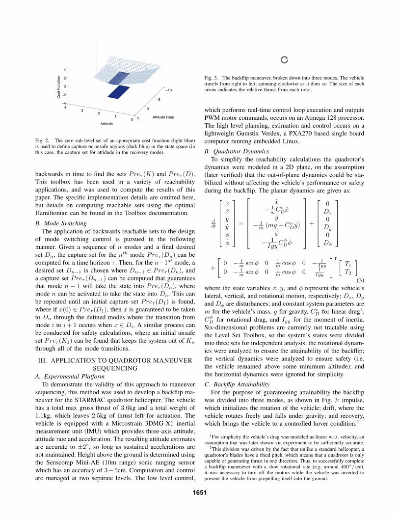
Fig. 2. The zero sub-level set of an appropriate cost function (light blue)is used to define capture or unsafe regions (dark blue) in the state space (inthis case, the capture set for attidude in the recovery mode).
backwards in time to find the sets Preτ (K) and Preτ (D).This toolbox has been used in a variety of reachabilityapplications, and was used to compute the results of thispaper. The specific implementation details are omitted here,but details on computing reachable sets using the optimalHamiltonian can be found in the Toolbox documentation.
B. Mode SwitchingThe application of backwards reachable sets to the design
of mode switching control is pursued in the followingmanner. Given a sequence of n modes and a final desiredset Dn, the capture set for the nth mode Preτ (Dn) can becomputed for a time horizon τ . Then, for the n−1st mode, adesired set Dn−1 is chosen where Dn−1 ∈ Preτ (Dn), anda capture set Preτ (Dn−1) can be computed that guaranteesthat mode n − 1 will take the state into Preτ (Dn), wheremode n can be activated to take the state into Dn. This canbe repeated until an initial capture set Preτ (D1) is found,where if x(0) ∈ Preτ (D1), then x is guaranteed to be takento Dn through the defined modes where the transition frommode i to i+ 1 occurs when x ∈ Di. A similar process canbe conducted for safety calculations, where an initial unsafeset Preτ (K1) can be found that keeps the system out of Kn
through all of the mode transitions.
III. APPLICATION TO QUADROTOR MANEUVERSEQUENCING
A. Experimental PlatformTo demonstrate the validity of this approach to maneuver
sequencing, this method was used to develop a backflip ma-neuver for the STARMAC quadrotor helicopter. The vehiclehas a total max gross thrust of 3.6kg and a total weight of1.1kg, which leaves 2.5kg of thrust left for actuation. Thevehicle is equipped with a Microstrain 3DMG-X1 inertialmeasurement unit (IMU) which provides three-axis attitude,attitude rate and acceleration. The resulting attitude estimatesare accurate to ±2◦, so long as sustained accelerations arenot maintained. Height above the ground is determined usingthe Senscomp Mini-AE (10m range) sonic ranging sensorwhich has an accuracy of 3−5cm. Computation and controlare managed at two separate levels. The low level control,
Fig. 3. The backflip maneuver, broken down into three modes. The vehicletravels from right to left, spinning clockwise as it does so. The size of eacharrow indicates the relative thrust from each rotor.
which performs real-time control loop execution and outputsPWM motor commands, occurs on an Atmega 128 processor.The high level planning, estimation and control occurs on alightweight Gumstix Verdex, a PXA270 based single boardcomputer running embedded Linux.
B. Quadrotor DynamicsTo simplify the reachability calculations the quadrotor’s
dynamics were modeled in a 2D plane, on the assumption(later verified) that the out-of-plane dynamics could be sta-bilized without affecting the vehicle’s performance or safetyduring the backflip. The planar dynamics are given as:
ddt
xxyyφ
φ
=
x− 1mC
vDx
y− 1m (mg + CvDy)
φ
− 1IyyC
φDφ
+
0Dx
0Dy
0Dφ
+
[0 − 1
m sinφ 0 1m cosφ 0 − l
Iyy
0 − 1m sinφ 0 1
m cosφ 0 lIyy
]T [T1T2
](3)
where the state variables x, y, and φ represent the vehicle’slateral, vertical, and rotational motion, respectively; Dx, Dy
and Dφ are disturbances; and constant system parameters arem for the vehicle’s mass, g for gravity, CvD for linear drag1,CφD for rotational drag, and Iyy for the moment of inertia.Six-dimensional problems are currently not tractable usingthe Level Set Toolbox, so the system’s states were dividedinto three sets for independent analysis: the rotational dynam-ics were analyzed to ensure the attainability of the backflip;the vertical dynamics were analyzed to ensure safety (i.e.the vehicle remained above some minimum altitude); andthe horizontal dynamics were ignored for simplicity.
C. Backflip AttainabilityFor the purpose of guaranteeing attainability the backflip
was divided into three modes, as shown in Fig. 3: impulse,which initializes the rotation of the vehicle; drift, where thevehicle rotates freely and falls under gravity; and recovery,which brings the vehicle to a controlled hover condition.2
1For simplicity the vehicle’s drag was modeled as linear w.r.t. velocity, anassumption that was later shown via experiment to be sufficiently accurate.
2This division was driven by the fact that unlike a standard helicopter, aquadrotor’s blades have a fixed pitch, which means that a quadrotor is onlycapable of generating thrust in one direction. Thus, to successfully completea backflip maneuever with a slow rotational rate (e.g. around 400◦/sec),it was necessary to turn off the motors while the vehicle was inverted toprevent the vehicle from propelling itself into the ground.
1651
A
B
C
D
F
E
Á
Á0 1 2 3 4 5 6
-8
-6
-4
-2
0
2
Fig. 4. Composite attainable sets of the backflip maneuver are plotted inthe φ (radians) vs φ (radians/second) plane. The backflip maneuver startsin the region labeled F and ends in the region labeled A.
Each mode was designed using the method described inSection II-B. To provide further detail on this process, eachmode is described in reverse order below.
1) Recovery: The final target set for the recovery modewas chosen to be φ = 0± 5◦, φ = 0± 10◦/sec, essentiallya stable hover configuration. As described in Section II-A.3, a fixed controller (in this case a standard PD controlleron φ) was used to drive the vehicle to this configuration.(The control input u was divided between the two motorsas T1 = Tnom − u, T2 = Tnom + u, where Tnom wasthe nominal total thrust necessary to counteract gravity.)This target set was then propagated backwards using theHamilton-Jacobi framework, taking into account the worst-case disturbances due to motor noise and wind. It shouldbe noted that the magnitude of these disturbances has asignificant impact on the resulting reachable sets; as onewould expect, if the potential worst-case disturbances aretoo large, the vehicle may not be able to reach the targetset. For this calculation (and those following) the worst-casedisturbances were determined from previous experience, andwere on the order of 5% of the total nominal thrust necessaryto keep the vehicle aloft. The resulting level set (region Ain Fig. 4) represents the capture set for this maneuver.
2) Drift: For the drift mode the target set was chosen asφ = 110± 20◦, φ = −180± 185◦/sec (region B in Fig. 4),and was again propagated back (this time with no controlinput, and thus reduced worst-case disturbances due to thelack of motor noise) to produce the capture set for the driftmode (region C of Fig. 4).
3) Impulse: Finally, for the impulse mode, the target setwas φ = 310±10◦, φ = −287±58◦/sec (region E of Fig. 4).Once again a fixed controller was used, and the worst-casedisturbances were chosen so as to account for motor noiseand wind. The resulting capture set is pictured in region Fof Fig. 4.
4) Motor Turnoff: Originally, it was assumed that themotors would turn off instantaneously when the vehicleentered the drift mode; that assumption proved to be falseafter some initial experiments. As a result an additional modewas added for the purpose of analysis. In this mode, the
y
y
-2 0 2 4 6 8 10 12 14 16 18-15
-10
-5
0
5
10
15UnsafeRecoveryDrift
Fig. 5. Unsafe vertical sets of the backflip maneuver are plotted in the y(meters) vs y (meters/second) plane. As long as the vehicle begins a givenmode outside that mode’s unsafe set, safety is guaranteed.
motor turn off was modeled as a linear decay in the vehicle’sangular acceleration, i.e.: τ = fsat(αt + φ)/Iyy wherefsat(y) = {y, if y < 0; 0, otherwise}, and the parameterα was found using linear regression. These dynamics werethen propagated forward from the target set of the impulsemode; the resulting level set (pictured in region D of Fig. 4)contains all possible states the vehicle could be in while themotors are turning off. Thus, as long as this set was containedin the drift set, attainability of the backflip was guaranteed.
D. Backflip SafetyTo ensure the vehicle would perform the backflip safely,
a similar procedure to that described for attainability wasused. First, a final unsafe set was chosen to represent allconfigurations the vehicle would need to avoid during therecovery mode. Because the vehicle’s rotational and verticaldynamics are coupled during powered thrust, however, it wasfirst necessary to find a way to decouple them so that safetycould be analyzed solely in the vertical state space. Thisdecoupling was accomplished by taking advantage of the factthat the recovery mode was designed to use a fixed controllaw. As a result, a nominal trajectory could be generated thatcould then be plugged into the system dynamics, allowingthe backwards reachable set to be computed as usual bypropagating it backward for a fixed time Tr, based on themaximum time that the recovery mode could take. Theresulting level set indicates all the configurations in which itwould be unsafe for the vehicle to enter the recovery mode.
In the drift mode the rotational and vertical dynamicsdecouple, and so the unsafe set for the drift mode wasgenerated by propagating backward the unsafe recovery setunder the vertical dynamics. Once again, this was done for afixed time Td, based on the maximum length of the maneuveras calculated from the rotational dynamics. The resultinglevel set represents all the configurations in which it wouldbe unsafe for the vehicle to enter the drift mode.
For the impulse mode it was assumed that there wouldbe no loss in altitude, due to the fact that the impulsemode was designed so that the vehicle’s thrust would alwaysbe upward during this mode. The resulting unsafe sets arepictured in Fig. 5; as long as the vehicle began each modeoutside that mode’s unsafe set, the overall safety of thesystem was guaranteed. To ensure that the vehicle began the
1652
A
B
C
D
F
E
0 1 2 3 4 5 6
-8
-6
-4
-2
0
2
Á
Á
Fig. 6. Three experimental validations (solid, dash and dash-dot lines) ofthe backflip maneuver overlaid on the composite reach sets. The transitionsfrom the impulse to drift mode are shown as black diamonds which arecontained in region E, and the transitions from the drift to the recoverymode are indicated by the black squares that are confined to region B.
entire maneuver outside of these unsafe sets, an additionalpreliminary climb mode was added before the impulse mode,in which the vehicle would accelerate upward until it reacheda safe altitude and velocity.
IV. RESULTSA mosaic of one of the demonstrations of the backflip
maneuver is shown in Fig. 7. Fig. 7(a) depicts the quadrotorafter the initial climb mode which is the start of the impulsemode, and Fig. 7(b) is at the end of the impulse mode andat the beginning of the drift mode. Figs. 7(b)-(f) display theentire drift portion of the maneuver and Fig. 7(e) shows thequadrotor inverted. Finally, Figs. 7(f)-(j) display the recoverymode of the backflip maneuver which successfully returnsthe quadrotor to a safe condition of φ = 0◦ and φ = 0◦/sec.Video of the backflip maneuver can be viewed at http://hybrid.eecs.berkeley.edu/aerobatics.html.
Fig. 6 shows the (φ, φ) trajectory of three experimentalvalidations through the designed attainable sets for the back-flip maneuver. As the figure illustrates, the trajectories arecontained within the capture sets for each maneuver. Thetransition between the impulse and drift modes is denoted bya diamond, and the transition between the drift and recoverymodes is indicated by a square. The switch between themaneuvers are contained within each of their goal regions,E and B, respectively. When the quadrotor switches intothe drift mode, it takes approximately 0.2 seconds for themotors to spin down which explains why the quadrotor is stillaccelerating at the beginning of the drift maneuver. Table Idisplays the time spent in each mode for each trial.
TABLE ITHE AMOUNT OF TIME SPENT IN EACH MODE FOR EACH EXPERIMENTAL
A. Backflip SafetyFig. 8 displays the unsafe vertical reachable sets and the
switching points for the three trials of the maneuver. The bluepoints correspond to entrys into the drift mode and the orangepoints correspond to entry into the recovery mode. As thefigure illustrates, all the points are outside of their respectiveunsafe set and therefore the vehicle can safely perform themaneuver without hitting the ground. Fig. 9 displays that thepitch of the quadrotor is within ±5◦ for almost the entiremaneuver. This validates the assumption that the backflipmaneuver can be modeled in the 2D (φ, φ) plane.
Finally, it should be noted that while the results of onlythree trials are presented here, several additional trials werealso conducted, with varying levels of success. However,these other trials were unsuccessful solely due to factorsoutside the scope of the reachable set analysis. For example,some trials failed because of human error, in the form of bugsin the code running on the vehicle. Others were unsuccessfuldue to hardware malfunctions (e.g. a broken sonic ranger, orsaturation of the IMU’s accelerometers). As every roboticistknows, these sorts of failures are typical when making thetransition from theory to “real” engineering.
V. CONCLUSIONS AND FUTURE WORKReachable set analysis was successfully used to examine
and design an autonomous backflip maneuver. The analy-sis provided a theoretical proof that under the worst casebounded disturbances, which account for modeling errorsand external disturbances such as wind, the quadrotor wouldsafely complete the complicated maneuver. The backflipmaneuver was split into three main stages: impulse, driftand recovery in which switching conditions were providedto ensure a safe transition between the three different modes.The aerobatic maneuver was successfully demonstrated onthe STARMAC quadrotor platform.
The success of several trials coupled with the failure ofothers (due to bugs or hardware malfunctions) emphasizehow useful the presented methodology can be. Becausepractical robotics can be fraught with engineering challengesthat can cause robots to fail, it is all the more important thatas many guarantees as possible about safety be made. While
y
y
-2 0 2 4 6 8 10 12 14 16 18-15
-10
-5
0
5
10
15UnsafeRecoveryDrift
Fig. 8. Three experimental validations (×, +, and •) of the backflipmaneuver. The light blue symbols correspond to the when the vehicleentered into the drift mode and the orange symbols correspond to whenthe vehicle entered into the recovery mode. Since all points are outside oftheir respective reachable set, the vehicle was safe to execute the maneuver.
1653
(a) (b) (c) (d) (e)
(f) (g) (h) (i) (j)Fig. 7. A mosaic of the successful demonstration of the backflip maneuver. (a): The quadrotor has finished the climb portion of the backflip and is startingthe impulse mode. (b): The quadrotor has finished the impulse stage and is entering into the drift portion. (b)-(f): Display of the drift stage of the backflip.(f): The drift mode is concluding and the recovery mode has started. (f)-(j): The recovery mode is safely returning the quadrotor to its hovering position.
0 2 4 6−5
0
5
10
Time (seconds)
Pitc
h (d
egre
es)
Pitch vs Time
Fig. 9. Experimental data from a single run of the backflip maneuvershowing the out-of-plane pitch (degrees) of the quadrotor.
the reachable set framework presented here cannot eliminateall possible failure modes, it can help to ensure that underreasonable circumstances a robot will perform in a provablysafe manner.
There are several possible interesting areas of future work.First, a method of describing the reachable sets in a para-metric way could be explored. In the current framework, theresulting reachable set is greatly dependent on the parametersused when generating it. Consequently, if the parameterschange then the entire reachable set needs to be recalculatedoffline. Second, the reachable set analysis was performedusing a continuous time model, but the implementation ofthe maneuver was performed on a discrete computing plat-form. Therefore, the vehicle may pass through the switchingregions before its controller can change modes. Even thoughthis was not an issue in the experiments that were conducted,it is still an important area of future work.
ACKNOWLEDGMENTSThe authors would like to thank Tony Mercer for his
assistance in performing the flight tests.
REFERENCES
[1] J. H. Gillula, H. Huang, M. P. Vius, and C. J. Tomlin, “Designand analysis of hybrid systems, with applications to robotic aerialvehicles,” in Proceedings of the International Symposium of RoboticsResearch (ISRR), Lucerne, Switzerland, August 2009.
[2] A. Coates, P. Abbeel, and A. Y. Ng, “Apprenticeship learning forhelicopter control,” Commun. ACM, vol. 52, no. 7, pp. 97–105, 2009.
[3] V. Gavrilets, I. Martinos, B. Mettler, and E. Feron, “Flight testand simulation results for an autonomous aerobatic helicopter,” inProceedings of the 21st Digital Avionics Systems Conference, 2002,pp. 8.C.3/1–6, dOI: 10.1109/DASC.2002.1052943.
[4] T. Lozano-Perez, M. T. Mason, and R. H. Taylor, “Automatic Synthesisof Fine-Motion Strategies for Robots,” The International Journal ofRobotics Research, vol. 3, no. 1, pp. 3–24, 1984.
[5] R. Burridge, A. Rizzi, and D. Koditschek, “Sequential compositionof dynamically dexterous robot behaviors,” International Journal ofRobotics Research, vol. 18, no. 6, pp. 534–555, 1999.
[6] H. Kress-Gazit, G. E. Fainekos, and G. J. Pappas, “Translatingstructured english to robot controllers,” Advanced Robotics SpecialIssue on Selected Papers from IROS 2007, vol. 22, no. 12, pp. 1343–1359, 2008.
[7] E. Frazzoli, M. A. Dahleh, and E. Feron, “Maneuver-based motionplanning for nonlinear systems with symmetries,” IEEE Transactionson Robotics, vol. 21, no. 6, pp. 1077–1091, 2005.
[8] M. Zefran and J. W. Burdick, “Stabilization of systems with changingdynamics,” in Hybrid Systems: Computation and Control Conference,Berg en Dal, the Netherlands, 1999.
[9] M. Lazar and A. Jokic, “Synthesis of trajectory-dependent controllyapunov functions by a single linear program,” in Hybrid Systems:Computation and Control Conference, San Francisco, California, 2009.
[10] M. Egerstedt, T. J. Koo, F. Hoffmann, and S. Sastry, “Path planningand flight controller scheduling for an autonomous helicopter,” inHybrid Systems: Computation and Control Conference, Berkeley,California, 1998.
[11] G. M. Hoffmann, H. Huang, S. L. Waslander, and C. J. Tomlin,“Quadrotor helicopter flight dynamics and control: Theory and experi-ment,” in Proceedings of the AIAA Guidance, Navigation, and ControlConference and Exhibit, Hilton Head, SC, August 2007.
[12] I. M. Mitchell, A. M. Bayen, and C. J. Tomlin, “A time-dependenthamilton-jacobi formulation of reachable sets for continuous dynamicgames,” IEEE Transactions on Automatic Control, vol. 50, no. 7, pp.947–957, 2005.
[13] M. Oishi, I. M. Mitchell, A. M. Bayen, and C. J. Tomlin, “Invariance-preserving abstractions of hybrid systems: Application to user interfacedesign,” IEEE Transactions on Control Systems Technology, vol. 16,no. 2, pp. 229–244, 2008.
[14] J. Ding, J. Sprinkle, S. S. Sastry, and C. J. Tomlin, “Reachabilitycalculations for automated aerial refueling,” in Proceedings of the 47thIEEE Conference on Decision and Control, Cancun, Mexico, 2008.
[15] I. Mitchell, A Toolbox of Level Set Methods, 2009, http://people.cs.ubc.ca/∼mitchell/ToolboxLS/index.html.