Design of High Performance Drilling Design of High Performance Drilling Fluids: Challenges And Future Directions for HP/HT Fluids for HP/HT Fluids Apurva Samudra Prof. Nick Sahinidis Kickoff Meeting Energy Systems Initiative (ESI) Energy Systems Initiative (ESI) Center for Advanced Process Decision-making
Transcript
Design of High Performance Drilling Design of High Performance Drilling Fluids: Challenges And Future Directions for HP/HT Fluidsfor HP/HT Fluids
Apurva Samudra
Prof. Nick Sahinidis
Kickoff MeetingEnergy Systems Initiative (ESI) Energy Systems Initiative (ESI)
Center for Advanced Process Decision-making
Deep Drilling
o World energy demand continuously increasing
Total estimated conventional gas resources ato Total estimated conventional gas resources at depths > 4.5 km = 844 TCF
o No. of deep wells disproportionately small compared to their potential
Costs are an order of magnitude higher High costs limit the number of deep wells g p Drilling amounts to 50% of the total well costs Last 10‐20% of the bore hole can account for 50%
of the total cost2
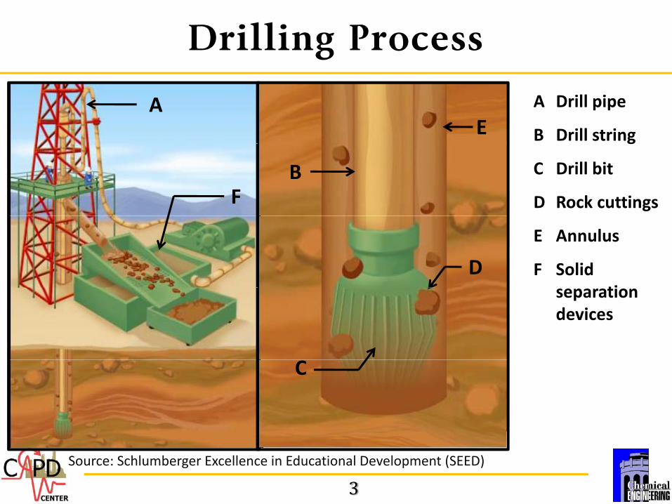
Drilling Process
A Drill pipe
B Drill string
AE g
C Drill bit
D Rock cuttingsFB
E Annulus
F Solid ti
Dseparationdevices
C
3Source: Schlumberger Excellence in Educational Development (SEED)
Drilling Cycle
Drill pipe
i h h
Turbulent zone
i dj d
ill biProperty
o High shear zoneo High temperature
Properties adjusted with additives
Drill bit Property Adjustment
o Laminar flow
Well annulus
Solids control
o Filter‐cake formation
o Cuttings transport
Shale shakers, centrifuges etc. with
Low shear rate
4
o Cuttings transport
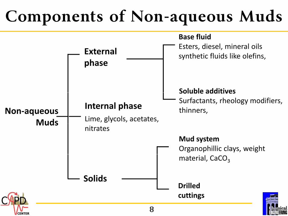
Functions of Drilling Fluids
o Remove and transport drilled cuttings
Removal increases rate of penetration Removal increases rate of penetration
o Cool and lubricate the drill bit
Increase lifespan of the bit
o Seal the wall in permeable formations
Form a filter cake to reduce loss of circulation
o Control pressure in the drilled formationo Control pressure in the drilled formation
Stability and efficiency affected greatly by pressure Manage gas kicks formation liquid invasion etc Manage gas kicks, formation liquid invasion etc.