Design of high-resolution grazing-incidenceechelle monochromators
Luca Poletto* and Fabio FrassettoNational Research Council, National Institute for the Physics of Matter, Laboratory for UVand X-Ray Optical Research and Department of Information Engineering, Padova, Italy
Synchrotron radiation has provided over the pastthirty years an increase in flux and brilliance bymore than ten orders of magnitude in the extreme-ultraviolet (XUV) and x-ray spectral regions, and thishas opened up a fundamentally new area of research[1–5]. The high brilliance of third-generation syn-chrotron sources has lead to a tremendous develop-ment in the design of XUV monochromators. Inparticular, grazing-incidence instruments for highresolution reach resolving power E=ΔE (or equiva-lently λ=Δλ) as high as 100,000 in the XUV, usingplane-grating-monochromator configurations [6,7].High-resolution monochromators are required also
for the upcoming free-electron-laser (FEL) sources.First, they can be used in the users’ beamlines eitherto increase the spectral purity of the FEL emission orto select higher harmonic radiation and filter out themuch more intense fundamental [8]. Second, the useof a high-resolution monochromator placed betweentwo undulators has been proposed to reduce the spec-tral bandwidth of self-amplified spontaneous emis-
sion FELs [9]. Finally, monochromators are abso-lutely necessary for experiments requiring a spectralresolution that is higher than the intrinsic FEL re-solution. In particular, experiments with an unprece-dented resolution in the XUV and x-ray regions willbe made possible by the very high brilliance of FELs.
It is here presented a grazing-incidence configura-tion to achieve high spectral resolution by the use ofgratings in the off-plane mount at high diffracted or-ders. The design is particularly suitable for applica-tions to FEL sources. The main advantages of such aconfiguration are (1) the simplicity of the optical de-sign of the monochromator, since it uses two concavemirrors and a plane grating; (2) the high throughput,due to the intrinsic high efficiency of the off-planemount; (3) the very high spectral resolution in a re-latively compact size; (4) an extended tunability thatis obtained just by changing the operative diffractionorder in the same geometry.
The paper is organized as follows: the configura-tion is presented and discussed in Section 2; the re-sults of ray-tracing simulations are presented inSection 3; the application to a FEL beam with itsunique properties, in particular the high peak power,is finally discussed in Section 4.
2. High-Resolution Monochromator with Gratings inthe Off-Plane Mount
A. Off-Plane Mount
The off-plane mount differs from the classical one inthat the incident and diffracted wave vectors are al-most parallel to the grooves [10]. It has been theoret-ically shown and experimentally measured that thegrating efficiency in the off-plane mount is close tothe reflectivity of the coating, so much higher effi-ciencies than that of the classical mount can be ob-tained in the XUV region [11–16]. Monochromatorswith gratings in the off-plane mount have been re-cently realized for the spectral selection of XUV ul-trashort pulses [17–19].The proposed configuration uses the properties of
the diffraction from a blazed plane grating illumi-nated by a parallel beam in grazing incidence. Thelight approaches the grating in the plane that is par-allel to the direction of the grooves and almost nor-mal to their surface.The geometry of the off-plane mount is shown in
Fig. 1 in a spherical coordinate system. The directionof the incoming rays is described by two parameters,the elevation and the azimuth. The elevation γ is theangle between the direction of the incoming rays andthe direction of the rulings. It defines the half-angleof the cone into which the light is diffracted: all therays leave the grating at the same elevation angle atwhich they approach. The azimuths of the incomingrays α are defined to be zero if they lie on the planenormal to the grating surface and parallel to therulings, so −α is the azimuth of the zero order light.Let β define the azimuth of the diffracted light atwavelength λ and order m. The grating equation iswritten as
sin γðsin αþ sin βÞ ¼ mλσ; ð1Þ
where σ is the grating groove density. The angle γ de-fines the cone of diffraction of the light: diffracted or-
ders of the same wavelength and different wave-lengths lie on a cone whose half-angle is defined byγ. For such a reason, the off-plane mount is alsocalled a conical diffraction mount.
The blaze condition is described as in the classicalcase: the diffraction efficiency is maximized when thediffracted light leaves the grating in such a way thatit performs a specular reflection on the groove sur-face and when the shadowing effects from adjacentgrooves are minimized. The simultaneous fulfillmentof these two requirements gives the condition of op-timal performance of a blaze grating in the off-planemount as α ¼ β ¼ δ, i.e., when each groove of the grat-ing is seen by the incident ray as a portion of a planemirror. The grating equation in the blaze conditionbecomes
2 sin γ sin β ¼ mλσ: ð2Þ
Since the grating is operated in a parallel beam,the configuration requires two additional concavemirrors to collimate the input beam before the grat-ing and to refocus it after the diffraction [20].
The peculiarity of the off-plane mount is thepossibility of operating in the XUVwith conventionalgratings, i.e., σ in the range 1000–2000 grooves=mm,mounted at grazing incidence, i.e., γ in the range2°–15°, at very large diffracted orders, i.e., m > 10.This gives high throughput thanks to the intrinsi-cally high efficiency of the off-plane geometry andhigh resolution in a relatively compact size. Let ussuppose operation at 10nm (124 eV) with elevationγ ¼ 12° and groove density σ ¼ 1200 grooves=mm.The azimuth β calculated from Eq. (3) is shown inFig. 2 for the different diffracted orders; orders uptom ¼ 35 are still diffracted. Clearly, only the ordersthat are diffracted close to the blaze angle δ are mea-surable, the others having efficiency close to zero.Since the azimuth increases with the order, the op-eration at high orders requires large blaze angles.
B. Monochromator in the Off-Plane Mount
The configuration discussed here is schematicallyshown in Fig. 3. It consists of the entrance slit, threeoptical elements (i.e., the two paraboloidal mirrors
Fig. 1. Geometry of the off-plane mount.
Fig. 2. Azimuth angles (in the condition α ¼ β) at the differentdiffracted orders for a 1200grooves=mm grating operated at 12°elevation. The wavelength is 10nm.
M1 andM2 and the plane grating) and the exit slit. Itis here assumed that a prefocusing system creates astigmatic image of the source on the entrance slit ofthe monochromator.Let us indicate as p1 and p2 respectively the dis-
tances between the entrance slit and the center ofmirror M1 and between the center of mirror M2 andthe output slit. The displacement Δl on the exit slitplane corresponding to a wavelength shift Δλ is
Δℓ ¼ Δθ · p2 ¼ mσp2
cos β ·Δλ; ð3Þ
where Δθ is the variation of the direction of thediffracted beam corresponding to the variation Δβof the azimuth angle, i.e., Δθ ¼ sin γ ·Δβ ¼ mσ=cos β ·Δλ.The major effect of the off-plane mount is the
change in the slit shape and orientation due to thehighly nonspecular reflection from the grating [10].Both the distortion and the rotation of the imageafter the diffraction have to be considered to achievehigh spectral resolution.Let us suppose a circular source of diameterD that
in our case is the image of the source created by theprefocusing system on the entrance slit of the mono-chromator. After the diffraction, the diffracted imageis distorted to an ellipse with the major axis inclinedby an angle ϕ with respect to the direction of disper-sion, which is defined as the line tangent to the arc ofcircle that defines the diffraction cone as shown inFig. 4. In the case of grazing incidence, where cos γis close to unity, ϕ is expressed by
ϕ ¼ ðπ=2Þ − β2
: ð4Þ
Thus themajor axis of the ellipse lies along the linethat bisects the angle between the dispersion direc-tion and the normal to the grating surface.Let us define a reference system ðx; yÞ with the two
axes oriented parallel to the axes of the ellipse, xbeing the major axis. If the grating is operated close
to the blaze condition, i.e., β ≈ α, the lengths of theaxes of the ellipse Sx (major axis) and Sy (minor axis)are expressed by
Sx ¼MDcos ρ ; ð5Þ
Sy ¼ MD cos ρ; ð6Þ
where M ¼ p2=p1 is the magnification factor of thetwo mirrors and ρ is defined by the relationtan ρ ¼ 2 tan β cos γ.
In the case of the grazing-incidence echelle config-uration, cos γ is close to unity and β is larger than 40°.In such conditions, Eqs. (5) and (6) simplify as
Sx ≈ MD · 2 tan β; ð7Þ
Sy ≈MD
2 tan β : ð8Þ
Since β ≥ 40°, it is clear that Sx > Sy, since the ra-tio Sx=Sy ¼ 4 tan2β.
In the classical mount, the light is diffracted alonga straight line, and the output slit is normal to thedirection of the spectral dispersion. On the contrary,the off-plane mount gives a dispersion curve that is acircle, so the output slit can be oriented paralleleither to the x or to the y axis. The spectral resolutionis obviously limited by the size of the image on thefocal plane. Having the image as different sizes inthe two directions, the corresponding resolutions willalso be different.
The resolution is here defined when the exit slit isas wide as the diffracted image, i.e., it transmits100% of the flux reflected by the focusing mirror M2.The FWHM resolution is calculated as the spectralshift of the diffracted image as large as the slit width.The resolutions Rx and Ry are calculated fromEqs. (3), (7), and (8) as
Rx ¼λΔλ
����x¼ p1 sin γ × cosϕ
D; ð9Þ
Fig. 3. Schematic of the optical configuration: light entering fromthe entrance slit is collimated by mirror M1, then diffracted by thegrating, then focused by mirror M2 on the exit slit plane. Thewavelength scanning is performed through the grating rotation.
Fig. 4. Distortion of a circular source to an ellipse due to the off-plane grating mount.
where Rx and Ry are defined when the slit is orientedparallel respectively to the y or x axis.The resolution does not depend on the length of the
exit arm of the refocusing mirror p2, but only on thelength of the entrance arm of the collimating mir-ror p1. Ry is higher than Rx, since Ry=Rx ¼4 tanϕ tan2 β > 1. Therefore the resolution is maxi-mized when the slit is oriented parallel to the majoraxis of the elliptical image of the source.The resolution is proportional to sin γ; the higher
the elevation, the higher the resolution at equal azi-muth. Once the spectral region of operation of themonochromator is given, the elevation has to be cho-sen as high as possible to still have good reflectivity.The resolution is also proportional to sinϕ tan2β ¼
2−1=2½cosðβ=2Þ − sinðβ=2Þ�tan2 β, which increases withβ; then the higher the azimuth, the higher the reso-lution at equal elevation.Let us suppose operation with source size D ¼
30 μm (we remark that this is not the physical size ofthe source, but the size of the image created on theentrance slit by the prefocusing system) and en-trance arm p1 ¼ 5m. The resolutions Rx and Ry asa function of γ are shown in Fig. 5. As an example,a grating with groove density σ ¼ 1200 lines=mmoperated at λ ¼ 10nm in the conditions γ ¼ 12°,m ¼ 30, and α ¼ β ¼ 60° gives resolution Ry ≈
107; 000. The size of the exit slit to support such aresolution is calculated from Eq. (8) and dependson the magnification factor of the mirrors: forM ¼ 2:5, i.e., p2 ¼ 12:5m, the exit slit width is22 μm. The total length of the instrument is about18m. In spite of the relatively reduced size, theechelle mount at grazing incidence gives very highXUV spectral resolution in a simple configuration.The use of high diffracted orders reduces the free
spectral range (FSR) of the instrument, here definedas the maximum source bandwidth that gives a puremonochromatic output, i.e., no overlapping of differ-ent wavelengths diffracted at the same azimuth β butat different orders m. Given the wavelength λ dif-fracted at order m, the FSR is inversely proportionalto the diffracted order,
FSR ¼ 2mλm2
− 1≅
2λm
; ð11Þ
where the approximation is for high diffracted orders(m ≥ 5). In the case of a broadband source, such as asynchrotron, the reduced FSR would give at the exitslit of the monochromator a polychromatic output,i.e., λm diffracted at order m, λmþ1 ¼ mλm=ðmþ 1Þ <λm diffracted at order mþ 1, λm−1 ¼ mλm=ðm − 1Þ >λm diffracted at order m − 1, and so on. On the con-trary, the case of a FEL source is different: the nat-ural bandwidth of the FEL emission is of the order of1% for self-amplified spontaneous emission (SASE)operation [21] and even much narrower for seededoperation. Therefore the FSR is larger than theFEL bandwidth, so a real monochromatic output isexpected at orderm without any contamination fromthe different orders.
The wavelength scanning is performed throughthe rotation of the grating around an axis that is par-allel to the grooves and passes though the gratingcenter, so that the variation of the azimuth Δβ isequal to the angle of rotation ΔΦ. The scanning onan extended spectral region requires a large varia-tion of the azimuth following the relation Δβ ¼mσΔλ=ð2 × cos β sin γÞ. Let us take the same para-meters as the example given before, i.e., σ ¼1200 lines=mm, γ ¼ 12°, m ¼ 30; the azimuth is β ¼60° at λ ¼ 10nm and β ¼ 51° at λ ¼ 9nm. The largevariation of the azimuth required to scan the wave-length has two main drawbacks: the drop of the grat-ing efficiency and the variation of the resolution. Infact, once the blaze angle δ has been selected, the con-dition of maximum efficiency is exactly fulfilled onlyat the blaze wavelength λB;m ¼ 2 sin γ sin δ=ðmσÞ. Atdifferent wavelengths, the efficiency at the same or-der m decreases as we go further from the blazecondition [14]. Furthermore, the resolution changeswith the azimuth as the factor sinϕ tan2 β, so thehigher the azimuth, the higher the resolution.
The requirements of maintaining both high effi-ciency and constant resolution within a broad spec-tral interval are fulfilled if the grating is operated atdifferent diffraction orders in different spectral re-gions. For a given order m, the interval of oper-ation is defined as Δλm ¼ ðλB;m−1 − λB;mþ1Þ=2 ≅
2 sin γ sin δ=ðσm2Þ and the corresponding variationof the azimuth around the central value β ¼ δ isΔβm ≅ � tan δ=ð2mÞ. The variations of the azimuthare now less severe (in the few to several degreesrange), since the spectral region to be covered bythe grating rotation is much narrower, and this en-sures high efficiency and almost constant resolutionin the whole region of operation. As an example, letus take the same parameters as before: the spectralregion that is covered at the order m ¼ 30 is Δλ30 ≅
10� 0:17nm with a rotation Δβm ≅ �1:7°. Adjacentregions are covered by operating the grating at thesame elevation but at different orders. For example,the operation at order m ¼ 29 allows spanning overthe region Δλ29 ≅ 10:35� 0:18nm.
Fig. 5. Resolutions Rx and Ry as a function of γ with source sizeD ¼ 30 μm and entrance arm p1 ¼ 5m.
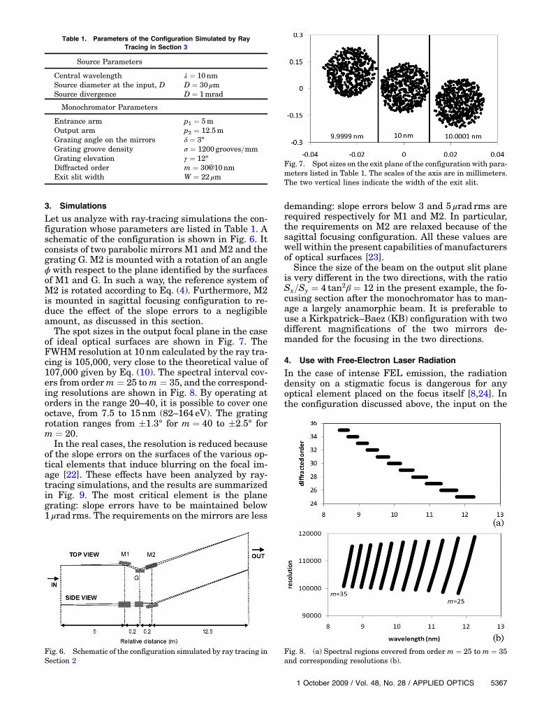
Let us analyze with ray-tracing simulations the con-figuration whose parameters are listed in Table 1. Aschematic of the configuration is shown in Fig. 6. Itconsists of two parabolic mirrors M1 and M2 and thegrating G. M2 is mounted with a rotation of an angleϕ with respect to the plane identified by the surfacesof M1 and G. In such a way, the reference system ofM2 is rotated according to Eq. (4). Furthermore, M2is mounted in sagittal focusing configuration to re-duce the effect of the slope errors to a negligibleamount, as discussed in this section.The spot sizes in the output focal plane in the case
of ideal optical surfaces are shown in Fig. 7. TheFWHM resolution at 10nm calculated by the ray tra-cing is 105,000, very close to the theoretical value of107,000 given by Eq. (10). The spectral interval cov-ers from orderm ¼ 25 tom ¼ 35, and the correspond-ing resolutions are shown in Fig. 8. By operating atorders in the range 20–40, it is possible to cover oneoctave, from 7.5 to 15nm (82–164 eV). The gratingrotation ranges from �1:3° for m ¼ 40 to �2:5° form ¼ 20.In the real cases, the resolution is reduced because
of the slope errors on the surfaces of the various op-tical elements that induce blurring on the focal im-age [22]. These effects have been analyzed by ray-tracing simulations, and the results are summarizedin Fig. 9. The most critical element is the planegrating: slope errors have to be maintained below1 μrad rms. The requirements on the mirrors are less
demanding: slope errors below 3 and 5 μrad rms arerequired respectively for M1 and M2. In particular,the requirements on M2 are relaxed because of thesagittal focusing configuration. All these values arewell within the present capabilities of manufacturersof optical surfaces [23].
Since the size of the beam on the output slit planeis very different in the two directions, with the ratioSx=Sy ¼ 4 tan2β ¼ 12 in the present example, the fo-cusing section after the monochromator has to man-age a largely anamorphic beam. It is preferable touse a Kirkpatrick–Baez (KB) configuration with twodifferent magnifications of the two mirrors de-manded for the focusing in the two directions.
4. Use with Free-Electron Laser Radiation
In the case of intense FEL emission, the radiationdensity on a stigmatic focus is dangerous for anyoptical element placed on the focus itself [8,24]. Inthe configuration discussed above, the input on the
Table 1. Parameters of the Configuration Simulated by RayTracing in Section 3
Source Parameters
Central wavelength λ ¼ 10nmSource diameter at the input, D D ¼ 30 μmSource divergence D ¼ 1mrad
Monochromator Parameters
Entrance arm p1 ¼ 5mOutput arm p2 ¼ 12:5mGrazing angle on the mirrors δ ¼ 3°Grating groove density σ ¼ 1200grooves=mmGrating elevation γ ¼ 12°Diffracted order m ¼ 30@10nmExit slit width W ¼ 22 μm
Fig. 6. Schematic of the configuration simulated by ray tracing inSection 2
Fig. 7. Spot sizes on the exit plane of the configuration with para-meters listed in Table 1. The scales of the axis are in millimeters.The two vertical lines indicate the width of the exit slit.
Fig. 8. (a) Spectral regions covered from order m ¼ 25 to m ¼ 35and corresponding resolutions (b).
entrance slit plane is supposed to be a circular sourcethat is the stigmatic image of the FEL source createdby a prefocusing optical system, e.g., an ellipsoidalmirror or a KB double-mirror configuration. This ispotentially dangerous since the intense radiationdensity on the slit plane could damage its blades.In this section, a configuration suitable for a FEL
beamline is discussed. The input of the beamline isthe radiation coming from a FEL source, and the out-put is a monochromatized focal spot with high spec-tral and spatial resolutions. Horizontal and verticalfoci are maintained distinct up to the final spot toavoid intense radiation density on the opticalelements. The FEL source is supposed to have200 μmrms waist size and 15 μrad rms divergencewith wavelength emission centered at 10nm.The schematic of the beamline is shown in Fig. 10.
The first mirror of the beamline is supposed to beplaced 30m away from the source. It has a plane-concave shape with focusing power only in the direc-tion perpendicular to the entrance slit and gives therequired demagnification of the FEL source beforethemonochromator section. The use of plane-concaveoptics has two main advantages: primarily, it main-tains the separation between horizontal and verticalfoci, thus reducing the radiation density on the slitblades; furthermore, the concave shape can be ob-tained by deformation of plane mirrors that can bepolished to slope errors definitely lower than curvedsurfaces. M1 has a plane-elliptical shape to make a20-times demagnified image of the source on the en-
trance slit plane. The monochromator section has theplane grating G and the two plane-parabolic mirrorsM2 and M3 to operate the grating in a parallel beam.M2 is rotated by an angle ϕ with respect to the planeidentified by the surfaces of M1 and G. The final fo-cusing section has two plane-elliptical mirrors, M4andM5, mounted in KB configuration. In the presentexample, a spot size of 10 × μm × 10 μmFWHM is ob-tained on the output focal point. The parameters ofthe optical elements are given in Table 2.
The spots at the input and output slits are shownin Fig. 11. The FWHM size of the image in thedirection parallel to the slit is 1mm at the inputand 1:6mm at the output, so the radiation densityFig. 9. Effects of the slope errors on the resolution at wavelength
λ ¼ 10nm and diffracted order m ¼ 30 for the configuration withparameters listed in Table 1.
Fig. 10. Schematic of the beamline for FEL source.
Table 2. Parameters of the Configuration Simulatedby Ray Tracing in Section 4
Mirror M1 Plane-ellipticalDistance from FELsource to M1
30m
Distance from M1 toentrance slit
1:5m
Incidence angle 88°Radius 82mSize 100mm× 5mmEntrance slit S1Size 30 μm× 3mmMirror M2 Plane-parabolicDistance from entranceslit to M2
5m
Distance from M2to grating
0:1m
Incidence angle 87°Radius 191mSize 150mm× 5mmGrating G PlaneGroove density 1200grooves=mmElevation 12°Blaze angle 60°Diffracted order m ¼ 30@10nmSize 65mmð==to thegroovesÞ × 15mmMirror M3 Plane-parabolicDistance from grating to M3 0:1mDistance from M3 to exit slit 12:5mIncidence angle 87°Radius 477mSize 400mm× 5mmExit slit S2Size 22 μm× 5mmMirror M4 Plane-ellipticalDistance from exit slit to M4 2mDistance from M4 tofocal point
2m
Incidence angle 88°Radius 57mSize 90mm× 5mmMirror M5 Plane-ellipticalDistance from exitslit to M5
on the slit planes is substantially reduced. Differentconfigurations used for FEL sources [8] are operatedwithout an entrance slit, but they are sensitive to theinstabilities of the position of the source, since anyspatial variation of the source gives a variation ofthe wavelength at the output. In the present design,a spatial variation of the source gives a variation ofthe output intensity but not of the output wave-length. The spectral resolution is the same as theconfiguration discussed in the previous section, sinceboth the geometrical and the grating parameters arethe same.The effects of the slope errors on the optical sur-
faces on the resolution of the monochromator aregiven in Fig. 12. The most critical element is theplane-parabolic mirror 2, with slope errors below0:5 μrad rms. This is within the current capabilitiesof manufacturers of plane surfaces for synchrotronapplications, although the vendors with access to therequired metrology are few indeed.
5. Conclusions
The design of high-resolution grazing-incidenceechelle monochromators has been discussed. Itadopts plane gratings in the off-plane mount oper-ated at high diffracted orders.
The configuration is particularly suitable for up-coming XUV free-electron lasers. Such very intensesources give a huge amount of XUV/x-ray photons ina very narrow bandwidth; therefore experiments atunprecedented high spectral resolution may be pos-sible with a number of photons per pulse that is sev-eral orders of magnitude higher than conventionalsynchrotron sources. Since the natural bandwidthof the FEL emission is lower than the free spectralrange of the monochromator, no contamination at theoutput from different diffracted orders is expected.Finally, the monochromator is tunable within an oc-tave by using the grating at different orders. As anexample, the design of a monochromatized beamlinetailored to high intensity XUV FEL pulses has beendiscussed.
Therefore the off-plane mount is a good candidatefor the realization of instrumentation for the hand-ling and spectral conditioning of new intense XUVphoton sources.
The authors would like to thank Prof. G. Tondellofor many useful discussions on the optical design.
References1. H. Wiedermann, Synchrotron Radiation (Springer, 2005).2. J. A. R. Samson and D. L. Ederer, VacuumUltraviolet Spectro-
scopy II (Academic, 1998).3. E. L. Saldin, E. A. Schneidmiller, and M. V. Yurkov, The Phy-
sics of Free Electron Lasers (Springer, 2000).4. N. Patel, “Shorter, brighter, better,” Nature 415, 110–111
(2002).5. See http://hasylab.desy.de/facilities/flash/publications/index
_eng.html.6. R. Follath and F. Senf, “New plane-grating monochromators
for third generation synchrotron radiation light sources,”Nucl. Instrum. Methods Phys. Res. A 390, 388–394 (1997).
7. R. Follath, “The versatility of collimated plane grating mono-cromator,” Nucl. Instrum. Methods Phys. Res. A 467, 418–425(2001).
Fig. 11. Spot sizes (a) on the entrance slit plane, (b) on the exitslit plane, and (c) on the output focal point of the configurationwith parameters listed in Table 2. The scales of the axis are inmillimeters. The two vertical lines indicate the width of the slits.
Fig. 12. Effects of the slope errors on the resolution at wave-length λ ¼ 10nm and diffracted orderm ¼ 30 for the configurationwith parameters listed in Table 2.
8. M. Martins, M. Wellhöfer, J. T. Hoeft, W. Wurth, J. Feldhaus,and R. Follath, “Monochromator beamline for FLASH,” Rev.Sci. Instrum. 77, 115108 (2006).
9. J. Feldhaus, E. L. Saldin, J. R. Schneider, E. A. Schneidmiller,and M. V. Yurkov, “Possible application of X-ray optical ele-ments for reducing the spectral bandwidth of an X-ray SASEFEL,” Opt. Commun. 140, 341–352 (1997).
10. W. Cash, “Echelle spectrographs at grazing incidence,” Appl.Opt. 21, 710–717 (1982).
11. W. Werner, “X-ray efficiencies of blazed gratings in extremeoff-plane mountings,” Appl. Opt. 16, 2078–2080 (1977).
12. M. Neviere, P. Vincent, and D. Maystre, “X-ray efficiencies ofgratings,” Appl. Opt. 17, 843–845 (1978).
13. W. Cash and R. Kohnert, “Very high X-ray efficiency from ablazed grating,” Appl. Opt. 21, 17–18 (1982).
14. J. F. Seely, L. I. Goray, B. Kjornrattanawanich, J. M. Laming,G. E. Holland, K. A. Flanagan, R. K. Heilmann, C.-H. Chang,M. L. Schattenburg, and A. P. Rasmussen, “Efficiency of agrazing-incidence off-plane grating in the soft-x-ray region,”Appl. Opt. 45, 1680–1687 (2006).
15. M. Pascolini, S. Bonora, A. Giglia, N. Mahne, S. Nannarone,and L. Poletto, “Gratings in the conical diffraction mountingfor an EUV time-delay compensated monochromator,” Appl.Opt. 45, 3253–3562 (2006).
16. L. Poletto, F. Frassetto, J. I. Larruquert, and J. A. Mendez, “Ef-ficiency measurements on gratings in the off-plane mount fora high-resolution grazing-incidence XUV monochromator,”Proc. SPIE 7077, 707712 (2008).
17. L. Poletto, “Time-compensated grazing-incidence monochro-mator for extreme-ultraviolet and soft X-ray high-order har-monics,” Appl. Phys. B 78, 1013–1016 (2004).
18. L. Poletto and P. Villoresi, “Time-compensated monochroma-tor in the off-plane mount for extreme-ultraviolet ultrashortpulses,” Appl. Opt. 45, 8577–8585 (2006).
19. L. Poletto, P. Villoresi, E. Benedetti, F. Ferrari, G. Sansone,S. Stagira, andM. Nisoli, “Intense femtosecond extreme ultra-violet pulses by using a time-delay compensatedmonochroma-tor,” Opt. Lett. 32, 2897–2899 (2007).
20. W. Werner and H. Visser, “X-ray monochromator designsbased on extreme off-plane grating mountings,” Appl. Opt.20, 487–492 (1981).
21. W. Ackermann, G. Asova, V. Ayvazyan, A. Azima, N. Baboi, J.Bähr, V. Balandin, B. Beutner, A. Brandt, A. Bolzmann, R.
Brinkmann, O. I. Brovko, M. Castellano, P. Castro, L. Catani,E. Chiadroni, S. Choroba, A. Cianchi, J. T. Costello, D. Cu-baynes, J. Dardis, W. Decking, H. Delsim-Hashemi, A. Delser-ieys, G. Di Pirro, M. Dohlus, S. Düsterer, A. Eckhardt, H. T.Edwards, B. Faatz, J. Feldhaus, K. Flöttmann, J. Frisch, L.Frölich, T. Garvey, U. Gensch, Ch. Gerth, M. Görler, N. Golu-beva, H.-J. Grabosch, M. Grecki, O. Grimm, K. Hacker, U.Hahn, J. H. Han, K. Honkavaara, T. Hott, M. Hüning, Y. Iva-nisenko, E. Jasechke, W. Jalmuzna, T. Jezynski, R. Kammer-ing, V. Katalev, K. Kavanaugh, E. T. Kennedy, S.Khodyachykh, K. Klose, V. Kocharyan, M. Körfer, M. Kollewe,W. Koprek, S. Korepanov, D. Kostin, M. Krassilnikov, G. Kube,M. Kuhlmann, C. L. S. Lewis, L. Lilje, T. Limberg, D. Lipka, F.Löhl, H. Luna, M. Luong, M. Martins, M. Meyer, P. Michelato,V. Miltchev, W. D. Möller, L. Monaco, W. F. O. Müller, O. Na-pieralski, O. Napoly, P. Nicolosi, D. Nölle, T. Nuñez, A. Oppelt,C. Pagani, R. Paparella, N. Pchalek, J. Pedregosa-Gutierrez, B.Petersen, B. Petrosyan, G. Petrosyan, L. Petrosyan, J. Pflüger,E. Plönjes, L. Poletto, K. Pozniak, E. Prat, D. Proch, P. Pucyk,P. Radcliffe, H. Redlin, K. Rehlich, M. Richter, M. Roehrs, J.Roensch, R. Romaniuk, M. Ross, J. Rossbach, V. Rybnikov,M. Sachwitz, E. L. Saldin, W. Sandner, H. Schlarb, B. Schmidt,M. Scmitz, P. Schmüser, J. R. Schneider, E. A. Schneidmiller,S. Schnepp, S. Schreiber, M. Seidel, D. Sertore, A. V. Shabunov,C. Simon, S. Simrock, E. Sombrowski, A. A. Sorokin, P. Span-knebel, R. Spesyvtsev, L. Staykov, B. Steffen, F. Stephan,F. Stulle, H. Thom, K. Tiedtke, M. Tischer, S. Toleikis, R.Treusch, D. Trines, I. Tsakov, E. Vogel, T. Weiland, H. Weise,M. Welhöfer, M. Wendt, I. Will, A. Winter, K. Wittenberg, W.Wurth, P. Yeates, M. V. Yurkov, I. Zagorodnov, and K. Zapfe,“Operation of a free-electron laser from the extreme ultravio-let to the water window,” Nature Photon. 1, 336–342(2007).
22. G. P. Williams, “Effects of optical component surfacefigure errors on resolving power of soft X-ray mono-chromators,” Nucl. Instrum. Methods A 246, 294–300(1986).
23. “The European X-Ray free-electron laser: Technical DesignReport,” DESY 2006-97, M. Altarelli, ed. (Deutsches Elektro-nen Synchrotron, 2006).
24. U. Zastrau , “Damage threshold of inorganic solids under free-electron laser irradiation at 32:5nm wavelength,” Appl. Phys.Lett. 90, 173128 (2007).