+ All Categories
Home > Documents > Design of Hybrid Refractive/Diffractive Lenses for ...

Design of Hybrid Refractive/Diffractive Lenses for ...

Date post: 31-Jan-2022
Category:
Upload: others
View: 4 times
Download: 0 times
Share this document with a friend
5
BALKAN JOURNAL OF ELECTRICAL & COMPUTER ENGINEERING, Vol. 7, No. 1, January 2019 Copyright © BAJECE ISSN: 2147-284X http://dergipark.gov.tr/bajece AbstractWearable reality displays promise revolutionary developments for a wide range of applications. The key to achieving a high-quality wearable reality display system is to design a comfortable-to-wear, compact, lightweight system that can provide high resolution and high contrast. One potential method for achieving a compact and high-resolution display system is through designing a hybrid refractive/diffractive lens. With this approach, a chromatically-corrected optical system can be implemented with a single-element lens. Index TermsDiffractive optics, Displays, Lens design, Optical system design, Virtual Reality. I. INTRODUCTION EARABLE REALITY systems are generally considered as the next frontier in human computer interaction. These systems include virtual, augmented and mixed reality systems. Wide range of applications of these devices include medical, defense, consumer, entertainment, industrial and educational applications [1-4]. Significant research and development efforts, together with recent developments in optical design, materials, and manufacturing technologies [5-7] and computational imaging and displays [8-10] enable rapid progress for introduction of mainstream virtual reality technologies. With the inclusion of cameras to view the environment and eye-tracking cameras in virtual reality (VR) display systems, video see-through augmented and mixed reality systems can also be implemented [11-13]. A virtual reality display system can be constructed by viewing a display through a positive lens. This configuration is similar to viewing an object through a magnifying glass. In this case, the display image appears magnified and at a large distance from the eye. This allows for a comfortable viewing experience without user eye strain. A very simple VR solution was introduced by Google with the Cardboard device. This device uses two plastics lenses (one for each eye) and a smartphone as the display, all enclosed in a cardboard enclosure [14]. More complex devices, such as VR systems from Oculus or HTC [15,16], have more complex lens designs. Even though these devices still have a single-element plastic lens, the lens surface shapes and profiles are optimized for high resolution displays. Virtual reality systems should at the same time be compact and lightweight and provide an engaging experience for users. The user’s eyes should be relaxed and there should be ample clearance between the eyes and the system’s lenses. Realizing a compact system is possible with large field of view lenses. Wide-angle and fisheye lenses are common for a variety of imaging applications [17-19], typically with multi-element, aberration-corrected lenses. However, achieving wide field of view with single element lenses in VR systems is a challenging task. In this paper, lens design of a chromatically corrected virtual reality display system is presented. As background information, a brief review of hybrid diffractive/refractive optical systems is introduced. The reference display for the device is a standard smartphone and the system achieves high resolution as evidenced by the high MTF curves. The system consists of a single lens, which is a hybrid refractive/diffractive element. The lens has two aspherical refractive surfaces and in addition, one of the surfaces has a diffractive phase profile. Two different designs, in which the diffractive surface is placed either on the first or the second surface of the lens are presented and evaluated. II. HYBRID REFRACTIVE/DIFFRACTIVE LENSES Typical imaging systems such as cameras and microscopes usually have refractive optical elements, i.e. lenses with spherical or aspherical surfaces. Optical materials are inherently dispersive, that is different wavelengths of light are refracted differently (Fig. 1, a). In order to achieve a broadband system for operation over a wide range of wavelengths, multi-element lenses with positive and negative lens elements can be designed to correct chromatic aberration. In a simple sense, positive elements are made of optical materials with low dispersion, whereas negative elements are made of optical materials with high dispersion, to correct chromatic aberrations at the image plane. Refractive lenses typically focus short wavelengths more than long wavelengths. If the visible spectrum is considered, blue light is focused closer to the lens than red light. The Abbe number (V) of an optical material shows how dispersive the material is and is defined as: Design of Hybrid Refractive/Diffractive Lenses for Wearable Reality Displays F. E. SAHIN W Furkan E. SAHIN, is with Advanced Research and Development division of Maxim Integrated Inc., San Jose, CA. (e-mail: [email protected]). https://orcid.org/0000-0003-4332-5158 Manuscript received December 7, 2018; accepted January 31, 2019. DOI: 10.17694/bajece.493821 94
Transcript

BALKAN JOURNAL OF ELECTRICAL & COMPUTER ENGINEERING, Vol. 7, No. 1, January 2019

Copyright © BAJECE ISSN: 2147-284X http://dergipark.gov.tr/bajece

Abstract— Wearable reality displays promise revolutionary

developments for a wide range of applications. The key to

achieving a high-quality wearable reality display system is to

design a comfortable-to-wear, compact, lightweight system that

can provide high resolution and high contrast. One potential

method for achieving a compact and high-resolution display

system is through designing a hybrid refractive/diffractive lens.

With this approach, a chromatically-corrected optical system can

be implemented with a single-element lens.

Index Terms—Diffractive optics, Displays, Lens design, Optical

system design, Virtual Reality.

I. INTRODUCTION

EARABLE REALITY systems are generally considered

as the next frontier in human computer interaction. These

systems include virtual, augmented and mixed reality systems.

Wide range of applications of these devices include medical,

defense, consumer, entertainment, industrial and educational

applications [1-4]. Significant research and development

efforts, together with recent developments in optical design,

materials, and manufacturing technologies [5-7] and

computational imaging and displays [8-10] enable rapid

progress for introduction of mainstream virtual reality

technologies. With the inclusion of cameras to view the

environment and eye-tracking cameras in virtual reality (VR)

display systems, video see-through augmented and mixed

reality systems can also be implemented [11-13].

A virtual reality display system can be constructed by

viewing a display through a positive lens. This configuration is

similar to viewing an object through a magnifying glass. In this

case, the display image appears magnified and at a large

distance from the eye. This allows for a comfortable viewing

experience without user eye strain. A very simple VR solution

was introduced by Google with the Cardboard device. This

device uses two plastics lenses (one for each eye) and a

smartphone as the display, all enclosed in a cardboard enclosure

[14]. More complex devices, such as VR systems from Oculus

or HTC [15,16], have more complex lens designs. Even though

these devices still have a single-element plastic lens, the lens

surface shapes and profiles are optimized for high resolution

displays.

Virtual reality systems should at the same time be compact

and lightweight and provide an engaging experience for users.

The user’s eyes should be relaxed and there should be ample

clearance between the eyes and the system’s lenses. Realizing

a compact system is possible with large field of view lenses.

Wide-angle and fisheye lenses are common for a variety of

imaging applications [17-19], typically with multi-element,

aberration-corrected lenses. However, achieving wide field of

view with single element lenses in VR systems is a challenging

task.

In this paper, lens design of a chromatically corrected virtual

reality display system is presented. As background information,

a brief review of hybrid diffractive/refractive optical systems is

introduced. The reference display for the device is a standard

smartphone and the system achieves high resolution as

evidenced by the high MTF curves. The system consists of a

single lens, which is a hybrid refractive/diffractive element. The

lens has two aspherical refractive surfaces and in addition, one

of the surfaces has a diffractive phase profile. Two different

designs, in which the diffractive surface is placed either on the

first or the second surface of the lens are presented and

evaluated.

II. HYBRID REFRACTIVE/DIFFRACTIVE LENSES

Typical imaging systems such as cameras and microscopes

usually have refractive optical elements, i.e. lenses with

spherical or aspherical surfaces. Optical materials are

inherently dispersive, that is different wavelengths of light are

refracted differently (Fig. 1, a). In order to achieve a broadband

system for operation over a wide range of wavelengths,

multi-element lenses with positive and negative lens elements

can be designed to correct chromatic aberration. In a simple

sense, positive elements are made of optical materials with low

dispersion, whereas negative elements are made of optical

materials with high dispersion, to correct chromatic aberrations

at the image plane. Refractive lenses typically focus short

wavelengths more than long wavelengths. If the visible

spectrum is considered, blue light is focused closer to the lens

than red light.

The Abbe number (V) of an optical material shows how

dispersive the material is and is defined as:

Design of Hybrid Refractive/Diffractive Lenses

for Wearable Reality Displays

F. E. SAHIN

W

Furkan E. SAHIN, is with Advanced Research and Development division of Maxim Integrated Inc., San Jose, CA. (e-mail: [email protected]).

https://orcid.org/0000-0003-4332-5158

Manuscript received December 7, 2018; accepted January 31, 2019. DOI: 10.17694/bajece.493821

94

BALKAN JOURNAL OF ELECTRICAL & COMPUTER ENGINEERING, Vol. 7, No. 1, January 2019

Copyright © BAJECE ISSN: 2147-284X http://dergipark.gov.tr/bajece

𝐴𝑏𝑏𝑒 𝑛𝑢𝑚𝑏𝑒𝑟 (𝑉) =𝑛𝑐𝑒𝑛𝑡𝑒𝑟 − 1

𝑛𝑠ℎ𝑜𝑟𝑡 − 𝑛𝑙𝑜𝑛𝑔

(1)

in which ncenter, nshort and nlong are the refractive indices of the

center, short and long wavelengths, respectively. Typically for

the visible spectrum, Fraunhofer d-, F- and C- lines define these

wavelengths. The center wavelength is 588 nm (d-line), the

short wavelength is 486 nm (F-line) and the long wavelength is

656 nm (C-line). Abbe numbers for optical materials typically

range from 20 to 85, lower Abbe numbers mean the material is

more dispersive. The Abbe number of PMMA material used in

the design of the lenses in this paper is 59.2 [20].

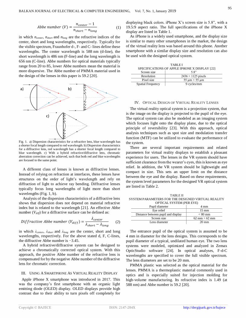
Fig. 1. a) Dispersion characteristics for a refractive lens, blue wavelength has a shorter focal length compared to red wavelength. b) Dispersion characteristics for a diffractive lens, red wavelength has a shorter focal length compared to blue wavelength. c) With a hybrid refractive/diffractive lens, chromatic aberration correction can be achieved, such that both red and blue wavelengths are focused to the same point.

A different class of lenses is known as diffractive lenses.

Instead of relying on refraction at interfaces, these lenses have

structures on the order of light’s wavelength and rely on

diffraction of light to achieve ray bending. Diffractive lenses

typically focus long wavelengths of light more than short

wavelengths (Fig. 1, b).

Analysis of the dispersion characteristics of a diffractive lens

shows that dispersion does not depend on material refractive

index but is related to the wavelength [21]. An effective Abbe

number (Vdiff) for a diffractive surface can be defined as:

𝐷𝑖𝑓𝑓𝑟𝑎𝑐𝑡𝑖𝑣𝑒 𝐴𝑏𝑏𝑒 𝑛𝑢𝑚𝑏𝑒𝑟 (𝑉𝑑𝑖𝑓𝑓) =𝜆𝑐𝑒𝑛𝑡𝑒𝑟

𝜆𝑠ℎ𝑜𝑟𝑡 − 𝜆𝑙𝑜𝑛𝑔 (2)

in which λcenter, λshort and λlong are the center, short and long

wavelengths, respectively. For the above stated d, F, C-lines,

the diffractive Abbe number is −3.45.

A hybrid refractive/diffractive system can be designed to

achieve a chromatically corrected optical system. With this

approach, the positive Abbe number of the refractive lens is

compensated for by the negative Abbe number of the diffractive

lens for chromatic correction.

III. USING A SMARTPHONE AS VIRTUAL REALITY DISPLAY

Apple iPhone X smartphone was introduced in 2017. This

was the company’s first smartphone with an organic light

emitting diode (OLED) display. OLED displays provide high

contrast due to their ability to turn pixels off completely for

displaying black colors. iPhone X’s screen size is 5.8”, with a

19.5:9 aspect ratio. The full specifications of the iPhone X

display are listed in Table 1.

As iPhone is a widely used smartphone, and the display size

is similar to many other smartphones in the market, the design

of the virtual reality lens was based around this phone. Another

smartphone with a similar display size and resolution can also

be used with the designed optical system.

TABLE I

SPECIFICATIONS OF APPLE IPHONE X DISPLAY [22] Screen size 5.8”

Resolution 2436 × 1125 pixels

Pixel size 55 µm × 55 µm

Spatial Frequency 9 cycles/mm

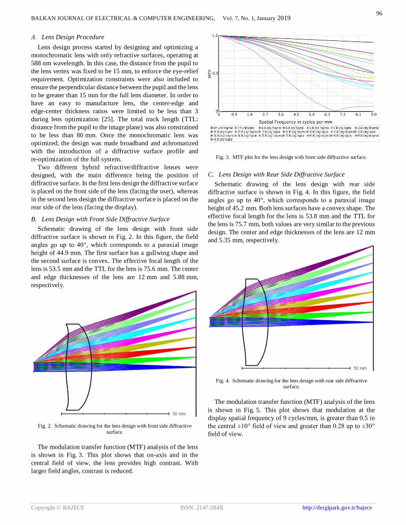
IV. OPTICAL DESIGN OF VIRTUAL REALITY LENSES

The virtual reality optical system is a projection system, that

is the image on the display is projected to the pupil of the eye.

The optical system can also be modeled as an imaging system

which focuses light onto the display plane, due to the optical

principle of reversibility [23]. With this approach, optical

analysis techniques such as spot size and modulation transfer

function (MTF) can be utilized to evaluate the performance of

the system.

There are several important requirements and related

parameters for virtual reality displays to establish a pleasant

experience for users. The lenses in the VR system should have

sufficient clearance from the wearer’s eyes, this is known as eye

relief. In addition, the VR system should be lightweight and

compact in size. This sets an upper limit on the distance

between the eye and the display. Based on these requirements,

the system level parameters for the designed VR optical system

are listed in Table 2.

TABLE II

SYSTEM PARAMETERS FOR THE DESIGNED VIRTUAL REALITY OPTICAL SYSTEM (PER EYE)

Pupil diameter 4 mm

Eye relief 15 mm

Distance between pupil and display < 80 mm

Screen size 62 mm × 62 mm

Lens diameter 20 mm

The entrance pupil of the optical system is assumed to be

4 mm in diameter for the lens designs. This corresponds to the

pupil diameter of a typical, undilated human eye. The two lens

systems were modeled, optimized and analyzed in Zemax

OpticStudio software [24]. In optical analyses, F-d-C

wavelengths are specified to cover the full visible spectrum.

The lens diameters are set to be 20 mm.

PMMA plastic was selected as the optical material for the

lenses. PMMA is a thermoplastic material commonly used in

optics and is especially suited for injection molding for

high-volume manufacturing. Its refractive index is 1.49 (at

588 nm) and Abbe number is 59.2 [20].

95

BALKAN JOURNAL OF ELECTRICAL & COMPUTER ENGINEERING, Vol. 7, No. 1, January 2019

Copyright © BAJECE ISSN: 2147-284X http://dergipark.gov.tr/bajece

A. Lens Design Procedure

Lens design process started by designing and optimizing a

monochromatic lens with only refractive surfaces, operating at

588 nm wavelength. In this case, the distance from the pupil to

the lens vertex was fixed to be 15 mm, to enforce the eye-relief

requirement. Optimization constraints were also included to

ensure the perpendicular distance between the pupil and the lens

to be greater than 15 mm for the full lens diameter. In order to

have an easy to manufacture lens, the center-edge and

edge-center thickness ratios were limited to be less than 3

during lens optimization [25]. The total track length (TTL:

distance from the pupil to the image plane) was also constrained

to be less than 80 mm. Once the monochromatic lens was

optimized, the design was made broadband and achromatized

with the introduction of a diffractive surface profile and

re-optimization of the full system.

Two different hybrid refractive/diffractive lenses were

designed, with the main difference being the position of

diffractive surface. In the first lens design the diffractive surface

is placed on the front side of the lens (facing the user), whereas

in the second lens design the diffractive surface is placed on the

rear side of the lens (facing the display).

B. Lens Design with Front Side Diffractive Surface

Schematic drawing of the lens design with front side

diffractive surface is shown in Fig. 2. In this figure, the field

angles go up to 40°, which corresponds to a paraxial image

height of 44.9 mm. The first surface has a gullwing shape and

the second surface is convex. The effective focal length of the

lens is 53.5 mm and the TTL for the lens is 75.6 mm. The center

and edge thicknesses of the lens are 12 mm and 5.88 mm,

respectively.

Fig. 2. Schematic drawing for the lens design with front side diffractive surface.

The modulation transfer function (MTF) analysis of the lens

is shown in Fig. 3. This plot shows that on-axis and in the

central field of view, the lens provides high contrast. With

larger field angles, contrast is reduced.

Fig. 3. MTF plot for the lens design with front side diffractive surface.

C. Lens Design with Rear Side Diffractive Surface

Schematic drawing of the lens design with rear side

diffractive surface is shown in Fig. 4. In this figure, the field

angles go up to 40°, which corresponds to a paraxial image

height of 45.2 mm. Both lens surfaces have a convex shape. The

effective focal length for the lens is 53.8 mm and the TTL for

the lens is 75.7 mm, both values are very similar to the previous

design. The center and edge thicknesses of the lens are 12 mm

and 5.35 mm, respectively.

Fig. 4. Schematic drawing for the lens design with rear side diffractive surface.

The modulation transfer function (MTF) analysis of the lens

is shown in Fig. 5. This plot shows that modulation at the

display spatial frequency of 9 cycles/mm, is greater than 0.5 in

the central ±10° field of view and greater than 0.28 up to ±30°

field of view.

96

BALKAN JOURNAL OF ELECTRICAL & COMPUTER ENGINEERING, Vol. 7, No. 1, January 2019

Copyright © BAJECE ISSN: 2147-284X http://dergipark.gov.tr/bajece

Fig. 4. MTF plot for the lens design with rear side diffractive surface.

When analyzed in imaging configuration, both lenses have

negative (barrel) distortion. This means that in the projection

configuration, they have the opposite, positive (pincushion)

distortion. Due to this pincushion distortion effect of VR lenses,

it is common practice to pre-distort display video feed of virtual

reality systems through digital image processing [26]. If an

image that is pre-distorted with the unique distortion profile of

the lens is displayed on the screen, and a VR system with the

corresponding lens is used to view this image, the viewer would

see a distortion-free (i.e. rectilinear) image. Designing an

optical system to have some optimal degree of distortion can

also allow for correcting other optical aberrations more

effectively [27-29].

V. DISCUSSIONS

The two hybrid refractive/diffractive lenses presented above

have similar optical performance, as can be seen by comparing

the MTF plots shown in Fig. 3 and Fig. 5. Both designs provide

high contrast in the central field of view, and performance

degradation is apparent at large field angles. Either lens design

can be manufactured to implement high-resolution VR displays

systems.

As shown in Fig. 2, the lens design with front side diffractive

surface has a “gull-wing” profile for the front surface. This

gullwing type of surface profile is difficult to manufacture and

test [30]. Therefore, from a robust, high-volume manufacturing

perspective, the lens design with rear side diffractive surface (as

shown in Fig. 4) would be preferred over the other lens design.

VI. CONCLUSION

Optical design and performance analysis of a high-contrast

wearable display system is presented. A compact and simple

design with a single plastic lens element is achieved through a

hybrid refractive/diffractive lens design approach.

REFERENCES

[1] L. P. Berg and J. M. Vance, "Industry use of virtual reality in product design and manufacturing: a survey," Virtual Reality, vol. 21, pp. 1-17, 2017.

[2] Seth, J. M. Vance and J. H. Oliver, "Virtual reality for assembly methods prototyping: a review," Virtual reality, vol. 15, pp. 5-20, 2011.

[3] L. Freina and M. Ott, "A Literature Review on Immersive Virtual Reality in Education: State Of The Art and Perspectives.," eLearning & Software for Education, 2015.

[4] N. E. Seymour, A. G. Gallagher, S. A. Roman, M. K. O’brien, V. K. Bansal, D. K. Andersen and R. M. Satava, "Virtual reality training improves operating room performance: results of a randomized, double-blinded study," Annals of surgery, vol. 236, p. 458, 2002.

[5] F. E. Sahin, "Open-source optimization algorithms for optical design," Optik, vol. 178, pp. 1016-1022, 2019.

[6] L. Livshits and D. C. Dilworth, "Trends in optical design from 1988 to 2018… where to from here?," Advanced Optical Technologies, vol. 7, pp. 335-341, 2018.

[7] F. E. Sahin, "Lens design for active alignment of mobile phone cameras," Optical Engineering, vol. 56, p. 065102, 2017.

[8] R. Konrad, N. Padmanaban, K. Molner, E. A. Cooper and G. Wetzstein, "Accommodation-invariant Computational Near-eye Displays," ACM Trans. Graph. (SIGGRAPH), no. 36, 2017.

[9] F. E. Sahin and R. Laroia, "Light L16 Computational Camera," in Applied Industrial Optics: Spectroscopy, Imaging and Metrology, 2017.

[10] Lanman and D. Luebke, "Near-eye light field displays," ACM Transactions on Graphics (TOG), vol. 32, p. 220, 2013.

[11] J. P. Rolland, R. L. Holloway and H. Fuchs, "Comparison of optical and video see-through, head-mounted displays," in Telemanipulator and Telepresence Technologies, 1995.

[12] F. E. Sahin, B. P. McIntosh, P. J. Nasiatka, J. D. Weiland, M. S. Humayun and A. R. Tanguay, "Eye-tracked extraocular camera for retinal prostheses," in Frontiers in Optics, 2015.

[13] Cutolo, P. D. Parchi and V. Ferrari, "Video see through AR head-mounted display for medical procedures," in Mixed and Augmented Reality (ISMAR), 2014 IEEE International Symposium on, 2014.

[14] Google Cardboard, https://vr.google.com/cardboard/ (Last accessed: Dec 6, 2018).

[15] Oculus VR, https://www.oculus.com/ (Last accessed: Dec 6, 2018). [16] HTC Vive, https://www.vive.com/ (Last accessed: Dec 6, 2018). [17] S.-W. Yang, K.-L. Huang, C.-Y. Chen and R.-S. Chang, "Wide-angle

lens design," in Computational Optical Sensing and Imaging, 2014. [18] F. E. Sahin, "Fisheye lens design for sun tracking cameras and

photovoltaic energy systems," Journal of Photonics for Energy, vol. 8, p. 035501, 2018.

[19] J. Kumler and M. L. Bauer, "Fish-eye lens designs and their relative performance," in Current Developments in Lens Design and Optical Systems Engineering, 2000.

[20] N. Sultanova, S. Kasarova and I. Nikolov, "Dispersion properties of optical polymers," Acta Physica Polonica-Series A General Physics, vol. 116, p. 585, 2009.

[21] M. Schaub, J. Schwiegerling, E. Fest, R. H. Shepard and A. Symmons, "Molded Optics: Design and Manufacture," CRC Press, 2016, pp. 28-32.

[22] Apple iPhone X, https://www.apple.com/iphone-x/ (Last accessed: Sep. 12, 2018)

[23] Hecht, "Optics," Pearson Education, 2001, p. 107. [24] Zemax OpticStudio, Zemax LLC, Washington, USA.

https://www.zemax.com/ [25] S. Thibault, J. Parent, H. Zhang, X. Du and P. Roulet, "Consumer

electronic optics: how small can a lens be: the case of panomorph lenses," in Current Developments in Lens Design and Optical Engineering XV, 2014.

[26] S. Lee and H. Hua, "A robust camera-based method for optical distortion calibration of head-mounted displays," Journal of Display Technology, vol. 11, pp. 845-853, 2015.

[27] F. E. Sahin, P. J. Nasiatka, J. D. Weiland, M. S. Humayun and A. R. Tanguay, "Optimal Design of Miniature Wide-Angle Computational Cameras for Retinal Prostheses and Wearable Visual Aids," in Frontiers in Optics, 2014.

[28] F. E. Sahin, P. J. Nasiatka and A. R. Tanguay, "Lateral Chromatic Aberration Optimization in Wide-Field-of-View Computational Cameras," in Frontiers in Optics, 2015.

[29] F. E. Sahin and A. R. Tanguay, "Distortion optimization for wide-angle computational cameras," Optics Express, vol. 26, pp. 5478-5487, 2018.

[30] Symmons, J. Huddleston and D. Knowles, "Design for manufacturability and optical performance trade-offs using precision glass molded aspheric lenses," in Polymer Optics and Molded Glass Optics: Design, Fabrication, and Materials 2016, 2016.

97

BALKAN JOURNAL OF ELECTRICAL & COMPUTER ENGINEERING, Vol. 7, No. 1, January 2019

Copyright © BAJECE ISSN: 2147-284X http://dergipark.gov.tr/bajece

BIOGRAPHIES

FURKAN EMRE SAHIN received his B.S.

degree from Bogazici University, Istanbul,

Turkey, and his Ph.D. from the University

of Southern California, Los Angeles, USA,

in Electrical Engineering. His work in the

industry includes optical system design of

miniature cameras and optical sensors. His

research interests include development of

innovative imaging and sensing systems

for consumer, industrial and biomedical applications, optical

system design, and computational photography.

98


Recommended