TRANSPORTATION RESEARCH RECORD 1291 Design of Large-Stone Asphalt Mixes for Low-Volume Roads Using 6-in.-Diameter Marshall Specimens PRITHVI S. KANDHAL Premature rutting of road pavements constructed for hauling coal and Jogs is common. Although these roads carry low volumes of traffic, they are subjected to heavy and channelized wheel loads. Unfortunately. conventional asphalt mixes containing aggregates Jess than 1-in. maximum size in the base or binder course tend to develop premature rutting under these conditions. Many asphalt technologists believe that the use of large-size stone (maximum size of more than 1 in.) will minimize or eliminate this problem. Large-stone mixes are also economical for low-volume roads because of substantially reduced asphalt contents. However, most agencies use the Marshall design procedure (ASTM D1559), which uses a 4-in.-diameter compaction mold intended for mixes con- taining aggregate up to 1-in. maximum size only. This has inhib- ited the use of large-stone mixes. A standard method for pre- paring and testing 6-in.-diameter specimens has been presented. Mixes containing aggregate up to 2-in. maximum nominal size can be tested. A typical mix design using 6-in. specimens for a coal-haul road in Kentucky is given. Construction data and expe- rience gained from field projects in Kentucky are also included. The proposed test method may be useful in determining the opti- mum asphalt content of large-stone asphalt mixes that are rec- ommended for use on low-volume roads subjected to heavy and channelized wheel loads. Premature rutting of road pavements constructed for hauling coal and logs is quite common. The problem of these roads that provide the essential first link in the transportation chain that brings the products of mines and forest to market is unique. Although these roads carry low volumes of traffic, they are subjected to heavy and channelized wheel loads. Coal-haul roads in Kentucky have been reported to carry trucks with gross loads ranging from 90,000 to 150,000 lb. Tire pressures are also higher than generally encountered, ranging from 100 to 130 pounds per square inch (psi). Unfortunately, conventional hot-mix asphalt (HMA) mixes containing aggregates less than 1-in. maximum size tend to develop premature rutting under these conditions. Many asphalt technologists believe that the use of large-size stone (maxi- mum size of more than 1 in.) will minimize or eliminate this problem. Large-stone mixes are also economical for low- volume roads because of substantially reduced asphalt con- tents. A thin asphalt surfacing needs to be provided over the large-stone asphalt mix to obtain smooth surface. Marshall mix design procedures are used by 76 percent of the states in the United States according to a survey conducted in 1984 (J). The equipment specified in the Marshall proce- National Center for Asphalt Technology, 211 Ramsey Hall, Auburn University, Ala. 36849-5354. dure (ASTM 01559) consists of a 4-in.-diameter compaction mold that is intended for mixtures containing aggregate up to 1-in. maximum size only. This has also inhibited the use of HMA containing aggregate larger than I in. because it cannot be tested by the standard Marshall mix design procedures. There are other test procedures such as gyratory compaction. TRRL (Transport and Road Research Laboratory. U.K.) refusal test, and Minnesota DOT vibrating hammer. which use 6-in.-diameter molds accommodating 1 1 /2- to 2-in. maxi- mum aggregate size (2). However, most agencies are reluctant to buy new equipment because of cost and complexity. They tend to prefer and use the existing equipment and method- ology (such as Marshall test) with some modifications. The term "large-stone" is a relative one. For the purpose of this report, large-stone mix is defined as an aggregate with a maximum size of more than 1 in., which cannot be used in preparing standard 4-in.-diameter Marshall specimens. BACKGROUND OF DEVELOPMENT Pennsylvania Department of Transportation (PennDOT) implemented Marshall mix design procedures in the early 1960s. The Marshall method was generally based on ASTM D1559 (Standard Test Method for Resistance to Plastic Flow of Bituminous Mixtures Using Marshall Apparatus). ASTM Dl559 specifies the use of 4-in.-diameter specimen mold for mixes containing aggregate up to 1-in. maximum size. The compaction hammer weighs 10 lb and a free fall of 18 in. is used. It became apparent that ASTM Dl559 could not be used for designing Pennsylvania ID-2 binder course mix and base course mix, which specified maximum permissible sizes of 1 Y2 and 2 in., respectively. Therefore. PennDOTcompleted a study in 1969 to develop the equipment and procedure for testing 6-in.-diameter specimens (3). A series of compaction tests was run using 4- and 6-in.- diameter specimens of wearing and binder mixes. The nom- inal height of the 6-in.-diameter specimen was increased to 3% in. to provide the same ratio of diameter to height that is used for a 4-in.-diameter x 2Y2-in.-high specimen. When the 6-in. compactor was designed, it was assumed that the weight of the hammer should be increased in proportion to the face area of the Marshall specimen, and the height of hammer drop and the number of blows on the face of the specimen should remain the same as that used for the 4-in.-diameter specimens. The weight of the hammer, therefore, was increased from 10 to 22.5 lb, and the hammer drop was maintained at
Transcript
TRANSPORTATION RESEARCH RECORD 1291
Design of Large-Stone Asphalt Mixes for Low-Volume Roads Using 6-in.-Diameter Marshall Specimens
PRITHVI S. KANDHAL
Premature rutting of road pavements constructed for hauling coal and Jogs is common. Although these roads carry low volumes of traffic, they are subjected to heavy and channelized wheel loads. Unfortunately. conventional asphalt mixes containing aggregates Jess than 1-in. maximum size in the base or binder course tend to develop premature rutting under these conditions. Many asphalt technologists believe that the use of large-size stone (maximum size of more than 1 in.) will minimize or eliminate this problem. Large-stone mixes are also economical for low-volume roads because of substantially reduced asphalt contents. However, most agencies use the Marshall design procedure (ASTM D1559), which uses a 4-in.-diameter compaction mold intended for mixes containing aggregate up to 1-in. maximum size only. This has inhibited the use of large-stone mixes. A standard method for preparing and testing 6-in.-diameter specimens has been presented. Mixes containing aggregate up to 2-in. maximum nominal size can be tested. A typical mix design using 6-in. specimens for a coal-haul road in Kentucky is given. Construction data and experience gained from field projects in Kentucky are also included. The proposed test method may be useful in determining the optimum asphalt content of large-stone asphalt mixes that are recommended for use on low-volume roads subjected to heavy and channelized wheel loads.
Premature rutting of road pavements constructed for hauling coal and logs is quite common. The problem of these roads that provide the essential first link in the transportation chain that brings the products of mines and forest to market is unique. Although these roads carry low volumes of traffic, they are subjected to heavy and channelized wheel loads. Coal-haul roads in Kentucky have been reported to carry trucks with gross loads ranging from 90,000 to 150,000 lb. Tire pressures are also higher than generally encountered, ranging from 100 to 130 pounds per square inch (psi).
Unfortunately, conventional hot-mix asphalt (HMA) mixes containing aggregates less than 1-in. maximum size tend to develop premature rutting under these conditions. Many asphalt technologists believe that the use of large-size stone (maximum size of more than 1 in.) will minimize or eliminate this problem. Large-stone mixes are also economical for lowvolume roads because of substantially reduced asphalt contents. A thin asphalt surfacing needs to be provided over the large-stone asphalt mix to obtain smooth surface.
Marshall mix design procedures are used by 76 percent of the states in the United States according to a survey conducted in 1984 (J). The equipment specified in the Marshall proce-
National Center for Asphalt Technology, 211 Ramsey Hall, Auburn University, Ala. 36849-5354.
dure (ASTM 01559) consists of a 4-in.-diameter compaction mold that is intended for mixtures containing aggregate up to 1-in. maximum size only. This has also inhibited the use of HMA containing aggregate larger than I in. because it cannot be tested by the standard Marshall mix design procedures. There are other test procedures such as gyratory compaction. TRRL (Transport and Road Research Laboratory. U.K.) refusal test, and Minnesota DOT vibrating hammer. which use 6-in.-diameter molds accommodating 11/2- to 2-in. maximum aggregate size (2). However, most agencies are reluctant to buy new equipment because of cost and complexity. They tend to prefer and use the existing equipment and methodology (such as Marshall test) with some modifications.
The term "large-stone" is a relative one. For the purpose of this report, large-stone mix is defined as an aggregate with a maximum size of more than 1 in., which cannot be used in preparing standard 4-in.-diameter Marshall specimens.
BACKGROUND OF DEVELOPMENT
Pennsylvania Department of Transportation (PennDOT) implemented Marshall mix design procedures in the early 1960s. The Marshall method was generally based on ASTM D1559 (Standard Test Method for Resistance to Plastic Flow of Bituminous Mixtures Using Marshall Apparatus). ASTM Dl559 specifies the use of 4-in.-diameter specimen mold for mixes containing aggregate up to 1-in. maximum size. The compaction hammer weighs 10 lb and a free fall of 18 in. is used. It became apparent that ASTM Dl559 could not be used for designing Pennsylvania ID-2 binder course mix and base course mix, which specified maximum permissible sizes of 1 Y2 and 2 in., respectively. Therefore. PennDOTcompleted a study in 1969 to develop the equipment and procedure for testing 6-in.-diameter specimens (3).
A series of compaction tests was run using 4- and 6-in.diameter specimens of wearing and binder mixes. The nominal height of the 6-in.-diameter specimen was increased to 3% in. to provide the same ratio of diameter to height that is used for a 4-in.-diameter x 2Y2-in.-high specimen. When the 6-in. compactor was designed, it was assumed that the weight of the hammer should be increased in proportion to the face area of the Marshall specimen, and the height of hammer drop and the number of blows on the face of the specimen should remain the same as that used for the 4-in.-diameter specimens. The weight of the hammer, therefore, was increased from 10 to 22.5 lb, and the hammer drop was maintained at
254
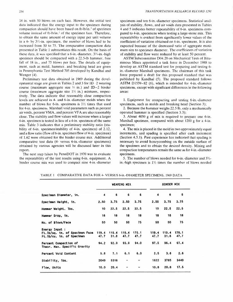
18 in . with 50 blows on each face . However. the initial test data indicated that the energy input to the specimen during compaelion should have been based on ft-lb/in. 3 of specimen volume instead of ft-lb/in .2 of the specimen face. Therefore. to obtain the same amount of energy input per unit volume in a 6- by 3Y.i-in. specimen, the number of blows had to be increased from 50 to 75. The comparative compaction data presented in Table 1 substantiates this result. On the basis of these data. it was specified that a 6-in .-diameter. 33/~-in.-high specimen should be compacted with a 22.5-lb hammer. free fall of 18 in . . and 75 blows per face. The details of equipment. such as mold . hammer. and breaking head are given in Pennsylvania Test Method 705 developed by Kandhal and Wenger (4) .
Preliminary test data obtained in 1969 during the developmental stage are given in Tables 2 and 3 for ID-2 wearing course (maximum aggregate size 1/2 in.) and ID-2 binder course (maximum aggregate size 11/2 in.) mixtures, respectively . The data indicate that reasonably close compaction levels are achieved in 4- and 6-in .-diameter molds when the number of blows for 6-in. specimens is 11/2 times that used for 4-in . specimens. Marshall void parameters such as percent air voids , percent VMA, and percent VF A are also reasonably close . The stability and flow values will increase when a larger 6-in . specimen is tested in lieu of a 4-in . specimen of the same mix. Table 3 indicates that a preliminary stability ratio (stability of 6-in. specimen/stability of 4-in. specimen) of 2.12, and a flow ratio (flow of 6-in. specimen/flow of 4-in. specimen) of 1.62 were obtained for the binder course mix. Additional comparative test data (4- versus 6-in .-diameter specimens) obtained by various agencies will be discussed later in this report.
The next step taken by PennDOT in 1970 was to evaluate the repeatability of the test results using 6-in. equipment. A binder course mix was used to compact nine 4-in.-diameter
TRANSPORTATION RESEARCH RECORD 1291
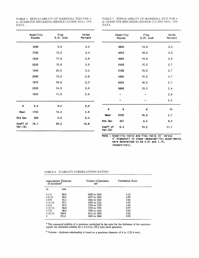
specimens and ten 6-in .-diameter specimens. Statistical analysis of stability. flows. and air voids data presented in Tables 4 and 5 indicates better repeatability of 6-in. specimens compared to 4-in. specimens when testing a large-stone mix. This repeatability is evident from significantly lower values of the coefficient of variation obtained on 6-in. specimens. It is also expected because of the decreased ratio of aggregate maximum size to specimen diameter. The coefficients of variation of stability and flow were reduced by at least 50 percent.
ASTM Subcommittee 004 .20 on Mechanical Tests of Bituminous Mixes appointed a task force in December 1988 to develop an ASTM standard test for preparing and testing 6-in .-diameter Marshall specimens. The chairman of this task force prepared a draft for this proposed standard that was published by Kandhal (5) . The proposed standard follows ASTM 01559-82 (6), which is intended for 4-in.-diameter specimens, except with significant differences in the following areas:
1. Equipment for compacting and testing 6-in.-Jiamt:ler specimens, such as molds and breaking head (Section 3) ;
2. Because the hammer weighs 22.5 lb, only a mechanically operated hammer is specified (Section 3.3) ;
3. About 4050 g of mix is required to prepare one 6-in . Marshall specimen, compared with about 1200 g for a 4-in . specimen;
4. The mix is placed in the mold in two approximately equal increments, and spading is specified after each increment (Section 4.5.1 ). Past experience has indicated that spading is necessary to avoid honeycombing on the outside surface of the specimen and to obtain the desired density. Mixing and compaction temperatures remain the same as for 4-in.-diameter specimens.
5. The number of blows needed for 6-in.-diameter and 33/ •
in.-high specimen is 11/2 times the number of blows needed
TABLE I COMPARATIVE DATA FOR 4- VERSUS 6-in.-DIAMETER SPECIMENS. 1969 DATA
Energy Input : Ft. lb/sq. in. of Specimen Face 119.4 119.4 119.4 170.1 119.4 119.4 179.1 Ft. lb/cu. in. of Specimen 47. 7 31.8 47.7 47.7 47.7 31.8 47.7
Percent Compaction of 94.2 92.9 93.9 94.0 97.5 96.4 97.4 Theor. Max. Specific Gravity
Percent Void Content 5.8 7. 1 6.1 6.0 2.5 3.6 2.6
Stabi 11ty, lbs . 2049 5316 1622 3785 3440
Flow, Units 10.0 20 . 4 10 . 8 20.8 17.5
Kandhal
TABLE 2 COMPARATIVE TEST DATA FOR 4- VERSUS 6-in.-DIAMETER SPECIMENS (WEARING COURSE)
Source : Pennsylvania Dept. of Transportation Mix type : ID - 2 Wearing Course. (1969 Data)
Aggregates : Limestone coarse aggregate and limestone fine aggregate. -Des1gn Gradation (X Passing) :
Remarks Data on Stability and Flow of 6" specimens is not available.
Remarks: Results are based on average of six 4"-dia. specimens and three 6"-dia. specimens.
255
for 4-in.-diameter and 2'/~-in.-high specimen to obtain equivalent compaction level (Note 4 ).
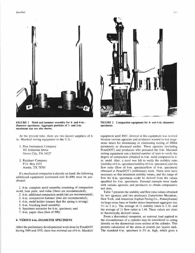
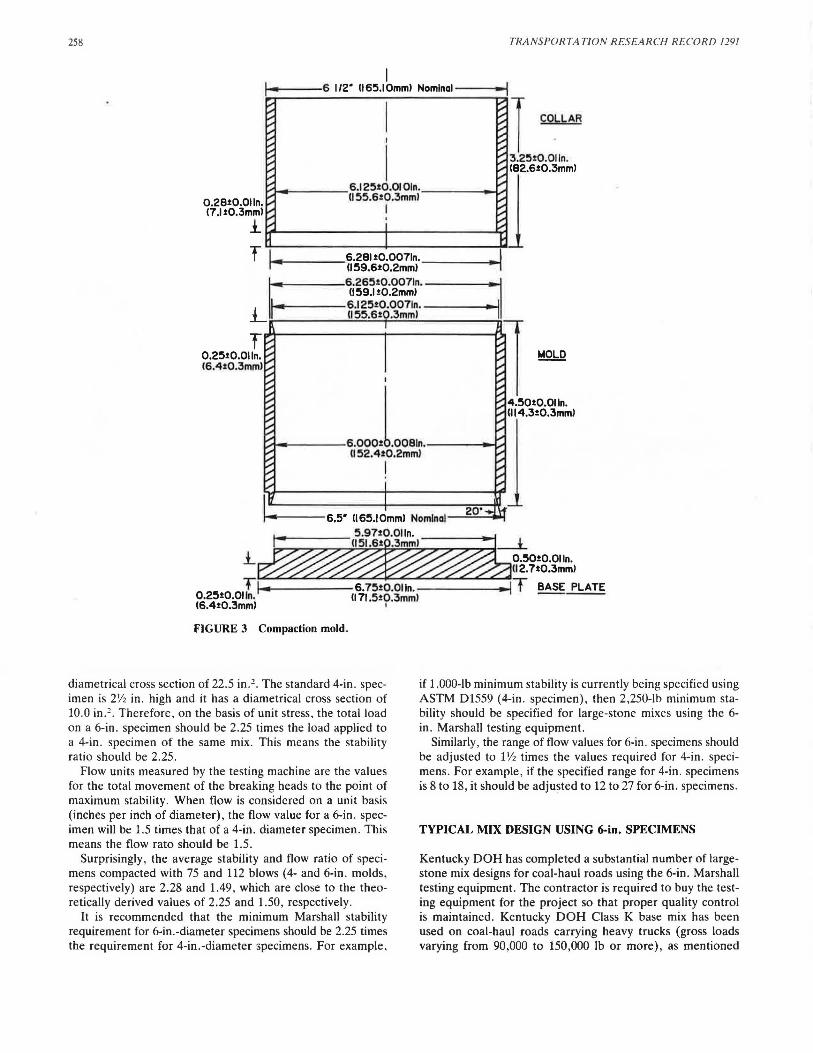
of specimens (Figure 2). Figures 3 through 6 show the details of the test equipment.
6. Stability correlations ratios have been revised and are presented in Table 6. These ratios are based on percentage of increase or decrease in specimen volumes, similar to ASTM 01559.
Relative sizes of mold and hammer assembly for compacting 4- and 6-in. specimens are shown in Figure 1. The same mechanical compactor can be used for compacting both types
Because the hammer weighs 22.5 lb and the number of blows on each side is 75 or 112 depending on the anticipated traffic, some crushing of the aggregate at the surface has been observed. However, its effect on Marshall properties is believed to be minimal.
Vigorous spading in the mold is necessary to prevent voids near the large stones. The mix should not be allowed to cool below the intended compaction temperature.
TABLE 3 COMPARATIVE TEST DATA FOR 4- VERSUS 6-in.-DIAMETER SPECIMENS (BINDER COURSE)
Source : Pennsylvania Dept. of Transportation (1969 Data)
Remarks Results are based on average of 3 specimens each.
150 1100
10 7
4" Specimen
1622
10.8
2.12
1.62
Stability Ratio= Stability of 6" specimen I Stability of 4" specimen. Flow Ratio = Flow of 6" specimen I Flow of 4" specimen.
1200
3
6" Specimen
3440
17.5
TABLE 4 REPEAT ABILITY OF MARSHALL TEST FOR 4- TABLE 5 REPEATABILITY OF MARSHALL TEST FOR 6-in.-DIAMETER SPECIMENS (BINDER COURSE MIX). 1970 in .-DIAMETER SPECIMENS (BINDER COURSE MIX). 1970 DATA.
Stab1l ity Pounds
1290
1750
1635
2035
1540
2090
1975
2200
1620
N 9.0
Mean 1793
Std Dev 300
Coef f of 16.7 Var. (i)
DATA
Flow Voids Stability Flow Voids 0.01 Inch Percent Pounds 0.01 Inch Percent
1608 to 1626 1637 to 1665 1666 to 1694 1695 to 1723 1724 to 1752 1753 to 1781 1782 to 1810 1811 to 1839 1840 to 1868
4" diameter) in these repeatability experiments were determined to be 2.81 and 1.15, respectively.
Correlation Ratio
1.12 1.09 1.06 1.03 1.00 0.97 0.95 0.92 0.90
• The measured stability of a specimen mul1iplied by the raiio for the thickness of !he specimen equals !he corrected stability for a 3-3/4-in. (95.2 mm) thick specimen.
8 Volume - lhickness relationship is based on a specimen diameter of 6 in. (152.4 mm).
Kandhal
FIGURE I Mold and hammer assembly for 4- and 6-in.diameter specimens. Aggregate particles of I- and 2-in. maximum size are also shown.
At the present time. there are two known suppliers of 6-in. Marshall testing equipment in the U.S.:
1. Pine Instrument Company 101 Industrial Drive Grove City, PA 16127
2. Rainhart Company P.O. Box 4533 Austin, TX 78765
If a mechanical compactor is already on hand, the following additional equipment (estimated cost $1,800) must be purchased:
1. 6-in . complete mold assembly consisting of compaction mold, base plate, and collar (three are recommended);
2. 6-in. additional compaction molds (six are recommended); 3. 6-in. compaction hammer (two are recommended); 4. 6-in . mold holder (ensure that the spring is strong) ; 5. 6-in. breaking head assembly; 6. Specimen extractor for 6-in. specimen; and 7. 6-in. paper discs (box of 500).
4- VERSUS 6-in.-DIAMETER SPECIMENS
After the preliminary developmental work done by PennDOT during 1969 and 1970, there was minimal use of 6-in. Marshall
,_ni.
FIGURE 2 Compaction equipment for 4- and 6-in.-diameter specimens.
equipment until 1987. Interest in this equipment was revived because various agencies and producers wanted to test largestone mixes for minimizing or eliminating rutting of HMA pavements as discussed earlier. These agencies (including PennDOT) and producers who procured the 6-in . Marshall testing equipment ran a limited number of tests to verify the degree of compaction obtained in 6-in. mold compared to 4-in. mold. Also, a need was felt to verify the stability ratio (stability of 6-in . specimen/stability of 4-in. specimen) and the flow ratio (flow of 6-in . specimen/flow of 4-in . specimen) obtained in PennDOTs preliminary work. These tests were necessary so that minimum stability values, and the range of flow for 6-in. specimens could be derived from the values specified for 4-in. specimens. Personal contacts were made with various agencies and producers to obtain comparative test data.
Table 7 presents the stability and flow ratio values obtained by two agencies and two producers (Jamestown Macadam. New York, and American Asphalt Paving Co., Pennsylvania) on large-stone base or binder mixes (maximum aggregate size lY2 to 2 in.) . The average of 11 stability ratios is 2.18, and the average of 11 flow ratios is 1.44. These values are close to theoretically derived values.
From a theoretical viewpoint, an external load applied to the circumference of a cylinder may be considered as acting directly on the diametrical cross section of the cylinder. This permits calculation of the stress in pounds per square inch. The standard 6-in . specimen is 3% in . high, which gives a
258 TRANSPORTA TION RESEA RCH RECORD 1291
I i-- --6 112· 116!5.IOmml Nomlnal - --..i
I COLLAR
I
I l"",to ___ ___ 6.125t0.0101n. _ ____ .......,
II !55.6t0.3mml o.2eio.011n. I 17.Jt0.3mml 1...._ ____________ _
TI.--•- -
I
r...+----6.000.LO .... ----oo{A II 52.4t0.2mml
I
FIGURE 3 Compaction mold.
diametrical cross section of 22.5 in .2 . The standard 4-in. specimen is 2\/2 in. high and it has a diametrical cross section of 10.0 in. 2 • Therefore, on the basis of unit stress, the total load on a 6-in. specimen should be 2.25 times the load applied to a 4-in . specimen of the same mix. This means the stability ratio should be 2.25 .
Flow units measured by the testing machine are the values for the total movement of the breaking heads to the point of maximum stability. When flow is considered on a unit basis (inches per inch of diameter), the flow value for a 6-in. specimen will be 1.5 times that of a 4-in. diameter specimen. This means the flow rato should be 1.5.
Surprisingly , the average stability and flow ratio of specimens compacted with 75 and 112 blows (4- and 6-in. molds , respectively) are 2.28 and 1.49, which are close to the theoretically derived values of 2.25 and 1.50, respectively.
It is recommended that the minimum Marshall stability requirement for 6-in.-diameter specimens should be 2.25 times the requirement for 4-in.-diameter specimens. For example,
if 1,000-lb minimum stability is currently being specified using ASTM D1559 (4-in . specimen) , then 2,250-lb minimum stability should be specified for large-stone mixes using the 6-in. Marshall testing equipment.
Similarly, the range of flow values for 6-in . specimens should be adjusted to l 1/ 2 times the values required for 4-in . specimens . For example, if the specified range for 4-in. specimens is 8 to 18, it should be adjusted to 12 to 27 for 6-in. specimens.
TYPICAL MIX DESIGN USING 6-in. SPECIMENS
Kentucky DOH has completed a substantial number of largestone mix designs for coal-haul roads using the 6-in . Marshall testing equipment . The contractor is required to buy the testing equipment for the project so that proper quality control is maintained. Kentucky DOH Class K base mix has been used on coal-haul roads carrying heavy trucks (gross loads varying from 90,000 to 150,000 lb or more), as mentioned
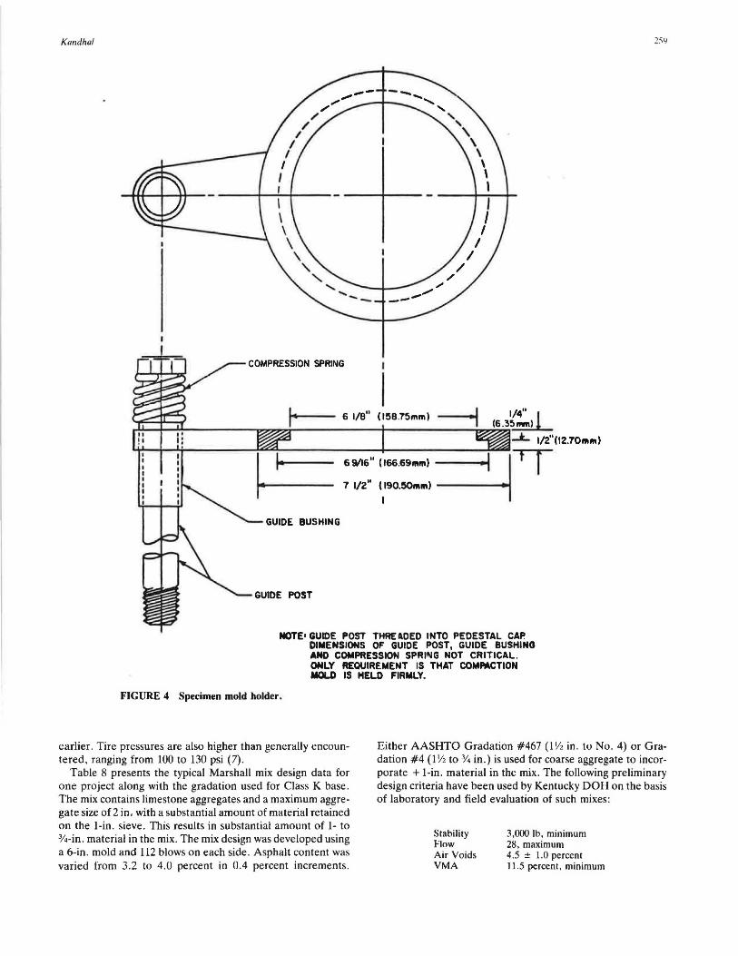
DIMENSIONS OF GUIDE POST, GUIDE BUSHING AND COMPRESSION SPRll\IG NOT CRITICAL. ONLY REQUIREMENT IS THAT COMMCTION MOLD IS HELD FIRMLY.
259
earlier. Tire pressures are also higher than generally encountered, ranging from 100 to 130 psi (7).
Table 8 presents the typical Marshall mix design data for one project along with the gradation used for Class K base . The mix contains limestone aggregates and a maximum aggregate size of 2 in. with a substantial amount of material retained on the 1-in. sieve. This results in substantial amount of 1- to %-in. material in the mix. The mix design was developed using a 6-in. mold and 112 blows on each side. Asphalt content was varied from 3.2 to 4.0 percent in 0.4 percent increments .
Either AASHTO Gradation #467(l 1/2 in . to No. 4) or Gradation #4 (l 1/2 to % in .) is used for coarse aggregate to incorporate + 1-in. material in the mix. The following preliminary design criteria have been used by Kentucky DOH on the basis of laboratory and field evaluation of such mixes:
Kentucky DOH's experimental specifirntions require construction of a control strip (at least 500 ft long and 12 ft wide) at the beginning of construction of Class K base. Construction of the control strip is accoinplished using the same compaction equipment and procedures to be used in the remainder of the Class K base course. After initial breakdown rolling and two complete coverages of the pneumatic-tired intermediate roller. three density measurements are made at randomly selected sites. Measurements are repeated at the same sites after each two subsequent complete coverages by the pneumatic-tired roller until no further increase in density is obtained. After the completion of the control strip, 10 field density measurements are performed at random locations. The target density to be used for the compaction of the remainder Class K base is the average of these 10 measurements. However, the target density obtained from the control strip should be no greater than 97.0 percent nor less than 93.0 percent of the measured maximum specific gravity (Rice specific gravity) as determined by AASHTO T209. The minimum acceptable densities for the remainder project are as follows:
Single test:
Moving average of last 10 tests:
96.0 percent of the target density.
98.0 percent of the target density .
FIGURE 5 Compaction hammer.
Density measurements performed on Louisa bypass indicate that the compaction was consistently within the required range. Average void content of the in-place pavement was slightly less than 6 percent (7). Limited crushing of coarse surface particles occurred. Because of the coarse surface texture.
l-21n.-l I 1!50mm1 I
6.000t0.0061n. U52.4t0.2mml
L-s.OOOt0.0061n. __J II 52.'4t0.2mml
FIGURE 6 Breaking head.
1tre11 tran1mllted through I 1ph1rlcal & I flat surface
TABLE 7 SUMMARY OF STABILITY AND FLOW RATIOS FOR LARGE-STONE MIXES
Remarks AASHTO Gradations #467 (1-1/2" to •4) and •e (3/8" to •BJ were used. Stability values adjusted for specimen thickness.
262
nuclear densities were consistently lower than core densities taken at the same spot. The average nuclear density was about 1 lb/ft' less than core density, indicating that calibration is necessary for determination of actual values. A double-drum vibratory roller and a 25-ton pneumatic-tired roller (tire pressure up to 125 psi) were used for principal compaction.
The traffic is expected to density the pavement to reduce air void content from about 6 percent as constructed to the design air void content (4.5 ± 1.0 percent).
Kentucky DOH provides a thin (1 in.) AC surfacing over Class K base to obtain a smooth and impermeable surface. Some technologists believe that Y:?-in.-thick hot sand and asphalt mix can also suffice. In any case, thicker surfacings should be avoided.
Field compaction data from projects in Kentucky and projects in Pennsylvania where large-stone mixes were used were provided by Kendhal (5). The test data indicate no significant problem in achieving compaction levels of >92 percent of the maximum mix specific gravity. Maximum aggregate size and lift thickness were 2 and 4 in., respectively, on Kentucky projects. Pennsylvania used 11/2-in. maximum aggregate size and 2-in. lift thickness for the large-stone binder course mixes (5). All projects are reportedly performing satisfactorily, having been in service up to 2 years.
SUMMARY, CONCLUSIONS, AND RECOMMENDATIONS
1. Premature rutting of low-volume roads used for hauling coal and logs is common. Use of large-stone asphalt mixes has been proposed to minimize the rutting potential of hotmix asphalt used on these roads, which are subjected to heavy and channelized traffic. For the purpose of this report, "large stone" is defined as an aggregate with a maximum size of more than 1 in., which cannot be used in preparing standard 4-in.-diameter Marshall specimens.
2. A modified Marshall method for testing 6-in.-diameter specimens to accommodate large stones has been developed. The testing equipment is available commercially from two suppliers.
3. Statistical analysis of stability, flow, and air voids data indicate better repeatability of 6-in. specimens compared to 4-inch specimens when testing a large stone mix. The coefficient of variation for stability and flow values was reduced by at least 50 percent when the specimen size was increased.
4. The proposed method has the following significant differences from ASTM D1559-82 intended for testing 4-in. specimens:
(a) Hammer weighs 22.5 lb. Only a mechanically oper-ated hammer is specified.
(b) Specimen size is of 6-in. diameter and 3%-in. height. (c) Specimen usually weighs about 4050 g. (d) The mix is placed in the mold in two approximately
equal increments, spading is specified after each increment. (e) The number of blows needed for 6-in.-diameter and
3%-in.-high specimens is 1 V" times the number of blows
TRANSPORTATION RESEARCH RECORD 1291
needed for 4-in.-diameter and 2V:?-in.-high specimen to obtain equivalent compaction levels.
(f) A new table for stability correlations ratio needs to be used. 5. Comparative test data (4- versus 6-in.-diameter speci
mens) obtained from various highway agencies and producers indicate that the compaction levels are reasonably close.
6. Data obtained on stability ratio (stability of 6-in. specimen/stability of 4-in. specimen) and flow ratio (flow of 6-in. specimen/flow of 4-in. specimen) by various agencies was obtained and analyzed. The average stability and flow ratios were determined to be close to the theoretically derived values of 2.25 and 1.50, respectively. Therefore, it has been recommended that the minimum stability requirement for 6-in.diameter specimens should be 2.25 times the requirement for 4-in.-diameter specimens. Similarly, the range of flow values for 6-in. specimens should be adjusted to 11/2 times the values required for 4-in. specimens.
7. A typical mix design using 6-in. specimens for a coalhaul road is given.
8. The use of large-stone mix on coal haul roads in Kentucky has been described with limited data. It has been recommended to use a thin hot-mix asphalt surfacing over the large-stone asphalt mix to provide a smooth and impermeable surface.
ACKNOWLEDGMENTS
Cooperation of the following persons in supplying the relevant data and information is gratefully acknowledged: Larry Epley. Kentucky Department of Highways; David Allen. Transportation Center, University of Kentucky; Dean Maurer, Pennsylvania Department of Transportation; Ellis G. Williams, Consulting Engineer; Thomas Kerestes, American Asphalt Paving Company; and Thomas Olson, Jamestown Macadam, Inc.
REFERENCES
1. P. S. Kandhal. Marshall Mix Design Methods: Current Practices. Proc., Association of Asphalt Paving Technologists, Vol. 54, St. Paul, Minn., 1985.
2. M. Acott. The Design of Hot Mix Asphalt for Heavy Duty Pavements. QIS 111186. National Asphalt Pavement Association, Riverdale, Md., Oct. 1987.
3. Comparison of 4- and 6-lnch Diameter Molded Specimens. Status Report. Pennsylvania Department of Transportation, Bureau of Materials, Testing, and Research, Harrisburg, Feb. 21, 1969.
4. Marshall Criteria for Compacted Bituminous Specimens. Pennsylvania Test Method 705, Field Test Manual. Pennsylvania Department of Transportation, Harrisburg, March 1983.
5. P. S. Kandhal. Large Stone Asphalt Mixes: Design and Construction. Presented at Annual Meeting of the Association of Asphalt Paving Technologists, Albuquerque, N.Mex., Feb. 1990.
6. Resistance to Plastic Flow of Bituminous Mixtures Using Marshall Apparatus. ASTM 01559-82, Vol. 04.03, ASTM, Philadelphia, Pa., 1988.
7. E. G. Williams. Design and Construction of Large Stone HMA Bases in Kentucky. Hot Mix Asphalt Technology, Winter 1988.


![Investigation of self healing behaviour of asphalt mixes ... · Investigation of self healing behaviour of asphalt mixes using ... literature review made by Qiu [18]. Healing is a](https://static.documents.pub/doc/80x56/5e4f88052616cd04690edfea/investigation-of-self-healing-behaviour-of-asphalt-mixes-investigation-of-self.jpg)


