58
Design of Machine Elements Design of Machine Elements 1 Lecture 1 COURSE INTRODUCTION
Design of Machine ElementsDesign of Machine Elements
1
Lecture 1COURSE INTRODUCTION
Details of LecturerDetails of Lecturer
� Course Lecturer: Dr. Abbas AbdulAmer Khalaf
� Room Number: Main Block, Facultyof Engineering
� Email: [email protected]� Tel. No. :� Office Hours: a.m. to Noon.
(Sunday, Monday)
2
COURSE GOALSCOURSE GOALS
� To introduce students to conceptsof machine designof machine design
3
COURSE OUTLINECOURSE OUTLINE
Generalized Hooke’s Law – stress-strain relationships.
2. Properties of Materials – Tension, Compression, Hardness and Impact tests.
3. Statically Determinate Stress Systems. St. Venant’s Principle. Stress Analysis of
loaded bars. Strains and deformations in axially loaded bars. Statically Indeterminate
systems systems
4. Shear Force and Bending Moment in Beams. Mathematical relationships betwee
intensity, shearing force and bending moment. Bending stresses in beams. Be
two materials.
5. Analysis of Stresses in Two-Dimensions. Principal Stresses, Mohr’s Circle
6. Deflection of Beams – Simple cases. Direct integration and moment-area method.
4

Teaching StrategiesTeaching Strategies
� The course will be taught viaLectures. Lectures will also involvethe solution of tutorial questions.Tutorial questions are designed tocomplement and enhance both thelectures and the studentslectures and the studentsappreciation of the subject.
� Course work assignments will beintroduced as projects andreviewed with the students.
5
Lecture TimesLecture Times
� Sunday: 8:30 to10:30 a.m. And, 12:30 to 2:30 p.m.
� Attendance at the Lectures and tutorials is � Attendance at the Lectures and tutorials is Compulsory.
6
More Course DetailsMore Course Details
� BOOK – Shigley, J.E, Sixth Edition, (2001), Mechanical Engineering Design, sixth Edition, McCraw Hill
COURSE WORK� COURSE WORK� 1.Projects (35%); � 2. Attendance (5%) and � 3. End of Semester 1 Examination (60%).
7
Introduction To Machine DesignIntroduction To Machine Design
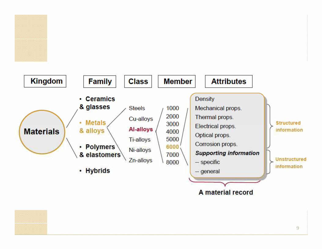
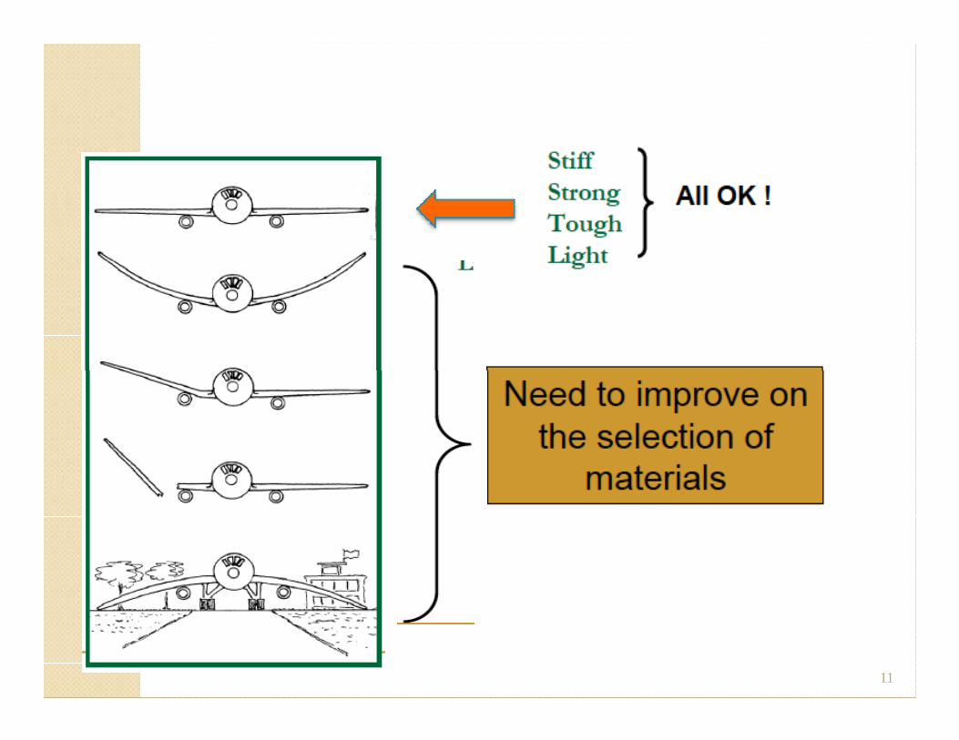
Materials selection
9
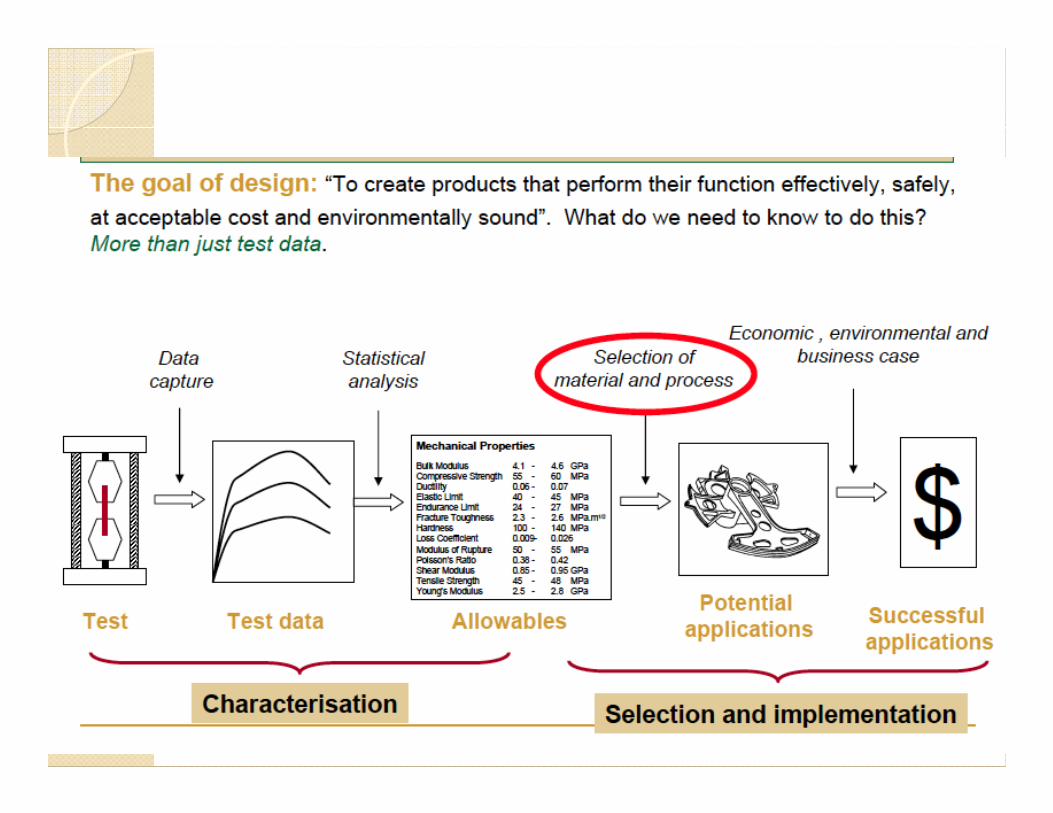
Materials and Design
10
11
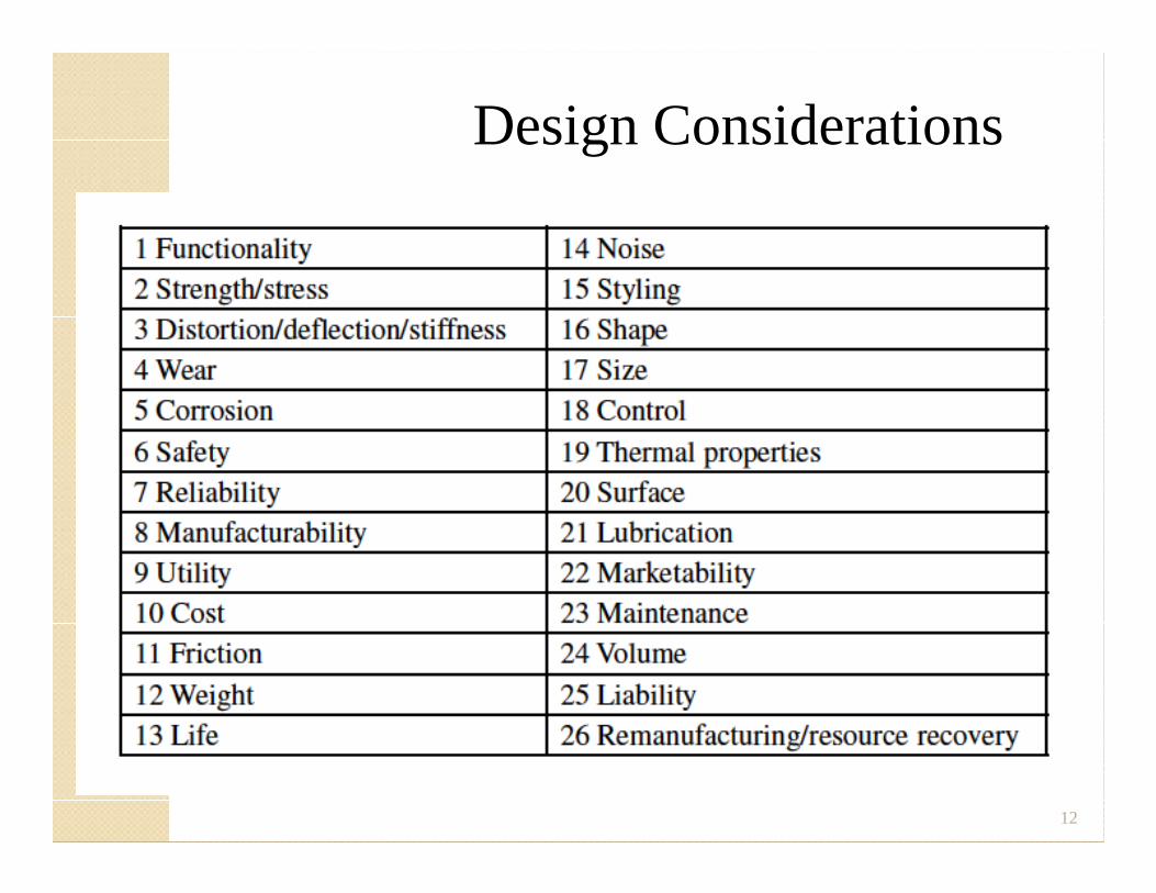
Design Considerations
12
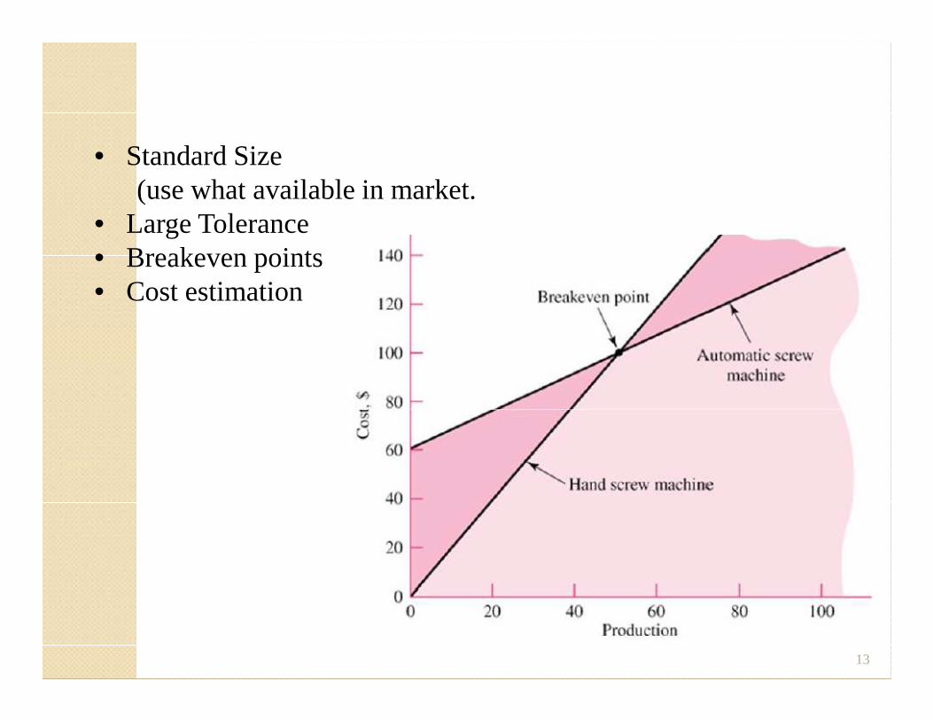
Economics• Standard Size
(use what available in market.• Large Tolerance• Breakeven points• Cost estimation
13
Review of Stresses and StrainsReview of Stresses and StrainsReview of Stresses and StrainsReview of Stresses and Strains
14
1.1 DIRECT OR NORMAL 1.1 DIRECT OR NORMAL STRESSSTRESS
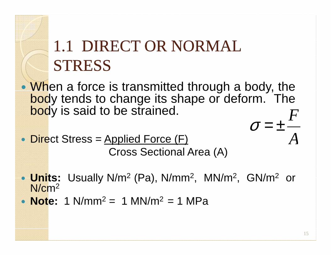
� When a force is transmitted through a body, thebody tends to change its shape or deform. Thebody is said to be strained.
σ = ± F� Direct Stress = Applied Force (F)
Cross Sectional Area (A)
� Units: Usually N/m2 (Pa), N/mm2, MN/m2, GN/m2 orN/cm2
� Note: 1 N/mm2 = 1 MN/m2 = 1 MPa
15
σ = ±A
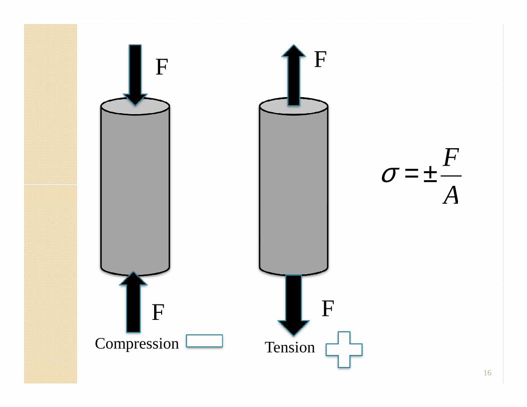
σ = ± F
A
F F
16
TensionCompression
A
F F
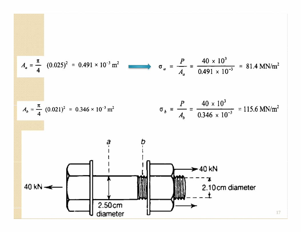
Example
17
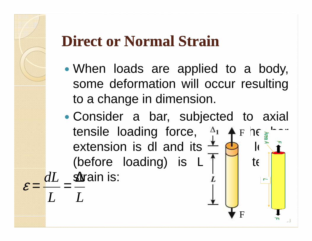
Direct or Normal StrainDirect or Normal Strain
� When loads are applied to a body,some deformation will occur resultingto a change in dimension.
� Consider a bar, subjected to axial� Consider a bar, subjected to axialtensile loading force, F. If the barextension is dl and its original length(before loading) is L, then tensilestrain is:
18
ε = dL
L= ∆
LF
F
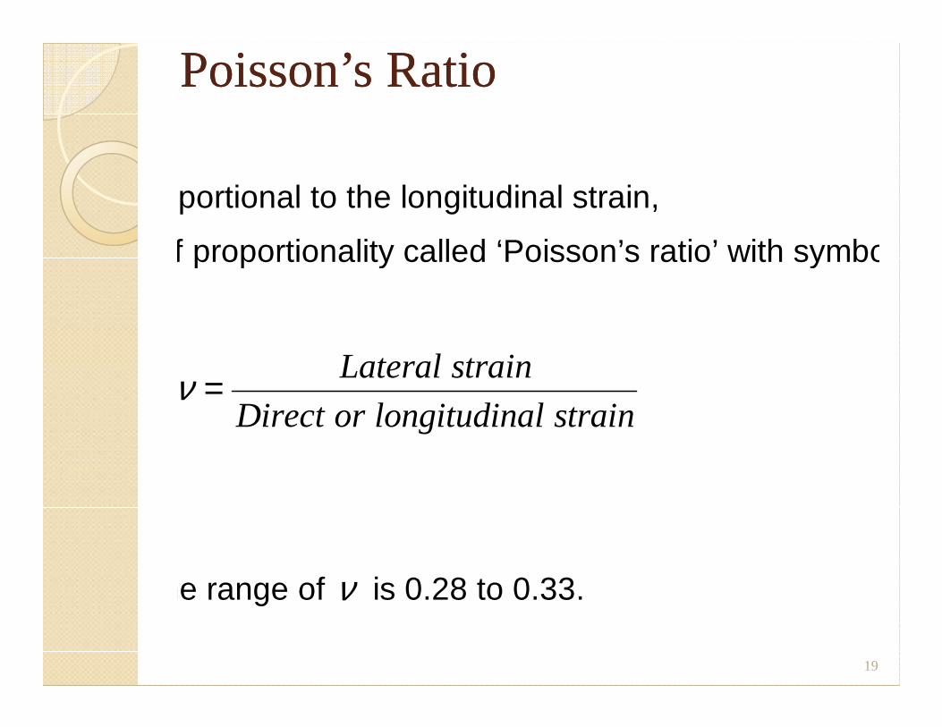
Poisson’s RatioPoisson’s Ratio
Lateral strain is proportional to the longitudinal strain,
with the constant of proportionality called ‘Poisson’s ratio’ with symbol,
Lateral strainν = Lateral strain
Direct or longitudinal strain
For most metals, the range of ν is 0.28 to 0.33.
19
Direct or Normal Strain Direct or Normal Strain
As strain is a ratio of lengths, it is dimensionless.Similarly, for compression by amount, dl: Compressivestrain = - dl/L
20
Note: Strain is positive for an increase in dimension andnegative for a reduction in dimension.
Shear Stress Shear Stress andand
shear Strainshear Strain
21
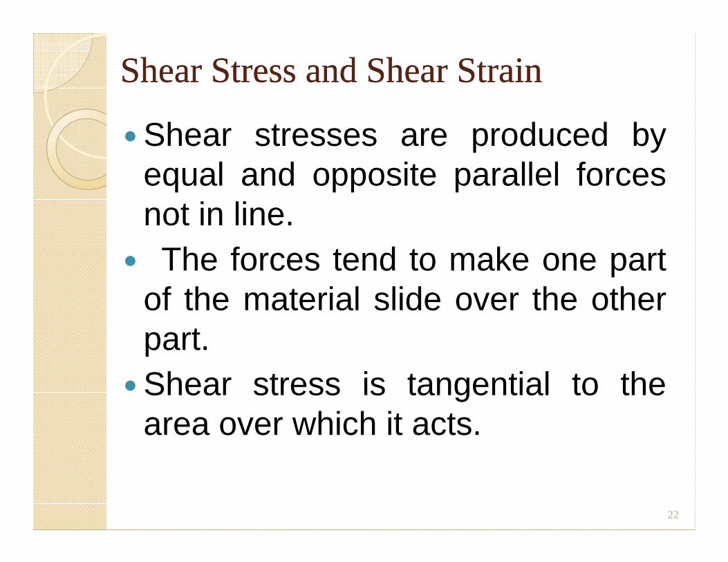
Shear Stress and Shear StrainShear Stress and Shear Strain
� Shear stresses are produced byequal and opposite parallel forcesnot in line.
� The forces tend to make one partof the material slide over the otherof the material slide over the otherpart.
� Shear stress is tangential to thearea over which it acts.
22
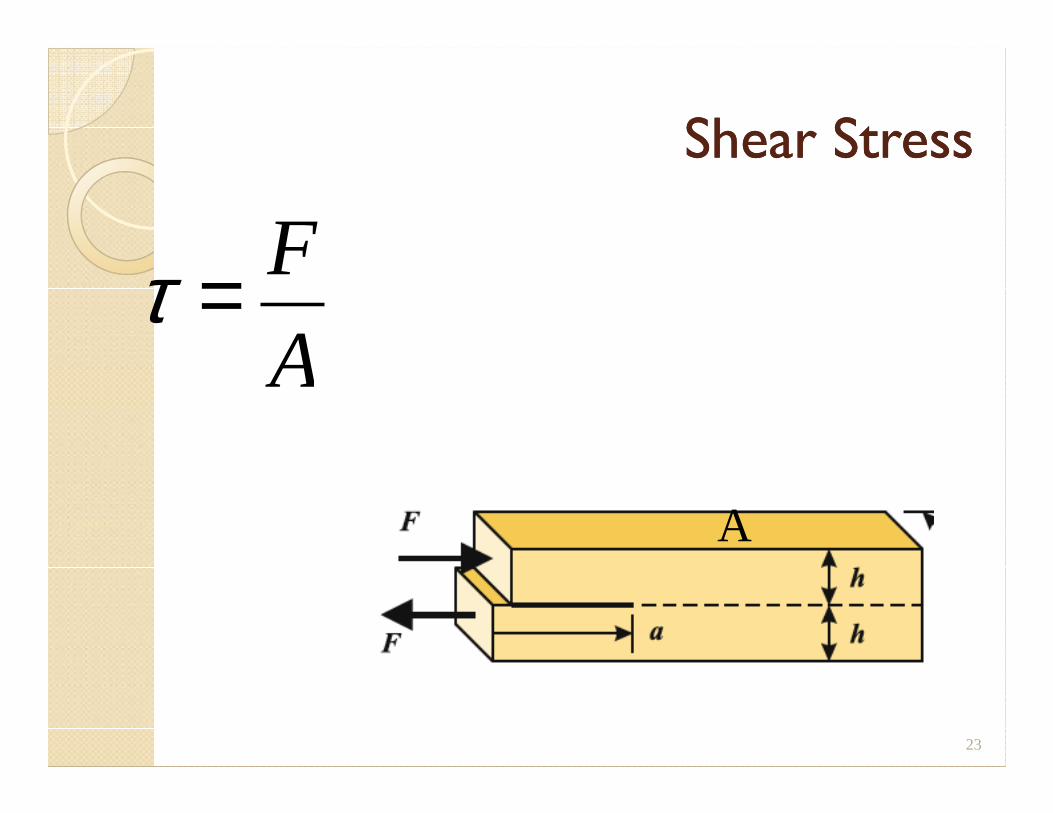
Shear StressShear Stress
τ = F
A
23
A
Shear Stress and Shear Strain Shear Stress and Shear Strain ..
FD D’C C’
L
x
24
A B
L
φ
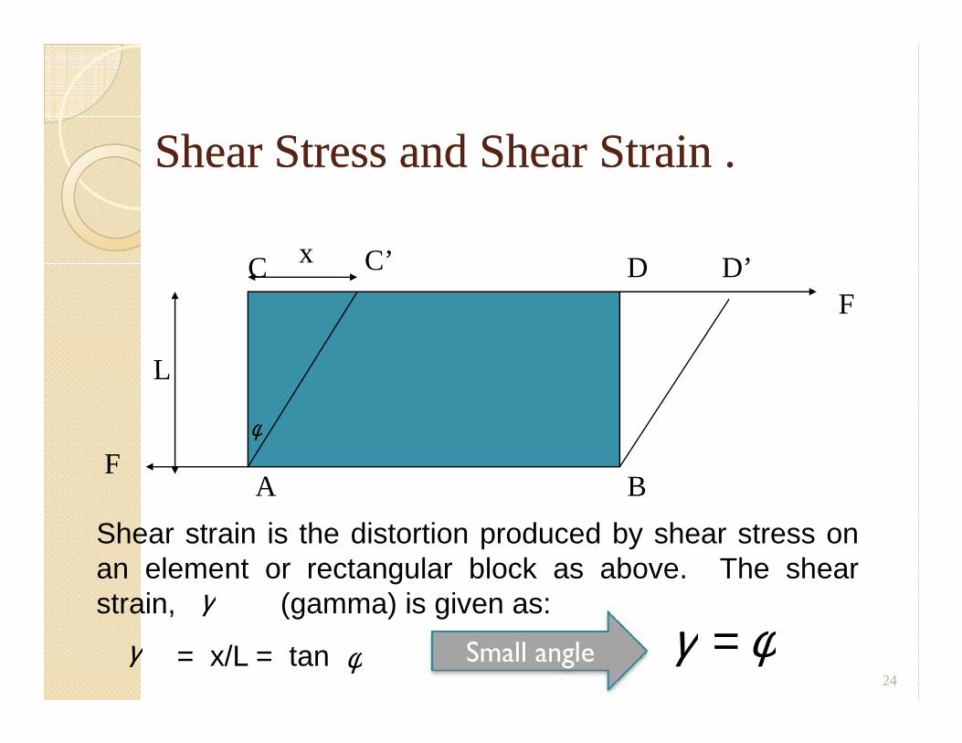
Shear strain is the distortion produced by shear stress onan element or rectangular block as above. The shearstrain, (gamma) is given as:
= x/L = tanγ φ
γ
F
γ φ=Small angle
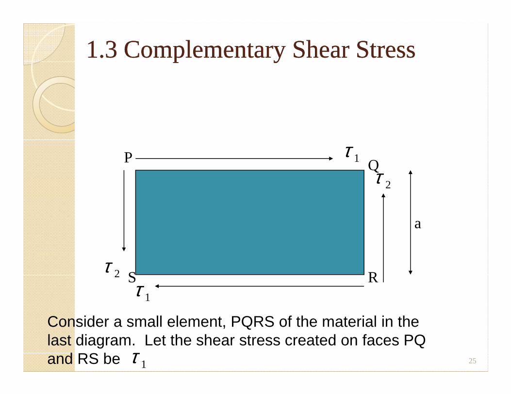
1.3 Complementary Shear Stress1.3 Complementary Shear Stress
τ 1
τ 2
P Q
25
a
τ 1
τ 2 S R
Consider a small element, PQRS of the material in the last diagram. Let the shear stress created on faces PQ and RS be τ 1
Volumetric Strain Contd.Volumetric Strain Contd.
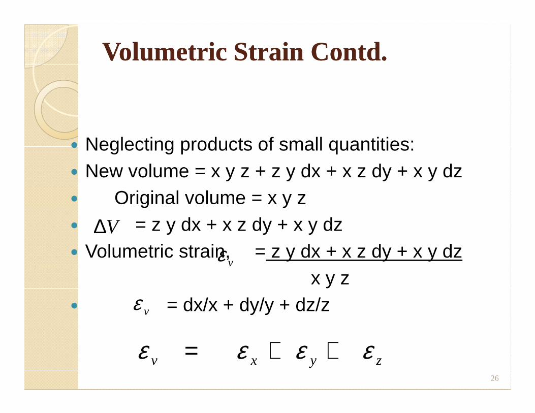
� Neglecting products of small quantities:� New volume = x y z + z y dx + x z dy + x y dz� Original volume = x y z� Original volume = x y z� = z y dx + x z dy + x y dz� Volumetric strain, = z y dx + x z dy + x y dz
x y z� = dx/x + dy/y + dz/z
26
∆V
ε v
ε v
ε ε ε εv x y z= + +
1.5 Elasticity and Hooke’s Law1.5 Elasticity and Hooke’s Law
� All solid materials deform when they are stressed, and as stress is increased, deformation also increases.
� If a material returns to its original size and shape on removal of load causing shape on removal of load causing deformation, it is said to be elastic.
� If the stress is steadily increased, a point is reached when, after the removal of load, not all the induced strain is removed.
� This is called the elastic limit.
27
Hooke’s LawHooke’s Law
� States that providing the limit ofproportionality of a material is notexceeded, the stress is directly proportionalto the strain produced.
� If a graph of stress and strain is plotted as� If a graph of stress and strain is plotted asload is gradually applied, the first portion ofthe graph will be a straight line.
� The slope of this line is the constant ofproportionality called modulus of Elasticity,E or Young’s Modulus.
� It is a measure of the stiffness of a material.
28
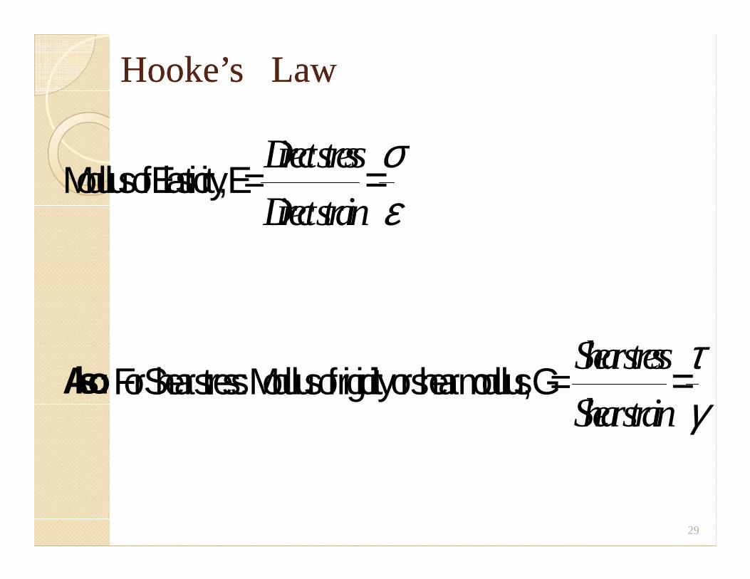
Hooke’s LawHooke’s Law
Modulus of Elasticity, E = Directstress
Directstrain=σε
Also: For Shear stress: Modulus of rigidity or shear modulus, G = Shearstress
Shearstrain=τγ
29
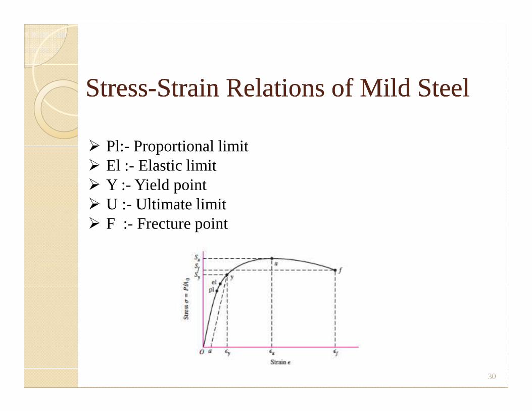
StressStress--Strain Relations of Mild SteelStrain Relations of Mild Steel
� Pl:- Proportional limit� El :- Elastic limit� Y :- Yield point� U :- Ultimate limit
30
� U :- Ultimate limit� F :- Frecture point
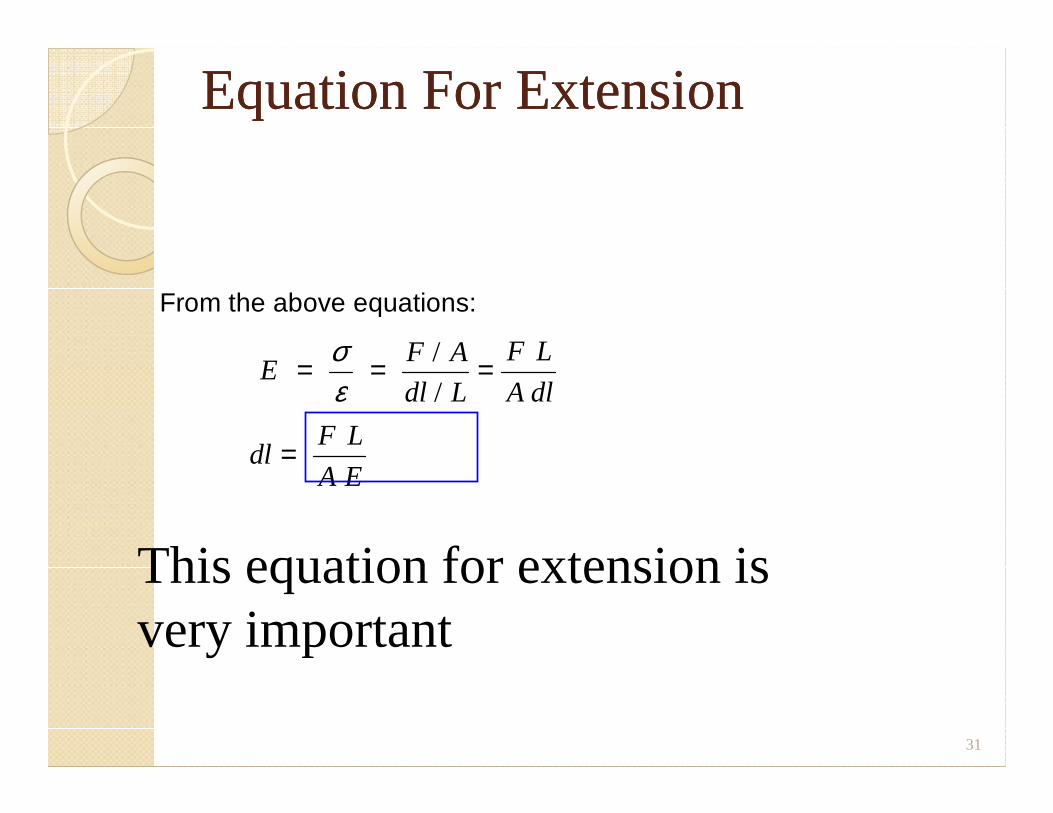
Equation For ExtensionEquation For Extension
From the above equations:
EF A
dl L
F L
A dl= = =σ
ε/
/
dl L A dl
dlF L
A E=
ε /
31
This equation for extension is very important
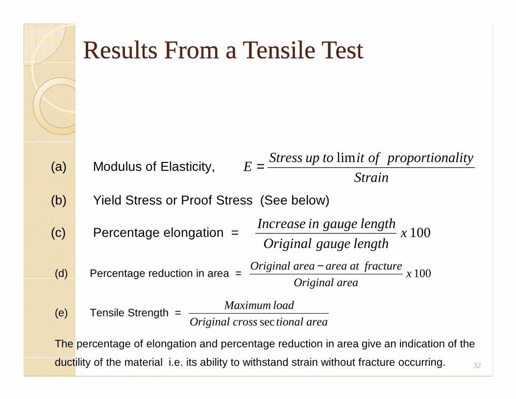
Results From a Tensile TestResults From a Tensile Test
(a) Modulus of Elasticity, EStress up to it of proportionality
Strain= lim
(b) Yield Stress or Proof Stress (See below) (b) Yield Stress or Proof Stress (See below)
(c) Percentage elongation = Increase in gauge length
Original gauge lengthx 100
32
(d) Percentage reduction in area = Original area area at fracture
Original areax
−100
(e) Tensile Strength = Maximum load
Original cross tional areasec
The percentage of elongation and percentage reduction in area give an indication of the
ductility of the material i.e. its ability to withstand strain without fracture occurring.
Proof StressProof Stress
� High carbon steels, cast iron and most ofthe non-ferrous alloys do not exhibit a welldefined yield as is the case with mild steel.
� For these materials, a limiting stress calledproof stress is specified, corresponding to aproof stress is specified, corresponding to anon-proportional extension.
� The non-proportional extension is aspecified percentage of the original lengthe.g. 0.05, 0.10, 0.20 or 0.50%.
33
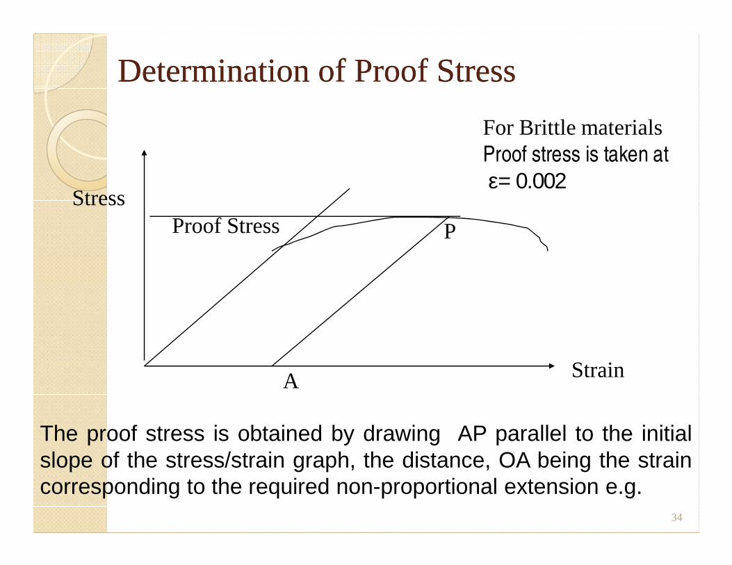
Determination of Proof StressDetermination of Proof Stress
PProof StressStress
For Brittle materialsProof stress is taken at
ε= 0.002
34
The proof stress is obtained by drawing AP parallel to the initialslope of the stress/strain graph, the distance, OA being the straincorresponding to the required non-proportional extension e.g.
A Strain
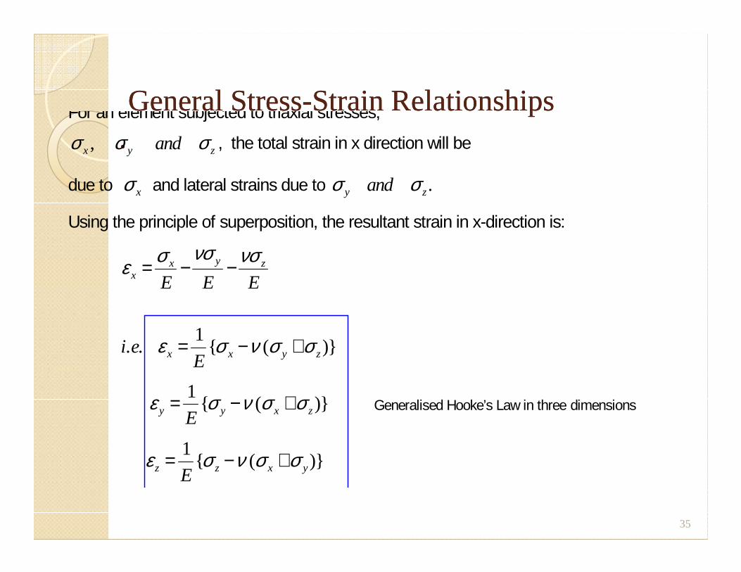
General StressGeneral Stress--Strain RelationshipsStrain Relationships..
For an element subjected to triaxial stresses,
σ σ σx y zand, , the total strain in x direction will be
due to σ x and lateral strains due to σ σy zand .
Using the principle of superposition, the resultant strain in x-direction is:
ε σ νσ νσx
x y z
E E E= − −
ε σ ν σ σx x y z
E E E
i eE
= − +. . { ( )}1
ε σ ν σ σy y x zE= − +1
{ ( )} Generalised Hooke’s Law in three dimensions
ε σ ν σ σz z x yE= − +1
{ ( )}
35
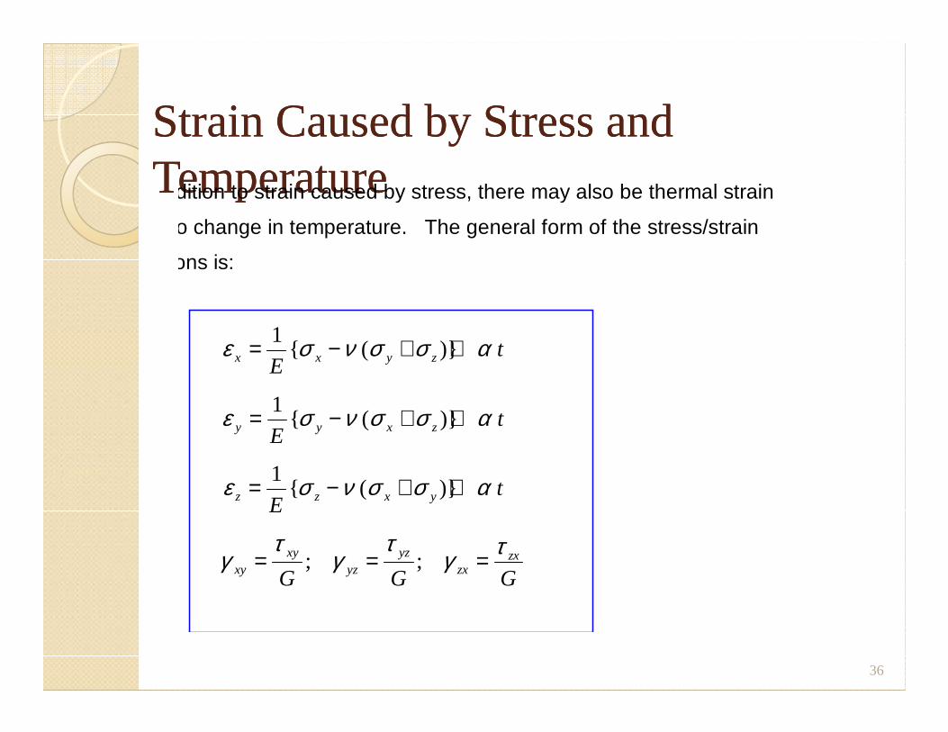
Strain Caused by Stress and Strain Caused by Stress and TemperatureTemperatureIn addition to strain caused by stress, there may also be thermal strain
due to change in temperature. The general form of the stress/strain
relations is:
ε σ ν σ σ αx x y zEt= − + +1
{ ( )} E
ε σ ν σ σ αy y x zEt= − + +1
{ ( )}
ε σ ν σ σ αz z x yEt= − + +1
{ ( )}
γτ
γτ
γ τxy
xyyz
yzzx
zx
G G G= = =; ;
36
Stress in beamsStress in beamsStress in beamsStress in beams
37
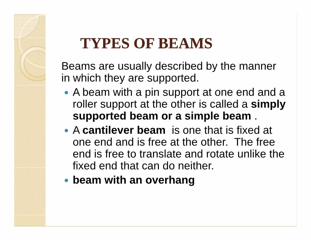
TYPES OF BEAMS TYPES OF BEAMS Beams are usually described by the manner in which they are supported. � A beam with a pin support at one end and a
roller support at the other is called a simply supported beam or a simple beam . supported beam or a simple beam .
� A cantilever beam is one that is fixed at one end and is free at the other. The free end is free to translate and rotate unlike the fixed end that can do neither.
� beam with an overhang
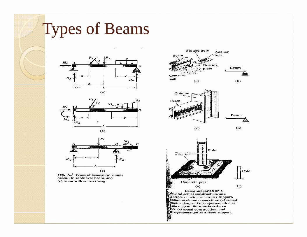
Types of BeamsTypes of Beams
40

SHEAR FORCES AND BENDING SHEAR FORCES AND BENDING MOMENTS MOMENTS ..
� The resultant of the stresses must be such as to maintain the equilibrium of the free body.
� The resultant of the stresses acting on thecross section can be reduced to a shear forcecross section can be reduced to a shear forceV and a bending moment M.
� The stress resultants in staticallydeterminate beams can be calculated fromequations of equilibrium.
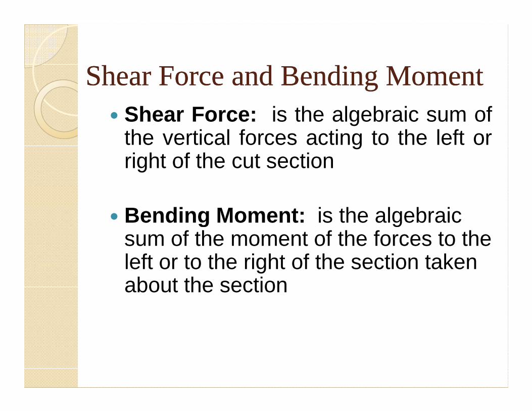
Shear Force and Bending MomentShear Force and Bending Moment� Shear Force: is the algebraic sum of
the vertical forces acting to the left orright of the cut section
Bending Moment: is the algebraic � Bending Moment: is the algebraic sum of the moment of the forces to the left or to the right of the section taken about the section
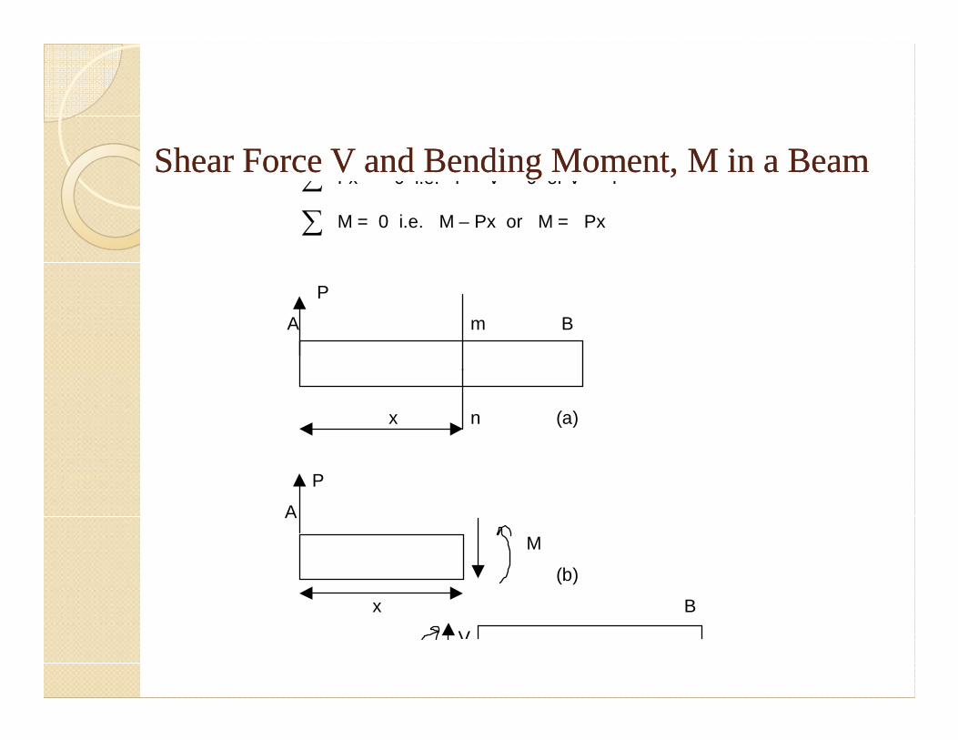
Shear Force V and Bending Moment, M in a BeamShear Force V and Bending Moment, M in a Beam ∑ Fx = 0 i.e. P – V = 0 or V = P
∑ M = 0 i.e. M – Px or M = Px
P
A m B
x n (a)
P
A
M
(b)
x B
V
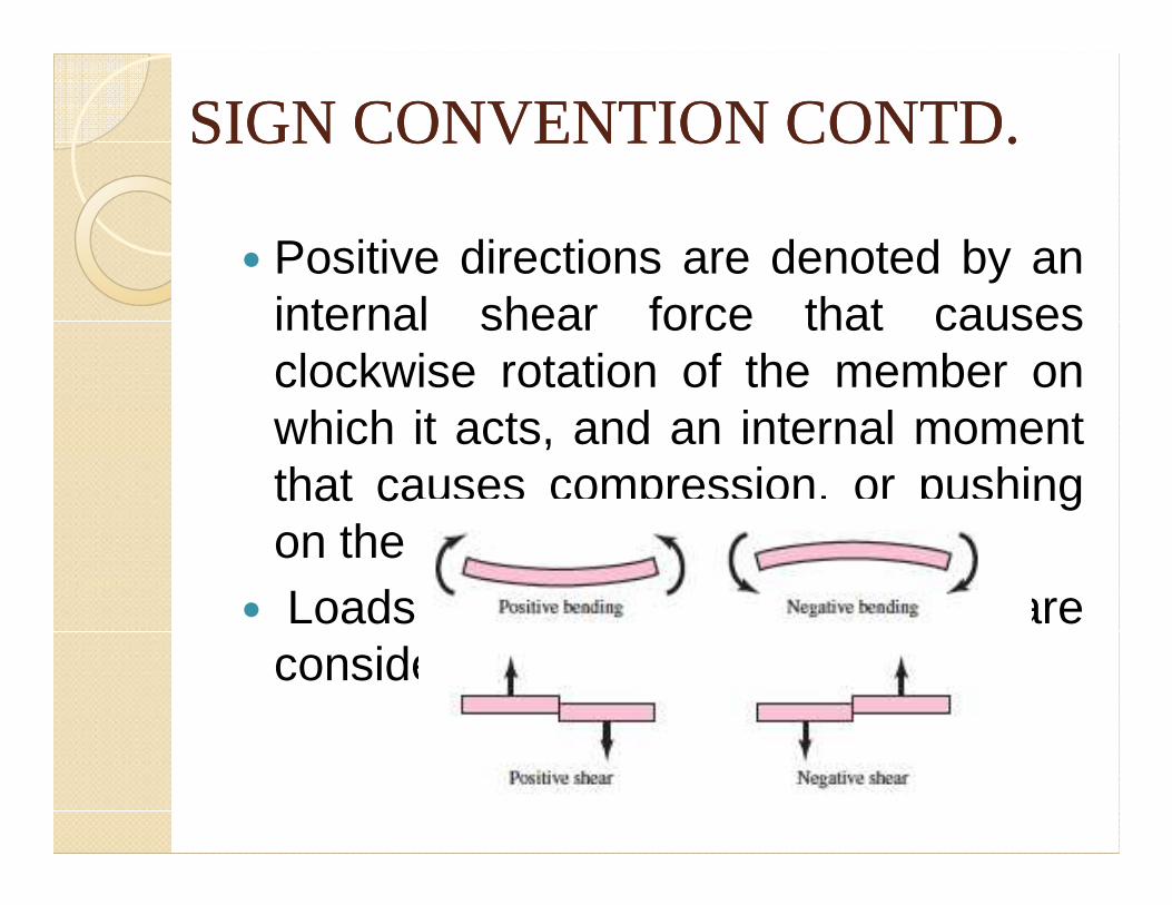
SIGN CONVENTION CONTD.SIGN CONVENTION CONTD.
� Positive directions are denoted by aninternal shear force that causesclockwise rotation of the member onwhich it acts, and an internal momentwhich it acts, and an internal momentthat causes compression, or pushingon the upper arm of the member.
� Loads that are opposite to these areconsidered negative.
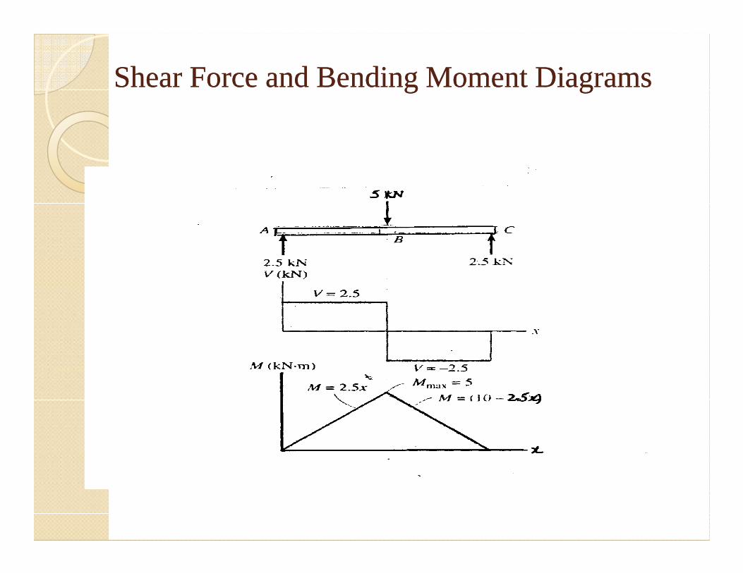
Shear Force and Bending Moment DiagramsShear Force and Bending Moment Diagrams
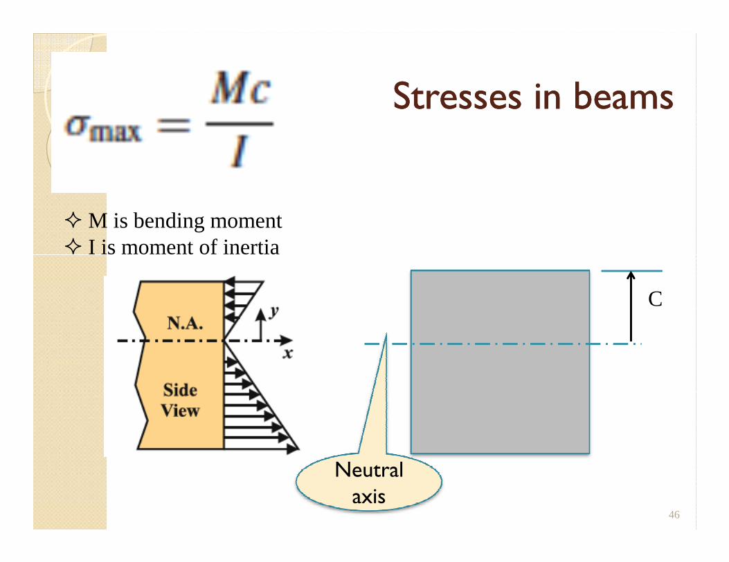
Stresses in beamsStresses in beams
� M is bending moment� I is moment of inertia
46
C
Neutral axis
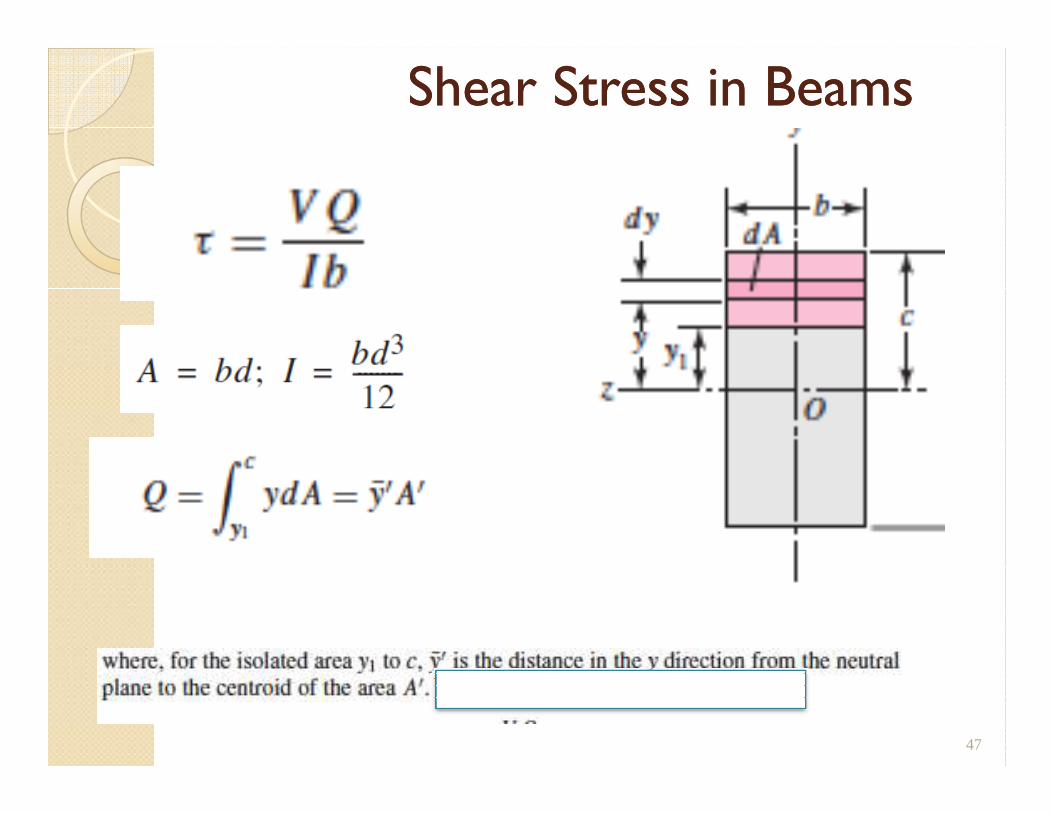
Shear Stress in BeamsShear Stress in Beams
47
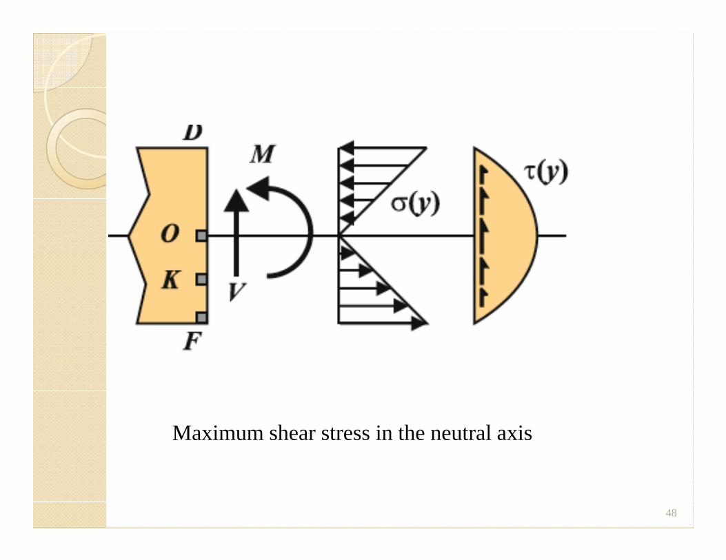
48
Maximum shear stress in the neutral axis
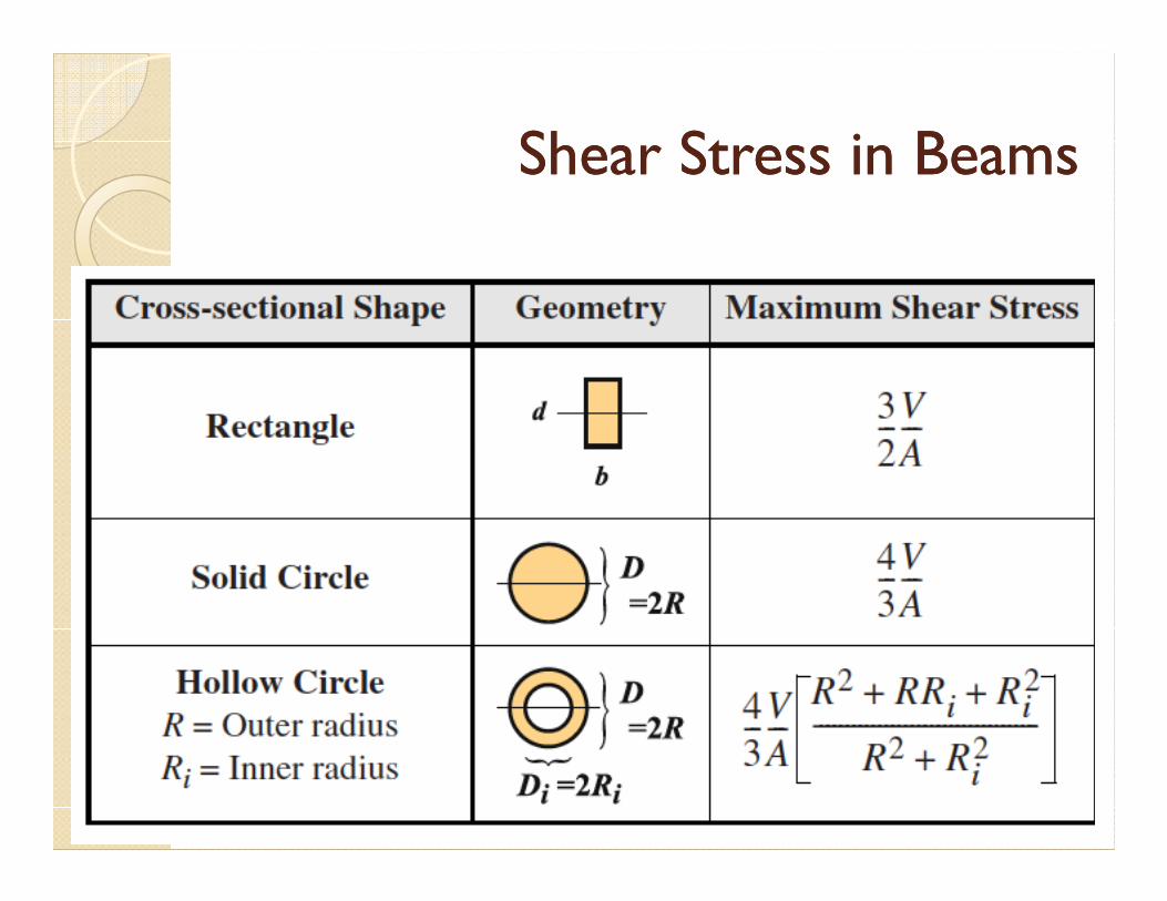
Shear Stress in BeamsShear Stress in Beams
49
TorsionTorsionTorsionTorsion
50
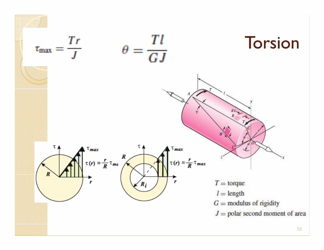
TorsionTorsion
51
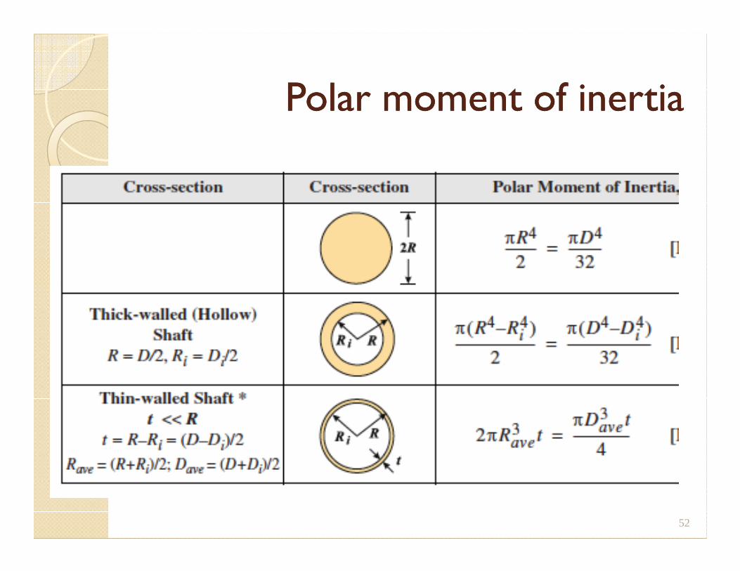
Polar moment of inertiaPolar moment of inertia
52
Pressure VesselsPressure VesselsPressure VesselsPressure Vessels
53
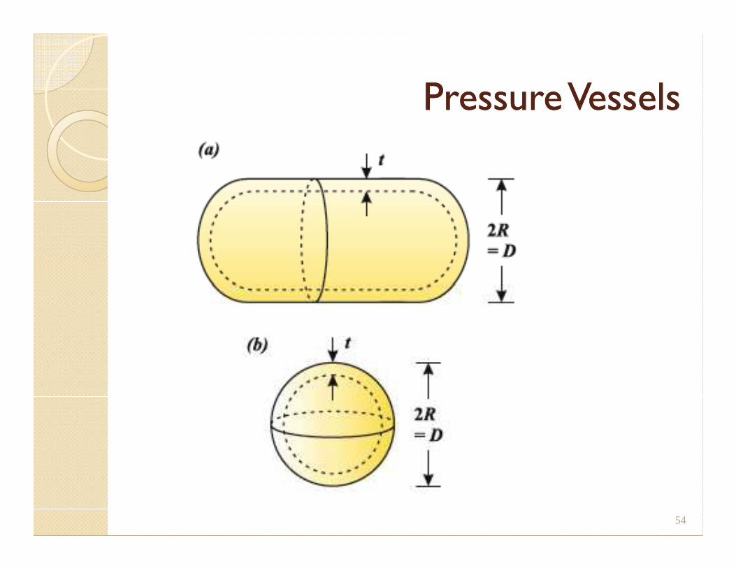
Pressure VesselsPressure Vessels
54
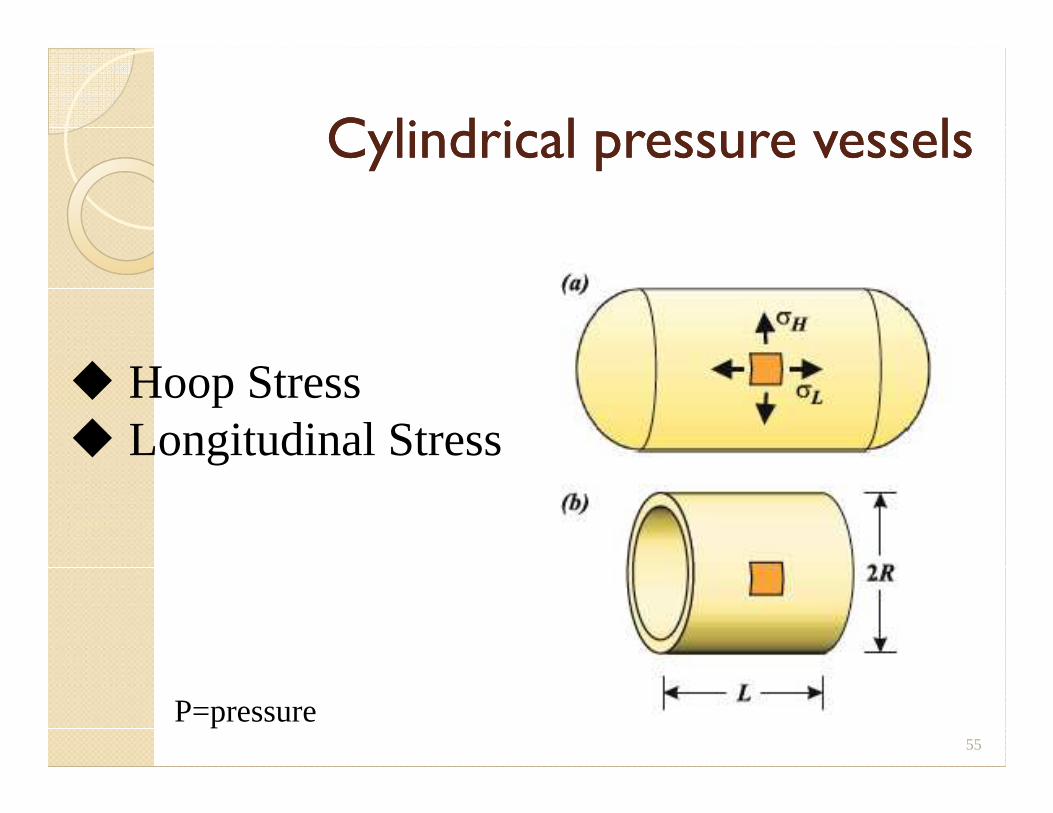
Cylindrical pressure vessels Cylindrical pressure vessels
� Hoop Stress
55
� Hoop Stress� Longitudinal Stress
P=pressure
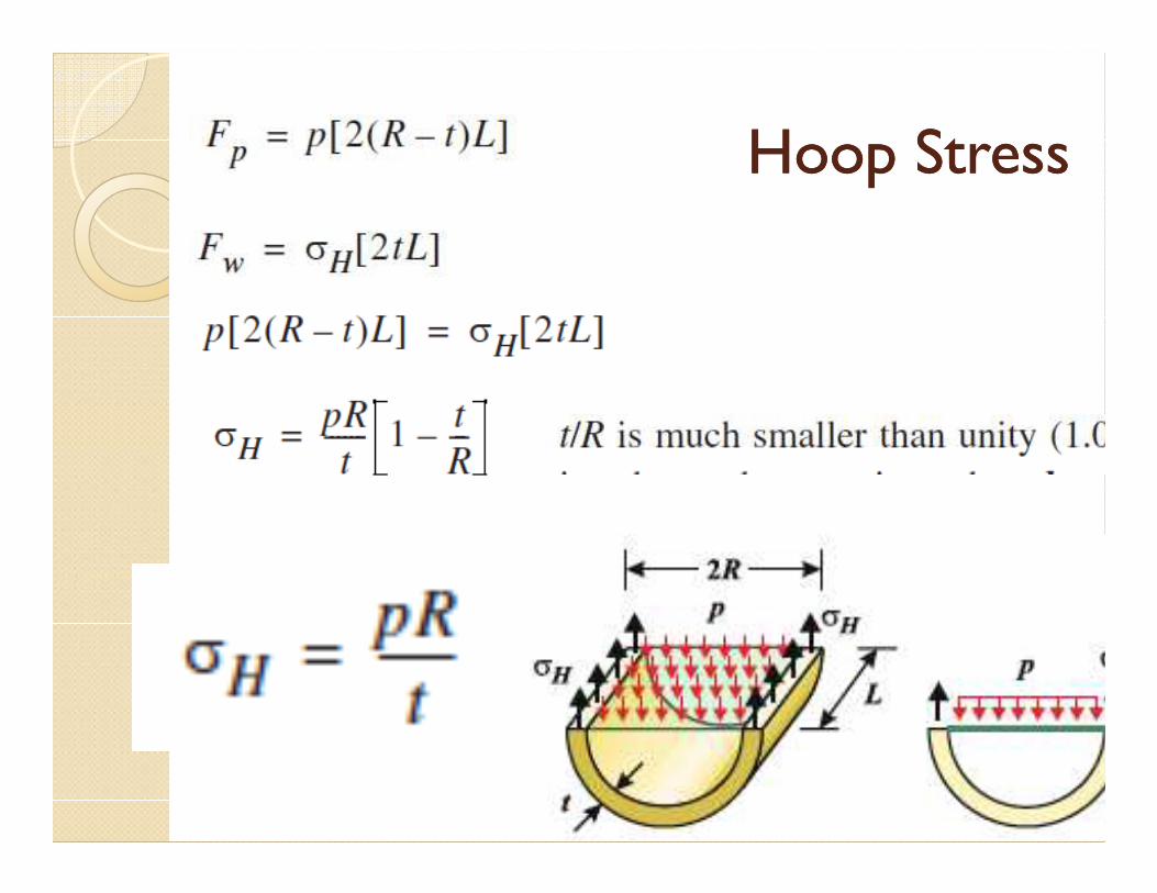
Hoop StressHoop Stress
56
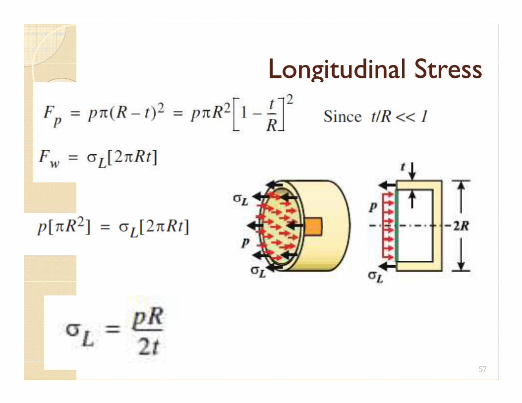
Longitudinal StressLongitudinal Stress
57
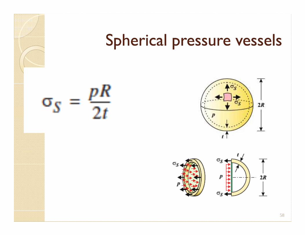
Spherical pressure vesselsSpherical pressure vessels
58


