14

Scientia Iranica B (2013) 20(1), 1{14
Sharif University of TechnologyScientia Iranica
Transactions B: Mechanical Engineeringwww.scientiairanica.com
Design of mixed refrigerant cycle for low temperatureprocesses using a thermodynamic approach
M. Ma�a, B. Ghorbanib;�, M. Amidpourb, S.M. Mousavi Naynianb
a Department of Mechanical Engineering, Imam Khomeini International University, Qazvin, P.O. Box 34149-16818, Iran.b Faculty of Mechanical Engineering, K.N.Toosi University of Technology, Tehran, P.O. Box 19395-1999, Iran.
Received 20 June 2012; accepted 11 March 2013
KEYWORDSMixed refrigerantcycle; Lowtemperatureprocesses; Systematicdesign; Optimaloperating conditions;Optimal arrangement.
Abstract. Minimizing the work consumed by a refrigeration system is an e�ectivemeasure for reducing the cost of products in sub-ambient chemical processes, such as inole�n plants. A recent advancement has been the introduction of mixed working uids inrefrigeration systems in place of pure working uids. Due to the lack of a systematic designmethod for the Mixed Refrigerant Cycle (MRC), conventional approaches are largely trial-and-error and, therefore, operations can be under far from optimal conditions. In this paper,a novel method for systematic design of MRCs is presented, which combines the bene�tsof the thermodynamics approach and mathematical optimization. Based on the successof the proposed systematic method for the optimal selection of refrigerant compositionand operating pressures, the method is extended to give optimal arrangement of the cyclecomponents. The procedure is demonstrated using a case study of the design of MRC fora typical ole�n plant.c 2013 Sharif University of Technology. All rights reserved.
1. Introduction
For many years, cascade refrigeration cycles havebeen used to cool and liquefy feed streams in sub-ambient processes, such as ole�n (ethylene recovery)plants. Such cascade cycles have commonly includeda plurality of individual refrigerants having decreasingatmospheric boiling points, each of which is circulatedin a closed cycle to heat exchange with the feedstreams. Unfortunately, the use of such individualrefrigerants requires a very large number of separateheat exchangers, pumps, compressors and associatedpipes and valves for the separate, closed loops of eachstate. Even more importantly, the cooling curvesof individual refrigerants do not closely match thecontinuous cooling curve of the feed stream, and thisis of particular importance with respect to the lowtemperature end of the cascade system, where a very
* Corresponding author.E-mail: address: [email protected]
substantial amount of power is wasted by this inherentine�ciency in such a cascade system [1].
Minimizing the work consumed by the refrigera-tion cycle is the most e�ective measure for reducing thecost of products of sub-ambient chemical processes. Arecent advancement has been the introduction of mixedworking uids in refrigeration systems in place of pureworking uids. Refrigeration systems, known as MixedRefrigerant Cascades, which can reach temperaturesas low as 120 K, are under development in manyparts of the world. This refrigeration method, witha multi-component mixture, has demonstrated highperformance in low temperature ranges [2].
Nowadays, the MRC is widely used in commercialnatural gas liquefaction �elds whose liquefaction capac-ities are very large. The simpli�cation of the compres-sion and heat exchange processes in such a cycle mayo�er the potential for reduced capital expenditure, incomparison with conventional cascade cycles [3,4].
The concept of using a mixture as a refrigeranthas been around for a long time. The mixed refrigerant

2 M. Ma� et al./Scientia Iranica, Transactions B: Mechanical Engineering 20 (2013) 1{14
cycle was patented by Podbeilniak [5], which utilizesthree stages of throttling, and a single compressorin a closed cycle. Thereafter, several MRCs werepatented regarding gas liquefaction and separationapplications [1,6-9]. Also, many investigations areavailable in open literature on the performance ofMRCs in di�erent low temperature applications [2,10-13].
The fundamental aspects of mixed refrigerantprocesses, though very innovative, have not receiveddue attention in the open literature, in view of com-mercial interests. It is di�cult to piece together theexisting information to choose an appropriate processand an optimum composition for a given application.Venkatarathnam [14] has recently reviewed the fun-damental aspects of mixed refrigerant processes, theiradvantages, the methods for optimizing the refrigerantcomposition and the performance of di�erent processeswith di�erent nitrogen-hydrocarbon mixtures.
In sub-ambient processes, the design of refrig-eration systems is a major concern for energy con-sumption and capital investment. The synthesis andoptimization of MRCs for low temperature processes iscomplex, due to the large number of design options. Inthe design of mixed refrigeration systems for chemicalprocesses, the main key issues are: composition ofthe mixed refrigerant, operating pressures (suction anddischarge pressure of compressors), cycle con�guration,and heat integration between refrigeration systems andprocess streams to achieve close matching of the hotand cold composite curves. There is no research in theliterature on the designing of MRCs for low tempera-ture industrial chemical processes using a systematicmethodology that includes all the above mentionedaspects. The objective of this work is to present amethodology with graphical and numerical tools for theanalysis, design and optimization of MRC for complexlow temperature processes.
2. Design of MRC with a given con�guration
In the current paper, we concentrate on MRC designfor complex low temperature chemical processes. Asa typical example of low temperature processes, wehave chosen an ethylene process (ole�n plant). Inan ethylene recovery process, a feed gas, comprisinghydrogen, methane, ethane, ethylene, propane, propy-lene, and minor amounts of other light components,is compressed, cooled, and partially condensed insingle stage condensers or, alternatively, in one ormore dephlegmators, which imparts several stages ofseparation during the condensation step. The con-densate is separated from lighter gases and is passedto one or more demethanizer columns, which recoverlight gas overheads comprised of chie y methane andhydrogen, and a bottoms stream rich in C2 and C3
hydrocarbons. This hydrocarbon stream is furtherfractionated to yield a high purity ethylene product, anethane-rich byproduct, and a stream of C3 and heavierhydrocarbons.
Essentially, all ole�n plants use an ethylene-propylene cascade refrigeration system to provide themajor portion of refrigeration required in the ole�nplant. Most of the propylene (high level) refrigerationis utilized at several pressure/temperature levels in theinitial feed precooling and fractionation sections of theplant to cool the feed from ambient temperature toabout -35�C and to condense the ethylene refrigerantat about -30�C. Similarly, the ethylene (low level)refrigeration is utilized at several pressure/temperaturelevels in the cryogenic section of the plant to cool thefeed from -35�C to about -100�C, in order to condensethe bulk of the ethylene in the form of liquid feedsto a demethanizer column, and, in the demethanizercolumn, an overhead condenser at about -101�C to pro-vide re ux to that column. Refrigeration below -101�C,to condense the remaining ethylene from the feed, isprovided primarily by the work of expansion or theJoule-Thomson expansion of rejected light gases, H2and methane, and/or by vaporization of the methanerefrigerant which has been condensed by the ethylenerefrigerant. The work of expansion or Joule-Thomsonexpanded gases is normally used as fuel and consistsprimarily of the overhead vapor from the demethanizercolumn (mostly methane) and any uncondensed feedgas (mostly H2 and methane) which is not processed inthe H2 recovery section of the ole�n plant.
The power consumption is always high in an ole�nplant refrigeration system. Therefore, minimizing thework consumed by the refrigeration cycle is the moste�ective measure to reduce production costs in ole�nplants.
2.1. Description of cascade refrigerationsystem
The cascade refrigeration system of the ole�n plantanalyzed in this study consists of ambient cooling waterat near ambient temperature, closed cycle propyleneand ethylene systems, and Joule-Thomson expansionof rejected light gases from the demethanizer columnoverhead vapor, and uncondensed feed gas in the H2recovery section of the plant. Propylene refrigera-tion is utilized at several temperature levels (+5, -20and -35�C) to cool and heat the feed in the initialfractionation sections of the plant. Similarly, theethylene refrigeration is utilized at several temperaturelevels (-65�C and -101�C) to cool the feed in thecryogenic section of the plant. Detailed description ofthe ethylene-propylene cascade refrigeration system hasbeen presented in our previous work [15].
Figure 1 shows the ow diagram of an ethy-lene refrigeration cycle. Ethylene refrigerant vapors

M. Ma� et al./Scientia Iranica, Transactions B: Mechanical Engineering 20 (2013) 1{14 3
Figure 1. Flow diagram of ethylene refrigeration cycle.
discharged from the compressor are desuperheatedand condensed in E-504, E-505, E-506 and E-507,utilizing cooling water and 5�C, -20�C and -35�Cliquid propylene refrigerant, respectively. As seenfrom Figure 1, in addition to the ethylene refrigerant,the cooling potential of the hydrogen rich gas, tailgas and regeneration gas streams has been used forcooling the feed stream in the heat exchanger, E-305.These cold process streams are provided by the Joule-Thomson expanded light overhead product from thedemethanizer column and any hydrogen and methanewhich is not processed in the hydrogen recovery section.
Figure 2 shows the refrigeration system matchedagainst the GCC (Grand Composite Curve) of theole�n plant separation process analyzed in this
Figure 2. GCC of the refrigeration system analyzed inthis work [15].
work [15]. Sometimes, the refrigeration levels are�tted against a nearly at portion of the GCC (e.g.propylene refrigeration levels in Figure 2). In thiscase, the pure refrigerants and azeotropic mixtures arethe best options because of isothermal vaporizationin the evaporators. Sometimes, the refrigerant levelneeds to be �tted against a slope of the GCC, asethylene refrigeration levels shown in Figure 2. Inthis case, there is a degree of freedom in choosingthe level of refrigeration [3]. For example, the GCCof the separation process analyzed in this work showsthat having multiple stage evaporations for an ethylenerefrigeration cycle makes the average temperature dif-ference between the process streams and the refrigerantsmall. This results in smaller exergy destruction inthe E-308 and E-305 evaporators, since the greaterthe temperature di�erence, the greater the exergydestruction. As the number of evaporation stagesincreases, the exergy destruction decreases. However,adding more stages means additional equipment cost,and more than two stages for an ethylene cycle in anole�n plant is not justi�ed [16].
2.2. Developed MRCs for providing low levelrefrigeration
Going from the two-stage evaporation (including -65�Cand -101�C levels) in the ethylene cycle, as shown inFigure 2, to a multiple-stage one, saves power, with anadditional level of complexity, because of the restrictedworking range over which it can operate. The workingrange of refrigerant uids can be extended and modi�ed
4 M. Ma� et al./Scientia Iranica, Transactions B: Mechanical Engineering 20 (2013) 1{14
by using a mixture rather than a pure component. AnMRC uses a mixture as a refrigerant instead of a purerefrigerant. Unlike pure refrigerants, the temperatureand vapour and liquid composition of non-azeotropicmixtures do not remain constant at constant pressureas the refrigerants evaporate or condense [3].
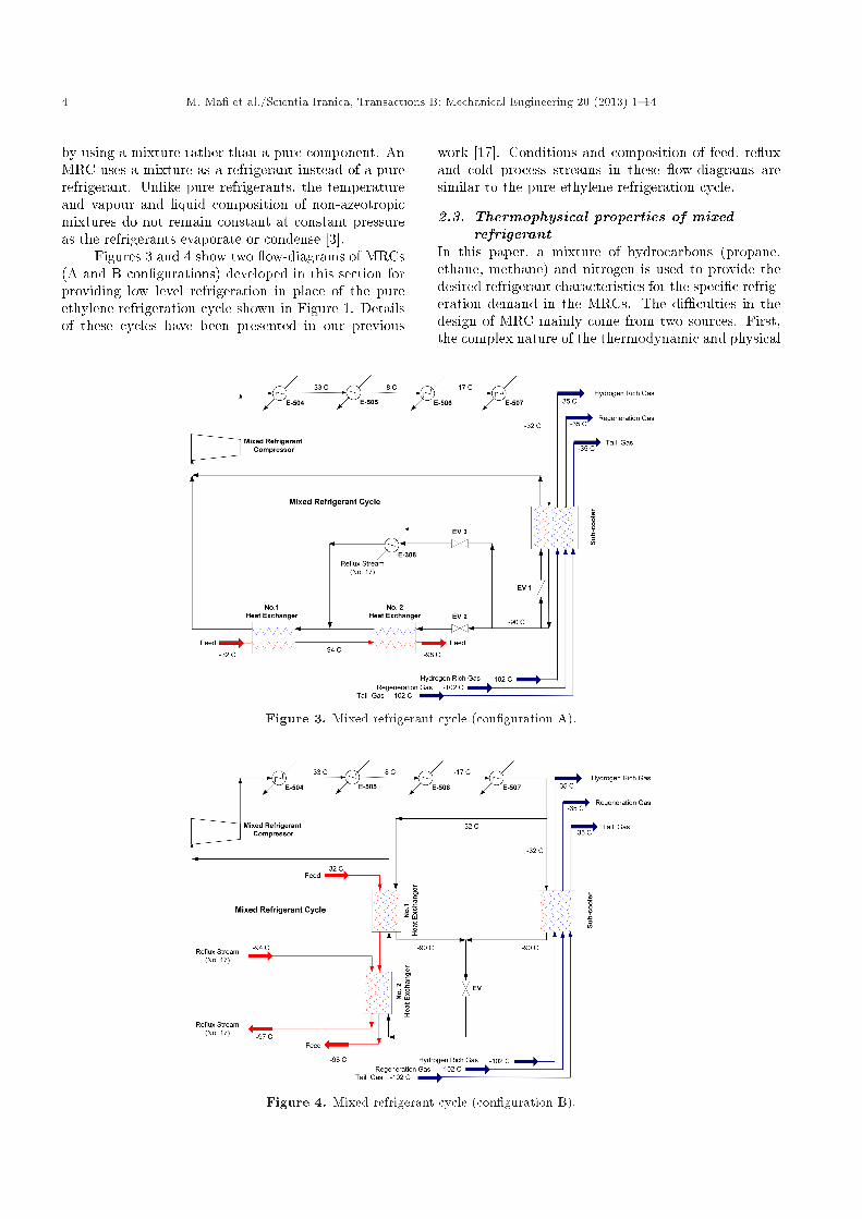
Figures 3 and 4 show two ow-diagrams of MRCs(A and B con�gurations) developed in this section forproviding low level refrigeration in place of the pureethylene refrigeration cycle shown in Figure 1. Detailsof these cycles have been presented in our previous
work [17]. Conditions and composition of feed, re uxand cold process streams in these ow-diagrams aresimilar to the pure ethylene refrigeration cycle.
2.3. Thermophysical properties of mixedrefrigerant
In this paper, a mixture of hydrocarbons (propane,ethane, methane) and nitrogen is used to provide thedesired refrigerant characteristics for the speci�c refrig-eration demand in the MRCs. The di�culties in thedesign of MRC mainly come from two sources. First,the complex nature of the thermodynamic and physical
Figure 3. Mixed refrigerant cycle (con�guration A).
Figure 4. Mixed refrigerant cycle (con�guration B).

M. Ma� et al./Scientia Iranica, Transactions B: Mechanical Engineering 20 (2013) 1{14 5
properties of the mixtures makes the consumption ofMRCs expensive and highly non-linear. Second, isthe small temperature approach between the hot andcold composite curves in multi-stream heat exchangers(the pro�les of evaporation and condensation), and thewide temperature range. This not only increases thedi�culty of modelling for the problem, but also adds tothe non-linearity when carrying out optimization [16].Therefore, an accurate prediction of the phase equilib-rium for vapour-liquid ratios, and values of enthalpyand entropy, is essential for the mixtures.
2.3.1. Vapour-liquid equilibrium calculationsThe equilibrium condition for every component of atwo-phase mixture is expressed by the equality offugacities. For a multicomponent refrigerant, theequilibrium criterion is given by:
fVi = fLi ; i = 1; 2; � � � ; n; (1)
where:fVi fugacity of component i in vapour
phase mixture;
fLi fugacity of component i in liquid phasemixture ;
n number of components in mixture.
The fugacity coe�cient, de�ned as the ratio of fugacityto pressure, of each component in any phase is relatedto pressure, temperature and volume by the followinggeneralized thermodynamic relationship [18,19]:
ln�i =1RT
Z 1V
"�@P@ni
�T;V;nj 6=i
� RTV
#dV � lnZ;
i = 1; 2; � � � ; n; (2)
where:V total volume of n moles of the mixture;ni number of moles of component i;Z compressibility factor of the mixture.
The fugacity coe�cient can be calculated by an equa-tion relating pressure, temperature, volume and com-positions, that is, an equation of state. In general, anyequation of state which provides reliable volumetricdata over the full range of the above integral canbe used to describe the uid phase behaviour. Thesimplest and most highly successful equation is thesemi-empirical two-parameter cubic equation, such asthe Peng-Robinson and Soave-Redlich-Kwong equa-tions [18]. In the present work, the Peng-Robinsonequation of state has been used in calculation of the
phase equilibrium. The Peng-Robinson equation ofstate is given as follows [19,20]:
P =RT� � b �
a�� (� + b) + b (� � b) : (3)
Imposing classical critical point conditions on Eq. (3)and solving for parameters a and b yields:
a = aR2T 2
CPC
; a = 0:45724;
b = bRTCPC
; a = 0:07780; (4)
where the subscript, C, refers to the values at thecritical point, and R is the gas constant.
The temperature dependent parameter, �, isde�ned by:
�=h1+(0:3796+1:5422!�0:2699!2)
�1�pTr�i2 ;
(5)
where ! is the acentric factor.To apply equations of state to multicomponent
systems, their parameters for the mixtures have tobe de�ned by employing some mixing rules. Therandom mixing rule has been recommended for alltwo-constant cubic equations of state. It de�nes theconstant and temperature dependent parameters of thePeng-Robinson equation of state for mixtures as:
P =RT
� � bm �(a�)m
�(� + bm) + bm (� � bm);
(a�)m =Xi
Xj
�yiyjpaiaj�i�j (1� kij)� ;
bm =Xi
[yibi]; (6)
where the indices, i and j, denote the components, andkij is the binary interaction coe�cient. Eq. (6) can berewritten as:
Z3m + (Bm � 1)Z2
m + (Am � 3B2m � 2Bm)Zm
� (AmBm �B2m �B3
m) = 0;
Am =(a�)mP(RT )2 ;
Bm =bmPRT
; (7)
where Z is a constringent factor, A and B are thecoe�cients relating to the gas state parameters andm denotes the mixture.

6 M. Ma� et al./Scientia Iranica, Transactions B: Mechanical Engineering 20 (2013) 1{14
2.3.2. Thermodynamic properties calculationThe Lee-Kesler equation of state is an accurate generalmethod for prediction of the thermodynamic propertiesof non-polar mixtures [20]. In this work, the mixedrefrigerant consists of methane, ethane, propane andnitrogen. Therefore, the Lee-Kesler equation of statehas been used in calculation of the enthalpy and en-tropy of the mixed refrigerant. This model is expressedas:
Z = Z(0) +!!(r)
�Z(r) � Z(0)
�; (8)
where ! is an acentric factor, and 0 and r denote therelevant parameters of simple and reference liquids.
2.4. Optimization algorithmMany factors in uence the performance of a certainMRC, for instance, operating pressures of the cycle(suction and discharge pressures of cycle compressor),the temperature of the refrigerant before expansion,and the mole fraction of mixed refrigerant componentssuch as nitrogen, methane, ethane, and propane, etc.In this work, the optimization problem consists ofthe determination of the optimum parameter valuesthat minimize the power consumption. The objectivefunction is:
min f(x1; x2; � � � ; xn) = W; (9)
where W is the power consumption of the mixed refrig-erant compressor and xi denotes operating parameters,such as the composition of the refrigerant, and thesuction and discharger pressures of the compressor, etc.In fact, it is necessary to take into account all factors,such as initial cost, power consumption, plant area, andthe simplicity of the process, etc., but many of thesefactors are not purely technical [12]. In this paper, onlythe power consumption is considered the optimizationobjective. The constraints are as follows:
� The sum of the mole fractions of the mixed refriger-ant is 1.
� The temperature of the mixed refrigerant at thecompressor inlet is higher than its dew point.
� The temperature di�erence between the hot andcold streams cannot be negative.
In this section, we have proposed a systematic designmethod to �nd the optimum values of operating pres-sure and refrigerant composition, which minimize thepower consumption of MRC with a given con�guration.The basic idea is to �nd a set of refrigerant compo-sitions that give minimum power consumption undergiven pressure levels (high and low operating pressuresof MRCs) and satisfy all above mentioned constraints.Then, the pressure levels of MRC are changed inlimited ranges de�ned by the user, and the procedure
Figure 5. Proposed systematic design method foroptimal selection of refrigerant composition and operatingpressures of MRC with a given con�guration.
of �nding the best refrigerant composition is repeatediteratively. Figure 5 explains the methodology.
As seen from Figure 5, to take the best solutionand avoid being trapped in local optima, a two-phasehybrid method has been developed. The �rst phaseis explorative, employing an Enumerative method toidentify promising areas of the search space. Thebest solution found by the enumerative method is thenre�ned using a pattern search method during a sub-sequent exploitative phase. We selected hybridizationof global and local search algorithms to produce highquality optimal solution, although computational timeis relatively expensive.
It should be mentioned that an important featureof the proposed method is to ensure heat integrationbetween the refrigeration system and process streams.

M. Ma� et al./Scientia Iranica, Transactions B: Mechanical Engineering 20 (2013) 1{14 7
It is guaranteed by combining the cold process streams(hydrogen rich gas, tail gas and regeneration gasstreams in this study) and cold refrigerant streams asa cold composite curve, and also combining the hotprocess streams (feed and re ux streams in this study)and warm refrigerant as a hot composite curve.
The domain of the optimized mixture compositionis restricted by consideration of a suitable mixedrefrigerant for the cracking of liquid or gaseous chargesin the ole�n plant. Good results have been achievedwith a refrigerant having the following composition,based on mole fraction [7]:
� N2: < 3%,� CH4: 5% to 30%,� C2H6: 30% to 60%,� C3H8: 10% to 60%.
The temperature at the outlet of the subcooler shownin Figures 3 and 4 is assumed constant and to be -90�C.
2.5. Simulation results and discussionsThe mixed refrigerant cycles have been simulated atsteady-state condition. Simulation results have beenobtained based on 75% isentropic e�ciency for thecompressors.
Table 1 obtains the solution found by the enu-merative method to take the best solution in theneighborhood of the global optimum.
Table 2 obtains the re�ned solution using thedirect search method, which minimizes the powerconsumption of MRCs shown in Figures 3 and 4. Thesimulation results reveal that each MRC con�gurationhas its own optimal mixture composition and optimalhigh and low operating pressures.
As seen from Figures 1, 3 and 4, it is obvious thatthe condensers of pure ethylene and MRCs are a�ectedby the propylene evaporators, including E-505, E-506and E-507, which should extract towards the outsidea major portion of the heat extracted by the ethylenecycle and MRCs. This leads to the need to provide
a large refrigerating circuit working with propylene,which requires large compressor power consumption.Table 3 presents the key parameters of a pure-ethylenecycle and two optimized MRCs based on the systematicdesign method explained in the previous section.
It can be found from this table that con�gurationB behaves thermodynamically in a more favorablemanner than the pure-ethylene cycle, thereby, makingit possible to achieve substantial power saving forproviding the same refrigeration duty. The shaft workof con�guration B is calculated to be 1489 kW, whichis 175 kW lower than that required by a pure ethylenerefrigeration cycle.
The results show that MRCs can improve thethermodynamic performance of refrigeration systemsin the case of using optimal mixture compositions,optimal high and low operating pressures and alsoproper arrangement of the cycle components (cyclecon�guration).
3. Optimal arrangement of MRC
A refrigeration cycle is a chain of various equipmentincluding compressors, condensers, evaporators andexpansion devices, each of which takes on a particu-lar thermodynamic process duty in the cycle, whicheventually results in production of the required refrig-eration.
From the data analysis of Tables 1 and 2, itis evident that con�guration of MRC is an e�ectiveparameter in power consumption. In spite of thesimplicity of the MRCs machinery con�guration incomparison with a conventional cascade cycle, it ispossible to imagine di�erent con�gurations, providingthe process required refrigeration, for these cycles. Butthe question here is how to �nd a con�guration tak-ing advantage of the existing complicated interactionsbetween low temperature processes and refrigerationcycles, so that the maximum e�ciency and the bestfunctionality are guaranteed.
Table 1. The best solution in the neighborhood of global optimum for MRCs shown in Figures 3 and 4 using enumerativemethod.
Con�guration Pmin
(kPa)Pmax
(kPa)Propane(mol%)
Ethane(mol%)
Methane(mol%)
Nitrogen(mol%)
A 180 1450 32 35 32 1B 200 1250 36 34 29 1
Table 2. Optimal operating conditions for MRCs shown in Figures 3 and 4 using pattern search method.
Con�guration Pmin
(kPa)Pmax
(kPa)Propane(mol%)
Ethane(mol%)
Methane(mol%)
Nitrogen(mol%)
A 180 1450 32.30 35.19 32.50 0.01B 200 1250 36.72 33.85 28.77 0.66
8 M. Ma� et al./Scientia Iranica, Transactions B: Mechanical Engineering 20 (2013) 1{14
Table 3. Comparison between the key parameters of pure ethylene and optimized MRCs.
Type of cycle Pmax
(kPa)Pmin
(kPa)
Power consumptionof cycle
compressor (kW)
Power consumptionof Propylene
cycle compressor (kW)
Total powerConsumption (kW)
Pure ethylene 2020 108 1664 5299 6963Con�guration A 1450 180 1843 4089 5932Con�guration B 1250 200 1489 4118 5607
In order to answer the above question, a back-ground section is included prior to introducing amethodology for �nding the optimal MRC con�gu-ration for providing refrigeration in a certain lowtemperature process.
3.1. BackgroundIn the previous section, two MRCs were developed fora typical ole�n plant utilizing a mixture of methane,ethane, propane and nitrogen, as the cycle working uid to replace the pure ethylene refrigeration cycle.Also, a systematic design method to meet the objec-tive of minimum shaft work in the compressor wassuggested to optimize the major parameters of eachMRC, including high and low operating pressures andrefrigerant mixture composition.
The strength of the suggested method is in thatit combines mathematical programming and thermo-dynamic methods, which can generate optimal designsolutions and a good understanding of design prob-lems, while mathematical programming also producesan optimal solution for the cycle. Thermodynamicprogramming draws the composite curves of the MRCprocesses and, therefore, expresses the evaluation of thesolution procedures in a visual way, so that the designerhas understanding and con�dence in the solution.
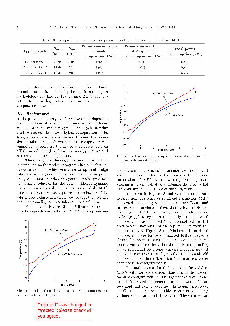
For instance, Figures 6 and 7 illustrate the bal-anced composite curves for two MRCs after optimizing
Figure 6. The balanced composite curve of con�gurationA mixed refrigerant cycle.
Figure 7. The balanced composite curve of con�gurationB mixed refrigerant cycle.
the key parameters using an enumerative method. Itshould be noticed that in these curves, the thermalintegration of MRC with low temperature processstreams is accomplished by combining the process hotand cold streams and those of the refrigerant.
As shown in Figures 3 and 4, the heat of con-densing from the compressed Mixed Refrigerant (MR)is ejected to cooling water in condenser E-504 andin the pure-propylene refrigeration cycle. To observethe impact of MRC on the precooling refrigerationcycle (propylene cycle in this study), the balancedcomposite curves of the MRC can be modi�ed, so thatthey become indicative of the rejected heat from thecompressed MR. Figures 8 and 9 indicate the modi�edcomposite curves for two optimized MRCs, called aGrand Composite Curve (GCC). Dashed lines in these�gures represent condensation of the MR in the coolingwater and liquid propylene refrigerant condensers. Itcan be derived from these �gures that the hot and coldcomposite curves in con�guration A are matched betterthan those in con�guration B.
The main reason for di�erences in the GCC ofMRCs with various con�gurations lies in the diversepossible con�guration and arrangement of these cyclesand their related equipment. In other words, it canbe stated that having optimized the design variables ofMRCs, their GCCs are suitable criteria in comparingvarious con�gurations of these cycles. These curves can

M. Ma� et al./Scientia Iranica, Transactions B: Mechanical Engineering 20 (2013) 1{14 9
Figure 8. The GCC of con�guration A mixed refrigerantcycle.
Figure 9. The GCC of con�guration B mixed refrigerantcycle.
be regarded as a qualitative criterion to measure cycledeviation from the desired condition (close matchingbetween hot and cold composite curves).
The composite curves can be redrawn by replac-ing the temperature with the Carnot factor (� =1 � [T0=T ]), resulting in the ECC (exergy compositecurves) as shown in Figures 10 and 11. The areabetween the curves in these diagrams represents theexergy loss in the utility exchangers [21]. The question,here, is whether the changes in the area enclosed inECC, given for MRCs, due to change in the cyclearrangement, equal the changes in cycle power con-sumption.
In response to the above question, consider Ta-bles 4 and 5 and compare the di�erence between thevalues of the enclosed area between MR condensationand liquid propylene refrigerant curves (light greycolored region), and also the hot and cold compositecurves (dark grey colored region) in Figures 10 and 11with the di�erence between the power consumption ofMRCs and the propylene cycle (precooling cycle) for
Figure 10. Exergy composite curves of con�guration Amixed refrigerant cycle.
Figure 11. Exergy composite curves of con�guration Bmixed refrigerant cycle.
con�gurations A and B, optimized using the enumera-tive method.
From the data analysis of Tables 4 and 5, it isevident that values of the di�erence between powerconsumption and the one between the area of enclosedregions for con�gurations A and B are close to eachother. This di�erence can be minimized computingthe exergy losses in throttling valves and compressors,along with adding them to exergy loss in heat ex-changers (the area of the enclosed region). Therefore,ECC can be used as a tool to establish proportionalitybetween the changes in the con�guration of MRC andthe change in power consumption of the cycle.
In low temperature processes with a pure re-frigerant cycle, ECC can be used as a shaft worktargeting tool to directly estimate the change in powerconsumption of the cycle (owed to modi�cations andimprovements in the cycle con�guration) without goingthrough detailed refrigeration calculations [21]. Inother words, ECC can assist the designer in �ndingthe best refrigeration system con�guration.
MRC uses a mixture as a refrigerant instead ofa pure refrigerant. Unlike a pure refrigerant cycle,graphical targeting approaches, such as ECC and GCC,

10 M. Ma� et al./Scientia Iranica, Transactions B: Mechanical Engineering 20 (2013) 1{14
Table 4. Comparison of the di�erence between the area of light grey colored regions in Figures 10 and 11 with thedi�erence between power consumption of propylene cycles.
RowNo.
MRCcon�guration
Power consumption ofPropylene cycle compressor (kW)
Area of light greycolored region (kW)
1 Con�guration A 4089 10612 Con�guration B 4118 1093
Di�erence between the valuesof rows No. 1 & 2 (kW)
29 32
Table 5. Comparison of the di�erence between the area of dark grey colored regions in Figures 10 and 11 with thedi�erence between power consumption of MRCs.
RowNo.
MRCcon�guration
Power consumption ofMRC compressor (kW)
Area of dark greycolored region (kW)
1 Con�guration A 1876 50442 Con�guration B 1528 4841
Di�erence between the valuesof rows No. 1 & 2 (kW)
203 348
cannot be used directly to optimize the MRC con�gu-ration, because the optimization requires adjustmentsto the refrigerant composition. But, MRC features asimpler machinery con�guration in comparison witha pure refrigerant multiple stage cycle. Therefore,ECC and GCC charts can be used as a graphicaltool for feeling and understanding MRC behavior.These curves tend to provide \suggestive elements" forimproving the cycle con�guration.
Let us consider the ECC and GCC charts of theMRCs shown in Figures 3 and 4. As can be seen fromFigures 8 and 9, the gap between the hot and coldcomposite curves for con�guration A is larger in thetemperature range of -60�C to -90�C in comparisonwith con�guration B. It is caused by passing MR im-mediately after the expansion valve into the subcoolerof con�guration A, which imposes a great temperaturedi�erence, along with thermal exchange, consequentlyleading to a rise in exergy loss (Figure 10). Also,con�guration B cycle has been equipped to multistreamheat exchangers (No. 1 and No. 2 heat exchangersshown in Figure 4), which results in a better matchingbetween the hot and cold composite curves (Figure 11).
3.2. Proposed method for optimizing MRCcon�guration
Due to the power and capabilities of GCC and ECCcharts in indicating room for further improvement inthe MRC process, the systematic design method pro-posed for optimal selection of refrigerant compositionand operating pressures (Figure 5) has been extendedto cover the cycle's con�guration optimization.
Figure 12 depicts the methodology. It comprisestwo main parts: Basic design phase and detailed design
Figure 12. Proposed design method to give optimalarrangement of MRC.
phase. The procedure commences from an initial guessfor MRC con�guration.
In the basic design phase, by employing theenumerative method, the best refrigerant compositionand operating pressure of the cycle are found underconditions imposed by a low temperature process.Drawing the GCC and ECC charts is the next step. By

M. Ma� et al./Scientia Iranica, Transactions B: Mechanical Engineering 20 (2013) 1{14 11
Figure 13. A mixed refrigerant cycle suggested to obtain a better match between hot and cold streams in multistreamheat exchanger (con�guration C).
considering the match between hot and cold compositecurves of the initial guess, room for further improve-ments is indicated. Then, the designer can modify thecycle con�guration based on an understanding of MRCbehavior, heuristics and judgment. The procedurestops when no further improvement is possible.
In the detailed design phase, the MRC found fromthe basic phase is fed to a direct search method toexplore further possibilities for reducing power con-sumption.
To cut down the computational time of the explo-rative stage in the basic design phase, the search space�rstly is discriminated by using coarse steps. Then,in the next iterations, by providing a feel of the cyclebehavior as well as restricting the domain of the searchspace, the discrete steps can be found.
An illustrative example of how to utilize the pro-posed method to achieve optimal MRC con�gurationhas been presented in the next section.
3.3. Case studyIn previous sections, two MRCs have been designedon the basis of the characteristics of the ole�n plantcryogenic section in place of pure ethylene refrigeration.By considering the ECC and GCC charts of thesecycles, it was concluded that using multistream heatexchangers in the cycle con�guration will lead toa better matching between hot and cold compositecurves, resulting in lower cycle power consumption.Indeed, by using suitable multistream heat exchangers,the distribution pattern of hot and cold streams will bethen out of the designer's scope of work, and the burdenwill be on the optimization algorithm of the systematicdesign method. Knowing this idea signi�cantly aids thecycle con�guration optimization. As an example, inMRC with con�guration B, which is shown in Figure 4,the designer has proposed a certain arrangement for
heat exchangers that imposes a distribution plan of hotand cold streams. Consequently, the systematic designmethod would only be able to optimize the refrigerantcomposition and operating pressures. To overcome thisproblem, the con�guration depicted in Figure 13 hasbeen suggested, which obtains a better match betweenhot and cold streams.
Table 6 compares the optimized variables foundby the enumerative method for con�gurations B andC.
The results show that by altering the cycle con�g-uration to take better advantage of the heat integrationbetween MRC and process streams in a multistreamheat exchanger, a drastic reduction in cycle powerconsumption (239 kW) has occurred.
Figures 14 and 15 illustrate the GCC and ECCcharts of the con�guration C mixed refrigerant cycle,respectively. By comparing the GCC in con�gurationsB and C (Figures 14 and 9), a considerable improve-
Figure 14. The GCC of con�guration C mixedrefrigerant cycle.

12 M. Ma� et al./Scientia Iranica, Transactions B: Mechanical Engineering 20 (2013) 1{14
Table 6. The optimized varaibles for MRCs shown in Figures 4 and 13 using enumerative method.
Con�guration Pmin
(kPa)Pmax
(kPa)Propane(mol%)
Ethane(mol%)
Methane(mol%)
Nitrogen(mol%)
Power consumption(kW)
B 200 1250 36 34 29 1 1528C 260 800 30 45 24 1 1239
Figure 15. The ECC of con�guration C mixedrefrigerant cycle.
ment between the hot and cold composite curves canbe observed in con�guration C.
Figures 14 and 15 indicate that although theproposed design method has caused the hot and coldstreams in the heat exchanger to close each other, thereis still considerable temperature di�erence betweenhot and cold streams around the pinch point in theheat exchanger network. In order to cut down thetemperature di�erence along the heat exchanger, it ispossible to distribute the thermal exchange existingbetween cold and hot streams among several cascadeheat exchangers.
Figure 16 illustrates a two-stage MRC proposed inthis paper instead of a single-stage cycle (con�gurationC) in order to decrease the power consumption. In thiscycle, the amount of refrigerant ow in each heat ex-changer is di�erent, adding one more degree of freedomin the design of the MR systems. This extra degreeof freedom creates opportunities to achieve a more
e�cient design, but it also causes more complexities inthe modeling of MR systems. The process conditionsare set the same as in the two MRCs developed in theprevious section.
It is reasonable to assume that all outlet streamsfrom the cold end multistream have equal tempera-tures [16]. This temperature, which plays a signi�cantrole in the refrigeration cycle, is called the cycleintermediate temperature. Intermediate temperaturecan alter the shape of the hot and cold compositecurves. Figure 17 shows the ECC charts for the MRCshown in Figure 16.
Intermediate temperature can alter the shape ofthe hot and cold composite curves. In this study,the change to intermediate temperature has been donemanually, following observations and heuristics. Ta-ble 7 compares the results derived from optimization
Figure 17. The ECC of two-stage MRC, intermediatetemperature: -65�C.
Figure 16. A two-stage MRC (con�guration D).

M. Ma� et al./Scientia Iranica, Transactions B: Mechanical Engineering 20 (2013) 1{14 13
Table 7. The key parametrs of various MRCs optimized using enumerative method.
Con�guration Pmin
(kPa)Pmax
(kPa)Propane(mol%)
Ethane(mol%)
Methane(mol%)
Nitrogen(mol%)
Power consumption(kW)
B 200 1250 36 34 29 1 1528C 260 800 30 45 24 1 1239D 140 600 43 41 15 1 1230
of the parameters of the two-stage refrigeration cyclewith other cycles.
It can be found from this table that despite themore complex two-stage refrigeration cycle, in compar-ison with con�guration C, there is no drastic reductionin cycle power consumption. Thus, it can be deducedthat the con�guration C cycle is the best substitute forthe refrigeration cycle of the pure ethylene refrigerantin the ole�n plant analyzed in this study.
It should be noted that lower power consumptioncan be expected if the number of stages is increased,but inevitably results in greater complexity and dif-�culty of control. Moreover, the e�ect of reducingpower consumption by increasing the number of stagesis progressively diminished.
4. Conclusion
In this paper, a systematic design method for opti-mal selection of refrigerant composition and operatingpressures of MRC with a given con�guration has beenpresented. Based on the success of the proposedsystematic method for designing MRC with a givencon�guration, the method is extended to give theoptimal arrangement of cycle components. The essenceof the extended method is the proper combination ofpinch and exergy analysis in a visual way. Thus, thecauses of ine�ciency in the mixed refrigerant cyclecon�guration can be quickly identi�ed. Based on theseinsights, the designer can con�dently evolve betterdesigns and introduce ideas for improving the cyclearrangement.
The solution that gives the lowest shaft workrequirement may incur an extra large heat transfer areaand thus capital costs. Combining the work presentedin this paper with a design method for the synthesis ofa multistream heat exchanger, to give better guidelinesfor picking the most economic solution and minimizingtotal cost, may be considered future research work.
References
1. Gaumer, L.S. and Newton, C.L. \Combined cas-cade and multicomponent refrigeration system andmethod", US patent 3763658 (1979).
2. Gong, M., Wu, J. and Luo, E. \Performance ofthe mixed-gases Joule-Thomson refrigeration cycles
for cooling �xed-temperature heat loads", Journal ofCryogenics, 44, pp. 847-857 (2004)
3. Smith, R., Chemical Process Design and Integration,John Wiley & Sons, New York (2004).
4. Flynn Thomas, M., Cryogenic Engineering, MarcelDekker, New York (2005).
5. Podbeilniak, W.J. \Art of refrigeration", US patent2041725 (1936).
6. Kleemenko, A.P. \ One ow cascade cycle", Proceedingof the 10th International Congress of Refrigeration, 1,pp. 34-39 (1959).
7. Becdeliever, C., Kaiser, V. and Paradowski, H.\Method of arrangement for processing through lowtemperature heat exchanges in particular for treatingnatural gases and cracked gases", US patent 4072485(1978).
8. Howard, L. and Rowles, H. \Mixed refrigerant cyclefor ethylene recovery", US patent 5379597 (1995).
9. Wei, VT. \Ethylene plant refrigeration system", USpatent 2002/0174679 A1 (2002).
10. Gong, M., Wu, J., Luo, E., Qi, Y. and Zhou, Y.\Study of the single-stage mixed-gases refrigerationcycle for cooling temperature-distributed heat loads",International Journal of Thermal Science, 43, pp. 31-41 (2004).
11. Alexeev, A., Thiel, A., Harberstoh, Ch. and Quack, H.\Study of behavior in the heat exchanger of a mixedgas Joule-Thomson cooler", Advances in CryogenicsEngineering, 45, pp. 307-315 (2000).
12. Cao, W., Lu, X., Lin, W. and Gu, A. \Parametercomparison of two small-scale natural gas liquefactionprocesses in skid-mounted packages", Journal of Ap-plied Thermal Engineering, 26, pp. 898-904 (2006).
13. Remeljej, C.W. and Hoadly, A.F.A. \An exergy analy-sis of small-scale lique�ed natural gas (LNG) liquefac-tion processes", Journal of Energy, 31, pp. 1669-1683(2006).
14. Venkatarathnam, G. \Cryogenic mixed refrigerant pro-cesses", Springer: International Cryogenic MonographSeries, New York (2008).
15. Ma�, M., Mousavi Naeynian, S.M. and Amidpour,M. \Exergy analysis of multistage cascade low tem-perature refrigeration systems used in ole�n plants",International Journal of Refrigeration, 32, pp. 279-294(2009).

14 M. Ma� et al./Scientia Iranica, Transactions B: Mechanical Engineering 20 (2013) 1{14
16. Lee, G.C. \Optimal design and analysis of refrigerationsystems for low-temperature processes", PhD Thesis,UMIST, UK (2001).
17. Ma�, M., Amidpour, M. and Mousavi Naeynian, S.M.\Development in mixed re�gerant cycles used in ole�nplants", Elsevier B.V.: Advances in Gas Processing,Volume 1: Proceedings of the 1st Annual Gas Process-ing Symposium, 1, pp. 154-161 (2009).
18. Danesh, A. \PVT and phase behaviour of petroleumreservoir uids", Elsevier B.V.: Development inPetroleum Science, 47, Third impression (2003).
19. Ahmed Tarek, H., Equation of State and PVT Analy-sis: Application for Improved Reservoir Modeling, GulfPublishing Company: Houston, Texas (2007).
20. Reid, R.C., Prausnitz, J.M. and Poling, B.E., TheProperties of Gases and Liquids, McGraw-Hill, FourthEdition (1987).
21. Linnho�, B. and Dhole, V.R. \Shaftwork targets forlow temperature process design", Chemical Engineer-ing Science, 4(8), pp. 2081-2091(1992).
Biographies
Mostafa Ma� received his BS degree in MechanicalEngineering from K.N. Toosi University of Technology,Iran, in 2002, his MS degree in Mechanical Engineeringfrom Tabriz University, Iran, in 2004, and his PhDdegree in Mechanical Engineering from K.N. ToosiUniversity of Technology, Iran, in 2009. He is currentlyAssistant Professor of Mechanical Engineering at ImamKhomeini International University, Iran. His researchinterests include cryogenics systems, low temperaturerefrigeration systems, LNG plants, liquefaction andseparation systems in petrochemical industries, air-conditioning systems and energy saving. He haspublished more than 25 papers in refereed journals andconferences, and is a member of the Iranian Society ofHeating, Refrigeration and Air Conditioning Engineers(IRSHRAE).
Bahram Ghorbani obtained his BS degree in Me-chanical Engineering from the University of Mazan-daran, Iran, in 2010, and his MS degree in EnergySystem Engineering from K.N. Toosi University ofTechnology, Iran, in 2012. His research interestsare currently focused on energy saving in chemical
processes, turbomachinery and propulsion systems.
Majid Amidpour received a BS degree in ChemicalEngineering from Tehran University, Iran, and MS andPhD degrees in Process Integration and Energy Con-servation from UMIST. His speci�c research interest isenergy systems, and he has published more than 300papers in this �eld in refereed journals and conferences.
He is on the managerial board of the Iran hydro-gen and fuel cell association, member of the nationalenergy committee and the national chemical engineer-ing society, IChemE (1995-1998), AICHE (1996-1998).He is member of the editorial board of the IranianChemistry & Chemical Engineering Journal, and hassupervised 10 PhD and more than 50 MS theses in �eldsrelated to energy systems. He is currently head of theChemical Engineering Department in Azad University,Iran, and director of the MS joint degree program withKingston University and Manchester University in theUK.
His professional experiences include head of en-ergy and process optimization department in IR. R&D,research deputy in Iranian Research and DevelopingCenter for chemical industry, head of IR.R&D forchemical industry, research consultant in Ministryof Industry (innovation and energy saving), researchand also education deputy in Mechanical EngineeringFaculty at K.N. Toosi University of Technology, head ofenergy system engineering, consultant Oil and EnergyMinistries company's in Iran, power plant optimizationin Iran power stations, referee of three internationaljournal.
Seyed Mojtaba Mousavi Naeynian received hisPhD degree in Mechanical Engineering from MoscowUniversity, Russia, and is currently Associate Professorof Mechanical Engineering at K.N. Toosi University ofTechnology, in Iran. He has authored four books andnumerous professional journal articles and supervised5 PhD and more than 50 MS theses in �elds related torefrigeration systems. His research interests include:Cryogenics and Refrigeration Systems, and he is anexpert on chill space design for di�erent applications.He is a member of Iranian Society of Heating, Refrig-eration and Air Conditioning Engineers (IRSHRAE).


![Dual mixed refrigerant LNG process Uncertainty ...psdc.yu.ac.kr/images/Publications/International Journal...Uncertainty factor Xn Uncertainty factor X2 Uncertainty factor X1 W } ]uµo](https://static.documents.pub/doc/80x56/5f64147d1c7e351a7b79abd3/dual-mixed-refrigerant-lng-process-uncertainty-psdcyuackrimagespublicationsinternational.jpg)


